WO2023074810A1 - ショベル - Google Patents
ショベル Download PDFInfo
- Publication number
- WO2023074810A1 WO2023074810A1 PCT/JP2022/040197 JP2022040197W WO2023074810A1 WO 2023074810 A1 WO2023074810 A1 WO 2023074810A1 JP 2022040197 W JP2022040197 W JP 2022040197W WO 2023074810 A1 WO2023074810 A1 WO 2023074810A1
- Authority
- WO
- WIPO (PCT)
- Prior art keywords
- hydraulic
- valve
- control valve
- pressure
- main pump
- Prior art date
- Legal status (The legal status is an assumption and is not a legal conclusion. Google has not performed a legal analysis and makes no representation as to the accuracy of the status listed.)
- Ceased
Links
Images


Classifications
-
- E—FIXED CONSTRUCTIONS
- E02—HYDRAULIC ENGINEERING; FOUNDATIONS; SOIL SHIFTING
- E02F—DREDGING; SOIL-SHIFTING
- E02F9/00—Component parts of dredgers or soil-shifting machines, not restricted to one of the kinds covered by groups E02F3/00 - E02F7/00
- E02F9/20—Drives; Control devices
- E02F9/22—Hydraulic or pneumatic drives
- E02F9/2221—Control of flow rate; Load sensing arrangements
-
- F—MECHANICAL ENGINEERING; LIGHTING; HEATING; WEAPONS; BLASTING
- F15—FLUID-PRESSURE ACTUATORS; HYDRAULICS OR PNEUMATICS IN GENERAL
- F15B—SYSTEMS ACTING BY MEANS OF FLUIDS IN GENERAL; FLUID-PRESSURE ACTUATORS, e.g. SERVOMOTORS; DETAILS OF FLUID-PRESSURE SYSTEMS, NOT OTHERWISE PROVIDED FOR
- F15B11/00—Servomotor systems without provision for follow-up action; Circuits therefor
- F15B11/02—Systems essentially incorporating special features for controlling the speed or actuating force of an output member
-
- E—FIXED CONSTRUCTIONS
- E02—HYDRAULIC ENGINEERING; FOUNDATIONS; SOIL SHIFTING
- E02F—DREDGING; SOIL-SHIFTING
- E02F9/00—Component parts of dredgers or soil-shifting machines, not restricted to one of the kinds covered by groups E02F3/00 - E02F7/00
- E02F9/20—Drives; Control devices
- E02F9/22—Hydraulic or pneumatic drives
- E02F9/2203—Arrangements for controlling the attitude of actuators, e.g. speed, floating function
-
- E—FIXED CONSTRUCTIONS
- E02—HYDRAULIC ENGINEERING; FOUNDATIONS; SOIL SHIFTING
- E02F—DREDGING; SOIL-SHIFTING
- E02F9/00—Component parts of dredgers or soil-shifting machines, not restricted to one of the kinds covered by groups E02F3/00 - E02F7/00
- E02F9/20—Drives; Control devices
- E02F9/22—Hydraulic or pneumatic drives
- E02F9/2221—Control of flow rate; Load sensing arrangements
- E02F9/2239—Control of flow rate; Load sensing arrangements using two or more pumps with cross-assistance
- E02F9/2242—Control of flow rate; Load sensing arrangements using two or more pumps with cross-assistance including an electronic controller
-
- E—FIXED CONSTRUCTIONS
- E02—HYDRAULIC ENGINEERING; FOUNDATIONS; SOIL SHIFTING
- E02F—DREDGING; SOIL-SHIFTING
- E02F9/00—Component parts of dredgers or soil-shifting machines, not restricted to one of the kinds covered by groups E02F3/00 - E02F7/00
- E02F9/20—Drives; Control devices
- E02F9/22—Hydraulic or pneumatic drives
- E02F9/2264—Arrangements or adaptations of elements for hydraulic drives
- E02F9/2267—Valves or distributors
-
- E—FIXED CONSTRUCTIONS
- E02—HYDRAULIC ENGINEERING; FOUNDATIONS; SOIL SHIFTING
- E02F—DREDGING; SOIL-SHIFTING
- E02F9/00—Component parts of dredgers or soil-shifting machines, not restricted to one of the kinds covered by groups E02F3/00 - E02F7/00
- E02F9/20—Drives; Control devices
- E02F9/22—Hydraulic or pneumatic drives
- E02F9/2278—Hydraulic circuits
- E02F9/2282—Systems using center bypass type changeover valves
-
- E—FIXED CONSTRUCTIONS
- E02—HYDRAULIC ENGINEERING; FOUNDATIONS; SOIL SHIFTING
- E02F—DREDGING; SOIL-SHIFTING
- E02F9/00—Component parts of dredgers or soil-shifting machines, not restricted to one of the kinds covered by groups E02F3/00 - E02F7/00
- E02F9/20—Drives; Control devices
- E02F9/22—Hydraulic or pneumatic drives
- E02F9/2278—Hydraulic circuits
- E02F9/2285—Pilot-operated systems
-
- E—FIXED CONSTRUCTIONS
- E02—HYDRAULIC ENGINEERING; FOUNDATIONS; SOIL SHIFTING
- E02F—DREDGING; SOIL-SHIFTING
- E02F9/00—Component parts of dredgers or soil-shifting machines, not restricted to one of the kinds covered by groups E02F3/00 - E02F7/00
- E02F9/20—Drives; Control devices
- E02F9/22—Hydraulic or pneumatic drives
- E02F9/2278—Hydraulic circuits
- E02F9/2292—Systems with two or more pumps
-
- E—FIXED CONSTRUCTIONS
- E02—HYDRAULIC ENGINEERING; FOUNDATIONS; SOIL SHIFTING
- E02F—DREDGING; SOIL-SHIFTING
- E02F9/00—Component parts of dredgers or soil-shifting machines, not restricted to one of the kinds covered by groups E02F3/00 - E02F7/00
- E02F9/20—Drives; Control devices
- E02F9/22—Hydraulic or pneumatic drives
- E02F9/2278—Hydraulic circuits
- E02F9/2296—Systems with a variable displacement pump
-
- F—MECHANICAL ENGINEERING; LIGHTING; HEATING; WEAPONS; BLASTING
- F15—FLUID-PRESSURE ACTUATORS; HYDRAULICS OR PNEUMATICS IN GENERAL
- F15B—SYSTEMS ACTING BY MEANS OF FLUIDS IN GENERAL; FLUID-PRESSURE ACTUATORS, e.g. SERVOMOTORS; DETAILS OF FLUID-PRESSURE SYSTEMS, NOT OTHERWISE PROVIDED FOR
- F15B11/00—Servomotor systems without provision for follow-up action; Circuits therefor
- F15B11/16—Servomotor systems without provision for follow-up action; Circuits therefor with two or more servomotors
- F15B11/17—Servomotor systems without provision for follow-up action; Circuits therefor with two or more servomotors using two or more pumps
-
- B—PERFORMING OPERATIONS; TRANSPORTING
- B60—VEHICLES IN GENERAL
- B60Y—INDEXING SCHEME RELATING TO ASPECTS CROSS-CUTTING VEHICLE TECHNOLOGY
- B60Y2200/00—Type of vehicle
- B60Y2200/40—Special vehicles
- B60Y2200/41—Construction vehicles, e.g. graders, excavators
- B60Y2200/412—Excavators
-
- E—FIXED CONSTRUCTIONS
- E02—HYDRAULIC ENGINEERING; FOUNDATIONS; SOIL SHIFTING
- E02F—DREDGING; SOIL-SHIFTING
- E02F3/00—Dredgers; Soil-shifting machines
- E02F3/04—Dredgers; Soil-shifting machines mechanically-driven
- E02F3/28—Dredgers; Soil-shifting machines mechanically-driven with digging tools mounted on a dipper- or bucket-arm, i.e. there is either one arm or a pair of arms, e.g. dippers, buckets
- E02F3/36—Component parts
- E02F3/42—Drives for dippers, buckets, dipper-arms or bucket-arms
- E02F3/43—Control of dipper or bucket position; Control of sequence of drive operations
- E02F3/435—Control of dipper or bucket position; Control of sequence of drive operations for dipper-arms, backhoes or the like
-
- F—MECHANICAL ENGINEERING; LIGHTING; HEATING; WEAPONS; BLASTING
- F15—FLUID-PRESSURE ACTUATORS; HYDRAULICS OR PNEUMATICS IN GENERAL
- F15B—SYSTEMS ACTING BY MEANS OF FLUIDS IN GENERAL; FLUID-PRESSURE ACTUATORS, e.g. SERVOMOTORS; DETAILS OF FLUID-PRESSURE SYSTEMS, NOT OTHERWISE PROVIDED FOR
- F15B2211/00—Circuits for servomotor systems
- F15B2211/30—Directional control
- F15B2211/305—Directional control characterised by the type of valves
- F15B2211/30525—Directional control valves, e.g. 4/3-directional control valve
-
- F—MECHANICAL ENGINEERING; LIGHTING; HEATING; WEAPONS; BLASTING
- F15—FLUID-PRESSURE ACTUATORS; HYDRAULICS OR PNEUMATICS IN GENERAL
- F15B—SYSTEMS ACTING BY MEANS OF FLUIDS IN GENERAL; FLUID-PRESSURE ACTUATORS, e.g. SERVOMOTORS; DETAILS OF FLUID-PRESSURE SYSTEMS, NOT OTHERWISE PROVIDED FOR
- F15B2211/00—Circuits for servomotor systems
- F15B2211/40—Flow control
- F15B2211/45—Control of bleed-off flow, e.g. control of bypass flow to the return line
Definitions
- This disclosure relates to excavators.
- An excavator includes a lower traveling body, an upper revolving body rotatably mounted on the lower traveling body, an attachment including a boom, an arm, and a bucket attached to the upper revolving body, A control valve capable of merging hydraulic oil discharged from each of a plurality of hydraulic pumps; The control valve is operated when at least two of the arm and the bucket are operating simultaneously.
- the excavator described above can reduce the pressure loss that can occur when a combined operation is performed to move at least two of the boom cylinder, arm cylinder, and bucket cylinder.
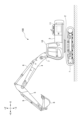
- FIG. 1 is a side view of a shovel according to an embodiment of the present invention
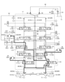
- FIG. 2 is a schematic diagram showing a configuration example of a drive system mounted on the excavator of FIG. 1
- FIG. FIG. 4 is a diagram showing the state of the drive system when the excavator is running
- FIG. 5 is a diagram showing the state of the drive system when the excavator is turning while traveling
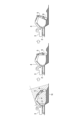
- It is a figure explaining the flow of plowing work.
- 6 is a flow chart showing a flow of an example of pressure loss suppression processing
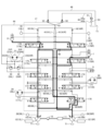
- Fig. 3 shows the state of the drive system when a plowing operation is taking place;
- FIG. 1 is a side view of a shovel 100.
- FIG. An upper revolving body 3 is rotatably mounted on a lower traveling body 1 of the excavator 100 shown in FIG. 1 through a revolving mechanism 2 .
- a boom 4 is attached to the upper swing body 3 as a working element.
- An arm 5 as a working element is attached to the tip of the boom 4
- a bucket 6 as a working element and an end attachment is attached to the tip of the arm 5 .
- the boom 4, arm 5, and bucket 6 constitute an excavation attachment, which is an example of an attachment.
- Boom 4 is driven by boom cylinder 7
- arm 5 is driven by arm cylinder 8
- bucket 6 is driven by bucket cylinder 9 .
- the upper swing body 3 is provided with a cabin 10 and is equipped with a power source such as an engine 11 .
- FIG. 2 is a diagram showing a configuration example of a drive system mounted on the excavator 100 of FIG.
- the mechanical power transmission lines are shown with double lines
- the hydraulic lines are shown with solid lines
- the pilot lines are shown with dashed lines
- the electrical control lines are shown with dashed lines.
- the excavator 100 drive system mainly includes an engine 11, a pump regulator 13, a main pump 14, a pilot pump 15, an operation device 26, a discharge pressure sensor 28, an operation sensor 29, a controller 30, and the like.
- the engine 11 is an example of a drive source for the shovel 100.
- the drive source may be an electric motor, a fuel cell, a hydrogen engine, or the like.
- the engine 11 is a diesel engine that operates to maintain a predetermined number of revolutions.
- An output shaft of the engine 11 is connected to respective input shafts of the main pump 14 and the pilot pump 15 .
- the main pump 14 is an example of a hydraulic pump, and is configured to supply hydraulic oil to the control valve unit 17.
- the main pump 14 is a swash plate type variable displacement hydraulic pump, and includes a left main pump 14L and a right main pump 14R.
- the pump regulator 13 is configured to control the discharge amount of the main pump 14 .
- the pump regulator 13 adjusts the tilt angle of the swash plate of the main pump 14 according to a command from the controller 30 to control the discharge amount of the main pump 14 .
- the pump regulator 13 may output information regarding the swash plate tilt angle to the controller 30 .
- the pump regulator 13 includes a left pump regulator 13L that controls the discharge amount of the left main pump 14L, and a right pump regulator 13R that controls the discharge amount of the right main pump 14R.
- the pilot pump 15 is configured to supply hydraulic fluid to various hydraulic devices including the operating device 26.
- the pilot pump 15 is a fixed displacement hydraulic pump.
- the pilot pump 15 may be omitted.
- the function previously performed by the pilot pump 15 may be realized by the main pump 14 .
- the main pump 14 has a function of supplying hydraulic oil to the operating device 26 and the like after reducing the pressure of the hydraulic oil by means of a throttle or the like, in addition to the function of supplying the hydraulic oil to the control valve unit 17 . good too.
- the control valve unit 17 is configured to operably accommodate a plurality of control valves.
- the control valve unit 17 includes a plurality of control valves that control the flow of hydraulic oil discharged by the main pump 14 .
- the control valve unit 17 is configured to selectively supply hydraulic fluid discharged by the main pump 14 to one or more hydraulic actuators through these control valves.
- a plurality of control valves control the flow rate of hydraulic fluid flowing from the main pump 14 to the hydraulic actuator and the flow rate of hydraulic fluid flowing from the hydraulic actuator to the hydraulic fluid tank T1.
- the hydraulic actuators include boom cylinder 7 , arm cylinder 8 , bucket cylinder 9 , travel hydraulic motor 20 , and turning hydraulic motor 21 .
- the traveling hydraulic motor 20 includes a left traveling hydraulic motor 20L and a right traveling hydraulic motor 20R.
- the revolving hydraulic motor 21 is a hydraulic motor that revolves the upper revolving body 3 .
- An oil passage 21 ⁇ /b>P connected to a port of the turning hydraulic motor 21 is connected to an oil passage 44 via a relief valve 22 and a check valve 23 .
- the oil passage 21P includes a left oil passage 21PL and a right oil passage 21PR.
- the relief valve 22 includes a left relief valve 22L and a right relief valve 22R.
- the check valve 23 includes a left check valve 23L and a right check valve 23R.
- the left relief valve 22L opens and discharges the hydraulic oil in the left oil passage 21PL to the oil passage 44 when the pressure of the hydraulic oil in the left oil passage 21PL reaches a predetermined relief pressure. Further, the right relief valve 22R opens when the pressure of the working oil in the right oil passage 21PR reaches a predetermined relief pressure, and discharges the working oil in the right oil passage 21PR to the oil passage 44.
- the left check valve 23L opens when the pressure of hydraulic oil in the left oil passage 21PL becomes lower than the pressure of hydraulic oil in the oil passage 44, and supplies hydraulic oil from the oil passage 44 to the left oil passage 21PL.
- the right check valve 23R opens when the pressure of hydraulic fluid in the right oil passage 21PR becomes lower than the pressure of hydraulic fluid in the oil passage 44, and supplies hydraulic oil from the oil passage 44 to the right oil passage 21PR.
- the operating device 26 is a device used by the operator to operate the hydraulic actuator.
- the operation device 26 is hydraulic, and supplies the hydraulic oil discharged by the pilot pump 15 to the pilot ports of the control valves corresponding to the respective hydraulic actuators via pilot lines.
- the pilot pressure which is the pressure of the hydraulic fluid supplied to each of the pilot ports, is pressure corresponding to the operation direction and amount of operation of the levers or pedals constituting the operation device 26 corresponding to each of the hydraulic actuators.
- the operating device 26 may be electric.
- the operating device 26 includes a left operating lever, a right operating lever, a left traveling lever, a right traveling lever, a left traveling operating pedal, a right traveling pedal, and the like.
- the left control lever functions as an arm control lever and a turning control lever.
- the right operating lever functions as a boom operating lever and a bucket operating lever.
- at least one of the left operating lever and the right operating lever may be referred to as an "attachment operating device”
- at least one of the left traveling lever, the right traveling lever, the left traveling pedal, and the right traveling pedal may be referred to as the " It may be referred to as a “travel operation device”.
- the left travel lever and the right travel lever are sometimes referred to as “travel levers”, and the left travel pedal and the right travel pedal are sometimes referred to as “travel pedals”. At least one of the left travel lever and left travel pedal is sometimes referred to as a “left travel operation device”, and at least one of the right travel lever and right travel pedal is referred to as a "right travel operation device”. Sometimes.
- the temperature sensor 27 is configured to detect the temperature of the hydraulic oil in the hydraulic oil tank T1 and output the detected value to the controller 30.
- the discharge pressure sensor 28 is configured to detect the discharge pressure of the main pump 14 and output the detected value to the controller 30 .
- the discharge pressure sensor 28 includes a left discharge pressure sensor 28L that detects the discharge pressure of the left main pump 14L and a right discharge pressure sensor 28R that detects the discharge pressure of the right main pump 14R.
- the operation sensor 29 is a device for detecting the content of an operator's operation using the operation device 26 .
- the operation content is, for example, an operation direction and an operation amount (operation angle).
- the operation sensor 29 is a pressure sensor that detects, in the form of pressure, the operation direction and amount of operation of the lever or pedal that constitutes the operation device 26 corresponding to each of the hydraulic actuators. Output for However, the operation content of the operation device 26 may be detected using the output of a device other than the pressure sensor, such as an operation angle sensor, acceleration sensor, angular velocity sensor, resolver, voltmeter, or ammeter.
- the controller 30 is an example of a processing circuit and functions as a control device for controlling the shovel 100.
- the controller 30 is configured by a computer including a CPU, a volatile memory device, a non-volatile memory device, and the like.
- the solenoid valve 31 is arranged in a pipeline that connects the pilot pump 15 and the pilot port of the control valve 170 in the control valve unit 17, and is configured to change the flow area of the pipeline.
- the electromagnetic valve 31 is an electromagnetic proportional control valve that operates according to a control command output by the controller 30 . Therefore, the controller 30 can supply the hydraulic oil discharged by the pilot pump 15 to the pilot port of the control valve 170 as a straight traveling valve through the solenoid valve 31 regardless of the operation of the operating device 26 by the operator.
- the controller 30 can cause the pilot pressure generated by the solenoid valve 31 to act on the pilot port of the control valve 170 .
- the center bypass oil passage 40 is a hydraulic oil line passing through control valves arranged within the control valve unit 17, and includes a left center bypass oil passage 40L and a right center bypass oil passage 40R.
- the control valve 170 is a spool valve as a straight travel valve.
- the control valve 170 essentially remains stationary when the excavator 100 is not running.
- the control valve 170 is configured to switch the flow of hydraulic oil so that the hydraulic oil is appropriately supplied from the main pump 14 to the traveling hydraulic motor 20 in order to improve the straightness of the lower traveling body 1 .
- the control valve 170 is configured to switch its valve position between a first valve position and a second valve position according to a control command from the controller 30 .
- valve position of the control valve 170 is the first valve position when only the travel operation device is operated or when only the attachment operation device is operated.
- the second valve position is when the device is operated at the same time.
- the control valve 170 remains stationary when the excavator 100 is not running, as described above. That is, the valve position of the control valve 170 is maintained at the first valve position unless the traveling operation device and the attachment operation device are operated simultaneously.
- the first valve position is a valve position that allows communication between the left main pump 14L and the left traveling hydraulic motor 20L and communication between the right main pump 14R and the right traveling hydraulic motor 20R.
- FIG. 3 shows the state of the drive system when only the traction controls are operated and the control valve 170 is switched to the first valve position. Specifically, FIG. 3 shows the state of the drive system when each of the left travel lever and the right travel lever is operated by the same amount in the forward direction. In this state, the left main pump 14L can supply hydraulic fluid to the left traveling hydraulic motor 20L, and the right main pump 14R can supply hydraulic fluid to the right traveling hydraulic motor 20R.
- FIG. 3 shows hydraulic fluid flowing from the left main pump 14L to the left traveling hydraulic motor 20L and hydraulic fluid flowing from the right main pump 14R to the right traveling hydraulic motor 20R with thick solid lines.
- the second valve position is a valve position that allows communication between the left main pump 14L and the left traveling hydraulic motor 20L and the right traveling hydraulic motor 20R, respectively.
- FIG. 4 shows the state of the drive system when the travel operating device and the attachment operating device are operated simultaneously and the control valve 170 is in the second valve position. Specifically, FIG. 4 shows a case where the left travel lever and the right travel lever are each operated in the forward direction by the same amount of operation, and the left operation lever as the turning operation lever is operated in the right turning direction. indicates the state of the drive system. In this state, the left main pump 14L can supply hydraulic fluid to each of the left travel hydraulic motor 20L and the right travel hydraulic motor 20R. For clarity, FIG. 4 shows hydraulic oil flowing from the left main pump 14L to the left traveling hydraulic motor 20L and right traveling hydraulic motor 20R, respectively, and hydraulic oil flowing from the right main pump 14R to the turning hydraulic motor 21. is represented by a thick solid line.
- control valve 170 when the control valve 170 is positioned at an intermediate valve position between the first valve position and the second valve position, the control valve 170 is configured so that the hydraulic oil discharged by the left main pump 14L and the right main pump 14R are discharged. It is configured so that it can be merged with the operating oil.
- the controller 30 outputs a control command (for example, a current command) to the solenoid valve 31 according to the operation of the operating device 26 by the operator, or regardless of the operation of the operating device 26 by the operator, to operate the pilot pump.
- a control command for example, a current command
- 15 can be supplied to a pilot port of a control valve 170 as a straight travel valve.
- the controller 30 can cause the pilot pressure generated by the solenoid valve 31 to act on the pilot port of the control valve 170 . Therefore, the controller 30 can switch the valve position of the control valve 170 between the first valve position and the second valve position at any timing.
- the control valve 171 switches the flow of hydraulic fluid in order to supply the hydraulic fluid discharged by the main pump 14 to the traveling hydraulic motor 20 and to discharge the hydraulic fluid discharged from the traveling hydraulic motor 20 to the hydraulic fluid tank. It is a spool valve. Specifically, the control valve 171 includes a control valve 171L and a control valve 171R. The control valve 171L supplies the hydraulic fluid discharged from the left main pump 14L to the left traveling hydraulic motor 20L and discharges the hydraulic fluid discharged from the left traveling hydraulic motor 20L to the hydraulic fluid tank. switch the flow.
- the control valve 171R supplies the hydraulic fluid discharged from the left main pump 14L or the right main pump 14R to the right traveling hydraulic motor 20R, and discharges the hydraulic fluid discharged from the right traveling hydraulic motor 20R to the hydraulic fluid tank. to switch the hydraulic oil flow.
- the control valve 172 supplies the hydraulic fluid discharged by the left main pump 14L to the optional hydraulic actuator, and the hydraulic fluid discharged by the optional hydraulic actuator is discharged to the hydraulic fluid tank.
- An optional hydraulic actuator is, for example, a grapple open/close cylinder.
- the control valve 173 supplies hydraulic fluid discharged by the left main pump 14L to the turning hydraulic motor 21, and controls the flow of hydraulic fluid in order to discharge the hydraulic fluid discharged by the turning hydraulic motor 21 to the hydraulic fluid tank. It is a switching spool valve.
- the control valve 174 is a spool valve for supplying the hydraulic oil discharged by the right main pump 14R to the bucket cylinder 9 and discharging the hydraulic oil in the bucket cylinder 9 to the hydraulic oil tank.
- the control valve 175 is a spool valve that switches the flow of hydraulic oil to supply the hydraulic oil discharged by the main pump 14 to the boom cylinder 7 and to discharge the hydraulic oil in the boom cylinder 7 to the hydraulic oil tank.
- the control valve 175 includes a control valve 175L and a control valve 175R.
- the control valve 175L operates only when the boom 4 is raised, and does not operate when the boom 4 is lowered.
- the control valve 176 is a spool valve that switches the flow of hydraulic fluid to supply the hydraulic fluid discharged by the main pump 14 to the arm cylinder 8 and to discharge the hydraulic fluid in the arm cylinder 8 to the hydraulic fluid tank.
- the control valve 176 includes a control valve 176L and a control valve 176R.
- control valves 170 to 176 are pilot spool valves in this embodiment, they may be electromagnetic spool valves when the operating device 26 is electric.
- the lever operation amount is input to the controller 30 as an electric signal.
- a solenoid valve is arranged between the pilot pump 15 and the pilot port of each control valve.
- the solenoid valve is configured to operate in response to an electrical signal from controller 30 .
- the controller 30 controls the solenoid valve with an electric signal corresponding to the lever operation amount to increase or decrease the pilot pressure, thereby moving each control valve.
- Each control valve may be composed of an electromagnetic spool valve as described above. In this case, the electromagnetic spool valve operates according to an electric signal from the controller 30 corresponding to the lever operation amount of the electric operation lever.
- the return oil passage 41 is a hydraulic oil line arranged within the control valve unit 17 and includes a left return oil passage 41L and a right return oil passage 41R. Hydraulic oil that has flowed out of the hydraulic actuator and passed through the control valves 171 to 176 flows through the return oil passage 41 toward the hydraulic oil tank T1.
- a parallel oil passage 42 is a hydraulic oil line parallel to the center bypass oil passage 40 .
- the parallel oil passage 42 includes a left parallel oil passage 42L parallel to the left center bypass oil passage 40L and a right parallel oil passage 42R parallel to the right center bypass oil passage 40R.
- the left parallel oil passage 42L can supply hydraulic oil to more downstream control valves when the flow of hydraulic oil through the left center bypass oil passage 40L is restricted or blocked by the control valves 171L, 172, 173, or 175L.
- the right parallel oil passage 42R can supply hydraulic oil to more downstream control valves when the flow of hydraulic oil through the right center bypass oil passage 40R is restricted or blocked by the control valves 171R, 174, or 175R.
- the throttle 60 is arranged in the right parallel oil passage 42R upstream of the control valve 176R and downstream of a branch point where the oil passage connecting the right parallel oil passage 42R and the control valve 175R branches off from the right parallel oil passage 42R. It is a fixed diaphragm provided.
- the throttle 60 includes, for example, an arm cylinder 8 with a low load pressure and a hydraulic actuator with a high load pressure (at least one of the boom cylinder 7, the bucket cylinder 9, and the right travel hydraulic motor 20R). It has a function of preventing most of the hydraulic oil discharged from the right main pump 14R from flowing into the arm cylinder 8 with a low load pressure when they are operated simultaneously.
- the throttle 60 can increase the pressure of the hydraulic fluid on the downstream side when the hydraulic fluid flows into the arm cylinder 8 through the control valve 176R. Therefore, even when the arm cylinder 8 with low load pressure and the boom cylinder 7 with high load pressure are operated at the same time, the drive system including the throttle 60 is operated not only with the arm cylinder 8 with low load pressure, but also with the boom cylinder 7 with high load pressure. Even the boom cylinder 7 with high load pressure can be reliably operated. The same applies to the case where the arm cylinder 8 with low load pressure and the bucket cylinder 9 with high load pressure or the right travel hydraulic motor 20R are operated at the same time.
- throttles 18 are arranged between each of the most downstream control valves 175 and the hydraulic oil tank T1.
- a throttle 18 restricts the flow of hydraulic oil discharged by the main pump 14 .
- the throttle 18 generates a control pressure (negative control pressure) for controlling the pump regulator 13 .
- the diaphragm 18 is a fixed diaphragm with a fixed aperture area, and includes a left diaphragm 18L and a right diaphragm 18R.
- the aperture 18 tends to increase stability against sudden changes in the control pressure as the opening area increases.
- the throttle 18 tends to increase the responsiveness of the control pressure as the opening area becomes smaller.
- the flow of hydraulic oil discharged from the left main pump 14L is restricted by the left throttle 18L.
- the left throttle 18L generates a control pressure for controlling the left pump regulator 13L.
- the flow of hydraulic fluid discharged from the right main pump 14R is restricted by the right throttle 18R.
- the right throttle 18R generates a control pressure for controlling the right pump regulator 13R.
- the control pressure sensor 19 is a sensor that detects control pressure (negative control pressure) generated upstream of the throttle 18, and includes a left control pressure sensor 19L and a right control pressure sensor 19R. In this embodiment, the control pressure sensor 19 is configured to output the detected value to the controller 30 . Controller 30 outputs a command corresponding to the control pressure to pump regulator 13 .
- the pump regulator 13 controls the discharge amount of the main pump 14 by adjusting the tilt angle of the swash plate of the main pump 14 according to the command. Specifically, the pump regulator 13 reduces the discharge amount of the main pump 14 as the control pressure increases, and increases the discharge amount of the main pump 14 as the control pressure decreases.
- the drive system of FIG. 2 can suppress wasteful energy consumption in the main pump 14 when none of the hydraulic actuators are operated. Wasteful energy consumption includes pumping loss caused by the hydraulic oil discharged by the main pump 14 in the center bypass oil passage 40 . To reliably supply necessary and sufficient working oil from a main pump 14 to a hydraulic actuator to be operated when the hydraulic actuator is operated.
- the center bypass oil passage 40 and the return oil passage 41 are connected to the junction of the oil passages 43 downstream of the throttle 18 .
- the oil passage 43 branches into two at the downstream of the confluence and is connected to the oil passages 45 and 46 outside the control valve unit 17 . That is, the hydraulic fluid flowing through the center bypass oil passage 40 and the return oil passage 41 respectively joins in the oil passage 43 and then passes through the oil passage 45 or the oil passage 46 to reach the hydraulic oil tank T1. Further, the oil passage 43 is connected to the turning hydraulic motor 21 via an oil passage 44 which is a hydraulic oil line for compensating for the shortage of hydraulic oil on the suction side of the turning hydraulic motor 21 .
- the oil passage 45 is a hydraulic oil line that connects the oil passage 43 and the hydraulic oil tank T1.
- a check valve 50 , an oil cooler 51 and a filter 53 are arranged in the oil passage 45 .
- the check valve 50 is a valve that opens when the pressure difference between the primary side and the secondary side exceeds a predetermined valve opening pressure difference.
- the check valve 50 is a spring-type check valve that opens when the pressure on the upstream side is higher than the pressure on the downstream side and the pressure difference exceeds the valve opening pressure difference. Hydraulic oil is caused to flow out toward the oil cooler 51 .
- the check valve 50 can maintain the pressure of the hydraulic oil in the oil passages 43 and 44 at a level higher than the valve opening pressure, and can reliably compensate for the shortage of hydraulic oil on the suction side of the turning hydraulic motor 21. make it In this case, the valve opening pressure is the lower limit of the back pressure for the throttle 18 .
- the back pressure on the throttle 18 increases as the flow rate of hydraulic fluid passing through the check valve 50 increases.
- the check valve 50 may be integrated with the control valve unit 17 or may be omitted. When the check valve 50 is omitted, the pressure loss in each of the oil passage 45 , check valve 50 , oil cooler 51 and filter 53 becomes back pressure to the throttle 18 . The back pressure on the throttle 18 increases as the flow rate of hydraulic fluid passing through the oil passage 45 increases.
- the oil cooler 51 is a device for cooling hydraulic oil circulating in the drive system.
- the oil cooler 51 is included in a heat exchanger unit cooled by a cooling fan driven by the engine 11 .
- the heat exchanger unit includes a radiator, an intercooler, an oil cooler 51, and the like.
- the oil passage 45 includes an oil passage portion 45a connecting the check valve 50 and the oil cooler 51, and an oil passage portion 45b connecting the oil cooler 51 and the hydraulic oil tank T1.
- a filter 53 is arranged in the oil passage portion 45b.
- the oil passage 46 is a bypass oil passage that bypasses the oil cooler 51 .
- the oil passage 46 has one end connected to the oil passage 43 and the other end connected to the hydraulic oil tank T1. One end may be connected to the oil passage 45 between the check valve 50 and the oil cooler 51 .
- a check valve 52 is arranged in the oil passage 46 .
- the check valve 52 is a valve that opens when the pressure difference between the primary side and the secondary side exceeds a predetermined valve opening pressure difference.
- the check valve 52 is a spring-type check valve that opens when the pressure on the upstream side is higher than the pressure on the downstream side and the pressure difference exceeds the valve opening pressure difference. Hydraulic oil is caused to flow out toward the hydraulic oil tank T1.
- the opening pressure difference of the check valve 52 is greater than the opening pressure difference of the check valve 50 . Therefore, the hydraulic oil in the control valve unit 17 first flows through the check valve 50, and then flows through the check valve 52 when the pressure exceeds the valve opening pressure due to resistance when flowing through the oil cooler 51.
- the check valve 52 may be integrated with the control valve unit 17 .
- the pressure loss suppression process is a process for suppressing pressure loss that occurs in the hydraulic oil line when a predetermined combined action is being performed.
- FIG. 5 is a diagram illustrating the flow of a plowing work as an example of work realized by a combined motion including an arm closing motion and a boom raising motion, which are an example of a predetermined combined motion.
- Plowing work is a work for scraping off excess undulations of the ground surface flatly.
- FIG. 6 is a flowchart showing the flow of pressure loss suppression processing. The controller 30 repeatedly executes this pressure loss suppression process at a predetermined control cycle.
- the operator places the tip of the bucket 6 on the ground to be worked within the working area N of the excavation attachment (the boom 4, the arm 5, and the bucket 6) as the working device.
- the tip of the bucket 6 is positioned so as to be at a desired height position.
- the work area N means, for example, an area reachable by the tip of the bucket 6 .
- the bucket 6 is in an open state (for example, the state of the bucket 6 when the bucket angle is 90 degrees or more).
- the bucket angle is, for example, the opening angle of the bucket 6 from the most closed state (rotational angle of the bucket 6 around the bucket pin).
- the operator starts the plowing work by closing the arm 5 while gradually raising the boom 4. Specifically, the operator executes the arm closing operation by full lever operation of the arm operation lever, and executes the boom raising operation by fine operation or half lever operation of the boom operation lever.
- Fine operation is defined as, for example, the amount of lever operation when the operation lever is in the neutral position is 0%, and the amount of lever operation when the operation lever is tilted to the maximum is 100%, and the lever is less than 20%. It means operation with manipulated variable.
- Full lever operation means, for example, operation with a lever operation amount of 80% or more.
- Half-lever operation means operation with a lever operation amount of 20% or more and less than 80%, for example.
- the fine operation and the half lever operation may be collectively referred to as "non-full lever operation".
- the operator continues the plowing work by closing the arm 5 while gradually raising the boom 4 from the state shown in the center diagram of FIG. Specifically, the operator continues the arm closing operation by full lever operation of the arm operation lever, and continues the boom raising operation by fine operation or half lever operation of the boom operation lever. As a result, excess undulations on the ground surface are scraped flat by the tip of the bucket 6 .
- the hydraulic oil discharged from the left main pump 14L passes through the left center bypass oil passage 40L and the left parallel oil passage 42L respectively, reaches the control valve 176L, and then reaches the control valve 176L. It reaches the bottom side oil chamber of the arm cylinder 8 through the control valve 176L. Also, part of the hydraulic oil discharged by the right main pump 14R reaches the control valve 176R through the right parallel oil passage 42R and then reaches the bottom side oil chamber of the arm cylinder 8 through the control valve 176R.
- Another portion of the hydraulic oil discharged by the right main pump 14R reaches the control valve 175R through the right parallel oil passage 42R and then reaches the bottom side oil chamber of the boom cylinder 7 through the control valve 175R.
- the discharge amounts of the left main pump 14L and the right main pump 14R are increased to the maximum discharge amount by negative control because the arm control lever is fully operated.
- the cross section of the right parallel oil passage 42R leading to the control valve 176R is narrowed by the throttle 60, and the pressure of the hydraulic oil on the upstream side of the throttle 60 becomes higher than the pressure of the hydraulic oil on the downstream side of the throttle 60.
- a combined action (first combined action) that includes an arm closing action achieved by fine operation or half-lever operation of the arm control lever and a boom raising action achieved by fine operation or half-lever operation of the boom control lever.
- most of the hydraulic fluid discharged from the right main pump 14R flows into the arm cylinder 8, preventing the hydraulic fluid discharged from the right main pump 14R from flowing into the boom cylinder 7. is. That is, this is to prevent the boom raising operation from slowing down even though the load is small during the combined operation.
- the hydraulic oil discharged by the right main pump 14R causes pressure loss when passing through the throttle 60.
- the pressure loss increases as the flow rate of hydraulic oil discharged from the right main pump 14R increases.
- it is achieved by a compound operation (second compound operation) including an arm closing operation achieved by full lever operation of the arm operating lever and a boom raising operation achieved by fine operation or half lever operation of the boom operating lever.
- the pressure loss generated at the throttle 60 becomes large.
- the lever operation amount of the boom operating lever in the second compound action is smaller than the lever operation amount of the boom operating lever in the first compound action.
- the opening area of the PC port (pump-cylinder port) of the control valve 175 is also smaller, so the pressure loss in the oil passage on the right main pump 14R side also increases.
- the excavator 100 reduces the pressure loss generated at the throttle 60 by executing pressure loss suppression processing when a predetermined combined motion such as a combined motion during plowing work is performed. .
- the controller 30 mounted on the excavator 100 outputs a control command to the solenoid valve 31 and exceptionally operates the control valve 170, which basically does not operate when the excavator 100 is not traveling. Reduce the pressure loss that occurs.
- the controller 30 determines whether or not a predetermined combined action is being performed (step ST1). In the illustrated example, the controller 30 determines whether or not a predetermined combined action is being performed based on the output of the operation sensor 29 .
- Predetermined combined motions include combined motions for achieving a plowing operation.
- a compound operation for realizing plowing work is, for example, a compound operation including an arm closing operation achieved by full lever operation of the arm operation lever and a boom raising operation achieved by fine operation or half lever operation of the boom operation lever. It is action.
- the controller 30 may determine whether or not a predetermined combined action is being performed based on outputs from sensors other than the operation sensor 29 .
- the controller 30 is based on the output of a boom angle sensor, an arm angle sensor, a bucket angle sensor, or the like, or based on the output of an image sensor such as a space recognition device (camera or LIDAR) mounted on the upper swing structure 3. , it may be determined whether or not a predetermined combined action is being performed.
- a boom angle sensor an arm angle sensor, a bucket angle sensor, or the like
- an image sensor such as a space recognition device (camera or LIDAR) mounted on the upper swing structure 3.
- step ST1 the controller 30 terminates the current pressure loss suppression process. This is because it is considered that the pressure loss that should be reduced does not occur in the hydraulic oil line.
- the controller 30 compares the discharge pressure P1 of the left main pump 14L and the discharge pressure P2 of the right main pump 14R (step ST2). In the illustrated example, the controller 30 determines whether or not the discharge pressure P2 of the right main pump 14R detected by the right discharge pressure sensor 28R is greater than the discharge pressure P1 of the left main pump 14L detected by the left discharge pressure sensor 28L. judge.
- step ST2 when it is determined that the discharge pressure P2 is not greater than the discharge pressure P1 (NO in step ST2), that is, when it is determined that the discharge pressure P2 is equal to or less than the discharge pressure P1, the controller 30 performs the current pressure loss suppression process. terminate. This is because it is considered that the pressure loss that should be reduced does not occur in the hydraulic oil line.
- the controller 30 when it is determined that the discharge pressure P2 is higher than the discharge pressure P1 (YES in step ST2), the controller 30 operates the control valve 170 as a straight traveling valve (step ST3).
- the controller 30 outputs a control command to the solenoid valve 31 to position the control valve 170 at an intermediate valve position between the first valve position and the second valve position.
- the discharge pressure P1 after operating the control valve 170 becomes higher than the discharge pressure P1 before operating the control valve 170, and the discharge pressure P2 after operating the control valve 170 becomes smaller than the discharge pressure P2 before operating the .
- the fact that the discharge pressure P1 and the discharge pressure P2 are the same value may include that the differential pressure between the discharge pressure P1 and the discharge pressure P2 is less than a preset predetermined value.
- FIG. 7 shows, as an example, the state of the drive system when plowing work is being performed. Specifically, FIG. 7 shows a case where the valve position of the control valve 170 is positioned at the intermediate valve position when a combined operation including a boom raising operation by half-lever operation and an arm closing operation by full-lever operation is performed. Indicates the state of the drive system. For clarity, FIG. 7 shows hydraulic oil flowing from the left main pump 14L to the bottom side oil chamber of the arm cylinder 8, and from the right main pump 14R to the bottom side oil chamber of the arm cylinder 8 and the bottom side oil of the boom cylinder 7. Hydraulic oil flowing through each of the chambers is represented by a thick solid line.
- the controller 30 performs pressure loss suppression processing, that is, by positioning the control valve 170 at the intermediate valve position when a predetermined combined action is being performed, thereby causing pressure loss generated in the hydraulic oil line to occur. It is possible to suppress the pressure loss caused by
- the excavator 100 does not destabilize the movement of the excavation attachment by providing a configuration capable of implementing pressure loss suppression processing. This is because the pressure loss suppression process is implemented in a configuration including the throttle 60 . That is, even in a configuration that can implement the pressure loss suppression process, the throttle 60 prevents the hydraulic fluid that should flow into the hydraulic actuator (boom cylinder 7) with high load pressure from flowing into the hydraulic actuator (arm cylinder 8) with low load pressure. This is because it is possible to suppress or prevent storage.
- the controller 30 determines that the discharge pressure P2 is greater than the discharge pressure P1 when the differential pressure between the discharge pressure P2, which is greater than the discharge pressure P1, and the discharge pressure P1 is equal to or greater than a predetermined value. may be configured to That is, the controller 30 is configured to determine that the discharge pressure P2 is not greater than the discharge pressure P1 if the differential pressure is less than a predetermined value even if the discharge pressure P2 is greater than the discharge pressure P1.
- the controller 30 may be configured to keep the control valve 170 in an operating state until a predetermined release condition is satisfied after the control valve 170 as the straight traveling valve is operated. good. That is, even if the discharge pressure P1 and the discharge pressure P2 become the same after the valve position of the control valve 170 is positioned at the intermediate valve position, the controller 30 keeps the control valve 170 closed until the predetermined release condition is satisfied.
- the valve position of 170 may remain positioned in the middle valve position. This is for maintaining a state in which the pressure loss is reduced.
- the predetermined cancellation condition is to determine that the predetermined combined action determined to have been performed in step ST1 is no longer being performed.
- the controller 30 determines that the combined motion including the boom raising motion and the arm closing motion determined to be performed in step ST1 is no longer being performed.
- the valve position of control valve 170 is typically switched to the first valve position.
- the controller 30 switches the valve position of the control valve 170 to the first valve position when the combined operation including the boom raising operation and the arm closing operation shifts to a single operation including only the boom raising operation.
- the controller 30 performs control as a straight travel valve when a predetermined combined action, which is a combined action including an arm closing action by full lever operation and a boom raising action by non-full lever operation, is being performed. It is configured to actuate valve 170 .
- the controller 30 can perform a compound operation including an arm closing operation by full lever operation and a boom lowering operation by non-full lever operation, a compound operation including an arm closing operation by full lever operation and a bucket closing operation by non-full lever operation, and an arm operation by full lever operation.
- control valve 170 as a straight traveling valve may be operated when another predetermined combined action such as a combined action including an opening action is performed.
- the combined operation including the arm closing operation by full lever operation and the boom raising operation by non-full lever operation performed to realize plowing work is the full lever operation performed to realize other work such as floor excavation work. It may be a combined operation including arm closing operation by non-full lever operation and boom raising operation by non-full lever operation, and arm closing operation by full lever operation and non-full lever It may be a combined action including a boom raising action by an operation.
- the excavator 100 includes, as shown in FIGS.
- a excavation attachment which is an example of an attachment, including a boom 4, an arm 5, and a bucket 6, which is attached to the revolving structure 3, and hydraulic oil discharged from each of the plurality of hydraulic pumps can be combined as a travel straight valve.
- a control valve 170 and a controller 30 as a control device capable of controlling the movement of the control valve 170 are provided.
- the controller 30 is configured to operate the control valve 170 to perform pressure loss suppression processing when at least two of the boom 4, the arm 5, and the bucket 6 are operating simultaneously during non-traveling. ing.
- FIG. A excavation attachment, which is an example of an attachment, including a boom 4, an arm 5, and a bucket 6, which is attached to the revolving structure 3, and hydraulic oil discharged from each of the plurality of hydraulic pumps can be combined as a travel straight valve.
- a control valve 170 and a controller 30 as a control device capable of controlling the movement of the control valve 170 are provided.
- the controller 30 is
- the control valve 170 as the straight travel valve is arranged between the right main pump 14R and the control valve 171R on the right center bypass oil passage 40R, and is arranged on the left parallel oil passage 42L. It is arranged between the main pump 14L and the branch point to the control valve 172 .
- the control valve 170 as a straight travel valve is basically configured such that the valve position is switched when the travel operation device is operated. It is configured so that the valve position can be switched even when it is not on.
- the control valve 170 as a straight travel valve enables the hydraulic oil discharged by the left main pump 14L to be supplied to the left parallel oil passage 42L, and allows the hydraulic oil discharged by the right main pump 14R to be supplied to the right center pump.
- a first valve position that enables supply to the bypass oil passage 40R a first valve position that allows the hydraulic oil discharged by the left main pump 14L to be supplied to the right center bypass oil passage 40R, and a hydraulic oil that is discharged by the right main pump 14R. It is configured to be able to switch between a second valve position that enables supply to the left parallel oil passage 42L.
- the control valve 170 as a straight traveling valve combines the hydraulic fluids discharged from the left main pump 14L and the right main pump at an intermediate valve position between the first valve position and the second valve position. , so that it can be supplied to each of the left parallel oil passage 42L and the right center bypass oil passage 40R.
- the arm 5, and the bucket 6 are operating simultaneously during non-traveling operation, for example, at least two of the boom 4, the arm 5, and the bucket 6 are operated simultaneously during the non-traveling operation. when it is being manipulated.
- the controller 30 may determine whether or not at least two of the boom 4, arm 5, and bucket 6 are operating at the same time based on the output of the operation sensor 29 while the vehicle is not traveling. Alternatively, the controller 30 determines whether or not at least two of the boom 4, the arm 5, and the bucket 6 are operating simultaneously based on the outputs of the boom angle sensor, the arm angle sensor, the bucket angle sensor, and the like. good too. Alternatively, the controller 30 may determine whether the excavator 100 is running based on the output of a positioning device such as GNSS.
- the controller 30 controls at least two of the boom 4, the arm 5, and the bucket 6 to move during non-traveling. It may be determined whether or not they are operating at the same time.
- an image sensor such as a space recognition device (camera or LIDAR) mounted on the upper rotating body 3
- the controller 30 controls at least two of the boom 4, the arm 5, and the bucket 6 to move during non-traveling. It may be determined whether or not they are operating at the same time.
- the above configuration has the effect of reducing the pressure loss that can occur when a combined operation for moving at least two of the boom cylinder 7, the arm cylinder 8, and the bucket cylinder 9 is performed. Bring. Therefore, the above-described configuration brings about the effect of being able to improve the fuel consumption or the operating speed of the excavation attachment.
- the above-described configuration is configured to execute pressure loss suppression processing using the existing straight travel valve (control valve 170), the fixed throttle (throttle 60) is changed to a variable throttle, or This provides the effect of reducing the pressure loss in the hydraulic oil line without adopting a relatively high-cost method such as providing an electromagnetic proportional valve in the pilot line of the control valve 176 .
- the above-described configuration is configured to execute the pressure loss suppression process using the existing straight travel valve (control valve 170), it is possible to eliminate the need to adopt a structure or configuration that requires a separate installation space. , the effect that the pressure loss in the hydraulic oil line can be reduced.
- the above-described configuration has the effect of omitting the electromagnetic proportional valve in the excavator provided with the electromagnetic proportional valve in the pilot line of the control valve 176, thereby reducing the manufacturing cost.
- the controller 30 may be configured to operate the control valve 170 as a straight travel valve when a combined motion including at least one of the arm closing motion, the boom raising motion, and the bucket closing motion is performed. .
- the controller 30 is configured to operate the control valve 170 as a straight traveling valve only when the operation amount of the arm closing operation is larger than the operation amount of the boom raising operation and the operation amount of the bucket closing operation. good too. That is, the controller 30 operates the control valve 170 when the operation amount of the arm closing operation is equal to or less than the operation amount of the boom raising operation even when a combined operation including the arm closing operation and the boom raising operation is being performed. It may be configured not to allow This is because the pressure loss generated in the hydraulic oil line is considered to be small.
- the excavator 100 has a left main pump 14L as a first hydraulic pump capable of supplying hydraulic oil to the left traveling hydraulic motor 20L and the right traveling hydraulic motor 20R, and the right traveling hydraulic motor 20R. and a right main pump 14R as a second hydraulic pump capable of supplying hydraulic oil.
- the controller 30 controls the discharge pressure of the right main pump 14R when at least two of the boom 4, the arm 5, and the bucket 6 are operating simultaneously during non-running.
- the control valve 170 as a straight traveling valve is operated to join the hydraulic oil discharged from the left main pump 14L and the hydraulic oil discharged from the right main pump 14R. It may be configured to allow
- control valve 170 as a straight travel valve communicates the left main pump 14L with the left travel hydraulic motor 20L and communicates the right main pump 14R with the right travel hydraulic motor 20R.
- the hydraulic oil discharged by the left main pump 14L and the right main pump 14R are It may be configured to merge with the hydraulic oil to be discharged.
- This configuration has the effect of reducing the pressure loss that can occur when a combined operation is being performed to move at least two of the boom cylinder 7, arm cylinder 8, and bucket cylinder 9. .
- the pressure difference between the discharge pressure P2 of the right main pump 14R and the discharge pressure P1 of the left main pump 14L the pressure of hydraulic fluid upstream of the throttle 60 and the pressure of hydraulic fluid downstream of the throttle 60 are reduced. This is because the differential pressure between and can be reduced. Therefore, this configuration has the effect of improving fuel consumption or increasing the operating speed of the drilling attachment.
- plowing work was shown, but the work to which the present invention can be applied is not limited to plowing work.
- control valve 170 is configured as a 4-port 2-chamber spool valve. Then, the controller 30 utilizes an intermediate valve position between the first valve position and the second valve position of the control valve 170 to mix the hydraulic oil discharged by the left main pump 14L and the hydraulic oil discharged by the right main pump 14R. are configured to merge.
- control valve 170 may be configured as a 4-port 3-chamber spool valve with the intermediate valve position as an independent third valve position. That is, the control valve 170 may be configured as a 4-port, 3-chamber spool valve having an independent third valve position provided with a junction connecting the left parallel oil passage 42L and the right center bypass oil passage 40R. .
- control valve 170 may be configured so that the opening area of the confluence passage connecting the left parallel oil passage 42L and the right center bypass oil passage 40R can be changed according to the stroke amount.
Landscapes
- Engineering & Computer Science (AREA)
- General Engineering & Computer Science (AREA)
- Mining & Mineral Resources (AREA)
- Civil Engineering (AREA)
- Structural Engineering (AREA)
- Physics & Mathematics (AREA)
- Fluid Mechanics (AREA)
- Mechanical Engineering (AREA)
- Operation Control Of Excavators (AREA)
- Fluid-Pressure Circuits (AREA)
Priority Applications (5)
| Application Number | Priority Date | Filing Date | Title |
|---|---|---|---|
| EP22887135.6A EP4424929A4 (en) | 2021-10-29 | 2022-10-27 | EXCAVATOR |
| KR1020247006056A KR20240087638A (ko) | 2021-10-29 | 2022-10-27 | 쇼벨 |
| JP2023556643A JPWO2023074810A1 (https=) | 2021-10-29 | 2022-10-27 | |
| CN202280058701.3A CN117897538A (zh) | 2021-10-29 | 2022-10-27 | 挖土机 |
| US18/642,158 US12467232B2 (en) | 2021-10-29 | 2024-04-22 | Excavator |
Applications Claiming Priority (2)
| Application Number | Priority Date | Filing Date | Title |
|---|---|---|---|
| JP2021177017 | 2021-10-29 | ||
| JP2021-177017 | 2021-10-29 |
Related Child Applications (1)
| Application Number | Title | Priority Date | Filing Date |
|---|---|---|---|
| US18/642,158 Continuation US12467232B2 (en) | 2021-10-29 | 2024-04-22 | Excavator |
Publications (1)
| Publication Number | Publication Date |
|---|---|
| WO2023074810A1 true WO2023074810A1 (ja) | 2023-05-04 |
Family
ID=86160006
Family Applications (1)
| Application Number | Title | Priority Date | Filing Date |
|---|---|---|---|
| PCT/JP2022/040197 Ceased WO2023074810A1 (ja) | 2021-10-29 | 2022-10-27 | ショベル |
Country Status (6)
| Country | Link |
|---|---|
| US (1) | US12467232B2 (https=) |
| EP (1) | EP4424929A4 (https=) |
| JP (1) | JPWO2023074810A1 (https=) |
| KR (1) | KR20240087638A (https=) |
| CN (1) | CN117897538A (https=) |
| WO (1) | WO2023074810A1 (https=) |
Citations (5)
| Publication number | Priority date | Publication date | Assignee | Title |
|---|---|---|---|---|
| JP2003004005A (ja) * | 2001-06-22 | 2003-01-08 | Kobelco Contstruction Machinery Ltd | 建設機械の油圧制御回路 |
| JP2004346485A (ja) * | 2003-04-17 | 2004-12-09 | Hitachi Constr Mach Co Ltd | 油圧駆動装置 |
| JP2010174980A (ja) * | 2009-01-29 | 2010-08-12 | Komatsu Ltd | 作業車両、作業車両の制御方法、および、作業車両における油圧ポンプの斜板センサの較正方法 |
| WO2016056442A1 (ja) | 2014-10-06 | 2016-04-14 | 住友重機械工業株式会社 | ショベル |
| JP2021177017A (ja) | 2020-04-30 | 2021-11-11 | 株式会社リヒトラブ | 顔保護具 |
Family Cites Families (4)
| Publication number | Priority date | Publication date | Assignee | Title |
|---|---|---|---|---|
| US7178333B2 (en) * | 2004-03-18 | 2007-02-20 | Kobelco Construction Machinery Co., Ltd. | Hydraulic control system for hydraulic excavator |
| JP5107195B2 (ja) * | 2008-09-18 | 2012-12-26 | 住友建機株式会社 | 建設機械 |
| JP2013249849A (ja) * | 2012-05-30 | 2013-12-12 | Kobe Steel Ltd | 作業機械の油圧制御装置 |
| JP6893894B2 (ja) * | 2018-03-27 | 2021-06-23 | ヤンマーパワーテクノロジー株式会社 | 作業車両の油圧回路 |
-
2022
- 2022-10-27 CN CN202280058701.3A patent/CN117897538A/zh active Pending
- 2022-10-27 WO PCT/JP2022/040197 patent/WO2023074810A1/ja not_active Ceased
- 2022-10-27 KR KR1020247006056A patent/KR20240087638A/ko active Pending
- 2022-10-27 EP EP22887135.6A patent/EP4424929A4/en active Pending
- 2022-10-27 JP JP2023556643A patent/JPWO2023074810A1/ja active Pending
-
2024
- 2024-04-22 US US18/642,158 patent/US12467232B2/en active Active
Patent Citations (5)
| Publication number | Priority date | Publication date | Assignee | Title |
|---|---|---|---|---|
| JP2003004005A (ja) * | 2001-06-22 | 2003-01-08 | Kobelco Contstruction Machinery Ltd | 建設機械の油圧制御回路 |
| JP2004346485A (ja) * | 2003-04-17 | 2004-12-09 | Hitachi Constr Mach Co Ltd | 油圧駆動装置 |
| JP2010174980A (ja) * | 2009-01-29 | 2010-08-12 | Komatsu Ltd | 作業車両、作業車両の制御方法、および、作業車両における油圧ポンプの斜板センサの較正方法 |
| WO2016056442A1 (ja) | 2014-10-06 | 2016-04-14 | 住友重機械工業株式会社 | ショベル |
| JP2021177017A (ja) | 2020-04-30 | 2021-11-11 | 株式会社リヒトラブ | 顔保護具 |
Non-Patent Citations (1)
| Title |
|---|
| See also references of EP4424929A4 |
Also Published As
| Publication number | Publication date |
|---|---|
| EP4424929A1 (en) | 2024-09-04 |
| CN117897538A (zh) | 2024-04-16 |
| JPWO2023074810A1 (https=) | 2023-05-04 |
| US20240271390A1 (en) | 2024-08-15 |
| KR20240087638A (ko) | 2024-06-19 |
| EP4424929A4 (en) | 2025-05-07 |
| US12467232B2 (en) | 2025-11-11 |
Similar Documents
| Publication | Publication Date | Title |
|---|---|---|
| JP3992612B2 (ja) | バックホウの油圧回路構造 | |
| US7497080B2 (en) | Hydraulic controlling device of working machine | |
| JP6005185B2 (ja) | 建設機械の油圧駆動装置 | |
| US10604916B2 (en) | Shovel | |
| JP6450487B1 (ja) | 油圧ショベル駆動システム | |
| JP4446822B2 (ja) | 作業車両の油圧駆動装置 | |
| WO2019054366A1 (ja) | 建設機械の油圧駆動システム | |
| JP2010014244A (ja) | 建設機械 | |
| US20220049727A1 (en) | Working machine | |
| EP4012115B1 (en) | Excavator | |
| US12312773B2 (en) | Excavator | |
| WO2023074810A1 (ja) | ショベル | |
| JP7330263B2 (ja) | ショベル | |
| WO2023074822A1 (ja) | ショベル | |
| JP2025002725A (ja) | 作業機械の流体圧回路 | |
| CN108884843A (zh) | 挖土机及挖土机用控制阀门 | |
| JP7350567B2 (ja) | 油圧システム | |
| WO2021124767A1 (ja) | 建設機械の油圧回路 | |
| JPH1018357A (ja) | 油圧機械の油圧再生回路 | |
| JP6896528B2 (ja) | ショベル | |
| JP2025144462A (ja) | 作業機械 | |
| JP2024094161A (ja) | ショベル | |
| CN118176345A (zh) | 挖土机 |
Legal Events
| Date | Code | Title | Description |
|---|---|---|---|
| 121 | Ep: the epo has been informed by wipo that ep was designated in this application |
Ref document number: 22887135 Country of ref document: EP Kind code of ref document: A1 |
|
| WWE | Wipo information: entry into national phase |
Ref document number: 202280058701.3 Country of ref document: CN |
|
| ENP | Entry into the national phase |
Ref document number: 2023556643 Country of ref document: JP Kind code of ref document: A |
|
| WWE | Wipo information: entry into national phase |
Ref document number: 2022887135 Country of ref document: EP |
|
| NENP | Non-entry into the national phase |
Ref country code: DE |
|
| ENP | Entry into the national phase |
Ref document number: 2022887135 Country of ref document: EP Effective date: 20240529 |