WO2023074614A1 - クリーナ - Google Patents
クリーナ Download PDFInfo
- Publication number
- WO2023074614A1 WO2023074614A1 PCT/JP2022/039501 JP2022039501W WO2023074614A1 WO 2023074614 A1 WO2023074614 A1 WO 2023074614A1 JP 2022039501 W JP2022039501 W JP 2022039501W WO 2023074614 A1 WO2023074614 A1 WO 2023074614A1
- Authority
- WO
- WIPO (PCT)
- Prior art keywords
- nozzle
- gear
- motor
- link member
- cleaner
- Prior art date
- Legal status (The legal status is an assumption and is not a legal conclusion. Google has not performed a legal analysis and makes no representation as to the accuracy of the status listed.)
- Ceased
Links
Images


Classifications
-
- B—PERFORMING OPERATIONS; TRANSPORTING
- B05—SPRAYING OR ATOMISING IN GENERAL; APPLYING FLUENT MATERIALS TO SURFACES, IN GENERAL
- B05B—SPRAYING APPARATUS; ATOMISING APPARATUS; NOZZLES
- B05B3/00—Spraying or sprinkling apparatus with moving outlet elements or moving deflecting elements
- B05B3/02—Spraying or sprinkling apparatus with moving outlet elements or moving deflecting elements with rotating elements
-
- B—PERFORMING OPERATIONS; TRANSPORTING
- B05—SPRAYING OR ATOMISING IN GENERAL; APPLYING FLUENT MATERIALS TO SURFACES, IN GENERAL
- B05B—SPRAYING APPARATUS; ATOMISING APPARATUS; NOZZLES
- B05B13/00—Machines or plants for applying liquids or other fluent materials to surfaces of objects or other work by spraying, not covered by groups B05B1/00 - B05B11/00
- B05B13/02—Means for supporting work; Arrangement or mounting of spray heads; Adaptation or arrangement of means for feeding work
- B05B13/04—Means for supporting work; Arrangement or mounting of spray heads; Adaptation or arrangement of means for feeding work the spray heads being moved during spraying operation
-
- B—PERFORMING OPERATIONS; TRANSPORTING
- B05—SPRAYING OR ATOMISING IN GENERAL; APPLYING FLUENT MATERIALS TO SURFACES, IN GENERAL
- B05B—SPRAYING APPARATUS; ATOMISING APPARATUS; NOZZLES
- B05B15/00—Details of spraying plant or spraying apparatus not otherwise provided for; Accessories
- B05B15/60—Arrangements for mounting, supporting or holding spraying apparatus
-
- B—PERFORMING OPERATIONS; TRANSPORTING
- B05—SPRAYING OR ATOMISING IN GENERAL; APPLYING FLUENT MATERIALS TO SURFACES, IN GENERAL
- B05C—APPARATUS FOR APPLYING FLUENT MATERIALS TO SURFACES, IN GENERAL
- B05C5/00—Apparatus in which liquid or other fluent material is projected, poured or allowed to flow on to the surface of the work
-
- B—PERFORMING OPERATIONS; TRANSPORTING
- B08—CLEANING
- B08B—CLEANING IN GENERAL; PREVENTION OF FOULING IN GENERAL
- B08B3/00—Cleaning by methods involving the use or presence of liquid or steam
- B08B3/02—Cleaning by the force of jets or sprays
-
- B—PERFORMING OPERATIONS; TRANSPORTING
- B60—VEHICLES IN GENERAL
- B60S—SERVICING, CLEANING, REPAIRING, SUPPORTING, LIFTING, OR MANOEUVRING OF VEHICLES, NOT OTHERWISE PROVIDED FOR
- B60S1/00—Cleaning of vehicles
- B60S1/02—Cleaning windscreens, windows or optical devices
- B60S1/56—Cleaning windscreens, windows or optical devices specially adapted for cleaning other parts or devices than front windows or windscreens
-
- B—PERFORMING OPERATIONS; TRANSPORTING
- B60—VEHICLES IN GENERAL
- B60S—SERVICING, CLEANING, REPAIRING, SUPPORTING, LIFTING, OR MANOEUVRING OF VEHICLES, NOT OTHERWISE PROVIDED FOR
- B60S1/00—Cleaning of vehicles
- B60S1/62—Other vehicle fittings for cleaning
Definitions
- This disclosure relates to cleaners.
- a headlamp cleaner for vehicles is known in Patent Document 1 and the like.
- An object of the present disclosure is to provide a cleaner that can efficiently clean a wide range of surfaces to be cleaned of sensors.
- Another object of the present disclosure is to provide a compact cleaner that can efficiently clean a wide area of the surface to be cleaned of the sensor.
- a cleaner includes: A cleaner that injects a cleaning medium onto a surface to be cleaned of a sensor, a nozzle having an injection port for injecting the cleaning medium; a motor rotatable in at least one direction; a transmission mechanism provided between the motor and the nozzle; with The transmission mechanism is configured to reciprocate the nozzle by transmitting the rotational force of the motor to the nozzle, thereby changing the position of the injection axis of the injection port with respect to the surface to be cleaned.
- a cleaner includes: A cleaner that injects a cleaning medium onto a surface to be cleaned of a sensor, a nozzle having an injection port for injecting the cleaning medium; a motor rotatable in forward and reverse directions; a link mechanism provided between the motor and the nozzle; with The link mechanism reciprocates the nozzle by transmitting the rotational driving force of the motor to the nozzle to change the position of the injection port with respect to the surface to be cleaned, while changing the angle of the injection axis of the injection port. is configured to change
- a cleaner includes: A cleaner that injects a cleaning medium onto a surface to be cleaned of a sensor, a nozzle having an injection port for injecting the cleaning medium; a motor capable of rotating the nozzle to change the position of the injection port with respect to the surface to be cleaned; The motor and the nozzle are directly connected.
- FIG. 1 is a top view of a vehicle equipped with a sensor system according to an embodiment of the present disclosure
- FIG. 2 is a block diagram of a vehicle system incorporating the sensor system of FIG. 1
- FIG. 2 is a block diagram of a cleaner system included in the sensor system of FIG. 1
- FIG. 1 is a perspective view of a cleaner according to a first embodiment
- FIG. 5 is a perspective view showing an internal mechanism of the cleaner shown in FIG. 4
- FIG. 5 is a front view showing the internal mechanism and housing of the cleaner shown in FIG. 4
- FIG. It is a perspective view of a cleaner according to a second embodiment
- 8 is a front view of the cleaner shown in FIG. 7
- FIG. FIG. 8 is a diagram for explaining the operation of the cleaner shown in FIG. 7;
- FIG. 7 is a diagram for explaining the operation of the cleaner shown in FIG. 7; FIG.
- FIG. 8 is a diagram for explaining the operation of the cleaner shown in FIG. 7; FIG. 8 is a diagram for explaining the operation of the cleaner shown in FIG. 7; It is a perspective view of the cleaner which concerns on 3rd embodiment.
- 13 is a front view of the cleaner shown in FIG. 12; FIG. 13 is a diagram for explaining the operation of the cleaner shown in FIG. 12; FIG. 13 is a diagram for explaining the operation of the cleaner shown in FIG. 12; FIG. It is a front view of the cleaner which concerns on 4th embodiment. It is a perspective view of the cleaner which concerns on 5th embodiment.
- 18 is a front view of the cleaner shown in FIG. 17; FIG. 18 is a diagram for explaining the operation of the cleaner shown in FIG. 17; FIG.
- FIG. 18 is a diagram for explaining the operation of the cleaner shown in FIG. 17;
- FIG. 18 is a diagram for explaining the operation of the cleaner shown in FIG. 17;
- FIG. 18 is a diagram for explaining the operation of the cleaner shown in FIG. 17;
- FIG. 18 is a diagram for explaining the operation of the cleaner shown in FIG. 17;
- FIG. 14 is a perspective view showing an example of a state in which the cleaner according to the sixth embodiment is attached to the sensor;
- Figure 25 is a rear perspective view of the sensor and cleaner shown in Figure 24;
- FIG. 25 is a partial cross-sectional view taken along line AA of FIG. 24;
- FIG. 25 is a diagram illustrating rotation of the nozzle in the cleaner of FIG. 24;
- the "left-right direction”, the "front-back direction”, and the “vertical direction” will be referred to as appropriate. These directions are relative directions set for the vehicle 1 shown in FIG.
- the “vertical direction” is a direction including the “upward direction” and the “downward direction”.
- “Fore-and-aft direction” is a direction that includes “forward direction” and “rearward direction.”
- a “left-right direction” is a direction including a "left direction” and a "right direction.”
- FIG. 1 is a top view of a vehicle 1 equipped with a sensor system 100 having cleaners 101 to 108 according to this embodiment.
- the vehicle 1 is an automobile capable of traveling in an automatic driving mode in which travel control of the vehicle 1 is automatically performed.
- a vehicle 1 is equipped with a sensor system 100 having cleaners 101 to 108 for cleaning objects to be cleaned (eg, on-vehicle sensors, various lamps, window shields, etc.) provided outside the passenger compartment.
- objects to be cleaned eg, on-vehicle sensors, various lamps, window shields, etc.
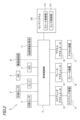
- FIG. 2 is a block diagram of the vehicle system 2 in which the sensor system 100 is incorporated.
- the vehicle system 2 includes a vehicle control unit 3, an internal sensor 5, an external sensor 6, a lamp 7, an HMI 8 (Human Machine Interface), a GPS 9 (Global Positioning System), and wireless communication. 10 and a map information storage unit 11 .
- the vehicle system 2 includes a steering actuator 12 , a steering device 13 , a brake actuator 14 , a brake device 15 , an accelerator actuator 16 and an accelerator device 17 .
- a sensor system 100 having a cleaner control section 113 and a sensor control section 114 is communicably connected to the vehicle control section 3 of the vehicle system 2 .
- the vehicle control unit 3 is composed of an electronic control unit (ECU).
- the vehicle control unit 3 includes a processor such as a CPU (Central Processing Unit), a ROM (Read Only Memory) storing various vehicle control programs, and a RAM (Random Access Memory) temporarily storing various vehicle control data. It is composed of The processor develops on the RAM programs designated from various vehicle control programs stored in the ROM, and is configured to execute various processes in cooperation with the RAM.
- the vehicle control unit 3 is configured to control travel of the vehicle 1 .
- the internal sensor 5 is a sensor capable of acquiring information on the own vehicle.
- the internal sensor 5 is, for example, at least one of an acceleration sensor, speed sensor, wheel speed sensor, gyro sensor, and the like.
- the internal sensor 5 is configured to acquire information of the own vehicle including the running state of the vehicle 1 and output the information to the vehicle control section 3 and the cleaner control section 113 .
- the internal sensors 5 include a seating sensor that detects whether or not the driver is sitting in the driver's seat, a face direction sensor that detects the direction of the driver's face, and a human sensor that detects whether or not there is a person inside the vehicle. may
- the external sensor 6 is a sensor capable of acquiring information on the outside of the own vehicle.
- the external sensor is, for example, at least one of camera, radar, LiDAR, and the like.
- the external sensor 6 acquires information on the outside of the own vehicle including the surrounding environment of the vehicle 1 (other vehicles, pedestrians, road shape, traffic signs, obstacles, etc.), and transmits the information to the vehicle control unit 3 and the cleaner control unit. 113 and the sensor control unit 114 .
- the external sensor 6 may include a weather sensor that detects weather conditions, an illuminance sensor that detects the illuminance of the surrounding environment of the vehicle 1, or the like.
- the camera is a camera including an imaging device such as CCD (Charge-Coupled Device) or CMOS (Complementary MOS).
- the camera is a camera that detects visible light or an infrared camera that detects infrared light.
- the radar is millimeter wave radar, microwave radar, laser radar, or the like.
- LiDAR is an abbreviation for Light Detection and Ranging or Laser Imaging Detection and Ranging.
- LiDAR is a sensor that generally emits invisible light in front of it and acquires information such as the distance to an object, the direction of the object, the shape of the object, and the material of the object based on the emitted light and the returned light.
- the lamps 7 include head lamps and position lamps provided at the front of the vehicle 1, rear combination lamps provided at the rear of the vehicle 1, turn signal lamps provided at the front or side of the vehicle, pedestrians and drivers of other vehicles. It is at least one of various lamps or the like for informing the driver of the situation of the own vehicle.
- the HMI 8 is composed of an input section that receives input operations from the driver and an output section that outputs driving information and the like to the driver.
- the input unit includes a steering wheel, an accelerator pedal, a brake pedal, an operation mode switch for switching the operation mode of the vehicle 1, and the like.
- the output unit is a display that displays various running information.
- the GPS 9 is configured to acquire current position information of the vehicle 1 and output the acquired current position information to the vehicle control unit 3 .
- the wireless communication unit 10 is configured to receive travel information of other vehicles around the vehicle 1 from other vehicles and to transmit travel information of the vehicle 1 to the other vehicles (vehicle-to-vehicle communication). Further, the wireless communication unit 10 is configured to receive infrastructure information from infrastructure equipment such as traffic lights and marker lights, and to transmit travel information of the vehicle 1 to the infrastructure equipment (road-to-vehicle communication).
- the map information storage unit 11 is an external storage device such as a hard disk drive storing map information, and is configured to output the map information to the vehicle control unit 3 .
- the vehicle control unit 3 When the vehicle 1 runs in the automatic driving mode, the vehicle control unit 3 generates at least a steering control signal, an accelerator control signal, and a brake control signal based on the running state information, the surrounding environment information, the current position information, the map information, and the like. Automatically generate one.
- the steering actuator 12 is configured to receive a steering control signal from the vehicle control unit 3 and control the steering device 13 based on the received steering control signal.
- the brake actuator 14 is configured to receive a brake control signal from the vehicle control unit 3 and control the brake device 15 based on the received brake control signal.
- the accelerator actuator 16 is configured to receive an accelerator control signal from the vehicle control unit 3 and control the accelerator device 17 based on the received accelerator control signal.
- the running of the vehicle 1 is automatically controlled by the vehicle system 2 .
- the vehicle control unit 3 when the vehicle 1 runs in manual operation mode, the vehicle control unit 3 generates a steering control signal, an accelerator control signal and a brake control signal in accordance with the driver's manual operations on the accelerator pedal, brake pedal and steering wheel.
- the steering control signal, the accelerator control signal and the brake control signal are generated by the driver's manual operation, so that the driving of the vehicle 1 is controlled by the driver.
- the sensor system 100 of the vehicle 1 has, as external sensors 6, a front LiDAR 6f, a rear LiDAR 6b, a left LiDAR 6l, and a right LiDAR 6r.
- the front LiDAR 6f is configured to acquire information ahead of the vehicle 1 .
- the rear LiDAR 6 b is configured to acquire information behind the vehicle 1 .
- the left LiDAR 6 l is configured to obtain information on the left side of the vehicle 1 .
- the right LiDAR 6r is configured to obtain information on the right side of the vehicle 1 .
- the front LiDAR 6f is provided at the front of the vehicle 1
- the rear LiDAR 6b is provided at the rear of the vehicle 1
- the left LiDAR 6l is provided at the left of the vehicle 1
- the right LiDAR 6r is provided at the front of the vehicle 1.
- a front LiDAR, a rear LiDAR, a left LiDAR, and a right LiDAR may be collectively arranged on the ceiling of the vehicle 1 .
- the sensor system 100 also has, as the lamps 7, a left headlamp 7l provided on the left side of the front of the vehicle 1 and a right headlamp 7r provided on the same right side. Furthermore, the sensor system 100 has a front window 1f and a rear window 1b as window shields.
- the sensor system 100 also includes a cleaner unit 110 (detailed with reference to FIG. 3) that removes foreign matter such as water droplets, mud, dust, etc. from the object to be cleaned, or prevents foreign matter from adhering to the object to be cleaned.
- the cleaner unit 110 includes a front window washer (hereinafter referred to as front WW) 101 capable of cleaning the front window 1f and a rear window washer (hereinafter referred to as rear WW) capable of cleaning the rear window 1b. ) 102 .
- the cleaner unit 110 also has a front sensor cleaner (hereinafter referred to as front SC) 103 capable of cleaning the front LiDAR 6f and a rear sensor cleaner (hereinafter referred to as rear SC) 104 capable of cleaning the rear LiDAR 6b. .
- the cleaner unit 110 also has a right sensor cleaner (hereinafter referred to as right SC) 105 capable of cleaning the right LiDAR 6r and a left sensor cleaner (hereinafter referred to as left SC) 106 capable of cleaning the left LiDAR 6l. .
- the cleaner unit 110 includes a right headlamp cleaner (hereinafter referred to as a right HC) 107 capable of cleaning the right headlamp 7r and a left headlamp cleaner (hereinafter referred to as a left HC) capable of cleaning the left headlamp 7l. 108.
- a right headlamp cleaner hereinafter referred to as a right HC
- a left headlamp cleaner hereinafter referred to as a left HC
- Each of the cleaners 101 to 108 has one or more nozzles, and jets a cleaning medium such as high-pressure air or cleaning liquid toward an object from an injection port provided in the nozzle.
- FIG. 3 is a block diagram of the cleaner unit 110 included in the sensor system 100.
- the cleaner unit 110 has a tank 111, a pump 112, a cleaner control section 113, and air pumps 115-118 in addition to the cleaners 101-108.
- Front WW 101 , rear WW 102 , right HC 107 and left HC 108 are connected to tank 111 via pump 112 .
- the pump 112 sucks the cleaning liquid (an example of cleaning medium) stored in the tank 111 and transfers it to the front WW101, the rear WW102, the right HC107, and the left HC108.
- Air pumps 115 to 118 are connected to the front SC 103, rear SC 104, right SC 105, and left SC 106, respectively. Each of the air pumps 115-118 generates high pressure air (an example of cleaning medium) and sends the generated high pressure air to the front SC103, rear SC104, right SC105 and left SC106.
- high pressure air an example of cleaning medium
- Each of the cleaners 101 to 108 may be provided with an actuator (not shown) that opens the nozzle provided in each cleaner to spray the cleaning medium onto the object to be cleaned.
- the actuators provided in each of the cleaners 101-108 are electrically connected to the cleaner control section 113.
- FIG. A pump 112 and air pumps 115 to 118 are also electrically connected to the cleaner control section 113 .
- the operations of the cleaners 101-108, the pump 112, the air pumps 115-118, etc. are controlled by the cleaner control section 113.
- the cleaner control section 113 is electrically connected to the vehicle control section 3 and the sensor control section 114 (see FIG. 2).
- the information acquired by the cleaner control unit 113, the information acquired by the sensor control unit 114, and the information acquired by the vehicle control unit 3 are transmitted and received among the respective control units.
- the configurations of the cleaners 101-108 will be described in more detail with reference to FIGS. 4-16.
- the front SC 103 that cleans the front LiDAR 6f provided at the front of the vehicle 1 will be described. Note that the cleaners other than the front SC 103 have the same configuration, so the description thereof is omitted.
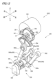
- FIG. 4 is a perspective view of the front SC103A.
- FIG. 5 is a perspective view showing the internal mechanism with the housing 160 (described later) of the front SC 103A shown in FIG. 4 removed.
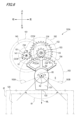
- FIG. 6 is a front view showing the internal mechanism and housing 160 of the front SC 103A shown in FIG.
- the front SC 103A includes a nozzle 130, a motor 140 that rotates the nozzle 130, a transmission mechanism 150 provided between the motor 140 and the nozzle 130, the motor 140 and the transmission mechanism. and a housing 160 containing 150 .
- the front SC 103A is arranged in the upper central portion of the front LiDAR 6f.
- the front LiDAR 6f has a rectangular front lens portion 120, which is the surface to be cleaned, in the central portion of its front surface.
- the nozzle 130 is provided directly above the front LiDAR 6f so as to extend toward the front lens portion 120 of the front LiDAR 6f.
- the nozzle 130 has an ejecting portion 131 extending in the vertical direction and a pipe line 132 extending in the front-rear direction.
- the nozzle 130 is configured to rotate around a rotation axis X2 extending in the front-rear direction through the center of the conduit 132 .
- the injection part 131 has an injection port 133 for injecting high-pressure air toward the front lens part 120 .
- the injection port 133 is formed on the lower surface of the injection portion 131 .
- the direction of the jetting port 133 is adjusted so that the high-pressure air jetted from the jetting port 133 is jetted downward from above the front lens portion 120 .
- the conduit 132 is connected to the back surface of the injection section 131 . As shown in FIG. 5, the conduit 132 is provided along the rotational axis X2 of the nozzle 130. As shown in FIG. An external pipeline (not shown) is connected to the rear end portion 132a of the pipeline 132, and high-pressure air is supplied from the air pump 115 via the external pipeline. The conduit 132 supplies high-pressure air supplied from the air pump 115 to the injection section 131 .
- the motor 140 is a motor capable of forward and reverse rotation.
- the motor 140 is provided so that the rotating shaft X1 extends in the front-rear direction.
- the direction of the rotation axis X ⁇ b>1 of the motor 140 matches the direction of the rotation axis X ⁇ b>2 of the nozzle 130 .
- Motor 140 is electrically connected to cleaner control unit 113 .
- the operation of the motor 140 is controlled by the cleaner control section 113 .
- the transmission mechanism 150 includes a motor gear 151 attached to the motor 140, a nozzle gear 154 attached to the nozzle 130, and driven gears 152 and 153 provided between the motor gear 151 and the nozzle gear 154. there is Transmission mechanism 150 is configured to transmit the rotational force of motor 140 to nozzle 130 .
- the motor gear 151 is attached to the output shaft 141 of the motor 140 .
- the motor gear 151 rotates together with the output shaft 141 of the motor 140 as the output shaft 141 rotates.
- the nozzle gear 154 is attached to the conduit 132 of the nozzle 130 .
- the nozzle gear 154 is provided in a portion of the pipe line 132 in the circumferential direction, and is formed in, for example, a fan shape when viewed from the direction of the rotation axis X2 of the nozzle 130 .
- the nozzle gear 154 is formed to have a fan shape centered on the direction directly above the pipeline 132 .
- a fan-shaped center angle ⁇ 2 (see FIG. 6) of the nozzle gear 154 is set to an angle corresponding to the rotation range of the injection portion 131 of the nozzle 130 .
- the fan-shaped center angle ⁇ 2 of the nozzle gear 154 allows the injection portion 131 to swing forward and backward, and the injection axis ML of the high-pressure air injected from the injection port 133 to move within the range of the predetermined movable angle ⁇ 1.
- the predetermined movable angle ⁇ 1 is set to an angle such that the high-pressure air jetted from the jet port 133 is jetted from the left end region to the right end region of the front lens portion 120 of the front LiDAR 6f.
- the driven gears 152 and 153 are configured to rotate around a rotation axis X3 extending in the front-rear direction.
- the driven gears 152 and 153 are stacked on the rotating shaft X3 in the front-rear direction.
- the driven gear 152 has a larger diameter than the driven gear 153 .
- a driven gear 152 is provided on the rear side of the rotation axis X3, and a driven gear 153 is provided on the front side of the rotation axis X3.
- the direction of the rotation axis X3 coincides with the direction of the rotation axis X1 of the motor 140 and the direction of the rotation axis X2 of the nozzle .
- the driven gear 152 is provided so as to mesh with the motor gear 151 of the motor 140 .
- a driven gear 153 (an example of a first gear) is provided so as to mesh with a nozzle gear 154 (an example of a second gear) of the nozzle 130 .
- the driven gears 152 and 153 rotate in forward and reverse directions as the motor 140 rotates forward and backward by meshing the driven gear 152 with the motor gear 151 .
- the driven gears 152 and 153 rotate the nozzle gear 154 in forward and reverse directions as the motor 140 rotates forward and backward by meshing the driven gear 153 with the nozzle gear 154 .
- the housing 160 has a motor housing 161 that houses the motor 140 and the motor gear 151 , a driven gear housing 162 that houses the driven gears 152 and 153 , and a nozzle gear housing 163 that houses the nozzle gear 154 .
- the motor housing 161, the driven gear housing 162 and the nozzle gear housing 163 are integrally formed.
- the nozzle gear housing 163 is formed to have a sector shape when viewed from the direction of the rotation axis X2 of the nozzle 130.
- a fan-shaped center angle ⁇ 3 (see FIG. 6) of the nozzle gear housing 163 is set to an angle corresponding to a rotation range of the nozzle gear 154 in the forward and reverse directions along the circumferential direction of the pipe line 132 . That is, the nozzle gear housing 163 is set to have a center angle ⁇ 3 so as to have an internal space S necessary for accommodating the nozzle gear 154 that rotates in forward and reverse directions.
- the nozzle gear housing 163 has inner wall surfaces 163A and 163B that define a central angle ⁇ 3 in the left and right downward direction. Each inner wall surface 163A, 163B functions as an abutment surface that contacts the nozzle gear 154, thereby defining the movable range of the nozzle gear 154. As shown in FIG.
- the front SC 103A with such a configuration operates as follows. For example, as shown in FIG. 6, in the front view of the front SC 103A, when the motor gear 151 rotates clockwise as indicated by the arrow CW as the motor 140 rotates, the driven gear 152 meshing with the motor gear 151 rotates in the opposite direction indicated by the arrow CCW. Rotate clockwise. When the driven gear 152 rotates counterclockwise, the driven gear 153 also rotates counterclockwise along with the rotation of the driven gear 152 . When the driven gear 153 rotates counterclockwise, the nozzle gear 154 meshing with the driven gear 153 rotates clockwise as indicated by arrow CW.
- the nozzle gear 154 rotates clockwise, the nozzle 130 also rotates clockwise along with the rotation of the nozzle gear 154 .
- the injection part 131 of the nozzle 130 rotates clockwise about the rotation axis X2, and the direction of the injection port 133 of the injection part 131 with respect to the front lens part 120 of the front LiDAR 6f is changed rightward.
- the nozzle gear 154 can rotate clockwise until it abuts against the inner wall surface 163 ⁇ /b>B on the left side of the nozzle gear housing 163 .
- the driven gears 152 and 153 rotate clockwise.
- the nozzle gear 154 rotates counterclockwise, and the nozzle 130 to which the nozzle gear 154 is attached also rotates counterclockwise like the nozzle gear 154 .
- the injection part 131 of the nozzle 130 rotates counterclockwise about the rotation axis X2, and the direction of the injection hole 133 of the injection part 131 with respect to the front lens part 120 of the front LiDAR 6f is changed to the clockwise direction. to the left in the opposite direction.
- the nozzle gear 154 can rotate counterclockwise until it abuts against the right inner wall surface 163 A of the nozzle gear housing 163 .
- the rotational driving force of the motor 140 is transmitted to the nozzle 130 by the transmission mechanism 150, and the injection part 131 of the nozzle 130 is repeatedly movable in the forward and backward directions within the range of the movable angle ⁇ 1. reciprocate.
- the direction of the injection port 133 of the injection portion 131 is changed, the position of the injection axis ML of the injection port 133 is changed, and the high-pressure air injected from the injection port 133 is directed to the left end region of the front lens portion 120 of the front LiDAR 6f. to the right end region.
- the front SC 103A (an example of a cleaner) of this embodiment includes a nozzle 130 having an injection port 133 that injects high-pressure air (an example of a cleaning medium), and a motor 140 that can rotate in at least one direction. , and a transmission mechanism 150 provided between the motor 140 and the nozzle 130 .
- the transmission mechanism 150 transmits the rotational force of the motor 140 to the nozzle 130 to reciprocate the nozzle 130 to change the position of the injection axis ML of the injection port 133 with respect to the front lens portion 120 of the front LiDAR 6f, which is the surface to be cleaned.
- the nozzle 130 can be reciprocated by the rotation of the motor 140 to change the position of the ejection axis ML, so that the front lens portion 120 can be efficiently cleaned over a wide range.
- the nozzle 130 has a conduit 132 extending along the rotation axis X2 of the nozzle 130 in order to supply high pressure air to the injection port 133 .
- the transmission mechanism 150 includes a driven gear 153 (an example of a first gear) that rotates in forward and reverse directions by the motor 140, and a nozzle gear 154 (an example of a second gear) that rotates in the forward and backward directions by meshing with the driven gear 153. consists of at least The nozzle gear 154 is provided in a part of the pipe line 132 in the circumferential direction. According to this configuration, the transmission mechanism 150 capable of realizing the reciprocating motion of the nozzle 130 can be configured with a small number of parts.
- the nozzle gear 154 is formed in a fan shape. According to this configuration, the nozzle gear 154 can be formed compactly according to the range of reciprocating motion of the nozzle 130, leading to miniaturization of the front SC 103A.
- the front SC 103A of this embodiment further includes a housing 160 that houses at least the motor 140 and the transmission mechanism 150.
- a nozzle gear housing 163 that accommodates the nozzle gear 154 in the housing 160 has inner wall surfaces 163A and 163B that define the movable range of the nozzle gear 154 along the circumferential direction. According to this configuration, since the movable range of the nozzle gear 154 can be restricted to a predetermined range by the inner wall surfaces 163A and 163B of the nozzle gear housing 163, it is possible to prevent the nozzle gear 154 and the driven gear 153 from coming out of mesh when the motor 140 rotates. can.
- the direction of the rotation axis X1 of the motor 140 coincides with the direction of the rotation axis X2 of the nozzle .
- the reciprocating motion of the nozzle 130 can be realized with a smaller number of parts, and the entire front SC 103A can be made smaller.
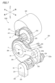
- FIG. 7 is a perspective view of the front SC103B.
- 8 is a front view of the front SC 103B shown in FIG. 7.
- FIG. 9 to 11 are diagrams for explaining the operation of the pre-SC 103B.
- the front SC 103B has a nozzle 230, a motor 240 for rotating the nozzle 230, and a transmission mechanism 250 provided between the motor 240 and the nozzle 230.
- the front SC 103B is arranged in the upper central portion of the front LiDAR 6f, like the front SC 103A of the first embodiment.
- the nozzle 230 has a vertically extending jet portion 231 and a longitudinally extending pipe line 232 .
- An injection port 233 is provided in the injection portion 231 .
- a connecting portion 234 that connects to the transmission mechanism 250 is provided in the pipeline 232 .
- the connecting portion 234 is provided with a cylindrical projecting portion 234a projecting forward.
- the configurations of the injection part 231, the pipe line 232, and the injection port 233 of the nozzle 230 are the same as the corresponding parts of the nozzle 130 in the first embodiment.
- the motor 240 of the front SC 103B according to the second embodiment is configured to rotate only in one of forward and reverse directions. Other configurations of the motor 240 are the same as those of the motor 140 of the first embodiment.
- the transmission mechanism 250 includes a motor gear 251 attached to the motor 240, a drive gear 254 (an example of a third gear) connected to the nozzle 230, and a driven gear provided between the motor gear 251 and the drive gear 254.
- 252 and 253 (an example of a fourth gear) and a link member 255 (an example of a first link member) provided between the drive gear 254 and the nozzle 230 .
- Transmission mechanism 250 is configured to transmit the rotational force of motor 240 to nozzle 230 .
- the motor gear 251 is attached to the output shaft 241 of the motor 240 .
- the motor gear 251 rotates together with the output shaft 241 of the motor 240 as the output shaft 241 rotates.
- the drive gear 254 is a gear that drives the nozzle 230 .
- Drive gear 254 is connected to nozzle 230 via link member 255 .
- the drive gear 254 is configured to rotate around a rotation axis X4 extending in the front-rear direction.
- the direction of the rotation axis X4 coincides with the direction of the rotation axis X1 of the motor 240 and the direction of the rotation axis X2 of the nozzle 230 .
- a front surface of the driving gear 254 is formed integrally with the driving gear 254 with a cylindrical circular step portion 264 protruding forward.
- the circular stepped portion 264 has a diameter smaller than that of the drive gear 254 , and its center P is formed eccentrically from the position of the rotation axis X 4 which is the center of the drive gear 254 .
- a link member 255 is a member that connects the driving gear 254 to the nozzle 230 .
- the link member 255 includes a gear link portion 255a connected to the driving gear 254, a nozzle link portion 255c connected to the nozzle 230, and a communication portion 255b provided between the gear link portion 255a and the nozzle link portion 255c. ing.
- the gear link portion 255a is provided at one end of the link member 255 on the drive gear 254 side.
- the gear link portion 255a is formed in a cylindrical body.
- the gear link portion 255a is configured to be connected to the driving gear 254 by accommodating the circular stepped portion 264 of the driving gear 254 in the inner space of the cylindrical body.
- the nozzle link portion 255c is provided at one end of the link member 255 on the nozzle 230 side opposite to the gear link portion 255a.
- the nozzle link portion 255c is formed in a cylindrical body.
- the nozzle link portion 255c is configured to be connected to the nozzle 230 by accommodating the projecting portion 234a provided on the connecting portion 234 of the nozzle 230 in the internal space of the cylindrical body.
- the communicating portion 255b is a member that connects the gear link portion 255a and the nozzle link portion 255c.
- the communication part 255b is formed in a plate shape or a bar shape, for example.
- the link member 255 which accommodates the circular stepped portion 264 of the drive gear 254 in the internal space of the gear link portion 255a, is configured to be rotatable around the circular stepped portion 264 in the circumferential direction.
- the central axis X5 of rotation of the gear link portion 255a is provided eccentrically from the rotation axis X4 of the driving gear 254. As shown in FIG.
- the central axis X5 of the gear link portion 255a coincides with the position of the center P of the circular stepped portion 264 of the drive gear 254. As shown in FIG.
- the link member 255 which accommodates the projecting portion 234a of the connecting portion 234 of the nozzle 230 in the internal space of the nozzle link portion 255c, is configured to be rotatable in the circumferential direction around the projecting portion 234a.
- the driven gear 252 is provided so as to mesh with the motor gear 251 of the motor 240 .
- the driven gear 253 is provided so as to mesh with the driving gear 254 .
- the driven gears 252 and 253 rotate in one direction as the motor 240 rotates in one direction by meshing the driven gear 252 with the motor gear 251 . Further, the driven gears 252 and 253 transmit the unidirectional rotational force of the motor 240 to the driving gear 254 to rotate the driving gear 254 in one direction by the driven gear 253 meshing with the driving gear 254 .
- the front SC 103B with such a configuration operates as follows. For example, as shown in FIG. 8, from a state in which the injection part 231 of the nozzle 230 faces directly downward, as shown in FIG.
- the driven gear 252 meshing with the motor gear 251 rotates counterclockwise as indicated by arrow CCW.
- the driven gear 252 rotates counterclockwise
- the driven gear 253 also rotates counterclockwise along with the rotation.
- the driving gear 254 meshing with the driven gear 253 rotates clockwise as indicated by arrow CW.
- the circular stepped portion 264 changes its position in the direction of approaching the connecting portion 234 of the nozzle 230 along with the rotation.
- the injection part 231 of the nozzle 230 rotates counterclockwise around the rotation axis X2, and the direction of the injection hole 233 of the injection part 231 with respect to the front lens part 120 of the front LiDAR 6f changes to the left direction this time. do.
- the rotational driving force of the motor 240 is transmitted to the nozzle 230 by the transmission mechanism 250, and the injection portion 231 of the nozzle 230 repeats forward and reverse within a predetermined movable range. reciprocate.
- the direction of the injection port 233 of the injection portion 231 is changed, the position of the injection axis ML of the injection port 233 is changed, and the high-pressure air injected from the injection port 233 is directed to the left end region of the front lens portion 120 of the front LiDAR 6f. to the right end region.
- the transmission mechanism 250 includes the drive gear 254 (an example of the third gear) that rotates in one direction as the motor 240 rotates in one direction, and the drive gear 254 at one end. and a link member 255 (an example of a first link member) attached to the nozzle 230 at the other end thereof.
- a cylindrical gear link portion 255 a is formed at one end of the link member 255 , and the central axis X 5 of the gear link portion 255 a is eccentric from the rotation axis X 4 of the drive gear 254 .
- a circular stepped portion 264 is formed on one side surface of the drive gear 254 and accommodated in the internal space of the gear link portion 255a of the link member 255.
- the center P of the circular stepped portion 264 is It is eccentric from the rotation axis X4 of the drive gear 254 .
- the center axis X5 of the gear link portion 255a of the link member 255 and the rotation axis X4 of the driving gear 254 can be eccentric with a simple configuration.
- the front SC 103B of the present embodiment includes driven gears 252 and 253 (an example of a fourth gear) arranged between the motor 240 and the driving gear 254 to transmit the unidirectional rotation of the motor 240 to the driving gear 254. ) is further provided. According to this configuration, the nozzle 230 can be rotated without using the high-torque motor 240, so the motor 240 can be downsized.
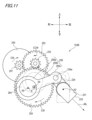
- FIG. 12 is a perspective view of the front SC103C.
- 13 is a front view of the front SC 103C shown in FIG. 12.
- FIG. 14 and 15 are diagrams for explaining the operation of the pre-SC 103C.
- the front SC 103C has a nozzle 330, a motor 340 that rotates the nozzle 330, and a transmission mechanism 350 provided between the motor 340 and the nozzle 330.
- the front SC 103C is arranged in the upper central portion of the front LiDAR 6f, like the front SC 103A of the first embodiment.
- the nozzle 330 has an ejecting portion 331 extending in the vertical direction and a pipe line 332 extending in the front-rear direction.
- An injection port 333 is provided in the injection portion 331 .
- Connecting portions 334 , 335 , and 336 that connect to the transmission mechanism 350 are provided in the pipeline 332 .
- the connecting portions 334 , 335 , and 336 are provided above, on the right side, and on the left side of the pipe 332 in parallel with different positions in the longitudinal direction (front-rear direction) of the pipe 332 .
- the connecting portions 334, 335 and 336 are provided with columnar projecting portions 334a, 335a and 336a projecting forward or backward, respectively.
- the configurations of the injection part 331, the pipe line 332, and the injection port 333 of the nozzle 330 are the same as the corresponding parts of the nozzle 130 in the first embodiment.
- the motor 340 is a motor having the same configuration as the motor 140 of the first embodiment.
- the transmission mechanism 350 includes a motor gear 351 attached to the motor 340, a driving gear 354 (an example of a fifth gear) connected to the nozzle 330, and a driven gear provided between the motor gear 351 and the driving gear 354. 352, 353, and a link member 355 (an example of a second link member) connected between the driving gear 354 and the nozzle 330. Transmission mechanism 350 is configured to transmit the rotational force of motor 340 to nozzle 330 .
- the motor gear 351 and driven gears 352 and 353 are gears having configurations similar to the motor gear 151 and driven gears 152 and 153 of the first embodiment, respectively.
- the drive gear 354 is formed to have a sector shape when viewed from the front side of the front SC 103C, and meshes with the driven gear 353 to rotate in the forward and reverse directions as the motor 340 rotates forward and backward. It is the same as the configuration of the nozzle gear 154 in the first embodiment.
- the drive gear 354 is further provided with a connecting portion 354 a that connects with the link member 355 .
- the drive gear 354 is a gear that rotates the nozzle 330 via the link member 355 .
- the link member 355 includes an upper link member 355a attached above the nozzle 330, a right link member 355b attached to the right side of the nozzle 330, and a left link member 355c attached to the left side of the nozzle 330. have.
- One end of the upper link member 355 a is attached to the connecting portion 334 of the nozzle 330 , and the other end opposite to the nozzle 330 side is attached to the link fixing point 361 .
- One end of the upper link member 355a is, for example, cylindrical.
- the upper link member 355a is rotatably attached to the connecting portion 334 with the projecting portion 334a of the connecting portion 334 accommodated in the inner space of the cylindrical body forming the one end.
- the nozzle 330 is configured to be rotatable around a projecting portion 334 a of the connecting portion 334 .
- the other end of the upper link member 355a is, for example, cylindrical.
- the upper link member 355a is fixed to the link fixing point 361 in a state in which the link fixing point 361 is accommodated in the inner space of the cylindrical body forming the other end.
- One end of the right link member 355 b is attached to the connecting portion 335 of the nozzle 330 , and the other end opposite to the nozzle 330 side is attached to the connecting portion 354 a of the driving gear 354 .
- One end of the right link member 355b is, for example, cylindrical.
- the right link member 355b is attached to the connecting portion 335 with the projecting portion 335a of the connecting portion 335 accommodated in the internal space of the cylindrical body forming the one end.
- the right link member 355b is configured to be rotatable around the projecting portion 335a of the connecting portion 335. As shown in FIG.
- the other end of the right link member 355b is, for example, cylindrical.
- the right link member 355b is fixed to the connecting portion 354a with the connecting portion 354a of the drive gear 354 accommodated in the internal space of the cylindrical body forming the other end.
- One end of the left link member 355 c is attached to the connecting portion 336 of the nozzle 330 , and the other end on the side opposite to the nozzle 330 side is attached to the link fixing point 362 .
- One end of the left link member 355c is, for example, cylindrical.
- the left link member 355c is attached to the connecting portion 336 with the projecting portion 336a of the connecting portion 336 housed in the internal space of the cylindrical body forming the one end.
- the left link member 355c is configured to be rotatable around the projecting portion 336a of the connecting portion 336. As shown in FIG.
- the other end of the left link member 355c is, for example, cylindrical.
- the left link member 355c is attached to the link fixing point 362 in a state in which the link fixing point 362 is accommodated within the internal space of the cylindrical body forming the other end.
- the left link member 355c is configured to be rotatable around the link fixing point 362. As shown in FIG.
- the pre-SC103C with such a configuration operates as follows. For example, as shown in FIG. 13, from a state in which the injection part 331 of the nozzle 330 faces straight down, as shown in FIG. When rotated counterclockwise, the driven gear 352 meshing with the motor gear 351 rotates clockwise as indicated by arrow CW. When the driven gear 352 rotates clockwise, the driven gear 353 also rotates clockwise along with the rotation. When the driven gear 353 rotates clockwise, the drive gear 354 meshing with the driven gear 353 rotates counterclockwise as indicated by arrow CCW.
- the right link member 355b rotates counterclockwise about the coupling portion 354a along with the rotation, and pushes the nozzle 330 through the coupling portion 335.
- the nozzle 330 rotates counterclockwise around the projecting portion 334a of the connecting portion 334, and the direction of the injection port 333 of the injection portion 331 with respect to the front lens portion 120 of the front LiDAR 6f changes leftward.
- the left link member 355c rotates counterclockwise as the nozzle 330 rotates, and restricts the amount of rotation of the nozzle 330 so that it does not exceed a predetermined movable range.
- the motor gear 351 rotates as shown in FIG. 15 as the motor 340 rotates.
- driven gears 352 and 353 rotate counterclockwise as indicated by arrow CCW.
- the driven gear 353 rotates counterclockwise
- the drive gear 354 meshing with the driven gear 353 rotates clockwise as indicated by arrow CW.
- the right link member 355b rotates clockwise about the coupling portion 354a along with the rotation, and draws the nozzle 330 through the coupling portion 335 .
- the nozzle 330 rotates clockwise around the projecting portion 334a of the connecting portion 334, and the direction of the injection port 333 of the injection portion 331 with respect to the front lens portion 120 of the front LiDAR 6f changes rightward.
- the left link member 355c rotates clockwise along with the rotation of the nozzle 330, and restricts the rotation of the nozzle 330 so that the amount of rotation does not exceed a predetermined movable range.
- the rotational driving force of the motor 340 is transmitted to the nozzle 330 by the transmission mechanism 350, and the injection portion 331 of the nozzle 330 reciprocates repeatedly within a predetermined movable range in the forward and backward directions. move.
- the orientation of the injection port 333 of the injection portion 331 is changed, the position of the injection axis ML of the injection port 333 is changed, and the high-pressure air injected from the injection port 333 is directed to the left end region of the front lens portion 120 of the front LiDAR 6f. to the right end region.
- the transmission mechanism 350 includes the driving gear 354 (an example of the fifth gear) that rotates forward and backward by the motor 340, and one end of each gear is attached to the nozzle 330. and a plurality of link members 355 (an example of a second link member).
- the driving gear 354 an example of the fifth gear
- the right link member 355b is connected to the drive gear 354 at the other end.
- the left link member 355c is configured so that the other end can rotate about the link fixing point 362. As shown in FIG. According to this configuration, the transmission mechanism 350 capable of realizing the reciprocating motion of the nozzle 330 can be easily configured.
- the plurality of link members 355 includes an upper link member 355a, a right link member 355b, and a left link member 355c arranged in parallel. are provided respectively. According to this configuration, the rotation mechanism of the nozzle 330 can be realized without the upper link member 355a, the right link member 355b, and the left link member 355c interfering with each other.
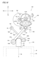
- FIG. 16 is a configuration diagram showing the transmission mechanism 450 of the front SC 103D according to the fourth embodiment.
- the transmission mechanism 450 of the front SC 103D includes a motor gear 451 attached to the motor 440, a drive gear 454 connected to the nozzle 430, and provided between the motor gear 451 and the drive gear 454. and a link member 455 connected between the driving gear 454 and the nozzle 430 .
- a motor gear 451, driven gears 452, 453, and a drive gear 454 are gears having configurations similar to the motor gear 351, driven gears 352, 353, and drive gear 354 of the third embodiment, respectively.
- the link member 455 is composed of a right link member 455 a attached to the right side of the nozzle 430 and a left link member 455 b attached to the left side of the nozzle 430 .
- the right link member 455 a has one end attached to the connecting portion 435 of the nozzle 430 and the other end opposite to the nozzle 430 side attached to the connecting portion 454 a of the driving gear 454 .
- One end of the right link member 455a is formed in, for example, a cylindrical body, and is attached to the connecting part 435 with the projecting part 435a of the connecting part 435 accommodated in the inner space of the cylindrical body.
- the right link member 455a is configured to be rotatable around the projecting portion 435a of the connecting portion 435.
- the other end of the right link member 455a is formed, for example, into a cylindrical body, and is fixed to the connecting part 454a in a state in which the connecting part 454a of the drive gear 454 is accommodated in the inner space of the cylindrical body.
- the left link member 455b has one end attached to the connecting portion 436 of the nozzle 430 and the other end opposite to the nozzle 430 side attached to the link fixing point 461 .
- One end of the left link member 455b is formed, for example, into a cylindrical body, and is attached to the connecting part 436 with the projecting part 436a of the connecting part 436 accommodated in the internal space of the cylindrical body.
- the projecting portion 436a of the connecting portion 436 is rotatably accommodated in the inner space of one end of the left link member 455b.
- the other end of the left link member 455b is formed in a cylindrical body, for example, and is attached to the link fixing point 461 with the link fixing point 461 accommodated in the inner space of the cylindrical body.
- the left link member 455b is provided so as to cross the right link member 455a.
- the link fixing point 461 is provided at a position such that the left link member 455b and the right link member 455a are arranged to cross each other
- the front SC 103D with such a configuration operates as follows. For example, when the drive gear 454 rotates counterclockwise as the motor 440 rotates, the right link member 455a rotates counterclockwise around the connecting portion 454a. As the right link member 455 a rotates counterclockwise, the nozzle 430 rotates counterclockwise through the connecting portion 435 . As a result, the orientation of the injection port 433 of the injection unit 431 with respect to the front lens unit 120 of the front LiDAR 6f changes to the left. At this time, as the nozzle 430 rotates, the protruding portion 436a of the connecting portion 436 rotates counterclockwise in the inner space of one end of the left link member 455b. counterclockwise rotation.
- the right link member 455a rotates clockwise about the connecting portion 454a along with the rotation.
- the nozzle 430 rotates clockwise through the connecting portion 435 .
- the orientation of the injection port 433 of the injection unit 431 with respect to the front lens unit 120 of the front LiDAR 6f changes rightward.
- the protruding portion 436a of the connecting portion 436 rotates clockwise in the inner space of one end of the left link member 455b. Assist clockwise rotation.
- the link member 455 of the transmission mechanism 450 in the front SC103D of the modified example is composed of the right link member 455a and the left link member 455b.
- One ends of the two link members are connected to the left and right sides of the nozzle 430, respectively, and the other ends of the two link members are fixed at positions where the two link members cross each other. According to this configuration, it is possible to clean a wider area of the front lens portion 120, which is the surface to be cleaned, with a smaller number of link members.
- the driven gear is provided between the motor gear and the nozzle gear, or between the motor gear and the drive gear has been described, but the invention is not limited to this.
- the nozzle gear or drive gear may be directly meshed with the motor gear without providing a driven gear.
- FIG. 17 is a perspective view of the front SC503.
- 18 is a front view of the front SC 503 shown in FIG. 17.
- the front SC 503 has a nozzle 530, a motor 540 for rotating the nozzle 530, and a gear mechanism 550 and a link mechanism 560 provided between the motor 540 and the nozzle 530. are doing.
- the front SC 503 is arranged in the upper central part of the front LiDAR 6f, as shown in FIG.
- the front LiDAR 6f has a rectangular front lens portion 120, which is the surface to be cleaned, in the central portion of its front surface.
- the rear part of the nozzle 530 of the front SC 503, the motor 540, the gear mechanism 550, and the link mechanism 560 are housed in a housing, and are configured to prevent water from entering from the outside of the housing. .
- illustration of the housing of the front SC 503 is omitted in FIG. 17 and the like.
- the nozzle 530 is provided directly above the front LiDAR 6f so as to extend toward the front lens portion 120 of the front LiDAR 6f.
- the nozzle 530 has an ejecting portion 531 extending in the vertical direction and a pipe line 532 extending in the front-rear direction.
- the injection part 531 has an injection port 533 for injecting high-pressure air toward the front lens part 120 .
- the injection port 533 is formed on the lower surface of the injection portion 531 .
- the direction of the jetting port 533 is adjusted so that the high-pressure air jetted from the jetting port 533 is jetted downward from above the front lens portion 120 .
- the conduit 532 is connected to the back surface of the injection section 531 .
- An external pipeline (not shown) is connected to the rear end portion 532a of the pipeline 532, and high-pressure air is supplied from the air pump 115 via the external pipeline.
- the conduit 532 supplies high-pressure air supplied from the air pump 115 to the injection section 531 .
- the pipeline 532 is provided with two connecting portions 534 and 535 that are connected to the link mechanism 560 .
- the connecting portions 534 and 535 are provided on the right side and the left side of the pipeline 532, respectively.
- the connecting portion 534 and the connecting portion 535 are provided in a state in which their positions are different from each other in the longitudinal direction (front-rear direction) of the pipeline 532 .
- the connecting portions 534 and 535 are provided with cylindrical projecting portions 534a and 535a projecting forward or backward, respectively.
- the motor 540 is a motor that can rotate in forward and reverse directions.
- the motor 540 is configured to rotate around a rotation axis X6 extending in the front-rear direction.
- Motor 540 is electrically connected to cleaner control unit 113 .
- the operation of the motor 540 is controlled by the cleaner control section 113 .
- the gear mechanism 550 includes a motor gear 551 attached to the motor 540, a driving gear 554 connected to the link mechanism 560, and driven gears 552 and 553 provided between the motor gear 551 and the driving gear 554. It is configured. Gear mechanism 550 is configured to transmit the rotational force of motor 540 to link mechanism 560 .
- the motor gear 551 is attached to the output shaft 541 of the motor 540 .
- the motor gear 551 rotates together with the output shaft 541 of the motor 540 as the output shaft 541 rotates.
- the drive gear 554 is attached to a connecting portion 554a (an example of a fixed point).
- the connecting portion 554a is provided so as to extend in the front-rear direction.
- the drive gear 554 is provided in a portion of the connecting portion 554a in the circumferential direction, and is formed to have a sector shape when viewed from the direction of the central axis X8 of the connecting portion 554a.
- the driving gear 554 is configured to rotate together with the connecting portion 554a about the central axis X8.
- the direction of the central axis X8 of the connecting portion 554a matches the direction of the rotation axis X6 of the motor 540. As shown in FIG.
- the driven gears 552 and 553 are configured to rotate around a rotation axis X7 extending in the front-rear direction.
- the driven gear 552 and the driven gear 553 are stacked in the front-rear direction on the rotating shaft X7.
- the driven gear 552 has a larger diameter than the driven gear 553 .
- a driven gear 552 is provided on the rear side of the rotation axis X7, and a driven gear 553 is provided on the front side of the rotation axis X7.
- the direction of the rotation axis X7 coincides with the direction of the rotation axis X6 of the motor 540 and the direction of the central axis X8 of the connecting portion 554a.
- the driven gear 552 is provided so as to mesh with a motor gear 551 attached to the motor 540 .
- the driven gear 553 is provided so as to mesh with the drive gear 554 attached to the connecting portion 554a.
- the driven gears 552 and 553 rotate in forward and reverse directions as the motor 540 rotates forward and backward by the driven gear 552 meshing with the motor gear 551 .
- the driven gears 552 and 553 rotate the driving gear 554 forward and backward in accordance with the forward and reverse rotation of the motor 540 by meshing the driven gear 553 with the driving gear 554 .
- the link mechanism 560 has a gear link member 561 (an example of a third link member) and an auxiliary link member 562 (an example of a fourth link member).
- a gear link member 561 is provided between the nozzle 530 and the driving gear 554 .
- the gear link member 561 includes a nozzle link portion 561a connected to the nozzle 530, a gear link portion 561c connected to the connection portion 554a to which the driving gear 554 is attached, and a shaft portion connecting the nozzle link portion 561a and the gear link portion 561c. 561b and .
- a nozzle link portion 561a and a gear link portion 561c of the gear link member 561 are formed in a cylindrical body.
- the nozzle link portion 561a is connected to the nozzle 530 so as to accommodate the projecting portion 534a of the connecting portion 534 of the pipe line 532 in the inner space of the cylindrical body.
- the nozzle link portion 561a is rotatable around the projecting portion 534a.
- the gear link portion 561c is fixed to the connecting portion 554a so as to accommodate the connecting portion 554a of the driving gear 554 in the inner space of the cylindrical body.
- the gear link portion 561c rotates about the central axis X8 together with the connecting portion 554a.
- the auxiliary link member 562 is provided between the nozzle 530 and a link fixing portion 563 (an example of a fixing point) arranged above the nozzle 530 .
- the auxiliary link member 562 has a nozzle link portion 562a connected to the nozzle 530, a fixed link portion 562c connected to the link fixing portion 563, and a shaft portion 562b connecting the nozzle link portion 562a and the fixed link portion 562c.
- the link fixing portion 563 is a cylindrical protruding member that protrudes forward. The direction of the central axis X9 of the link fixing portion 563 matches the direction of the central axis X8 of the connecting portion 554a.
- a nozzle link portion 562a and a fixed link portion 562c of the auxiliary link member 562 are formed in a cylindrical shape.
- the nozzle link portion 562a is connected to the nozzle 530 so as to accommodate the projecting portion 535a of the connecting portion 535 of the pipe line 532 in the inner space of the cylindrical body.
- the nozzle link portion 562a is rotatable around the projecting portion 535a.
- the fixed link portion 562c is connected to the link fixing portion 563 so as to accommodate the link fixing portion 563 in the inner space of the cylindrical body.
- the fixed link portion 562c is rotatable around the link fixing portion 563 around the central axis X9.
- a gear link member 561 and an auxiliary link member 562 of the link mechanism 560 are attached so as to intersect each other in a front view of the front SC503. That is, the connecting portion 554a to which the gear link member 561 is fixed and the link fixing portion 563 to which the auxiliary link member 562 is connected are provided at positions such that the gear link member 561 and the auxiliary link member 562 cross each other. It is
- a gear link member 561 fixed to the connecting portion 554 a is configured to receive the rotational driving force of the motor 540 .
- the gear link member 561 is configured to transmit the rotational force of the motor 540 to the nozzle 530 to rotate the nozzle 530 .
- the auxiliary link member 562 connected to the link fixing portion 563 is configured to rotate the nozzle 530 together with the gear link member 561 .
- the auxiliary link member 562 assists rotation of the nozzle 530 by the gear link member 561 .
- FIGS. 19 to 23 are diagrams schematically showing the operation of the link mechanism 560 and the nozzle 530 of the front SC 503 shown in FIGS. 17 and 18.
- FIG. 19 to 23 are diagrams schematically showing the operation of the link mechanism 560 and the nozzle 530 of the front SC 503 shown in FIGS. 17 and 18.
- FIG. 19 to 23 are diagrams schematically showing the operation of the link mechanism 560 and the nozzle 530 of the front SC 503 shown in FIGS. 17 and 18.
- FIG. 19 to 23 are diagrams schematically showing the operation of the link mechanism 560 and the nozzle 530 of the front SC 503 shown in FIGS. 17 and 18.
- FIG. 19 to 23 are diagrams schematically showing the operation of the link mechanism 560 and the nozzle 530 of the front SC 503 shown in FIGS. 17 and 18.
- FIG. 19 to 23 are diagrams schematically showing the operation of the link mechanism 560 and the nozzle 530 of the front SC 503 shown in FIGS. 17 and 18.
- FIG. 19 is a diagram showing a state in which the injection part 531 faces straight down like the nozzle 530 shown in FIGS. 17 and 18.
- FIG. 19 when the injection part 531 of the nozzle 530 faces directly downward, the injection axis ML of the high-pressure air injected from the injection port 533 is directed toward the central region of the front lens part 120 of the front LiDAR 6f. is adjusted to
- FIG. 20 is a diagram showing how the link mechanism 560 and the nozzle 530 behave when the driving gear 554 rotates counterclockwise.
- the gear link member 561 of the link mechanism 560 fixed to the connecting portion 554a moves around the connecting portion 554a as the driving gear 554 rotates. It rotates counterclockwise together with the connecting portion 554a.
- the gear link member 561 rotates counterclockwise, the gear link member 561 moves the connecting portion 534 (right side of the nozzle 530) of the pipe line 532 of the nozzle 530 connected to the nozzle link portion 561a of the gear link member 561 to the left.
- the nozzle 530 rotates counterclockwise with respect to the gear link member 561 around the projecting portion 534a of the connecting portion 534, and rotates the auxiliary link member around the projecting portion 535a of the connecting portion 535. It rotates leftward while rotating counterclockwise with respect to 562 .
- the position of the injection port 533 in the injection portion 531 of the nozzle 530 moves obliquely upward to the left, the direction of the injection port 533 inclines to the left, and the injection axis ML of the high-pressure air injected from the injection port 533 shifts.
- the direction changes from the direction of the central area in the front lens part 120 of the front LiDAR 6f to the direction of the outer area (leftward).
- FIG. 21 is a diagram showing the state of the link mechanism 560 and the nozzle 530 when the driving gear 554 is further rotated counterclockwise.
- the gear link member 561 further rotates counterclockwise about the connecting portion 554a as shown in FIG.
- the connecting portion 534 (the right side of the nozzle 530) of the conduit 532 of the nozzle 530 is further pushed leftward by the gear link member 561.
- the nozzle 530 pushed by the gear link member 561 rotates leftward while being pulled toward the link fixing portion 563 by the auxiliary link member 562 in the same manner as described above.
- the auxiliary link member 562 rotates counterclockwise around the link fixing portion 563 in the same manner as described above.
- the nozzle 530 rotates further counterclockwise with respect to the gear link member 561 around the protruding portion 534a of the connecting portion 534, and further rotates around the protruding portion 535a of the connecting portion 535 in the auxiliary link member. It rotates to the left while rotating further counterclockwise with respect to 562 .
- the position of the injection port 533 of the nozzle 530 moves further upward and to the left, the orientation of the injection port 533 further inclines to the left, and the direction of the injection axis ML becomes the direction of the outer region of the front lens portion 120. (to the left).
- the rotational force of the motor 540 is transmitted to the nozzle 530 by the link mechanism 560, and as the position of the injection port 533 moves from the central region of the front lens portion 120 to the left region,
- the angle of the injection axis ML of the injection port 533 gradually increases. That is, the orientation of the nozzle 530 changes so that the angle ⁇ 6 of the ejection axis ML in FIG. 21 becomes larger than the angle ⁇ 5 of the ejection axis ML in FIG.
- the motor 540 rotates in the direction opposite to the one direction shown in FIGS.
- the motor gear 551 rotates clockwise
- the driven gear 552 meshing with the motor gear 551 rotates counterclockwise as indicated by arrow CCW.
- the driven gear 552 rotates counterclockwise
- the driven gear 553 also rotates counterclockwise along with the rotation.
- the driven gear 553 rotates counterclockwise
- the drive gear 554 meshing with the driven gear 553 rotates clockwise as indicated by arrow CW.
- FIG. 22 is a diagram showing the state of the link mechanism 560 and the nozzle 530 when the drive gear 554 rotates clockwise.
- the gear link member 561 rotates clockwise about the coupling portion 554a as shown in FIG.
- the connecting portion 534 (the right side of the nozzle 530 ) of the conduit 532 of the nozzle 530 is pulled rightward by the gear link member 561 .
- the connecting portion 535 (left side of the nozzle 530) is connected to the auxiliary link member 562 of the link mechanism 560, so that the auxiliary link member 562 rotates to the right while being pushed in the direction of the connecting portion 535 by .
- the auxiliary link member 562 rotates clockwise about the link fixing portion 563 as the nozzle 530 is pulled by the gear link member 561 .
- the nozzle 530 rotates clockwise with respect to the gear link member 561 around the projecting portion 534a of the connecting portion 534, and rotates the auxiliary link member 562 around the projecting portion 535a of the connecting portion 535. It rotates to the right while rotating clockwise with respect to.
- the position of the ejection port 533 of the nozzle 530 moves obliquely upward to the right, the direction of the ejection port 533 inclines to the right, and the direction of the ejection axis ML changes from the direction of the central region of the front lens portion 120 to the outer region. direction (to the right).
- FIG. 23 is a diagram showing the state of the link mechanism 560 and the nozzle 530 when the driving gear 554 rotates further clockwise.
- the gear link member 561 rotates further clockwise about the connecting portion 554a as shown in FIG.
- the connecting portion 534 (the right side of the nozzle 530) of the conduit 532 of the nozzle 530 is pulled further rightward by the gear link member 561.
- the nozzle 530 pulled by the gear link member 561 rotates to the right while being pushed toward the connecting portion 535 by the auxiliary link member 562 in the same manner as described above.
- the auxiliary link member 562 rotates clockwise around the link fixing portion 563 in the same manner as described above.
- the nozzle 530 rotates further clockwise with respect to the gear link member 561 around the projecting portion 534a of the connecting portion 534, and rotates the auxiliary link member 562 around the projecting portion 535a of the connecting portion 535. It rotates to the right while rotating further clockwise.
- the position of the injection port 533 of the nozzle 530 is further moved obliquely upward to the right, the direction of the injection port 533 is further tilted to the right, and the direction of the injection axis ML is directed toward the outer region of the front lens portion 120. (to the right).
- the rotational force of the motor 540 is transmitted to the nozzle 530 by the link mechanism 560, and as the position of the injection port 533 moves from the center area of the front lens portion 120 to the right side area, The angle of the injection axis ML of the injection port 533 gradually increases. That is, the direction of the nozzle 530 changes so that the angle ⁇ 8 of the ejection axis ML in FIG. 23 is larger than the angle ⁇ 7 of the ejection axis ML in FIG.
- the front SC 503 (an example of a cleaner) of this embodiment includes a nozzle 530 having an injection port 533 for injecting high-pressure air (an example of a cleaning medium), and a motor 540 that can rotate forward and backward. , and a link mechanism 560 provided between the motor 540 and the nozzle 530 .
- the link mechanism 560 transmits the rotational driving force of the motor 540 to the nozzle 530 to reciprocate the nozzle 530 to position the injection port 533 with respect to the front lens portion 120 of the front LiDAR 6f (an example of the sensor), which is the surface to be cleaned.
- the angles ⁇ 5 to ⁇ 8 of the injection axis ML of the injection port 533 are changed.
- the rotation of the motor 540 reciprocates the nozzle 530 to change not only the position of the injection port 533 but also the direction of the injection port 533, so that the front LiDAR 6f can be washed efficiently over a wide range.
- the nozzle 530 is reciprocated such that the angles ⁇ 5 to ⁇ 8 of the injection axis ML increase as the position of the injection port 533 moves from the central region of the front lens portion 120 toward the outer region. According to this configuration, the front lens portion 120 can be cleaned in a wider range.
- the link mechanism 560 includes a gear link member 561 (an example of a third link member) and an auxiliary link member 562 (an example of a fourth link member). Either one of the gear link member 561 and the auxiliary link member 562 is configured to receive the rotational driving force of the motor 540 . According to this configuration, it is possible to reciprocate the nozzle 530 with a simple configuration in which one of the link members is rotated by the motor 540 .
- one end of the gear link member 561 is connected to the right side of the nozzle 530 and one end of the auxiliary link member 562 is connected to the left side of the nozzle 530 .
- the other end of the gear link member 561 and the other end of the auxiliary link member 562 are connected to a link fixing portion 563 (an example of a fixing point) provided at a position where the gear link member 561 and the auxiliary link member 562 intersect each other. It is configured to be rotatable around a connecting portion 554a (an example of a fixed point).
- the link mechanism 560 capable of realizing the reciprocating motion of the nozzle 530 can be configured with a small number of parts.
- the direction of the rotation axis X6 of the motor 540 matches the direction of the rotation axis of the link mechanism 560 (the central axis X8 of the connecting portion 554a and the central axis X9 of the link fixing portion 563).
- the reciprocating motion of the nozzle 530 can be realized with a smaller number of parts, and the entire front SC 503 can be made smaller.
- the gear mechanism 550 (motor gear 551, driven gears 552 and 553, drive gear 554) is provided between the motor 540 and the link mechanism 560 has been described, but the present invention is not limited to this.
- the link mechanism 560 may be directly connected to the motor 540 without providing the motor gear 551, the driven gears 552 and 553, and the drive gear 554.
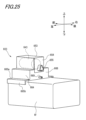
- FIG. FIG. 24 is a perspective view showing the front SC 603 attached to the front LiDAR 6f.
- the front LiDAR 6f to which the front SC 603 is attached has a box shape as a whole, and a rectangular front lens portion 120, which is the surface to be cleaned, is provided at the center of the front surface. .
- the front SC 603 is attached to the upper central part of the front LiDAR 6f.
- the front SC 603 has a nozzle 633, a motor 643 that rotates the nozzle 633, a motor housing 653 that houses the motor 643, and a mounting portion 663 that mounts the motor housing 653 to the front LiDAR 6f.
- the nozzle 633 is provided to extend vertically from the front side of the motor housing 653 toward the front lens portion 120 of the front LiDAR 6f.
- the nozzle 633 is formed, for example, as a vertically long bar.
- the nozzle 633 is provided with an injection port 634 that injects high-pressure air toward the front lens portion 120 and a first conduit 635 that supplies the high-pressure air to the injection port 634 .
- the injection port 634 is provided on the lower surface of the nozzle 633 so as to face the front lens portion 120 .
- the direction of the jet port 634 is adjusted so that the high-pressure air jetted from the jet port 634 is jetted downward from above the front lens portion 120 .
- the first conduit 635 is provided so as to protrude from the rear surface of the nozzle 633 so as to extend rearward.
- the motor 643 is connected to the nozzle 633.
- the motor 643 is configured to rotate the nozzle 633 to change the position of the injection port 634 of the nozzle 633 with respect to the front lens portion 120 .
- the motor 643 is electrically connected to the cleaner control section 113 . The operation of the motor 643 is controlled by the cleaner control section 113 .
- the motor housing 653 is formed in a box shape that can accommodate the motor 643 .
- the motor housing 653 accommodates the motor 643 therein and is arranged in the upper central portion of the front LiDAR 6f.
- the mounting portion 663 has a housing connecting portion 664 that connects with the motor housing 653 and a sensor connecting portion 665 that connects with the front LiDAR 6f.
- the housing connecting portion 664 is connected to the left side wall and the right side wall of the motor housing 653, and is provided so as to hold the motor housing 653 from both left and right sides.
- An internal space 666 is formed inside the housing connecting portion 664 .
- An opening 667 that communicates with the internal space 666 is formed in the front wall of the housing connecting portion 664 .
- the sensor connecting portion 665 has a top surface connecting portion 665a that abuts on the top surface of the front LiDAR 6f, and a pair of side surface connecting portions 665b that respectively abut on the left and right side surfaces of the front LiDAR 6f.
- the pair of side connecting portions 665b are made of, for example, an elastic member, and fix the front SC 603 to the front LiDAR 6f by elastically gripping the side surfaces of the front LiDAR 6f from both left and right sides.
- the mounting portion 663 is formed integrally with the motor housing 653 in the example shown in FIG.
- FIG. 25 is a perspective view of the front SC 603 shown in FIG. 24 as seen from the rear side.
- a lid portion 654 is provided on the rear side of the motor housing 653 to close the rear opening of the motor housing 653 .
- the lid portion 654 is provided with a wire passage opening 655 through which a wire for supplying electric power to the motor 643 accommodated therein is passed.
- a second pipe line 669 is provided in the housing connecting portion 664 so as to protrude from the rear wall 668 to the outside.
- the second pipe line 669 is also provided to protrude into the internal space 666 of the housing connecting portion 664 through the rear wall 668 .
- the first pipe line 635 of the nozzle 633 described above is connected to the second pipe line 669 projecting into the internal space 666 .
- An external pipeline (not shown) is connected to the second pipeline 669 protruding to the outside, and high-pressure air is supplied from the air pump 115 to the second pipeline 669 via the external pipeline.
- FIG. 26 is a partial cross-sectional view along line AA in FIG.
- a motor 643 is housed inside the motor housing 653 .
- the motor 643 is accommodated with the output shaft 644 protruding from the front wall 656 of the motor housing 653 to the outside.
- an output shaft 644 protruding outside is directly connected to the nozzle 633 .
- the output shaft 644 of the motor 643 is connected to the nozzle 633 by directly fitting into a fitting hole 636 formed on the back side of the nozzle 633 .
- a fitting hole 636 is formed on the back side of the upper end of the nozzle 633 .
- the output shaft 644 of the motor 643 is thereby connected to the upper end of the nozzle 633 .
- the nozzle 633 is configured to rotate about an output shaft 644 as a rotating shaft of the motor 643 as the motor 643 rotates. That is, the nozzle 633 is configured to be directly rotated by the motor 643 by being connected to the output shaft 644 of the motor 643 .
- the front portion of the second pipe line 669 provided through the rear wall 668 of the housing connecting portion 664 is arranged inside the internal space 666 of the housing connecting portion 664 .
- the first pipeline 635 and the second pipeline 669 arranged in the internal space 666 are connected by a flexible pipeline 670 that allows the two pipelines 635 and 669 to communicate with each other.
- the high-pressure air sent from the air pump 115 to the second conduit 669 passes through the first conduit 635 via the flexible conduit 670 and is supplied to the injection port 634 .
- the flexible pipeline 670 is formed of a flexible pipeline, and even if the nozzle 633 rotates as the motor 643 rotates, the first pipeline 635, the second pipeline 669, and the The flexible conduit 670 is configured to bend in conjunction with the movement of the nozzle 633 without generating a large load on the flexible conduit 670 itself.
- the flexible pipeline 670 is formed of a flexible pipeline having a bellows structure.
- the flexible pipeline 670 may be a pipeline that is entirely flexible, or may be a pipeline that is at least partially flexible.
- FIG. 27 is a diagram for explaining the operation of the nozzle 633 of the front SC603.
- the rotational driving force of the motor 643 is directly transmitted to the nozzle 633 . That is, in this example, the rotational axis direction of the output shaft 644 of the motor 643 matches the rotational axis direction of the nozzle 633 .
- the nozzle 633 rotates about the output shaft 644 as the motor 643 rotates, for example, by a movable angle ⁇ .
- the nozzle 633 By switching the rotation of the motor 643 between normal rotation and reverse rotation, the nozzle 633 repeatedly reciprocates in the horizontal direction within the range of the movable angle ⁇ about the output shaft 644 .
- the flexible conduit 670 connected to the first conduit 635 of the nozzle 633 moves in the inner space 666 of the housing connecting portion 664 while bending so as to follow the nozzle 633 .
- the movable angle ⁇ of the nozzle 633 is set to an angle such that the high-pressure air jetted from the jet port 634 is jetted from the left end region to the right end region of the front lens portion 120 .
- the front SC 603 (an example of a cleaner) of the present embodiment injects high-pressure air (an example of a cleaning medium) to the front lens portion 120, which is the surface to be cleaned of the front LiDAR 6f (an example of a sensor).
- a nozzle 633 having an injection port 634 and a motor 643 capable of rotating the nozzle 633 to change the position of the injection port 634 with respect to the front lens portion 120 are provided.
- the motor 643 and the nozzle 633 are directly connected. According to this configuration, since the nozzle 633 is directly connected to the motor 643, the nozzle 633 can be rotated within a predetermined movable range with a small number of parts. As a result, the front lens portion 120 can be efficiently cleaned over a wide range using the compact front SC 603 .
- the motor 643 has its output shaft 644 directly connected to the nozzle 633 .
- the rotating mechanism for the nozzle 633 can be configured with a smaller number of parts.
- the axial direction of the output shaft 644 of the motor 643 matches the rotation axis direction of the nozzle 633 . According to this configuration, the rotation of the motor 643 can be directly transmitted to the nozzle 633 to rotate the nozzle 633 . Thereby, rotation of the nozzle 633 can be realized with a simple configuration.
- the front SC 603 further has a motor housing 653 that accommodates the motor 643 therein, and a mounting portion 663 for mounting the motor housing 653 to the front LiDAR 6f.
- the front SC 603 by directly mounting the front SC 603 having the motor 643 and the nozzle 633 on the front LiDAR 6f, the size of the sensor system 100 as a whole can be reduced.
- the nozzle 633 has a first conduit 635 that supplies high-pressure air toward the injection port 634 .
- the mounting portion 663 is provided with a second pipeline 669 that is connected to the first pipeline 635 of the nozzle 633 to supply high-pressure air to the first pipeline 635 .
- a flexible conduit 670 is provided between the first conduit 635 and the second conduit 669 . According to this configuration, the flexible conduit 670 provided between the first conduit 635 and the second conduit 669 bends in response to the rotation of the nozzle 633, thereby rotating the nozzle 633. Even in this case, high-pressure air can be appropriately supplied from each conduit toward the injection port 634 .
- the front LiDAR 6f is an in-vehicle sensor mounted on the vehicle 1. According to this configuration, the front lens portion 120 of the in-vehicle sensor can be efficiently cleaned over a wide area by the small front SC 603 .
- the flexible pipeline 670 is provided between the first pipeline 635 and the second pipeline 669 as the pipeline for supplying high-pressure air.
- the first pipeline 635 and the second pipeline 669 may be configured as a flexible pipeline.
- the flexible conduit 670 may be formed integrally with the first conduit 635 as a part of the first conduit 635 . That is, the first pipeline 635 may be formed as a pipeline having a part thereof having flexibility. The rear end side of the first pipeline 635 may be connected to the front end side of the second pipeline 669 .
- the flexible conduit 670 may be formed integrally with the second conduit 669 as a part of the second conduit 669 . That is, the second pipeline 669 may be formed as a pipeline having flexibility in part. The front end side of the second pipeline 669 may be connected to the rear end side of the first pipeline 635 .
- At least one of the first pipeline 635 and the second pipeline 669 may be provided with a flexible portion.
- the flexible region bends in accordance with the rotation of the nozzle 633, so that even when the nozzle 633 rotates, high-pressure air can be appropriately supplied from the duct toward the injection port 634. can.
- the motor housing 653 and the mounting portion 663 are integrally formed, but the present invention is not limited to this.
- the motor housing 653 and the attachment portion 663 may be formed separately, and the motor housing 653 may be attached to the attachment portion 663 .
- front WW 101, rear WW 102, right HC 107 and left HC 108 inject cleaning liquid
- front SC 103 (103A-103D), 503, 603, rear SC 104, right SC 105 and left SC 106 inject high pressure air.
- front SC 103 103A-103D
- 503, 603, rear SC 104, right SC 105 and left SC 106 inject high pressure air.
- the vehicle control unit 3, the cleaner control unit 113, and the sensor control unit 114 are provided as separate components, but this is not the only option.
- the vehicle control unit 3 and the sensor control unit 114 may be configured integrally, the vehicle control unit 3 and the cleaner control unit 113 may be configured integrally, or the vehicle control unit 3 and the cleaner control unit 113 may be configured integrally.
- 113 and sensor control unit 114 may be configured integrally.
- the sensor system 100 is installed in a vehicle that can operate automatically has been described, but the sensor system 100 may be installed in a vehicle that cannot operate automatically.
- the cleaner that cleans the in-vehicle sensor mounted on the vehicle 1 has been described, but the present invention is not limited to this.
- the cleaner of this sensor system may be used, for example, as a cleaner for cleaning surveillance cameras, LiDAR, etc., which are provided in infrastructure such as roads and railways.
- the surface to be cleaned can be efficiently cleaned over a wide area with a compact cleaner.
Landscapes
- Engineering & Computer Science (AREA)
- Mechanical Engineering (AREA)
- Electric Suction Cleaners (AREA)
Priority Applications (1)
| Application Number | Priority Date | Filing Date | Title |
|---|---|---|---|
| JP2023556420A JPWO2023074614A1 (https=) | 2021-11-01 | 2022-10-24 |
Applications Claiming Priority (6)
| Application Number | Priority Date | Filing Date | Title |
|---|---|---|---|
| JP2021178592 | 2021-11-01 | ||
| JP2021-178592 | 2021-11-01 | ||
| JP2021187224 | 2021-11-17 | ||
| JP2021-187223 | 2021-11-17 | ||
| JP2021-187224 | 2021-11-17 | ||
| JP2021187223 | 2021-11-17 |
Publications (1)
| Publication Number | Publication Date |
|---|---|
| WO2023074614A1 true WO2023074614A1 (ja) | 2023-05-04 |
Family
ID=86157795
Family Applications (1)
| Application Number | Title | Priority Date | Filing Date |
|---|---|---|---|
| PCT/JP2022/039501 Ceased WO2023074614A1 (ja) | 2021-11-01 | 2022-10-24 | クリーナ |
Country Status (2)
| Country | Link |
|---|---|
| JP (1) | JPWO2023074614A1 (https=) |
| WO (1) | WO2023074614A1 (https=) |
Citations (6)
| Publication number | Priority date | Publication date | Assignee | Title |
|---|---|---|---|---|
| US20030066907A1 (en) * | 2001-10-05 | 2003-04-10 | Drouillard Jerome R. | Windshield washer system for automotive vehicle |
| JP2007253731A (ja) * | 2006-03-22 | 2007-10-04 | Toyota Motor Corp | 構造物用空調装置 |
| JP2018053877A (ja) * | 2016-09-30 | 2018-04-05 | アスモ株式会社 | 電動エアポンプ及び車載光学センサ洗浄装置 |
| JP2019034712A (ja) * | 2017-08-15 | 2019-03-07 | 株式会社デンソー | 車載センサ洗浄装置 |
| JP2021011150A (ja) * | 2019-07-04 | 2021-02-04 | クラリオン株式会社 | 洗浄装置 |
| JP2021014172A (ja) * | 2019-07-11 | 2021-02-12 | 株式会社デンソー | 車載センサ洗浄装置 |
-
2022
- 2022-10-24 WO PCT/JP2022/039501 patent/WO2023074614A1/ja not_active Ceased
- 2022-10-24 JP JP2023556420A patent/JPWO2023074614A1/ja active Pending
Patent Citations (6)
| Publication number | Priority date | Publication date | Assignee | Title |
|---|---|---|---|---|
| US20030066907A1 (en) * | 2001-10-05 | 2003-04-10 | Drouillard Jerome R. | Windshield washer system for automotive vehicle |
| JP2007253731A (ja) * | 2006-03-22 | 2007-10-04 | Toyota Motor Corp | 構造物用空調装置 |
| JP2018053877A (ja) * | 2016-09-30 | 2018-04-05 | アスモ株式会社 | 電動エアポンプ及び車載光学センサ洗浄装置 |
| JP2019034712A (ja) * | 2017-08-15 | 2019-03-07 | 株式会社デンソー | 車載センサ洗浄装置 |
| JP2021011150A (ja) * | 2019-07-04 | 2021-02-04 | クラリオン株式会社 | 洗浄装置 |
| JP2021014172A (ja) * | 2019-07-11 | 2021-02-12 | 株式会社デンソー | 車載センサ洗浄装置 |
Also Published As
| Publication number | Publication date |
|---|---|
| JPWO2023074614A1 (https=) | 2023-05-04 |
Similar Documents
| Publication | Publication Date | Title |
|---|---|---|
| JP7165659B2 (ja) | 車両用クリーナシステムおよび車両用クリーナ制御装置 | |
| JP7486525B2 (ja) | センサユニット | |
| JP7438173B2 (ja) | 車両用クリーナシステムおよび車両用クリーナシステムを備える車両 | |
| JP7663646B2 (ja) | 車両用クリーナシステムおよび車両用クリーナシステムを備える車両 | |
| WO2021079911A1 (ja) | センサシステム及びセンサユニット | |
| JP7362592B2 (ja) | 車両用クリーナシステム、車両システム、車両用クリーナシステムによる洗浄方法、車両用クリーナ制御装置 | |
| EP3988837B1 (en) | Vehicular air curtain system | |
| JPWO2018043743A1 (ja) | クリーナ、クリーナ付きセンサおよび当該クリーナまたは当該クリーナ付きセンサを備える車両 | |
| US20200189528A1 (en) | Vehicle cleaner system | |
| US20210094474A1 (en) | Sensor module for a vehicle including at least one sensor | |
| JPWO2019059083A1 (ja) | 車両用センサシステム、当該車両用センサシステムを備えた車両、および車両 | |
| CN111867898A (zh) | 车辆用清洁系统及车辆用系统 | |
| CN113574411A (zh) | 用于检测传感器外壳上的障碍物的方法和系统 | |
| JP2020094624A (ja) | 流路切替ボックスおよび車両用クリーナシステム | |
| JP7443261B2 (ja) | 車両用クリーナシステム | |
| JP7125849B2 (ja) | 車両システム | |
| CN117584892A (zh) | 提供空气和液体清洁流的车辆传感器清洁装置和车辆传感器系统 | |
| JP2017128188A (ja) | 付着物除去装置 | |
| JP7515011B2 (ja) | カメラ、aピラー構成、及び車両 | |
| WO2023074614A1 (ja) | クリーナ | |
| CN215110838U (zh) | 电磁阀以及具备电磁阀的车辆用清洁器系统 | |
| WO2019172364A1 (ja) | 車両用のクリーナ付きセンサシステム | |
| JP7156042B2 (ja) | 車両用清掃装置 | |
| WO2023048129A1 (ja) | センサシステム及びクリーナ | |
| WO2019044466A1 (ja) | 車両用クリーナユニットおよびカメラ付きサイドターンシグナルランプ |
Legal Events
| Date | Code | Title | Description |
|---|---|---|---|
| 121 | Ep: the epo has been informed by wipo that ep was designated in this application |
Ref document number: 22886941 Country of ref document: EP Kind code of ref document: A1 |
|
| WWE | Wipo information: entry into national phase |
Ref document number: 2023556420 Country of ref document: JP |
|
| NENP | Non-entry into the national phase |
Ref country code: DE |
|
| 122 | Ep: pct application non-entry in european phase |
Ref document number: 22886941 Country of ref document: EP Kind code of ref document: A1 |