WO2023074209A1 - 把持力推定装置、把持力推定方法及び把持力推定プログラム - Google Patents
把持力推定装置、把持力推定方法及び把持力推定プログラム Download PDFInfo
- Publication number
- WO2023074209A1 WO2023074209A1 PCT/JP2022/035386 JP2022035386W WO2023074209A1 WO 2023074209 A1 WO2023074209 A1 WO 2023074209A1 JP 2022035386 W JP2022035386 W JP 2022035386W WO 2023074209 A1 WO2023074209 A1 WO 2023074209A1
- Authority
- WO
- WIPO (PCT)
- Prior art keywords
- gripping force
- trace
- gripping
- model
- gripped
- Prior art date
- Legal status (The legal status is an assumption and is not a legal conclusion. Google has not performed a legal analysis and makes no representation as to the accuracy of the status listed.)
- Ceased
Links
Images








Classifications
-
- B—PERFORMING OPERATIONS; TRANSPORTING
- B25—HAND TOOLS; PORTABLE POWER-DRIVEN TOOLS; MANIPULATORS
- B25J—MANIPULATORS; CHAMBERS PROVIDED WITH MANIPULATION DEVICES
- B25J13/00—Controls for manipulators
- B25J13/08—Controls for manipulators by means of sensing devices, e.g. viewing or touching devices
-
- B—PERFORMING OPERATIONS; TRANSPORTING
- B25—HAND TOOLS; PORTABLE POWER-DRIVEN TOOLS; MANIPULATORS
- B25J—MANIPULATORS; CHAMBERS PROVIDED WITH MANIPULATION DEVICES
- B25J19/00—Accessories fitted to manipulators, e.g. for monitoring, for viewing; Safety devices combined with or specially adapted for use in connection with manipulators
- B25J19/02—Sensing devices
- B25J19/04—Viewing devices
-
- G—PHYSICS
- G05—CONTROLLING; REGULATING
- G05B—CONTROL OR REGULATING SYSTEMS IN GENERAL; FUNCTIONAL ELEMENTS OF SUCH SYSTEMS; MONITORING OR TESTING ARRANGEMENTS FOR SUCH SYSTEMS OR ELEMENTS
- G05B19/00—Program-control systems
- G05B19/02—Program-control systems electric
- G05B19/18—Numerical control [NC], i.e. automatically operating machines, in particular machine tools, e.g. in a manufacturing environment, so as to execute positioning, movement or co-ordinated operations by means of program data in numerical form
- G05B19/4155—Numerical control [NC], i.e. automatically operating machines, in particular machine tools, e.g. in a manufacturing environment, so as to execute positioning, movement or co-ordinated operations by means of program data in numerical form characterised by program execution, i.e. part program or machine function execution, e.g. selection of a program
Definitions
- the present disclosure relates to a gripping force estimation device, a gripping force estimation method, and a gripping force estimation program. More specifically, it relates to information processing for estimating an appropriate grasping force when a robot arm grasps an object.
- robots Mechanical devices such as robot arms (hereinafter collectively referred to as "robots") have been introduced in various technical fields and play an important role in the process.
- robot control One of the most important items in robot control is the process of determining an appropriate gripping force when the robot grips an object.
- a gripping force control device that inputs a motor driving current and a motor rotation speed, estimates the gripping force of the gripping device, and performs control so as to eliminate the deviation between the gripping force estimated value and the gripping force target value. It has been proposed (for example, Patent Document 1). Also, there is known a technique of obtaining tactile information, such as how much force should be applied to grip an object, from visual information of the object using machine learning (for example, Patent Document 2).
- Robots can learn the relationship between objects and appropriate gripping force autonomously, in order to save the trouble of repeating trials and investigating the appropriate gripping force for various objects when the robot is to grip various objects. It is desirable to use a method that For example, by attaching a tactile sensor to the tip of the gripper of the robot arm, we have the robot grip various objects. Learn relationships. With this method, once an autonomous learning system is constructed, it is possible to achieve gripping with an appropriate gripping force without human intervention.
- the tactile sensor is fragile, repeated trials for learning may change the measured value or cause it to malfunction. Also, since the tactile sensor is relatively expensive, it is desirable to use it as infrequently as possible. A method of attaching a tactile sensor to a human hand or finger and teaching the grip force measured by the robot arm is also conceivable. There is also a risk that a person may not be able to grip the object with an appropriate grip force because of the difference in the sensation of the fingertips.
- a gripping force estimating device a gripping force estimating method, and a gripping force that can teach a robot a measured gripping force without changing the sense of a person's hand while reducing the frequency of use of a tactile sensor.
- a gripping force estimation device calculates a gripping force when a person grips an object, and traces of the person's grip that are attached to the object when gripping the object.
- the predetermined a gripping force estimating device comprising: a generation unit that generates a model that outputs a gripping force when an object is gripped.
- 10 is a flowchart showing the flow of gripping processing of a robot to which the technology of the present disclosure can be applied; It is a figure which shows an example of a structure of the grip force estimation system which concerns on embodiment.
- 6 is a flow chart showing the flow of learning data set acquisition processing according to the embodiment. It is a figure for demonstrating the learning data set which concerns on embodiment. It is a figure for demonstrating the model which concerns on embodiment.
- 4 is a flowchart showing the flow of model learning processing according to the embodiment. 4 is a flowchart showing the flow of teaching processing according to the embodiment; It is a figure for demonstrating the teaching data which concerns on embodiment.
- FIG. 7 is a flowchart showing the flow of gripping force determination processing according to the embodiment; It is a figure which shows the structural example of the information processing apparatus which concerns on embodiment. It is a figure which shows an example of the learning data storage part which concerns on embodiment of this indication. It is a figure which shows an example of the teaching data storage part which concerns on embodiment of this indication.
- FIG. 10 is a diagram showing a configuration example of a model for executing a fingerprint trace complementing process
- FIG. 11 is a flow chart showing the flow of learning processing of an complementor for fingerprint traces
- FIG. FIG. 4 is a diagram showing a configuration example of a model that executes extraction processing of surface characteristics of an object
- FIG. 4 is a diagram for explaining an extended learning data set for learning a surface feature extractor;
- FIG. 10 is a diagram showing a configuration example of a model for executing a fingerprint trace complementing process
- FIG. 11 is a flow chart showing the flow of learning processing of an complementor for fingerprint traces
- FIG. 4
- FIG. 4 is a diagram for explaining a pre-learning data set;
- FIG. 4 is a flow chart showing the flow of learning processing of a surface characteristic extractor;
- 10 is a flow chart showing the flow of teaching processing in consideration of verbal instructions.
- 1 is a hardware configuration diagram showing an example of a computer that implements functions of an information processing apparatus;
- FIG. 4 is a flow chart showing the flow of learning processing of a surface characteristic extractor;
- 10 is a flow chart showing the flow of teaching processing in consideration of verbal instructions.
- Embodiment 1-1 Application example of technology according to present disclosure 1-2. Configuration of gripping force estimation system according to embodiment 1-3. Details of grip force estimation process according to embodiment 1-4. Configuration of Information Processing Apparatus According to Embodiment 1-5. Application example of embodiment 1-5-1. Fingerprint Trace Complementary Processing 1-5-2. Processing Considering Object Surface Characteristics 1-5-3. Processing Considering Unique Expression by User 1-6. Modified example of embodiment 2. Other embodiments 3. Effects of the gripping force estimation device according to the present disclosure4. Hardware configuration
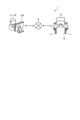
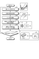
- FIG. 1 is a flowchart showing the flow of gripping processing of a robot 10 to which the technique of the present disclosure can be applied.
- the robot 10 has a so-called parallel two-fingered gripper with two gripping points.
- the robot 10 grips the object 20 with a gripper, lifts the object 20, and moves the object 20 to an arbitrary location. The flow of such processing will be described with reference to FIG.
- an administrator or the like who uses the robot 10 determines a gripping position and orientation for the robot 10 to grip the object 20 (step S11).
- the user inputs the determined grip position/orientation to the robot 10 (step S12).
- the robot 10 brings the gripper closer to the object 20 after adjusting the position and orientation for gripping the object 20 .
- the user determines the grasping force for the robot 10 to grasp the object 20 (step S13).
- the user inputs the determined grip force to the robot 10 (step S14).
- the robot 10 can grip the object 20 without damaging the object 20 by gripping the object 20 with gripping force input by the user.
- the robot 10 moves the gripped object 20 to an arbitrary location according to the user's instruction (step S15). It is assumed that the robot 10 to which the technology of the present disclosure can be applied performs gripping processing as shown in FIG.
- a tactile sensor attached to the tip of the gripper is used to measure the gripping force with which the gripper is closed, and the value is calculated.
- the user is required to determine an appropriate grasping force for each object to be grasped. That is, if the robot arm always grips with the maximum output gripping force, depending on the gripped object, the shape may be deformed or broken.
- the robot arm grips the object with a gripping force lower than the appropriate value, the gripped object cannot be completely gripped and may be dropped.
- the simplest method to achieve gripping with an appropriate gripping force is to have the robot arm grip the target object with various gripping forces and determine the appropriate value through trial and error.
- this method requires an enormous amount of time and effort.
- the user has to repeat this trial and error every time a new object is given, and the generalizability is also low.
- a method in which the robot arm autonomously learns the relationship between the object and the appropriate gripping force is conceivable.
- an autonomous learning system is constructed, and once it is activated, it is possible to achieve gripping with an appropriate gripping force without user intervention.
- the technique according to the present disclosure solves the above problem by the processing described below. That is, the technology according to the present disclosure acquires a gripping force when a person grips an object and traces of the person's grip attached to the object when gripping, and creates learning data that combines the acquired gripping force and the traces. Based on this, when an image containing traces when a person grips a predetermined object is input, a model is generated that outputs the gripping force when the predetermined object is gripped.
- the technology according to the present disclosure grips an object with an inked finger and generates a grip force estimator that has learned the relationship between the grip force and ink traces. Then, when a person teaches the robot 10 about the gripping force, the person grips the object with ink applied to the finger, and the degree of gripping force with which the person grips the object is determined from the image of the ink marks on the object. to estimate whether In this way, by using ink, there is no need to attach a device such as a tactile sensor. . When learning the relationship between ink trace images and grip strength, a person applies ink to a finger and grips an object with a tactile sensor attached with various grip strengths to create a learning data set.
- the subsequent grip force estimation process can be taught by applying ink without the need for a person to install the device.
- An appropriate gripping force can be calculated at a higher speed than the method of erroneously estimating the gripping force.
- the technology according to the present disclosure is used to determine the gripping force when the robot 10 grips the object 20 in the example shown in FIG.
- the robot 10 is a domestic robot
- the user can use the technology according to the present disclosure to teach the domestic robot a grasping force.
- the technique according to the present disclosure consists of a simple process in which a user grips an object with ink on it and photographs the traces of the object, and it is possible for the user to easily teach grip strength.
- FIG. 2 is a diagram showing an example of the configuration of the gripping force estimation system 1 according to the embodiment. Information processing according to the embodiment of the present disclosure is implemented by the grip force estimation system 1 shown in FIG. 2 .
- the gripping force estimation system 1 includes an information processing device 100 and a robot 10 .
- the information processing device 100 and the robot 10 are connected to a network N (the Internet, short-range wireless communication, etc.) by wire or wirelessly, and transmit and receive information via the network N.
- a network N the Internet, short-range wireless communication, etc.
- the information processing device 100 is an example of a grip force estimation device according to the present disclosure, and executes information processing according to the present disclosure.
- the information processing apparatus 100 generates a learned model (hereinafter simply referred to as “model”) that has learned the relationship between the ink trace and the gripping force, and the robot 10 uses the generated model to grip the target object.
- model a learned model
- the information processing apparatus 100 is, for example, a computer, server, tablet terminal, or the like that can receive input from a user.
- the robot 10 is an example of a mechanical device that cooperates with the information processing device 100 to perform predetermined processing.
- the robot 10 performs a process of gripping an object and moving the gripped object to a predetermined position as predetermined processing.
- the robot 10 comprises two grippers 11 for gripping objects.
- the robot 10 is provided with a tactile sensor 12 inside the gripper 11 (on the side that grips the object) if necessary.
- the robot 10 includes various general sensors (object detection, image recognition, distance measurement to an object, equilibrium, acceleration, etc.) used to grasp an object. sensor) may be provided.
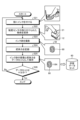
- FIG. 3 is a flowchart showing the flow of learning data set acquisition processing according to the embodiment.
- the user applies ink to the finger that grips the object (step S21). Subsequently, the user grips the object 21 to which the tactile sensor 12 is attached (step S22).
- the tactile sensor 12 is attached to the object 21 on the back side of the object, that is, on the side that is not directly touched by the user's finger.
- the user photographs the ink trace 80 (step S23). That is, the information processing apparatus 100 acquires the image 50 including the ink traces 80 .
- the information processing apparatus 100 records the gripping force observed when the ink trace 80 adheres (step S24).
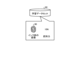
- the information processing apparatus 100 saves the image 57 including the ink traces 80 and the grip force (10 N (Newton) in the example of FIG. 3) as a data set as a learning data set 60 .
- the learning data in FIG. 3 is data obtained by combining the gripping force when the user grips the object 21 and the ink marks 80, which are traces caused by the user's grip and attached to the object 21 during gripping.
- the information processing device 100 determines whether or not the data set used for learning is sufficient (step S26).
- the user may arbitrarily determine whether the data set is sufficient or not according to the type of model to be learned, the accuracy of grasping force estimation desired by the user, and the like. If the data set is not sufficient (step S26; No), the user changes the object 21 to another object and repeats the flow from step S21 to step S25 any number of times.
- step S26 If the data set is sufficient (step S26; Yes), the information processing device 100 terminates the learning data set acquisition process.
- FIG. 4A is a diagram for explaining a learning data set according to the embodiment
- the learning data set saved as the learning data set 60 is an image containing ink marks 80 when an object is gripped and the gripping force observed in that gripping.
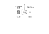
- FIG. 4B is a diagram for explaining the model according to the embodiment.
- a model 70 according to an embodiment takes an image of an ink trace as an input and outputs a predicted grip force corresponding to the image.
- the model 70 has a configuration as, for example, a CNN (Convolutional Neural Network). Note that the model 70 is not limited to the CNN, and may have any configuration as long as it can input an image and output a gripping force corresponding to the image.
- the ink densities and the sharpness of fingerprints are different between traces when the user grips an object with a relatively large grip force and traces when the user grips an object with a relatively small grip force.
- the model 70 treats such differences in traces as feature quantities, and learns the relationship between the traces and the grasping force when the traces are obtained.
- the learned model 70 can output the predicted gripping force when the trace is obtained when the trace is input. That is, according to the model 70 , the user can recognize the gripping force when gripping the object without using the tactile sensor 12 .
- FIG. 5 is a flowchart showing the flow of learning processing for the model 70 according to the embodiment.
- the information processing apparatus 100 extracts pairs of ink trace images and gripping forces from the learning data set 60 acquired in the process of FIG. 3 (step S31). Subsequently, the information processing apparatus 100 inputs the ink trace image to the CNN that configures the model 70 (step S32).
- the information processing device 100 calculates the error between the gripping force predicted by the model 70 (the gripping force output from the model 70) and the actual gripping force (step S33).
- the model 70 outputs "9N” as the predicted gripping force, but the actual gripping force associated with the ink trace is "10N”.
- the information processing apparatus 100 updates the parameters of the CNN so that the error is minimized (step S34).
- the information processing device 100 determines whether or not the loss error is sufficiently small (step S35).
- the criterion for determining whether the loss error is sufficiently small may be arbitrarily determined by the user by applying it to the accuracy of the model 70 desired by the user, arbitrary CNN evaluation criteria, or the like.
- the processing from step S31 to step S34 is repeated to continue learning.
- the information processing apparatus 100 completes generation of the model 70 capable of grasping force estimation, and acquires the model 70.
- the information processing apparatus 100 is a method used for learning an NN (Neural Network), and is a method that can be learned according to the purpose of the model 70. Any other method, if any, may be employed.
- NN Neuronal Network
- the information processing device 100 has generated the model 70, which is a model for estimating the gripping force of the object. 6 and subsequent figures, a process of estimating the gripping force of an unknown object by the information processing apparatus 100 using the model 70 and generating teaching data will be described.
- the user performs the processing shown in FIG. 6 and after in order to teach the robot 10 the grasping force of an unknown object.
- the teaching step the user prepares an object for teaching the gripping force to the robot 10 and ink.
- the teaching step does not require the tactile sensor 12 .
- the outline of the teaching step is that the user puts ink on his/her finger, grips the object whose gripping force is to be taught, and saves the gripping force and object information estimated from the fingerprint in the database.
- the user can create a database in which object information and grip force are associated without using the tactile sensor 12 by repeating this flow as many times as the number of objects to be taught. Such processing will be described along the flow with reference to FIG. FIG. 6 is a flowchart showing the flow of teaching processing according to the embodiment.
- the user inks the finger used for gripping (step S41). Then, the user grips an arbitrary object 22 to be gripped (step S42).
- the user photographs the ink traces 81 adhering to the object 22 (step S43).
- the information processing apparatus 100 acquires an image including the ink traces 81 .
- the information processing device 100 uses the learned predictor (that is, the model 70) to estimate the grip force on the object 22 (step S44). That is, the information processing apparatus 100 inputs an image including the ink traces 81 to the model 70 and causes the predicted grip force corresponding to the ink traces 81 to be output. In the example of FIG. 6, the information processing apparatus 100 estimates that the gripping force when the user grips the object 22 is "2N".
- the information processing apparatus 100 combines the estimated gripping force and the identification information for identifying the gripped object 22, and stores the data in a database (in the example of FIG. 6, the teaching data 61) holding teaching data for the robot 10. Hold.
- the information processing device 100 determines whether or not to end the collection of teaching data (step S46). When continuing the collection of teaching data (step S46; No), the information processing apparatus 100 repeats the processing from step S41 to step S45 to continue collecting teaching data of various objects. On the other hand, when the user determines that the necessary number of pieces of teaching data have been collected, the information processing apparatus 100 ends the collection of teaching data (step S46; Yes).
- FIG. 7 is a diagram for explaining teaching data according to the embodiment.
- the teaching data 61 is a combination of gripping force when the user grips an object (that is, gripping force estimated by the model 70) and identification information for identifying the object gripped by the user. It is.
- Identification information for identifying an object is, for example, linguistic information such as the name of the object. In the example of FIG. 7, the object is given linguistic information (label) "egg". Note that the identification information may be any information as long as it identifies an object, and may be, for example, an image of the object.
- FIG. 8 is a flowchart showing the flow of gripping force determination processing according to the embodiment.
- the information processing device 100 recognizes the object that the robot 10 is trying to grasp (step S51).
- the recognition of the object is performed, for example, by image recognition processing of the result of the information processing apparatus 100 or the robot 10 capturing an image of the object using a camera or the like, or by inputting object information (for example, a name such as "egg") by the user. It may be realized by any method such as
- the information processing apparatus 100 refers to the database in which the teaching data 61 is stored, searches for the gripping force of the object to be gripped, and determines the gripping force of the robot 10 (step S52). Specifically, the information processing apparatus 100 searches the database for the gripping force obtained in collecting the teaching data (in the example of FIG. 8, the gripping force “2N” when the user grips the object “egg”). , and the results are input to the robot 10 to determine the gripping force.
- the information processing apparatus 100 may notify the user to that effect. In this case, the user applies ink to the finger and grips the object to acquire the ink trace. By inputting the image including the ink traces into the model 70, the information processing apparatus 100 can immediately estimate an appropriate gripping force.
- the information processing apparatus 100 acquires the gripping force when the user grips the object and the traces of the user's grip that are attached to the object when gripping. Further, information processing apparatus 100 detects a predetermined object when an image including a trace when the user grips a predetermined object is input based on learning data obtained by combining the acquired gripping force and the trace. A model 70 is generated that outputs a gripping force when gripped. When the robot 10 grips an arbitrary object, the information processing apparatus 100 inputs to the robot 10 the value estimated by the model 70 as the gripping force when the user grips the object. 10 can determine the appropriate gripping force to grip the object of interest.
- the information processing apparatus 100 it is possible to input an appropriate grasping force to the robot 10 without using the tactile sensor 12 or the like.
- the estimation of the gripping force is realized by a simple method in which the user applies ink to grip the object.
- the information processing apparatus 100 reduces the frequency of use of the tactile sensor 12 when inputting the gripping force to the robot, and allows the robot 100 to obtain an appropriate gripping force that has been measured without changing the sense of the human hand. can be taught to
- FIG. 9 is a diagram showing a configuration example of the information processing device 100 according to the embodiment of the present disclosure.
- the information processing device 100 has a communication unit 110, a storage unit 120, and a control unit .
- the information processing apparatus 100 includes an input unit (for example, a keyboard, a mouse, etc.) that receives various operations from a user or the like who manages the information processing apparatus 100, and a display unit (for example, a liquid crystal display, etc.) for displaying various information.
- an input unit for example, a keyboard, a mouse, etc.
- a display unit for example, a liquid crystal display, etc.
- the communication unit 110 is implemented by, for example, a NIC (Network Interface Card), a network interface controller, or the like.
- the communication unit 110 is connected to the network N by wire or wirelessly, and transmits/receives information to/from the robot 10 or the like via the network N.
- Network N is, for example, Bluetooth (registered trademark), the Internet, Wi-Fi (registered trademark), UWB (Ultra Wide Band), LPWA (Low Power Wide Area), ELTRES (registered trademark), or other wireless communication standards or methods. Realized.
- the storage unit 120 is implemented by, for example, a semiconductor memory device such as RAM (Random Access Memory) or flash memory, or a storage device such as a hard disk or optical disk.
- Storage unit 120 has learning data storage unit 121 and teaching data storage unit 122 . Each storage unit will be described below in order.
- the learning data storage unit 121 stores learning data sets used for model generation.
- the learning data storage unit 121 corresponds to, for example, the learning data set 60 shown in FIG.
- the learning data stored in the learning data storage unit 121 may be appropriately obtained from an external server or the like without being held by the information processing apparatus 100 .
- FIG. 10 shows an example of the learning data storage unit 121 according to the embodiment.
- FIG. 10 is a diagram showing an example of the learning data storage unit 121 according to the embodiment of the present disclosure.
- the learning data storage unit 121 has items such as "learning data ID”, "image data”, and "grip force”. 10 and 11, the information held in each item may be indicated by a concept such as "B01", but in reality, specific information described below is stored in each item.
- Training data ID indicates identification information that identifies each learning data.
- Image data indicates an image containing traces attached to an object when the user grips the object.
- Finger indicates the actual gripping force measured by the tactile sensor 12 or the like when the user grips an object.
- the teaching data storage unit 122 associates and stores information about an object to be gripped with a gripping force estimated from a trace when the user grips the object.
- FIG. 11 shows an example of the teaching data storage unit 122 according to the embodiment.
- FIG. 11 is a diagram showing an example of the teaching data storage unit 122 according to the embodiment of the present disclosure.
- the teaching data storage unit 122 has items such as "teaching data ID", "object information”, and "grip force”.
- “Teaching data ID” indicates identification information that identifies teaching data.
- Object information indicates various information for identifying an object.
- the object information is, for example, a label (ID information) that can identify the object, such as the name of the object or an image of the object.
- Predicted Grip Force indicates the grip force predicted by the model 70 based on the footprint.
- the control unit 130 uses a CPU (Central Processing Unit), an MPU (Micro Processing Unit), etc. to transfer a program (for example, a gripping force estimation program according to the present disclosure) stored inside the information processing apparatus 100 to a RAM (Random Access Memory) or the like as a work area.
- a program for example, a gripping force estimation program according to the present disclosure
- the control unit 130 is a controller, and may be realized by an integrated circuit such as an ASIC (Application Specific Integrated Circuit) or an FPGA (Field Programmable Gate Array).
- control unit 130 includes an acquisition unit 131, a generation unit 132, an estimation unit 133, and an input unit 134, and implements or executes the information processing functions and actions described below.
- the internal configuration of the control unit 130 is not limited to the configuration shown in FIG. 9, and may be another configuration as long as it performs information processing to be described later.
- the acquisition unit 131 acquires various types of information. For example, the acquisition unit 131 acquires the gripping force when the user grips the object, and the traces of the user's grip that are attached to the object during gripping.
- the acquisition unit 131 acquires the gripping force measured by the tactile sensor 12 or the like when the user grips the object, and the fingerprint trace of the user due to gripping. That is, the acquisition unit 131 acquires the user's fingerprint trace attached to the object when the user grips the object with a finger or the like that has been inked in advance. More specifically, the acquiring unit 131 acquires an image obtained by photographing the fingerprint of the user, thereby acquiring the fingerprint of the user included in the image.
- the acquisition unit 131 associates the acquired grip force with the user's fingerprint trace and stores them in the storage unit 120 .
- the generating unit 132 Based on the learning data obtained by combining the grip force and the trace acquired by the acquisition unit 131, the generating unit 132 generates the predetermined object when an image including the trace when the user grips the predetermined object is input. A model 70 is generated that outputs the gripping force when the is gripped.
- the generation unit 132 receives the fingerprint as an input and outputs the grip by learning learning data in which the grip force and the fingerprint of the user are combined using a learning model having a structure such as a CNN. Generate a model 70 that
- the estimating unit 133 uses the model 70 generated by the generating unit 132 to estimate (predict) the gripping force when the gripping target object is gripped from the image including the trace when the user grips the gripping target object. )do.
- the estimation unit 133 estimates the gripping force when the object to be gripped is gripped, and the identification information for identifying the object to be gripped and the estimated gripping force (predicted gripping force) for the object to be gripped. are stored in the teaching data storage unit 122 in association with each other.
- the input unit 134 inputs the grasping force estimated by the estimating unit 133 to the robot 10 when the robot 10 attempts to grasp an object to be grasped.
- the information processing apparatus 100 may further execute various processes described below in order to realize more robust gripping force estimation processing.
- the gripping force is estimated using the user's fingerprint traces attached to the object.
- the fingerprint being blurred or partially missing.
- the prediction performance of the NN may deteriorate.
- the information processing apparatus 100 acquires a complete fingerprint of the user in advance and learns such features by a deep learning network, so that only a part of the fingerprint can be used at the time of inference. can be restored. Specifically, the information processing apparatus 100 generates a compensator that complements the fingerprint trace before the model 73 that predicts the grip force. Such processing will be described with reference to FIG. 12 and subsequent figures.
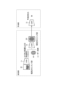
- FIG. 12 is a diagram showing a configuration example of a model that executes complementing processing for fingerprint traces. As shown in FIG. 12, when the fingerprint trace complementing process is executed, a complementer for complementing the fingerprint trace is placed in front of the model 73 (predictor) for estimating the grip force.
- the interpolator has models 71 and 72 having a CNN structure.
- the model 71 takes as input a fingerprint trace 82 which is an actually observed ink trace and is not entirely clear but only a partial trace. Then, when the fingerprint trace 82 is input, the model 71 outputs a feature quantity such as the degree of fading as a vector.
- the model 72 receives the fingerprint 83, which is the complete fingerprint of the user, and the vector representing the feature quantity output from the model 71. Note that the user obtains a clear fingerprint 83 in advance, for example, by photographing the fingerprint using an object (such as paper) on which ink traces are likely to appear.
- the model 72 then outputs a fingerprint generated from these features, that is, a restored fingerprint 84 that is an ink trace whose complete shape has been restored (complemented) from the fingerprint trace 82 .
- the information processing apparatus 100 can predict the gripping force when the fingerprint mark 82 adheres.
- FIG. 13 is a flow chart showing the flow of learning processing of the interpolator for fingerprint traces.
- the information processing apparatus 100 extracts a plurality of pairs of ink trace images and gripping force from a retained data set (for example, information stored in the learning data storage unit 121) (step S61). . Since the grasping force value itself is not used in the learning of the interpolator, illustration in FIG. 13 is omitted. In the example of FIG. 13, the information processing apparatus 100 takes out the learning ink traces 85 and the learning ink traces 86 . It is assumed that this pair is fingerprint traces obtained from the same user.
- the information processing device 100 hides part of one pair of input images and inputs them to the interpolator (step S62).
- the information processing apparatus 100 generates a learning ink trace 87 by hiding a part of the learning ink trace 86, and inputs the generated learning ink trace 87 to the compensator.
- the learning ink trace 87 is input to the model 71 and output as a feature vector indicating features such as fading.
- the feature vector and the training ink trail 85 paired with the training ink trail 86 are then input to the model 72 and output as a predicted ink trail image 88 .
- the information processing apparatus 100 compares the ink trace image 88 predicted by the interpolator with the learning ink trace 86, which is the actual ink trace image, and calculates the error (step S63).
- the information processing device 100 updates the parameters of the interpolator CNN (that is, the model 71 and the model 72) so that the error is minimized (step S64).
- the information processing device 100 determines whether or not the loss error associated with the complementor is sufficiently small (step S65). When the information processing apparatus 100 determines that the loss error is not yet sufficiently small (step S65; No), the processing from step S61 to step S64 is repeated to continue learning. On the other hand, when it is determined that the loss error is sufficiently small (step S65; Yes), the information processing apparatus 100 completes the generation of the model 71 and the model 72 related to the interpolator and acquires the interpolator.
- the information processing apparatus 100 acquires ink traces for learning that are created by performing a process of hiding part of the user's fingerprint traces. Then, the information processing apparatus 100 is a complementary model placed before the grip force prediction model based on learning data obtained by combining the learning ink trace and the original fingerprint trace of the learning ink trace, Generating an interpolation model for reconstructing the original fingerprint from the partially acquired fingerprint.
- the information processing apparatus 100 generates an interpolator placed in front of the predictor, so that even if a fingerprint that is partly missing is obtained in the actual measurement, the information processing apparatus 100 can accurately correspond to the fingerprint.
- the grip force can be estimated.
- the model 71 first extracts features such as the degree of fading as a vector from the partial observation information, and then extracts ink traces from the vector and the image of the fingerprint 83 in perfect condition. It adopts the structure of restoration.
- the configuration of the deep learning network is not limited to this, and other configurations may be adopted.
- the pairs extracted from the learning data set need to be obtained from the same person, but the entire data set need not be created from the same person.
- the information processing apparatus 100 may further execute various processes described below in order to realize more robust gripping force estimation processing.
- the gripping force is estimated using ink traces of the user's fingerprint attached to the object.
- the impression of the ink traces will change even with the same gripping force.
- the processing according to the above embodiment since the input is an image of ink traces, the color characteristics of the surface of the object are taken into account, but it is conceivable that there are many objects of the same color but with different surface characteristics. If the appearance of the ink traces changes even though the gripping force is the same, there is a possibility that the relationship between the image of the ink traces and the gripping force cannot be learned correctly.
- the information processing apparatus 100 can first extract the surface characteristics of the object and predict the gripping force using the extracted characteristics.
- Such a surface feature extractor precedes the predictor, similar to the interpolator described above. Such processing will be described with reference to FIG. 14 and subsequent figures.
- FIG. 14 is a diagram showing a configuration example of a model that executes extraction processing of surface characteristics of an object. As shown in FIG. 14, when executing the process of extracting the surface characteristics of an object, a surface characteristic extractor is placed in front of the model 75 (predictor) that estimates the gripping force.
- the surface feature extractor has a model 74 with a CNN structure.
- the model 74 receives information identifying an object (language information such as the name of the object and an image of the object), and outputs its surface characteristics as feature vectors.
- the information processing apparatus 100 inputs the feature vector obtained from the surface characteristic extractor and the fingerprint trace 89 into the model 75, thereby predicting the gripping force when the fingerprint trace 89 adheres to the object.
- FIGS. 15A and 15B describe learning data used for learning of the surface feature extractor.
- object image information and language information are added.
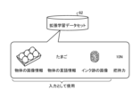
- FIG. 15A is a diagram for explaining an extended learning data set 62 for learning the surface feature extractor.
- the augmented learning data set 62 includes image information of an object, language information of the object, an image of ink traces obtained when the object is gripped, and a gripping force obtained when gripping the object. are associated with.
- the information processing apparatus 100 simultaneously learns the parameters of the surface feature extractor and the predictor using this extended learning data set. In this case, all parameters related to surface feature extractor and predictor parameters are learned end-to-end.
- FIG. 15B is a diagram for explaining the pre-learning data set 63.
- Data used for pre-learning is obtained by associating images of ink traces on an object with various gripping forces and the gripping forces. If possible, such ink trail images should include clean, sharp ink trail images on an object such as paper.
- FIG. 16 is a flow chart showing the flow of learning processing of the surface characteristic extractor.
- the information processing device 100 first extracts a data set used for learning from the augmented learning data set 62 (step S71).
- the information processing apparatus 100 retrieves a data set in which the object "egg", the ink trace 90 when the object is gripped, and the gripping force 10N are associated with each other.
- the information processing apparatus 100 extracts learning data in which a grasping force approximately equal to the gripping force in the learning data extracted in step S71 is associated from the pre-learning data set 63 (step S72).
- the information processing apparatus 100 retrieves a data set in which the ink trace 91 in which the fingerprint is relatively clearly reflected and the gripping force 10N are associated with each other.
- the information processing apparatus 100 inputs the object information (information identifying the object) to the surface property extractor (the model 74 shown in FIG. 16) and predicts the surface property (step S73). Subsequently, the information processing apparatus 100 inputs the extracted surface characteristics and the image of the clean ink trace 91 extracted from the pre-learning data set 63 to the ink trace restorer (model 76). That is, the model 76 predicts the image of the ink trace on the object, and outputs the ink trace 92 as the prediction result (step S74).
- the information processing apparatus 100 calculates the error between the ink trace 92 and the ink trace 90, which is the image of the actual ink trace on the object (step S75).
- the information processing device 100 updates the parameters of the CNN (the model 74 and the model 76 in the example of FIG. 16) related to the surface characteristic extractor so that the error is minimized (step S76).
- the information processing device 100 determines whether the loss error associated with the surface characteristic extractor is sufficiently small (step S77). When the information processing apparatus 100 determines that the loss error is still not sufficiently small (step S77; No), the processing from step S71 to step S76 is repeated to continue learning. On the other hand, if it is determined that the loss error is sufficiently small (step S77; Yes), the information processing apparatus 100 completes the generation of the models 74 and 76 related to the surface characteristic extractor and acquires the surface characteristic extractor.
- the surface feature extractor can identify useful features for transforming clean ink marks 91 into ink marks 90 on real objects, i.e., each object surface properties can be extracted.
- a restorer model 76 exists during the pre-learning shown in FIG. 16, but when using a surface characteristic extractor in the teaching step as shown in FIG. The restorer exists only during pretraining.
- the information processing apparatus 100 acquires identification information for identifying the object and an image of the object, along with the gripping force and trace when the user grips the object. Furthermore, the information processing apparatus 100 uses the trace, the identification information, and the image of the object as learning data, and uses the surface characteristic model, which is a model placed in the preceding stage of the grip force prediction model, for extracting the surface characteristic of the object. Generate an extraction model (surface feature extractor).
- the information processing device 100 can generate a predictor that takes into account features related to surface features.
- the information processing apparatus 100 can predict different gripping forces according to the surface characteristics of the object even for similar fingerprints, and therefore can predict a more suitable gripping force for each object.
- the information processing apparatus 100 learns the relationship between the user's unique instructions and the gripping force as described above, and executes processing for controlling the gripping force of the robot 10 based on the user's unique instructions. good too. This point will be described with reference to FIG. 17 and subsequent drawings.
- FIG. 17 is a flow chart showing the flow of instruction processing in consideration of verbal instructions.
- the user applies ink to the finger (step S81). After that, the user grips an arbitrary object with a verbal instruction arbitrarily set by the user (step S82).
- the user when holding a fragile object such as an egg, the user holds the object together with verbal information such as "gentle”. After that, the user takes an image of ink traces that have adhered when gripping the object (step S83).
- the information processing apparatus 100 uses a pre-generated predictor (for example, the model 70) to estimate the gripping force of the ink trace obtained in step S83 (step S84).
- a pre-generated predictor for example, the model 70
- the information processing apparatus 100 associates the predicted grip force with the language instruction arbitrarily set by the user ("gently" in the example of FIG. 17) and stores them in the database (step S85).
- the information processing apparatus 100 may store the language instruction as text data input by the user, or as voice uttered by the user or data obtained by converting the voice into text.
- the information processing apparatus 100 can generate the teaching data with language 64 in which the object information, the gripping force, and the verbal instruction (instruction such as "gently") for exerting the gripping force are associated with each other. .
- the information processing apparatus 100 determines whether or not to end the collection of teaching data (step S86). When continuing to collect teaching data (step S86; No), the information processing apparatus 100 repeats the processing from step S81 to step S85 to continue collecting teaching data of various objects. On the other hand, when the user determines that the necessary number of pieces of teaching data have been collected, the information processing apparatus 100 ends the collection of teaching data (step S86; Yes).
- the information processing apparatus 100 stores in the storage unit 120 the estimated gripping force for the object to be gripped, the identification information for identifying the object to be gripped, and the user's verbal instruction at the time of gripping in association with each other. do. Further, when the robot 10 attempts to grip an object to be gripped, the information processing apparatus 100 receives a verbal instruction from the user, and inputs to the robot 10 the gripping force stored in the storage unit 120 in association with the verbal instruction. do.
- the information processing device 100 may associate and store the verbal instruction and the tactile information.
- the information processing apparatus 100 teaches the robot 10 using the language-attached teaching data 64, so that when the user gives the robot 10 an instruction such as "hold the egg gently", the robot 10 will be able to grasp the egg. Additionally, the appropriate grip force along the instructions can be determined. Thus, the user can instruct the robot 10 to use a sensuously appropriate grasping force through verbal instructions.
- the information processing apparatus 100 is a computer, a server, or the like.
- the information processing apparatus 100 is not limited to a smartphone, a tablet terminal, or the like, and may be any apparatus as long as it is capable of photographing ink traces and the like and executing learning processing.
- the information processing apparatus 100 may be a digital camera or the like that includes an AI chip capable of executing learning processing.
- traces are not limited to fingerprint traces, as long as they are information that can be used to obtain a relationship with grip strength. and so on.
- the robot 10 is a robot arm having a so-called parallel two-fingered gripper with two gripping points, but the robot 10 is not limited to this and has multiple limbs. It may be a robot arm or the like.
- each component of each device illustrated is functionally conceptual and does not necessarily need to be physically configured as illustrated.
- the specific form of distribution and integration of each device is not limited to the one shown in the figure, and all or part of them can be functionally or physically distributed and integrated in arbitrary units according to various loads and usage conditions. Can be integrated and configured.
- the grip force estimation device (the information processing device 100 in the embodiment) according to the present disclosure includes the acquisition unit (the acquisition unit 131 in the embodiment) and the generation unit (the generation unit 132 in the embodiment).
- the acquisition unit acquires a gripping force when a person grips an object and a trace attached to the object by the person's grip when gripping the object.
- the generation unit grips a predetermined object when an image including a trace when a person grips the predetermined object is input based on learning data obtained by combining the gripping force and the trace acquired by the acquisition unit. Generate a model that outputs the gripping force when
- the gripping force estimating device extends the method of using human teaching to determine the gripping force of a robot, and generates a model that has learned in advance the relationship between the image of the trace (ink trace, etc.) and the gripping force.
- the gripping force estimating device can predict the gripping force from the trace, so the frequency of use of the tactile sensor can be reduced, and the measured gripping force can be taught to the robot without changing the sense of the human hand. be able to.
- the acquisition unit acquires the gripping force when a person grips an object and the fingerprint trace of the person due to gripping.
- the generation unit generates a model based on learning data obtained by combining the grip force and the fingerprint trace.
- the gripping force estimating device can teach the robot an appropriate gripping force by using human fingerprints without the need for special equipment or sensors.
- the acquisition unit acquires a learning fingerprint created by performing processing to hide part of a person's fingerprint.
- the generation unit is a complementary model placed in front of the model, based on training data that combines the learning fingerprint and the original fingerprint of the learning fingerprint, from the partially acquired fingerprint. Generate an imputation model to recover the original fingerprint.
- the grip force estimating apparatus uses fingerprints, which are information that does not change, so that even if a part of the fingerprint is missing, the grip force estimating apparatus can perform more robust processing by complementing and estimating the missing part of the fingerprint. .
- the acquisition unit acquires identification information for identifying the object and an image of the object, along with the grip force and trace when the person grips the object.
- the generating unit uses the trace, the identification information, and the captured image of the object as learning data to generate a surface characteristic extraction model, which is a model placed before the model and extracts the surface characteristic of the object.
- the grip force estimating device can predict an appropriate grip force according to the object by generating a model that takes into account the surface characteristics of the object.
- the gripping force estimating device uses the model generated by the generation unit to estimate the gripping force when the object to be gripped is gripped from the image including the trace when the object to be gripped is gripped by the person. It further includes an estimation unit (estimation unit 133 in the embodiment).
- the grip force estimating device uses the model to estimate the grip force, so it is possible to obtain an appropriate grip force without requiring special equipment or preparation.
- the estimating unit estimates the gripping force when the object to be gripped is gripped, and associates the identification information for identifying the object to be gripped with the estimated gripping force for the object to be gripped, and stores the gripping force. (In the embodiment, the storage unit 120).
- the grip force estimation device can easily teach the robot by storing the teaching data in the storage unit.
- the grip force estimation device further includes an input unit (input unit 134 in the embodiment) that inputs the grip force estimated by the estimation unit to the robot when the robot attempts to grip an object to be gripped.
- an input unit input unit 134 in the embodiment
- the gripping force estimating device inputs the gripping force obtained based on the traces of the person to the robot, and the robot determines the gripping force through trial and error. can be omitted and an appropriate gripping force can be given to the robot.
- the estimation unit associates the estimated gripping force with respect to the object to be gripped, the identification information for identifying the object to be gripped, and the verbal instruction of the user at the time of gripping, and stores them in the storage unit.
- the gripping force estimation device can generate a database that collects teaching data based on verbal instructions by storing gripping force together with verbal instructions such as "Hold gently.”
- the gripping force estimating device includes an input unit that receives a verbal instruction from the user and inputs the gripping force stored in the storage unit in association with the verbal instruction to the robot when the robot attempts to grip an object to be gripped. further provide.
- the person using the robot can teach the robot a perceptually appropriate gripping force through verbal instructions.
- FIG. 18 is a hardware configuration diagram showing an example of a computer 1000 that implements the functions of the information processing apparatus 100.
- the computer 1000 has a CPU 1100 , a RAM 1200 , a ROM (Read Only Memory) 1300 , a HDD (Hard Disk Drive) 1400 , a communication interface 1500 and an input/output interface 1600 .
- Each part of computer 1000 is connected by bus 1050 .
- the CPU 1100 operates based on programs stored in the ROM 1300 or HDD 1400 and controls each section. For example, the CPU 1100 loads programs stored in the ROM 1300 or HDD 1400 into the RAM 1200 and executes processes corresponding to various programs.
- the ROM 1300 stores a boot program such as BIOS (Basic Input Output System) executed by the CPU 1100 when the computer 1000 is started, and programs dependent on the hardware of the computer 1000.
- BIOS Basic Input Output System
- the HDD 1400 is a computer-readable recording medium that non-temporarily records programs executed by the CPU 1100 and data used by such programs.
- the HDD 1400 is a recording medium that records a grip force estimation program according to the present disclosure, which is an example of the program data 1450 .
- a communication interface 1500 is an interface for connecting the computer 1000 to an external network 1550 (for example, the Internet).
- CPU 1100 receives data from another device via communication interface 1500, and transmits data generated by CPU 1100 to another device.
- the input/output interface 1600 is an interface for connecting the input/output device 1650 and the computer 1000 .
- the CPU 1100 receives data from input devices such as a keyboard and mouse via the input/output interface 1600 .
- the CPU 1100 also transmits data to an output device such as a display, speaker, or printer via the input/output interface 1600 .
- the input/output interface 1600 may function as a media interface for reading a program or the like recorded on a predetermined recording medium.
- Media include, for example, optical recording media such as DVD (Digital Versatile Disc) and PD (Phase change rewritable disk), magneto-optical recording media such as MO (Magneto-Optical disk), tape media, magnetic recording media, semiconductor memories, etc. is.
- the CPU 1100 of the computer 1000 implements the functions of the control unit 130 and the like by executing the grip force estimation program loaded on the RAM 1200.
- the HDD 1400 also stores a gripping force estimation program according to the present disclosure and data in the storage unit 120 .
- CPU 1100 reads and executes program data 1450 from HDD 1400 , as another example, these programs may be obtained from another device via external network 1550 .
- the present technology can also take the following configuration.
- an acquisition unit that acquires a gripping force when a person grips an object and traces of the person's grip that are attached to the object when the person grips the object;
- an image containing a trace when a person grips a predetermined object is input based on learning data obtained by combining the gripping force and the trace acquired by the acquisition unit, when the predetermined object is gripped a generator that generates a model that outputs the gripping force of A gripping force estimation device with a
- the acquisition unit Acquiring the gripping force when the person grips the object and the fingerprint trace of the person due to the gripping,
- the generating unit generating the model based on learning data that combines the grip force and the fingerprint trace;
- the gripping force estimation device according to (1).
- the acquisition unit Acquire a learning fingerprint trace created by hiding a part of a person's fingerprint trace
- the generating unit A complementary model placed in front of the model based on learning data combining the learning fingerprint and the original fingerprint of the learning fingerprint, the complementary model being the original from the partially obtained fingerprint. generate an imputation model to reconstruct the fingerprint of The gripping force estimating device according to (2) above.
- the acquisition unit Acquiring identification information for identifying the object and an image of the object, together with the gripping force and the trace when a person grips the object, The generating unit Using the trace, the identification information, and the captured image of the object as learning data, a surface characteristic extraction model, which is a model placed before the model and extracts the surface characteristics of the object, is generated.
- the gripping force estimating device according to any one of (1) to (3) above.
- the grip force estimating device according to any one of (1) to (4).
- the estimation unit estimating a gripping force when the object to be gripped is gripped, and storing identification information for identifying the object to be gripped in association with the estimated gripping force for the object to be gripped in a storage unit; , The gripping force estimating device according to (5) above.
- the grip force estimation device (7) an input unit for inputting the gripping force estimated by the estimation unit to the robot when the robot attempts to grip the object to be gripped;
- the grip force estimation device according to (5) or (6).
- the estimation unit storing in a storage unit the estimated gripping force for the object to be gripped, identification information for identifying the object to be gripped, and a user's verbal instruction at the time of gripping, in association with each other;
- the gripping force estimation device according to any one of (5) to (7).
- an input unit that receives a verbal instruction from the user and inputs the gripping force stored in the storage unit in association with the verbal instruction to the robot when the robot attempts to grip the object to be gripped;
- the gripping force estimation device according to (8).
- a gripping force estimation method comprising: (11) an acquisition unit that acquires a gripping force when a person grips an object and traces attached to the object by the person's grip when the person grips the object; When an image containing a trace when a person grips a predetermined object is input based on learning data obtained by combining the gripping force and the trace acquired by the acquisition unit, when the predetermined object is gripped a generator that generates a model that outputs the gripping force of Grip force estimation program that functions as
- grip force estimation system 10 robot 100 information processing device 110 communication unit 120 storage unit 121 learning data storage unit 122 teaching data storage unit 130 control unit 131 acquisition unit 132 generation unit 133 estimation unit 134 input unit
Landscapes
- Engineering & Computer Science (AREA)
- Human Computer Interaction (AREA)
- Robotics (AREA)
- Mechanical Engineering (AREA)
- Manufacturing & Machinery (AREA)
- Physics & Mathematics (AREA)
- General Physics & Mathematics (AREA)
- Automation & Control Theory (AREA)
- Image Analysis (AREA)
Abstract
Description
1.実施形態
1-1.本開示に係る技術の適用例
1-2.実施形態に係る把持力推定システムの構成
1-3.実施形態に係る把持力推定処理の詳細
1-4.実施形態に係る情報処理装置の構成
1-5.実施形態の応用例
1-5-1.指紋跡の補完処理
1-5-2.物体の表面特性を考慮した処理
1-5-3.ユーザによる独自表現を考慮した処理
1-6.実施形態の変形例
2.その他の実施形態
3.本開示に係る把持力推定装置の効果
4.ハードウェア構成
(1-1.本開示に係る技術の適用例)
図1は、本開示の技術が適用されうるロボット10の把持処理の流れを示すフローチャートである。図1に示す例では、ロボット10は、2か所の把持箇所を備える、いわゆる並行二指グリッパーを有する。ロボット10は、グリッパーで物体20を把持し、物体20を持ち上げ、任意の場所に移動させる処理を行う。かかる処理の流れについて、図1を用いて説明する。
図2は、実施形態に係る把持力推定システム1の構成の一例を示す図である。本開示の実施形態に係る情報処理は、図2に示す把持力推定システム1によって実現される。
次に、図3以下を用いて、実施形態の把持力推定処理の詳細を説明する。図3は、実施形態に係る学習データセットの取得処理の流れを示すフローチャートである。
次に、実施形態に係る情報処理を実行する情報処理装置100の構成について説明する。図9は、本開示の実施形態に係る情報処理装置100の構成例を示す図である。
(1-5-1.指紋跡の補完処理)
実施形態に係る情報処理装置100は、より頑健な把持力推定処理を実現するため、下記に説明する種々の処理をさらに実行してもよい。
実施形態に係る情報処理装置100は、より頑健な把持力推定処理を実現するため、下記に説明する種々の処理をさらに実行してもよい。
人が物体の把持を指示する際には、把持力などの数値表現は困難であることから、「優しく持って」や「しっかり持って」など、ユーザ独自の基準に基づく言語表現による指示が行われる場合がある。これらの指示は、ユーザごとに基準が異なる(「ユーザスペシフィックな情報」等と称される)ことから、このような情報をロボット10に教示することは一般に難しい。しかしながら、ユーザがこれらの指示をロボット10に与えることで、ロボット10が適切な把持力を発揮すれば、ユーザは非常に簡易にロボット10を制御することができる。
上記実施形態は、様々に異なる変形を伴ってもよい。例えば、上記実施形態では、把持力推定システム1の情報処理装置100がモデルを学習する例を示したが、ロボット10自体が学習処理によるエッジ端末として挙動し、モデルを学習してもよい。
上述した各実施形態に係る処理は、上記各実施形態以外にも種々の異なる形態にて実施されてよい。
上述のように、本開示に係る把持力推定装置(実施形態では情報処理装置100)は、取得部(実施形態では取得部131)と、生成部(実施形態では生成部132)とを備える。取得部は、人が物体を把持した際の把持力と、把持に際して物体に付着した、人の把持による痕跡とを取得する。生成部は、取得部によって取得された把持力と痕跡とを組み合わせた学習データに基づいて、所定の物体を人が把持した際の痕跡を含む画像が入力された場合に、所定の物体を把持した際の把持力を出力するモデルを生成する。
上述してきた各実施形態に係る情報処理装置100、ロボット10等の情報機器は、例えば図18に示すような構成のコンピュータ1000によって実現される。以下、実施形態に係る情報処理装置100を例に挙げて説明する。図18は、情報処理装置100の機能を実現するコンピュータ1000の一例を示すハードウェア構成図である。コンピュータ1000は、CPU1100、RAM1200、ROM(Read Only Memory)1300、HDD(Hard Disk Drive)1400、通信インターフェイス1500、及び入出力インターフェイス1600を有する。コンピュータ1000の各部は、バス1050によって接続される。
(1)
人が物体を把持した際の把持力と、当該把持に際して当該物体に付着した、人の把持による痕跡とを取得する取得部と、
前記取得部によって取得された把持力と痕跡とを組み合わせた学習データに基づいて、所定の物体を人が把持した際の痕跡を含む画像が入力された場合に、当該所定の物体を把持した際の把持力を出力するモデルを生成する生成部と、
を備えた把持力推定装置。
(2)
前記取得部は、
前記人が物体を把持した際の把持力と、当該把持による人の指紋跡とを取得し、
前記生成部は、
前記把持力と前記指紋跡とを組み合わせた学習データに基づいて、前記モデルを生成する、
前記(1)に記載の把持力推定装置。
(3)
前記取得部は、
人の指紋跡のうち一部を隠す処理を行い作成された学習用指紋跡を取得し、
前記生成部は、
前記学習用指紋跡と、当該学習用指紋跡の元の指紋跡とを組み合わせた学習データに基づいて、前記モデルの前段に置かれる補完モデルであって、部分的に取得された指紋跡から元の指紋跡を復元するための補完モデルを生成する、
前記(2)に記載の把持力推定装置。
(4)
前記取得部は、
人が前記物体を把持した際の把持力と前記痕跡とともに、当該物体を識別する識別情報と、当該物体が撮像された画像とを取得し、
前記生成部は、
前記痕跡と、前記識別情報と、前記物体が撮像された画像とを学習データとして、前記モデルの前段に置かれるモデルであって、当該物体の表面特性を抽出する表面特性抽出モデルを生成する、
前記(1)~(3)のいずれかに記載の把持力推定装置。
(5)
前記生成部によって生成されたモデルを用いて、把持対象の物体を人が把持した際の痕跡を含む画像から、当該把持対象の物体を把持した際の把持力を推定する推定部
をさらに備えた前記(1)~(4)のいずれかに記載の把持力推定装置。
(6)
前記推定部は、
前記把持対象の物体を把持した際の把持力を推定するとともに、当該把持対象の物体を識別する識別情報と、推定された当該把持対象の物体に対する把持力とを対応付けて記憶部に記憶する、
前記(5)に記載の把持力推定装置。
(7)
ロボットが前記把持対象の物体を把持しようとする場合に、前記推定部によって推定された把持力を当該ロボットに入力する入力部、
前記(5)または(6)に記載の把持力推定装置。
(8)
前記推定部は、
前記推定された当該把持対象の物体に対する把持力と、当該把持対象の物体を識別する識別情報と、当該把持の際におけるユーザの言語指示とを対応付けて記憶部に記憶する、
前記(5)~(7)のいずれかに記載の把持力推定装置。
(9)
ロボットが前記把持対象の物体を把持しようとする場合に、前記ユーザから言語指示を受け付け、当該言語指示と対応付けて前記記憶部に格納された把持力を当該ロボットに入力する入力部、
前記(8)に記載の把持力推定装置。
(10)
コンピュータが、
人が物体を把持した際の把持力と、当該把持に際して当該物体に付着した、人の把持による痕跡とを取得し、
前記取得された把持力と痕跡とを組み合わせた学習データに基づいて、所定の物体を人が把持した際の痕跡を含む画像が入力された場合に、当該所定の物体を把持した際の把持力を出力するモデルを生成する、
ことを含む把持力推定方法。
(11)
コンピュータを
人が物体を把持した際の把持力と、当該把持に際して当該物体に付着した、人の把持による痕跡とを取得する取得部と、
前記取得部によって取得された把持力と痕跡とを組み合わせた学習データに基づいて、所定の物体を人が把持した際の痕跡を含む画像が入力された場合に、当該所定の物体を把持した際の把持力を出力するモデルを生成する生成部と、
として機能させる把持力推定プログラム。
10 ロボット
100 情報処理装置
110 通信部
120 記憶部
121 学習データ記憶部
122 教示データ記憶部
130 制御部
131 取得部
132 生成部
133 推定部
134 入力部
Claims (11)
- 人が物体を把持した際の把持力と、当該把持に際して当該物体に付着した、人の把持による痕跡とを取得する取得部と、
前記取得部によって取得された把持力と痕跡とを組み合わせた学習データに基づいて、所定の物体を人が把持した際の痕跡を含む画像が入力された場合に、当該所定の物体を把持した際の把持力を出力するモデルを生成する生成部と、
を備えた把持力推定装置。 - 前記取得部は、
前記人が物体を把持した際の把持力と、当該把持による人の指紋跡とを取得し、
前記生成部は、
前記把持力と前記指紋跡とを組み合わせた学習データに基づいて、前記モデルを生成する、
請求項1に記載の把持力推定装置。 - 前記取得部は、
人の指紋跡のうち一部を隠す処理を行い作成された学習用指紋跡を取得し、
前記生成部は、
前記学習用指紋跡と、当該学習用指紋跡の元の指紋跡とを組み合わせた学習データに基づいて、前記モデルの前段に置かれる補完モデルであって、部分的に取得された指紋跡から元の指紋跡を復元するための補完モデルを生成する、
請求項2に記載の把持力推定装置。 - 前記取得部は、
人が前記物体を把持した際の把持力と前記痕跡とともに、当該物体を識別する識別情報と、当該物体が撮像された画像とを取得し、
前記生成部は、
前記痕跡と、前記識別情報と、前記物体が撮像された画像とを学習データとして、前記モデルの前段に置かれるモデルであって、当該物体の表面特性を抽出する表面特性抽出モデルを生成する、
請求項1に記載の把持力推定装置。 - 前記生成部によって生成されたモデルを用いて、把持対象の物体を人が把持した際の痕跡を含む画像から、当該把持対象の物体を把持した際の把持力を推定する推定部
をさらに備えた請求項1に記載の把持力推定装置。 - 前記推定部は、
前記把持対象の物体を把持した際の把持力を推定するとともに、当該把持対象の物体を識別する識別情報と、推定された当該把持対象の物体に対する把持力とを対応付けて記憶部に記憶する、
請求項5に記載の把持力推定装置。 - ロボットが前記把持対象の物体を把持しようとする場合に、前記推定部によって推定された把持力を当該ロボットに入力する入力部、
をさらに備えた請求項5に記載の把持力推定装置。 - 前記推定部は、
前記推定された当該把持対象の物体に対する把持力と、当該把持対象の物体を識別する識別情報と、当該把持の際におけるユーザの言語指示とを対応付けて記憶部に記憶する、
請求項5に記載の把持力推定装置。 - ロボットが前記把持対象の物体を把持しようとする場合に、前記ユーザから言語指示を受け付け、当該言語指示と対応付けて前記記憶部に格納された把持力を当該ロボットに入力する入力部、
をさらに備えた請求項8に記載の把持力推定装置。 - コンピュータが、
人が物体を把持した際の把持力と、当該把持に際して当該物体に付着した、人の把持による痕跡とを取得し、
前記取得された把持力と痕跡とを組み合わせた学習データに基づいて、所定の物体を人が把持した際の痕跡を含む画像が入力された場合に、当該所定の物体を把持した際の把持力を出力するモデルを生成する、
ことを含む把持力推定方法。 - コンピュータを
人が物体を把持した際の把持力と、当該把持に際して当該物体に付着した、人の把持による痕跡とを取得する取得部と、
前記取得部によって取得された把持力と痕跡とを組み合わせた学習データに基づいて、所定の物体を人が把持した際の痕跡を含む画像が入力された場合に、当該所定の物体を把持した際の把持力を出力するモデルを生成する生成部と、
として機能させる把持力推定プログラム。
Priority Applications (1)
| Application Number | Priority Date | Filing Date | Title |
|---|---|---|---|
| JP2023556203A JPWO2023074209A1 (ja) | 2021-10-27 | 2022-09-22 |
Applications Claiming Priority (2)
| Application Number | Priority Date | Filing Date | Title |
|---|---|---|---|
| JP2021175566 | 2021-10-27 | ||
| JP2021-175566 | 2021-10-27 |
Publications (1)
| Publication Number | Publication Date |
|---|---|
| WO2023074209A1 true WO2023074209A1 (ja) | 2023-05-04 |
Family
ID=86159816
Family Applications (1)
| Application Number | Title | Priority Date | Filing Date |
|---|---|---|---|
| PCT/JP2022/035386 Ceased WO2023074209A1 (ja) | 2021-10-27 | 2022-09-22 | 把持力推定装置、把持力推定方法及び把持力推定プログラム |
Country Status (2)
| Country | Link |
|---|---|
| JP (1) | JPWO2023074209A1 (ja) |
| WO (1) | WO2023074209A1 (ja) |
Cited By (3)
| Publication number | Priority date | Publication date | Assignee | Title |
|---|---|---|---|---|
| JP7471541B1 (ja) * | 2023-09-14 | 2024-04-19 | 三菱電機株式会社 | 把持力推定装置及び把持力推定方法 |
| CN118893479A (zh) * | 2024-10-08 | 2024-11-05 | 南通久固自动化设备有限公司 | 一种限位夹持控制方法及定位控制机构 |
| CN121132591A (zh) * | 2025-11-19 | 2025-12-16 | 成都航天凯特机电科技有限公司 | 一种基于pid的伺服驱动控制方法和系统 |
Citations (1)
| Publication number | Priority date | Publication date | Assignee | Title |
|---|---|---|---|---|
| JP2017090277A (ja) * | 2015-11-11 | 2017-05-25 | 国立大学法人九州大学 | 把持情報取得装置、ロボット教示装置及びロボット制御装置、並びに把持情報取得方法、ロボット教示方法及びロボット制御方法 |
-
2022
- 2022-09-22 WO PCT/JP2022/035386 patent/WO2023074209A1/ja not_active Ceased
- 2022-09-22 JP JP2023556203A patent/JPWO2023074209A1/ja not_active Abandoned
Patent Citations (1)
| Publication number | Priority date | Publication date | Assignee | Title |
|---|---|---|---|---|
| JP2017090277A (ja) * | 2015-11-11 | 2017-05-25 | 国立大学法人九州大学 | 把持情報取得装置、ロボット教示装置及びロボット制御装置、並びに把持情報取得方法、ロボット教示方法及びロボット制御方法 |
Cited By (4)
| Publication number | Priority date | Publication date | Assignee | Title |
|---|---|---|---|---|
| JP7471541B1 (ja) * | 2023-09-14 | 2024-04-19 | 三菱電機株式会社 | 把持力推定装置及び把持力推定方法 |
| WO2025057352A1 (ja) * | 2023-09-14 | 2025-03-20 | 三菱電機株式会社 | 把持力推定装置及び把持力推定方法 |
| CN118893479A (zh) * | 2024-10-08 | 2024-11-05 | 南通久固自动化设备有限公司 | 一种限位夹持控制方法及定位控制机构 |
| CN121132591A (zh) * | 2025-11-19 | 2025-12-16 | 成都航天凯特机电科技有限公司 | 一种基于pid的伺服驱动控制方法和系统 |
Also Published As
| Publication number | Publication date |
|---|---|
| JPWO2023074209A1 (ja) | 2023-05-04 |
Similar Documents
| Publication | Publication Date | Title |
|---|---|---|
| WO2023074209A1 (ja) | 把持力推定装置、把持力推定方法及び把持力推定プログラム | |
| CN110046538B (zh) | 抓握装置、抓握系统、确定方法、学习装置、模型和方法 | |
| Billard et al. | Discriminative and adaptive imitation in uni-manual and bi-manual tasks | |
| JP6680750B2 (ja) | 制御装置及び機械学習装置 | |
| JP6683666B2 (ja) | 識別コード読取装置及び機械学習装置 | |
| CN110503077B (zh) | 一种基于视觉的实时人体动作分析方法 | |
| JP7571452B2 (ja) | 情報処理装置及び情報処理方法、コンピュータプログラム、並びに学習システム | |
| WO2019117309A1 (ja) | 位置・力制御装置 | |
| KR102559105B1 (ko) | 로봇 손 시스템 및 로봇 손 제어 방법 | |
| Yin et al. | Associate latent encodings in learning from demonstrations | |
| Liarokapis et al. | Combining analytical modeling and learning to simplify dexterous manipulation with adaptive robot hands | |
| CN120134325B (zh) | 一种基于视触特征融合的双阶段物体抓取方法及系统 | |
| Huang et al. | Grasping novel objects with a dexterous robotic hand through neuroevolution | |
| WO2023082404A1 (zh) | 机器人的控制方法、机器人、存储介质及抓取系统 | |
| CN119526405A (zh) | 基于视觉语言动作多模态对齐策略的机器人抓取检测方法 | |
| Mopidevi et al. | Hand gesture recognition and voice conversion for deaf and Dumb | |
| Wei et al. | Generalized anthropomorphic functional grasping with minimal demonstrations | |
| Silva et al. | Mirroring and recognizing emotions through facial expressions for a RoboKind platform | |
| CN114454194B (zh) | 一种服务机器人、机器人手爪控制方法、系统及存储介质 | |
| Wang et al. | Uncertainty-aware self-supervised learning for cross-domain technical skill assessment in robot-assisted surgery | |
| JP2022157123A (ja) | ロボット遠隔操作制御装置、ロボット遠隔操作制御システム、ロボット遠隔操作制御方法、およびプログラム | |
| Thompson et al. | Identification of unknown object properties based on tactile motion sequence using 2-finger gripper robot | |
| WO2021039641A1 (ja) | 運動言語化装置、運動言語化方法、プログラム及び運動記録装置 | |
| CN119272222A (zh) | 具身智能控制方法、装置、设备、存储介质及程序产品 | |
| CN113297191B (zh) | 一种网络缺失数据在线填充的流处理方法及系统 |
Legal Events
| Date | Code | Title | Description |
|---|---|---|---|
| 121 | Ep: the epo has been informed by wipo that ep was designated in this application |
Ref document number: 22886542 Country of ref document: EP Kind code of ref document: A1 |
|
| WWE | Wipo information: entry into national phase |
Ref document number: 2023556203 Country of ref document: JP |
|
| WWE | Wipo information: entry into national phase |
Ref document number: 18702091 Country of ref document: US |
|
| NENP | Non-entry into the national phase |
Ref country code: DE |
|
| 122 | Ep: pct application non-entry in european phase |
Ref document number: 22886542 Country of ref document: EP Kind code of ref document: A1 |