WO2023067875A1 - 移動体 - Google Patents
移動体 Download PDFInfo
- Publication number
- WO2023067875A1 WO2023067875A1 PCT/JP2022/030231 JP2022030231W WO2023067875A1 WO 2023067875 A1 WO2023067875 A1 WO 2023067875A1 JP 2022030231 W JP2022030231 W JP 2022030231W WO 2023067875 A1 WO2023067875 A1 WO 2023067875A1
- Authority
- WO
- WIPO (PCT)
- Prior art keywords
- wheel
- wheels
- moving body
- mecanum
- configuration
- Prior art date
- Legal status (The legal status is an assumption and is not a legal conclusion. Google has not performed a legal analysis and makes no representation as to the accuracy of the status listed.)
- Ceased
Links
Images


Classifications
-
- B—PERFORMING OPERATIONS; TRANSPORTING
- B60—VEHICLES IN GENERAL
- B60B—VEHICLE WHEELS; CASTORS; AXLES FOR WHEELS OR CASTORS; INCREASING WHEEL ADHESION
- B60B19/00—Wheels not otherwise provided for or having characteristics specified in one of the subgroups of this group
- B60B19/003—Multidirectional wheels
-
- B—PERFORMING OPERATIONS; TRANSPORTING
- B60—VEHICLES IN GENERAL
- B60B—VEHICLE WHEELS; CASTORS; AXLES FOR WHEELS OR CASTORS; INCREASING WHEEL ADHESION
- B60B19/00—Wheels not otherwise provided for or having characteristics specified in one of the subgroups of this group
-
- B—PERFORMING OPERATIONS; TRANSPORTING
- B60—VEHICLES IN GENERAL
- B60B—VEHICLE WHEELS; CASTORS; AXLES FOR WHEELS OR CASTORS; INCREASING WHEEL ADHESION
- B60B19/00—Wheels not otherwise provided for or having characteristics specified in one of the subgroups of this group
- B60B19/12—Roller-type wheels
-
- B—PERFORMING OPERATIONS; TRANSPORTING
- B62—LAND VEHICLES FOR TRAVELLING OTHERWISE THAN ON RAILS
- B62D—MOTOR VEHICLES; TRAILERS
- B62D61/00—Motor vehicles or trailers, characterised by the arrangement or number of wheels, not otherwise provided for, e.g. four wheels in diamond pattern
- B62D61/06—Motor vehicles or trailers, characterised by the arrangement or number of wheels, not otherwise provided for, e.g. four wheels in diamond pattern with only three wheels
-
- B—PERFORMING OPERATIONS; TRANSPORTING
- B60—VEHICLES IN GENERAL
- B60B—VEHICLE WHEELS; CASTORS; AXLES FOR WHEELS OR CASTORS; INCREASING WHEEL ADHESION
- B60B2900/00—Purpose of invention
- B60B2900/10—Reduction of
- B60B2900/114—Size
Definitions
- the present disclosure relates to a mobile object that has a plurality of wheels and is capable of omnidirectional movement.
- the omni wheel and mecanum wheel are known as wheels for realizing an omnidirectional movement mechanism that enables movement in the front/rear and left/right directions.
- FIGS. 1(a) and 1(b) show the configuration of the omniwheel 10.
- the omniwheel 10 includes a wheel body 11 and a plurality of barrel-shaped rollers 12 .
- a plurality of rollers 12 are rotatably attached to the outer circumference of the wheel body 11 through a support shaft perpendicular to the axle.
- the omniwheel 10 has a wheel body 11 and a plurality of rollers 12 arranged in a row in the circumferential direction, and has a degree of freedom of movement in the axle direction without the wheel body 11 rotating.
- a movement mechanism with three or more omniwheels 10 allows for pivoting movement and omnidirectional movement.
- FIG. 2(a) shows the configuration of the left mecanum wheel 20a
- FIG. 2(b) shows the configuration of the right mecanum wheel 20b
- the left mecanum wheel 20a and the right mecanum wheel 20b are simply referred to as the "mecanum wheel 20" unless otherwise distinguished.
- the mecanum wheel 20 includes a wheel body 21 and a plurality of barrel-shaped rollers 22 .
- the mecanum wheel 20 has a wheel body 21 and a plurality of rollers 22 arranged in a circumferential direction, and has a degree of freedom of movement in an oblique direction with respect to the axle without the wheel body 21 rotating.
- a plurality of rollers 22 are rotated around the outer circumference of the wheel body 21 through a support shaft that is inclined 45 degrees to the upper left with respect to the axle. possible to be installed.
- a plurality of rollers 22 are inserted through a support shaft that is inclined upward to the right by 45 degrees with respect to the axle, and extend around the outer periphery of the wheel body 21. rotatably mounted.
- a movement mechanism comprising two left mecanum wheels 20a and two right mecanum wheels 20b allows pivoting movement and omnidirectional movement.
- the support shaft of the roller 12 is orthogonal to the axle. Therefore, in order to realize an omnidirectional movement mechanism using three or more omniwheels 10, the orientation of one omniwheel is different from the other.
- Each omniwheel should be placed obliquely (at an angle that is neither parallel nor perpendicular) to the orientation of the omniwheel of the .
- Rectangular box-shaped bases have often been used as bases of movement mechanisms, but when three omniwheels are attached to a rectangular box-shaped base, the omniwheels are arranged at positions spaced apart by 120 degrees in the circumferential direction. Therefore, there is a lot of dead space, and it is difficult to downsize the moving mechanism.
- the four mecanum wheels 20 can be attached to the rectangular box-shaped base so that the wheels are oriented in the same direction, so the dead space can be reduced.
- the four mecanum wheels 20 can be attached to the rectangular box-shaped base so that the wheels are oriented in the same direction, so the dead space can be reduced.
- a four-wheel configuration is adopted, in order to ensure that the driving force of each wheel is transmitted to the ground, it is necessary to provide a suspension device for each wheel to ensure ground contact. It becomes an obstacle to miniaturization of the mechanism.
- an object of the present disclosure is to provide a configuration of a moving mechanism suitable for miniaturization.
- a mobile body capable of omnidirectional movement, comprising a base, three wheels attached to the base, and an actuator for driving each wheel. , provided. Of the three wheels, one or two wheels are first configuration wheels and the remaining wheels are second configuration wheels.
- the first configuration wheel may be a mecanum wheel and the second configuration wheel may be an omni wheel.
- FIG. 4 is a diagram showing another example of the wheel configuration of a moving object;
- FIG. 4 is a diagram showing another example of the wheel configuration of a moving object;
- FIG. 4 is a diagram showing another example of the wheel configuration of a moving object;
- FIG. 4 is a diagram showing another example of the wheel configuration of a moving object;
- FIG. 4 is a diagram showing another example of the wheel configuration of a moving object;
- FIG. 4 is a diagram showing another example of the wheel configuration of a moving object;
- FIG. 4 is a diagram showing another example of the wheel configuration of a moving object;
- FIG. 4 is a diagram showing another example of the wheel configuration of a moving object;
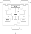
- FIG. 3 shows the configuration of the moving body 1 of the embodiment.
- the moving body 1 has a rectangular box-shaped base 2, and three wheels 30 are rotatably attached to the base 2.
- the base body 2 is provided with actuators 32 that drive the wheels 30 , and the controller 40 independently controls the three actuators 32 .
- the control unit 40 is a main processor that processes and outputs various data and commands, and controls the actuators 32 connected to the wheels 30 so as to move the moving body 1 in a desired direction.
- Three wheels 30 and an actuator 32 that drives each wheel 30 constitute a moving mechanism in the mobile body 1 .
- Actuator 32 may be a motor.
- the sensor 42 may include a triaxial acceleration sensor, a gyro sensor, a positioning sensor, etc., and supplies detected sensor data to the control unit 40 .
- the camera 44 photographs the surroundings and supplies the photographed image to the control unit 40 .
- a plurality of cameras 44 may be arranged so as to capture images of all directions of the base 2 so that the control unit 40 can acquire captured images of the entire periphery of the base 2 .
- control unit 40 may control the actuator 32 based on the sensor data supplied from the sensor 42 and the captured image supplied from the camera 44 to cause the moving body 1 to travel autonomously. Further, the control unit 40 may control the actuator 32 based on the operation instruction from the user received by the communication unit 46 to cause the moving body 1 to travel.
- the moving mechanism of the moving body 1 of the embodiment is composed of three wheels 30 to enable omnidirectional movement, and does not have four or more wheels 30.
- the three wheels 30 attached to the base 2 one or two wheels 30 are first configuration wheels and the remaining wheels 30 are second configuration wheels of a different kind than the first configuration wheels.
- the first configuration wheel may be the mecanum wheel 20 and the second configuration wheel may be the omni wheel 10 .
- the omni-wheel 10 may be a wheel comprising a wheel body 11 and a plurality of rollers 12 rotatably attached to the outer periphery of the wheel body 11 through a support shaft perpendicular to the axle.
- the mecanum wheel 20 may be a wheel comprising a wheel body 21 and a plurality of rollers 22 rotatably attached to the outer circumference of the wheel body 21 through a support shaft that is inclined with respect to the axle. .
- the inclination angles of the plurality of support shafts may all be the same.
- each wheel 30 is mounted parallel to the mounting surface of the rectangular box-shaped base 2, so that the direction of one wheel 30 is parallel or perpendicular to the direction of the other wheels 30. relationship. Since the three wheels 30 are attached parallel to the mounting surface of the base 2, the actuators 32 can be arranged in the base 2 in a space efficient manner as compared with the case where the wheels are attached obliquely to the mounting surface. Space can be used effectively.
- a configuration example of the three wheels 30 will be described below. 4 to 9 below show the positions of the wheels 30 and the actuators 32 with respect to the base body 2, and the illustration of the control unit 40, the sensor 42, the camera 44 and the communication unit 46 is omitted.
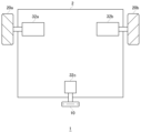
- Fig. 4 shows an example of the wheel configuration of a moving body.
- the moving body 1 includes a pair of right mecanum wheel 20b and left mecanum wheel 20a on the front surface of the base 2, and an omni wheel 10 on the rear surface of the base 2.
- the right mecanum wheel 20b is connected to an actuator 32a
- the left mecanum wheel 20a is connected to an actuator 32b
- the omniwheel 10 is connected to an actuator 32c.
- a pair of right mecanum wheel 20b and left mecanum wheel 20a are arranged to face the same direction.
- the wheel diameters of the right mecanum wheel 20b, the left mecanum wheel 20a, and the omni wheel 10 may be the same.
- the moving body 1 may include a pair of right mecanum wheel 20b and left mecanum wheel 20a on the rear surface of the base 2 and an omni wheel 10 on the front surface of the base 2 .
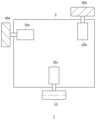
- FIG. 5 shows another example of the wheel configuration of a moving body.
- the moving body 1 has a left mecanum wheel 20 a on the left side of the base 2 , a right mecanum wheel 20 b on the right side of the base 2 , and an omni wheel 10 on the rear side of the base 2 .
- the left mecanum wheel 20a is connected to an actuator 32a
- the right mecanum wheel 20b is connected to an actuator 32b
- the omniwheel 10 is connected to an actuator 32c.
- the left mecanum wheel 20a and the right mecanum wheel 20b are arranged to face the same direction.
- the wheel diameters of the left mecanum wheel 20a, the right mecanum wheel 20b, and the omni wheel 10 may be the same.
- FIG. 1 shows another example of the wheel configuration of a moving body.
- a pair of left mecanum wheel 20a and right mecanum wheel 20b are attached to both side surfaces of the base 2, so that the user can sensuously recognize the front-rear direction of the mobile body 1.
- FIG. The positions of the left mecanum wheel 20a and the right mecanum wheel 20b may be exchanged with each other.
- FIG. 6 shows another example of the wheel configuration of a moving body.
- the moving body 1 has a left mecanum wheel 20 a on the left side of the base 2 , a right mecanum wheel 20 b on the right side of the base 2 , and an omni wheel 10 on the rear side of the base 2 .
- the wheel arrangement shown in FIG. 6 may be the same as the wheel arrangement shown in FIG.
- the left mecanum wheel 20a and the right mecanum wheel 20b have the same wheel diameter. is different.
- the wheel diameter of the omniwheel 10 is larger than the wheel diameter of the mecanum wheel 20 .
- the step that can be overcome during movement in the front-rear direction depends on the diameter of the roller 12 in the omniwheel 10 . Therefore, as shown in FIG. 6, by increasing the wheel diameter of the omniwheel 10 and increasing the diameter of the roller 12, it is possible to improve the gap running performance of the moving body 1 in the front-rear direction.
- FIG. 7 shows another example of the wheel configuration of a moving body.
- the moving body 1 has a left mecanum wheel 20 a on the left side of the base 2 , a right mecanum wheel 20 b on the right side of the base 2 , and an omni wheel 10 on the rear side of the base 2 .
- the wheel arrangement shown in FIG. 7 may be the same as the wheel arrangement shown in FIG.
- the left mecanum wheel 20a and the right mecanum wheel 20b have the same wheel diameter. is different. As shown, the omniwheel 10 has a smaller wheel diameter than the mecanum wheel 20 . According to the wheel configuration shown in FIG. 7, the omniwheel 10 has a small wheel diameter, which reduces the motion characteristics in the left-right direction.
- FIG. 8 shows another example of the wheel configuration of a moving body.
- the moving body 1 has a left mecanum wheel 20 a on the left side of the base 2 , a left mecanum wheel 20 a on the front of the base 2 , and an omni wheel 10 on the rear of the base 2 .
- the left mecanum wheel 20a on the left side is connected to an actuator 32a
- the left mecanum wheel 20a on the front side is connected to an actuator 32b
- the omniwheel 10 is connected to an actuator 32c.
- the two left mecanum wheels 20a are arranged to face in orthogonal directions. Note that instead of the two left mecanum wheels 20a, two right mecanum wheels 20b may be used.
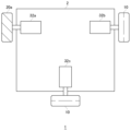
- FIG. 9 shows another example of the wheel configuration of a moving body.
- the moving body 1 has a left mecanum wheel 20 a on the left side of the base 2 , an omni wheel 10 on the right side of the base 2 , and an omni wheel 10 on the rear side of the base 2 .
- the left mecanum wheel 20a is connected to an actuator 32a
- the omniwheel 10 on the right side is connected to an actuator 32b
- the omniwheel 10 on the rear side is connected to an actuator 32c.
- two of the three wheels 30 are the mecanum wheels 20 and one is the omni wheel 10, but in the wheel configuration example shown in FIG. 9, one is a mecanum wheel. 20, two are omni wheels 10; As shown in FIG. 9, even if one of the three wheels 30 is the mecanum wheel 20 and two are the omni-wheels 10, it is possible to achieve omnidirectional movement.
- the present disclosure can be used for a mobile object that has multiple wheels and is capable of omnidirectional movement.
Landscapes
- Engineering & Computer Science (AREA)
- Mechanical Engineering (AREA)
- Chemical & Material Sciences (AREA)
- Combustion & Propulsion (AREA)
- Transportation (AREA)
- Manipulator (AREA)
Priority Applications (1)
| Application Number | Priority Date | Filing Date | Title |
|---|---|---|---|
| US18/697,776 US20250236135A1 (en) | 2021-10-19 | 2022-08-08 | Mobile body |
Applications Claiming Priority (2)
| Application Number | Priority Date | Filing Date | Title |
|---|---|---|---|
| JP2021171192A JP7796509B2 (ja) | 2021-10-19 | 2021-10-19 | 移動体 |
| JP2021-171192 | 2021-10-19 |
Publications (1)
| Publication Number | Publication Date |
|---|---|
| WO2023067875A1 true WO2023067875A1 (ja) | 2023-04-27 |
Family
ID=86059062
Family Applications (1)
| Application Number | Title | Priority Date | Filing Date |
|---|---|---|---|
| PCT/JP2022/030231 Ceased WO2023067875A1 (ja) | 2021-10-19 | 2022-08-08 | 移動体 |
Country Status (3)
| Country | Link |
|---|---|
| US (1) | US20250236135A1 (https=) |
| JP (1) | JP7796509B2 (https=) |
| WO (1) | WO2023067875A1 (https=) |
Citations (4)
| Publication number | Priority date | Publication date | Assignee | Title |
|---|---|---|---|---|
| JP2018131165A (ja) * | 2017-02-17 | 2018-08-23 | 学校法人 中央大学 | 壁面吸着装置及び壁面移動装置 |
| JP2019053391A (ja) * | 2017-09-13 | 2019-04-04 | 日本電産シンポ株式会社 | 移動体 |
| JP2020045089A (ja) * | 2018-07-25 | 2020-03-26 | ザ・ボーイング・カンパニーThe Boeing Company | 非水平面上でクローリングする自走式ロボット車両のための重力補償 |
| JP2020149508A (ja) * | 2019-03-14 | 2020-09-17 | 株式会社東芝 | 移動体、制御装置、周囲物体検出器、及び監視装置 |
Family Cites Families (9)
| Publication number | Priority date | Publication date | Assignee | Title |
|---|---|---|---|---|
| KR100520272B1 (ko) * | 2002-02-15 | 2005-10-11 | 주식회사 비에스텍 | 전방향 이동 승용완구 |
| JP2008179187A (ja) * | 2007-01-23 | 2008-08-07 | Yaskawa Electric Corp | 全方向移動台車およびその走行制御方法 |
| US9367061B2 (en) * | 2014-02-07 | 2016-06-14 | Enovate Medical, Llc | Medical cart for dispensing medication |
| JP6618170B2 (ja) * | 2015-06-07 | 2019-12-11 | 国立大学法人京都大学 | 移動搬送装置 |
| US9573416B1 (en) * | 2015-10-23 | 2017-02-21 | Disney Enterprises, Inc. | Wheel assembly with multi-sphere omniwheels and omnidirectional devices including the wheel assembly |
| US9999557B2 (en) * | 2016-07-14 | 2018-06-19 | Challenging Solutions, Inc. | Robotic mobility device |
| CN110329146B (zh) * | 2019-07-10 | 2022-09-13 | 哈尔滨理工大学 | 一种移动警示牌装置 |
| JP6937344B2 (ja) * | 2019-08-30 | 2021-09-22 | 本田技研工業株式会社 | 摩擦式駆動装置 |
| CN111377006A (zh) * | 2020-04-24 | 2020-07-07 | 太原工业学院 | 一种全地形轮式机器人的底盘 |
-
2021
- 2021-10-19 JP JP2021171192A patent/JP7796509B2/ja active Active
-
2022
- 2022-08-08 US US18/697,776 patent/US20250236135A1/en active Pending
- 2022-08-08 WO PCT/JP2022/030231 patent/WO2023067875A1/ja not_active Ceased
Patent Citations (4)
| Publication number | Priority date | Publication date | Assignee | Title |
|---|---|---|---|---|
| JP2018131165A (ja) * | 2017-02-17 | 2018-08-23 | 学校法人 中央大学 | 壁面吸着装置及び壁面移動装置 |
| JP2019053391A (ja) * | 2017-09-13 | 2019-04-04 | 日本電産シンポ株式会社 | 移動体 |
| JP2020045089A (ja) * | 2018-07-25 | 2020-03-26 | ザ・ボーイング・カンパニーThe Boeing Company | 非水平面上でクローリングする自走式ロボット車両のための重力補償 |
| JP2020149508A (ja) * | 2019-03-14 | 2020-09-17 | 株式会社東芝 | 移動体、制御装置、周囲物体検出器、及び監視装置 |
Also Published As
| Publication number | Publication date |
|---|---|
| US20250236135A1 (en) | 2025-07-24 |
| JP7796509B2 (ja) | 2026-01-09 |
| JP2023061284A (ja) | 2023-05-01 |
Similar Documents
| Publication | Publication Date | Title |
|---|---|---|
| CN107124899B (zh) | 可移动装置、移动拍摄设备、可移动装置控制系统及方法 | |
| US10399620B2 (en) | Spherical robot and method of controlling the same | |
| US9789976B2 (en) | Carrier having non-orthogonal axes | |
| JP4550850B2 (ja) | 圧電モータシステム | |
| WO2019153293A1 (zh) | 云台及其控制方法、无人机 | |
| US11287830B2 (en) | Control method of multipurpose rollable moving device | |
| WO2018064831A1 (zh) | 一种云台、无人机及其控制方法 | |
| US20090297137A1 (en) | Omni-directional camera system | |
| CN206067368U (zh) | 全向轮、包括全向轮的机器人移动平台及移动机器人 | |
| CN206202711U (zh) | 一种云台及无人机 | |
| JP2018118525A (ja) | 飛行作業体、および、それを用いた作業システム | |
| JP4897016B2 (ja) | 圧電モータ | |
| JP6793006B2 (ja) | 光学ユニット | |
| CN111015732B (zh) | 机器人头部机构及其控制方法、机器人 | |
| JP2010030360A (ja) | 球体駆動式全方向移動装置 | |
| WO2023067875A1 (ja) | 移動体 | |
| CN206274111U (zh) | 一种三轴全景摄影增稳云台 | |
| CN101458435B (zh) | 全方向照相机系统 | |
| CN115107496A (zh) | 普通轮驱动无转向舵机的全方位移动底盘结构及控制方法 | |
| JP7032068B2 (ja) | 振れ補正機能付き光学ユニットの回転体基準角度位置調整方法 | |
| JPS6399680A (ja) | 撮影装置 | |
| JP7161754B2 (ja) | 移動走行装置 | |
| WO2024190133A1 (ja) | 移動装置、移動装置の制御方法及び制御プログラム | |
| CN109334808B (zh) | 一种轮足机器人及其控制方法 | |
| KR20170099683A (ko) | 안정된 자세를 유지하는 볼 로봇 |
Legal Events
| Date | Code | Title | Description |
|---|---|---|---|
| 121 | Ep: the epo has been informed by wipo that ep was designated in this application |
Ref document number: 22883187 Country of ref document: EP Kind code of ref document: A1 |
|
| WWE | Wipo information: entry into national phase |
Ref document number: 18697776 Country of ref document: US |
|
| NENP | Non-entry into the national phase |
Ref country code: DE |
|
| 122 | Ep: pct application non-entry in european phase |
Ref document number: 22883187 Country of ref document: EP Kind code of ref document: A1 |
|
| WWP | Wipo information: published in national office |
Ref document number: 18697776 Country of ref document: US |