WO2023067702A1 - プラント運転支援装置 - Google Patents
プラント運転支援装置 Download PDFInfo
- Publication number
- WO2023067702A1 WO2023067702A1 PCT/JP2021/038640 JP2021038640W WO2023067702A1 WO 2023067702 A1 WO2023067702 A1 WO 2023067702A1 JP 2021038640 W JP2021038640 W JP 2021038640W WO 2023067702 A1 WO2023067702 A1 WO 2023067702A1
- Authority
- WO
- WIPO (PCT)
- Prior art keywords
- data
- analysis
- database
- graph
- operator
- Prior art date
- Legal status (The legal status is an assumption and is not a legal conclusion. Google has not performed a legal analysis and makes no representation as to the accuracy of the status listed.)
- Ceased
Links
Images


Classifications
-
- G—PHYSICS
- G05—CONTROLLING; REGULATING
- G05B—CONTROL OR REGULATING SYSTEMS IN GENERAL; FUNCTIONAL ELEMENTS OF SUCH SYSTEMS; MONITORING OR TESTING ARRANGEMENTS FOR SUCH SYSTEMS OR ELEMENTS
- G05B23/00—Testing or monitoring of control systems or parts thereof
- G05B23/02—Electric testing or monitoring
- G05B23/0205—Electric testing or monitoring by means of a monitoring system capable of detecting and responding to faults
- G05B23/0208—Electric testing or monitoring by means of a monitoring system capable of detecting and responding to faults characterized by the configuration of the monitoring system
- G05B23/0216—Human interface functionality, e.g. monitoring system providing help to the user in the selection of tests or in its configuration
-
- G—PHYSICS
- G05—CONTROLLING; REGULATING
- G05B—CONTROL OR REGULATING SYSTEMS IN GENERAL; FUNCTIONAL ELEMENTS OF SUCH SYSTEMS; MONITORING OR TESTING ARRANGEMENTS FOR SUCH SYSTEMS OR ELEMENTS
- G05B23/00—Testing or monitoring of control systems or parts thereof
- G05B23/02—Electric testing or monitoring
- G05B23/0205—Electric testing or monitoring by means of a monitoring system capable of detecting and responding to faults
- G05B23/0259—Electric testing or monitoring by means of a monitoring system capable of detecting and responding to faults characterized by the response to fault detection
- G05B23/0267—Fault communication, e.g. human machine interface [HMI]
- G05B23/0272—Presentation of monitored results, e.g. selection of status reports to be displayed; Filtering information to the user
-
- G—PHYSICS
- G05—CONTROLLING; REGULATING
- G05B—CONTROL OR REGULATING SYSTEMS IN GENERAL; FUNCTIONAL ELEMENTS OF SUCH SYSTEMS; MONITORING OR TESTING ARRANGEMENTS FOR SUCH SYSTEMS OR ELEMENTS
- G05B2223/00—Indexing scheme associated with group G05B23/00
- G05B2223/02—Indirect monitoring, e.g. monitoring production to detect faults of a system
Definitions
- This disclosure relates to a plant operation support device that detects an abnormal state in a plant and performs factor analysis when an abnormality occurs.
- the monitoring and control system collects measured values obtained through sensors attached to each facility of the plant, and collectively monitors them on a display device called a central monitoring monitor.
- these large-scale plants are configured by combining multiple manufacturing processes, and are known to exhibit complex behavior, such as a change in the output of a certain facility that sequentially affects upstream and downstream processes. Therefore, the operator not only checks whether there is an alarm issued by the supervisory control system, but also looks at changes in the measured values and compares them with a plurality of measured values to detect the occurrence of an abnormality.
- factor analysis when an abnormality occurs is one of the tasks that operators and facility administrators are responsible for. Attribution analysis investigates the underlying factors that cause a plant to behave abnormally. Specifically, by analyzing the measured value data collected by the monitoring control system using techniques such as statistical analysis, the presence or absence of an abnormal state and the relationship between abnormal propagation and the like are quantitatively evaluated. For example, as a method for supporting factor analysis, a method for automatically calculating a threshold for determining whether the current plant is normal or abnormal according to a pre-registered calculation method has been disclosed. (For example, see Patent Document 1)
- the method of automatically calculating the threshold according to the pre-registered calculation method described above may not be able to accurately detect an abnormal state when an event occurs that has few occurrences that cannot be directly measured by a sensor. have a nature.
- the present disclosure has been made to solve the problems described above, and aims to provide a display interface that can reduce the operator's burden in analysis work.
- the plant operation support device includes data selection means for the operator to select an arbitrary data range of the first graph in the first graph and the second graph displayed on the display operated by the operator;
- a data selection database that records the operator's operation information including the selection of the data range performed in , a measurement data database that accumulates measurement data measured by the measurement device, and an operation information recorded in the data selection database and the operator can arbitrarily a display data collection unit that collects the measurement data accumulated in the measurement data database selected by the operator; and a graph creation unit.
- the plant operation support device of the present disclosure there is an effect that it is possible to reduce the operator's load in analysis work when factor analysis is performed for an event that has occurred in a plant for which a detection method has not been established.
- FIG. 1 is a block diagram of a plant operation support device according to Embodiment 1 of the present disclosure
- FIG. 1 is a hardware configuration diagram of a plant operation support device according to a first embodiment of the present disclosure
- FIG. FIG. 4 is a diagram showing an example of a schematic representation of a recording method of a data selection history database according to the first embodiment of the present disclosure
- FIG. FIG. 5 is a diagram showing a display example of a data analysis graph created by a data analysis graph creating unit according to the first embodiment of the present disclosure
- FIG. FIG. 5 is a diagram showing an example of a schematic representation of guidance display in the analysis procedure creating unit according to the first embodiment of the present disclosure
- FIG. 7 is a block diagram of a plant operation support device according to a second embodiment of the present disclosure
- FIG. 10 is a diagram showing an example of a schematic representation of a screen change when display data is switched according to the second embodiment of the present disclosure
- FIG. 11 is a block diagram of a plant operation support device according to Embodiment 3 of the present disclosure
- FIG. 11 is a diagram showing an example of a schematic representation of a recording method of an analysis result database according to a third embodiment of the present disclosure
- FIG. It is an example of a guidance display of the plant operation assistance device concerning Embodiment 3 of this indication.
- FIG. 11 is a block diagram of a plant operation support device according to a fourth embodiment of the present disclosure
- FIG. 1 is a block diagram of a plant operation support device according to Embodiment 1 of the present disclosure.
- FIG. 2 is a hardware configuration diagram of the plant operation support device according to the first embodiment of the present disclosure.
- FIG. 3 is a diagram schematically showing an example of a recording method of a data selection history database according to the first embodiment of the present disclosure;
- FIG. 4 is a diagram showing a display example of the data analysis graph created by the data analysis graph creating unit according to the first embodiment of the present disclosure.
- FIG. 5 is a diagram schematically showing an example of guidance display in the analysis procedure creation unit according to the first embodiment of the present disclosure;
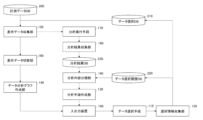
- the plant operation support device shown in FIG. A data selection database (DB) 210 and a data selection history database (DB) 220 for recording information, a measurement data database (DB) 200 for accumulating measurement data measured by a measuring device, and operations recorded in the data selection database 210.
- a display data collection unit 150 that collects the measurement data accumulated in the information and measurement data database 200, and a data analysis graph generation unit 140 that generates a data analysis graph in which data of another graph related to the selected data is displayed.
- an analysis procedure creation unit 130 that creates guidance based on the history of operation information recorded in the data selection history database 220 .
- FIG. 2 is a hardware configuration diagram of the plant operation support device.
- the plant operation support device includes a processor 101 such as a CPU (Control Processing Unit), a memory 102 such as a RAM (Random Access Memory), a display 103 and an input interface (I/F) 104 .
- Selection information collection unit 120 , analysis procedure creation unit 130 , data analysis graph creation unit 140 and display data collection unit 150 are implemented by processor 111 executing a program stored in memory 102 . However, these may be realized by cooperation of, for example, a plurality of processors 101 .
- the data selection means 110 is a function for the operator to arbitrarily select data of interest in the graph displayed on the input/output device 100 by operating the mouse or the like.
- the graphs referred to here are of any type, such as trend graphs, scatter graphs, etc., as long as the operator can arbitrarily select data and perform factor analysis, and the number of graphs to be displayed does not matter.
- the input/output device 100 that displays the graph may be a display device, a display interface, or the like that can display the graph.
- the operator directly specifies an arbitrary period, upper and lower limits, etc. on the trend graph of interest by operating the mouse.
- the operator can directly specify the data range on the scatter diagram by operating the mouse.
- mouse operation was given as an example, but the data range can also be specified by entering mathematical expressions such as thresholds and inequalities.
- the data range can also be specified by entering mathematical expressions such as thresholds and inequalities.
- it includes a series of setting operations related to graph display, such as the display period in trend graphs and the maximum and minimum display ranges in scatter diagrams.
- the operation information including the selection of the data range on the graph performed by the operator with the data selection means 110 is collected in the selection information collection unit 120, and the operation information collected in the selection information collection unit 120 is stored in the data selection database 210. is recorded.
- the operator's operation information collected by the selection information collection unit 120 is recorded in the data selection database 210 and the data selection history database 220, but only the latest operation information performed by the operator is recorded in the data selection database 210. be.
- the selected data collection unit 120 extracts the ID and period of the selected data, converts the selected data range into a formula and collects it. Then, the collected operation information is recorded in the data selection database 210 . For example, if a range of measured A values greater than 50 is selected, the inequality A>50 is recorded in the data selection database 210 .
- the data selection history database 220 is a function that records the history of data selection operation information performed by the operator.
- FIG. 3 is a diagram schematically showing data selection information recorded in the data selection history database 220. As shown in FIG.
- the data selection information consists of display data information 310, data selection ID 320, data selection content information 330, and data selection range information 340, and is recorded in the data selection history database 220 together with the data selection history ID 300.
- the display data information 310 registers measurement values used for displaying graphs such as trend graphs and scatter diagrams.
- the data selection ID 320 manages the data selected by the operator on the graph as a group. To explain with an example, when a plurality of different data on the graph are selected, they are grouped into G1 and G2, and the registration contents are recorded respectively.
- the data selection content information 330 and the data selection range information 340 record which range of which data on the graph is designated by each group recorded by the data selection ID 320, that is, the selected data information. Description will be made with reference to FIG. In FIG. 4, it is assumed that a trend graph displaying measured values A and B and a scatter diagram having measured values A on the vertical axis and measured values B on the horizontal axis are displayed on the input/output device 100 . When the operator designates a shaded range on the trend graph, the measured value A and the measured value B are recorded in the display data information 310, and the measured value A and the measured value B are recorded in the data selection content information 330. be.
- the data selection range information 340 records an inequality corresponding to the range selected by the operator on the scatter diagram.
- the measurement data database 200 is a function for accumulating measurement data measured by the measuring device.
- the measuring device may be any device or means capable of measuring the state of the plant.
- the display data collection unit 150 is a function that collects the operator's latest operation information recorded in the data selection database 210 and the measurement data accumulated in the measurement data database 200 .
- the data analysis graph creation unit 140 uses the data collected by the display data collection unit 150 to, when the operator selects arbitrary data on the graph displayed on the input/output device 100, create a graph related to the selected data. The ability to create data analysis graphs that display data from other graphs.
- FIG. 4 is a diagram showing a display example of the data analysis graph created by the data analysis graph creating unit 140. As shown in FIG.
- FIG. 4 A trend graph and a scatter diagram are displayed on the input/output device 100 .
- the trend graph displays two measurement data, measured value A and measured value B
- the scatter diagram displays a graph having the measured value A on the vertical axis and the measured value B on the horizontal axis.
- operation information such as the selected data type and time period is recorded in the data selection database 210 .
- the scatter diagram refers to the operation information recorded in the data selection database 210, and changes the display color of data (markers) related to the data selected by the operator to highlight them. In the scatter plot of FIG. 4, the hollow markers are highlighted.
- the data selection database 210 records the selection range of the measured values A and B.
- the trend graph changes the display color of the corresponding time zone according to the selection range recorded in the data selection database 210 to highlight it.
- FIG. 4 shows an example in which the data of another graph related to the selected data is displayed by changing the color, it is not limited to the display by changing the color. As long as the data of another graph related to the selected data is displayed in an emphasized manner, for example, the method of displaying the data so as to blink is not limited.
- the analysis procedure creation unit 130 creates guidance based on the history of operation information recorded in the data selection history database 220 and displays the guidance on the input/output device 100 .
- FIG. 5 schematically shows a procedure created by the analysis procedure creating unit 130 based on the history of data selection information recorded in the data selection history database 220 and analyzed.
- Guidance display in the present invention means displaying on the input/output device 100 guidance information indicating the selection procedure and selection operation details of the data recorded in the data selection history database 220 .
- the measured value B and the measured value C are displayed in the procedure 1
- the measured value A, the measured value B and the measured value C are displayed in the procedure 2
- the measured value A and the measured value C are displayed in the procedure 3.
- procedure 4 it is shown that the data range of the display of the measured value A and the measured value C and the area of the measured value A>50 and the measured value C>50 is selected.
- Procedure 5 indicates that the measured value A and the measured value C are displayed and that the data range of the measured value A>50 and the measured value C>90 is selected.
- the operation for additional display of data is arranged on the left side, and the operation for limited display of data is arranged on the right side, and the operation information is displayed in a branch format.
- the procedure starts from procedure 1 (500C), and since the measurement value A is newly added in procedure 2 (500A), it is placed on the left side of procedure 1 (display 500C). do.
- procedure 3 (500B) an operation was performed to delete the measurement value B from procedure 2 (500A), so it is arranged on the right side of procedure 2 (500A).
- procedure 4 (510A) and procedure 5 (510B) the data range is selected from the data in procedure 3 (500B). An inequality indicating is also displayed.
- FIG. 5 shows an example of display in a branch format
- other display formats such as a list format and a flow chart format are also conceivable.
- the operator when the operator performs factor analysis, when the operator selects data on one graph displayed on the input/output device 100, the relation of another graph displayed on the display data is displayed. It also records operation information, and displays operation details and operation procedures as guidance. Therefore, it becomes easy to visualize the correlation of the data of the plurality of graphs displayed on the input/output device 100, and by suppressing the mixing of erroneous data, it is possible to reduce the number of occurrences of reworking and the like. Thereby, the operator's workload in data analysis can be reduced.
- Embodiment 1 has shown the plant operation support device capable of reducing the operator's workload in data analysis.
- Embodiment 2 shows a plant operation support device for solving the problem that it is necessary to repeatedly switch display data in the process in which an operator searches for data necessary for factor analysis from a huge amount of measured value data.
- a display data switching unit 160 is added to the plant operation support device of the first embodiment.
- the same numbers are assigned to the same configurations as in the first embodiment, and the description thereof is omitted.
- FIG. 6 is a block diagram of a plant operation support device according to Embodiment 2 of the present disclosure.
- FIG. 7 is a diagram schematically showing an example of screen changes when display data is switched according to the second embodiment of the present disclosure.
- the display data switching unit 160 is a function that continuously switches the display of time-series changes in data displayed in graphs such as trend graphs and scatter diagrams using an animation method or the like.
- FIG. 7 two axes of measured value A and measured value B are selected, and data at each time (data 600A at time 6:00, data 600C at time 7:00, data 600B at time 8:00) are It is indicated by a black circle marker.
- data at each time data 610A at time 6:00, data 610C at time 7:00, data 610B at time 8:00
- data before switching is represented by a white marker
- movement data after switching is represented by a black marker.
- the chronological change of the data from the white marker to the black marker at each time is continuously displayed by an animation method.
- Such animation display is also realized by moving the display camera position in the three-dimensional scatter diagram.
- a three-dimensional scatter diagram having measured value A and measured value B in the plane direction and measured value C in the normal direction
- measured value A and measured value C in the plane direction and measured value B in the normal direction It means that the measured value B and the measured value C are switched so that
- Embodiment 3 In data analysis, the mean value, variance value, and correlation coefficient value in statistical analysis and the evaluation value of the objective function in optimization problems are used as a means of quantitatively expressing the distribution or characteristics of data. etc. When an operator performs work such as factor analysis, he or she may use quantitative evaluation values to add meaning to the distribution characteristics of the graph.
- Embodiment 3 shows a plant operation support measure that reduces the operator's data analysis workload in data analysis using quantitative evaluation values.
- the present embodiment is configured by adding an analysis executing means 170, an analysis result collection unit 180, and an analysis result database (DB) 230 to the plant operation support device shown in the second embodiment.
- DB analysis result database
- FIG. 8 is a block diagram of a plant operation support device according to Embodiment 3 of the present disclosure.
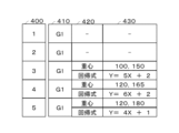
- FIG. 9 is a diagram schematically showing an example of a recording method of the analysis result database 230 according to the third embodiment of the present disclosure.
- FIG. 10 is an example of guidance display of the plant operation support device according to the present embodiment.
- the analysis execution means 170 is a function that calculates the distribution of the data collected by the display data collection unit 150, the correlation between the data, such as the relationship between the data.
- the correlation of the collected data is calculated by quantitative evaluation using the average value of the data and evaluation values such as regression equations.
- the analysis result collection unit 180 is a function that classifies the data correlation results calculated by the analysis execution means 170 and records them in the analysis result database 230 .
- the analysis result database 230 records analysis results relating to the correlation of data calculated by the analysis executing means 170, that is, data average values, evaluation values such as regression equations, and the like.
- Data selection history ID 400 , data selection ID 410 , analysis method name information 420 and analysis result information 430 are recorded in analysis result database 230 .
- the analysis method name information 420 is the analysis method used when calculating the analysis result in the analysis execution means 170, such as average value, center of gravity, regression equation, and the like.
- the analysis result information 430 is an evaluation value representing the analysis result calculated by the analysis execution means 170 using the analysis method.
- the data selection history ID 400 and the data selection ID 410 recorded in the analysis result database 230 have the same content as the data recorded in the data selection history database 220 .
- Grouping is performed by the data selection ID 410, and analysis method name information 420 and analysis result information 430 are recorded in each group.
- the center of gravity and regression equation of group 1 (G1) are calculated.
- the center of gravity and the regression equation are recalculated as the data selection range is limited in Procedures 4 and 5.
- FIG. 5 shows an example in which the data selection range is displayed by an inequality as an example of the guidance information created in the analysis procedure creation unit 130.
- the correlation of the data recorded in the analysis result database 230 Guidance display is performed on the input/output device 100 by adding an evaluation value indicating .
- FIG. 10 is an example of guidance display of the plant operation support device according to the present embodiment. By adding the evaluation values recorded in the analysis result database 230 and displaying the guidance as shown in FIG. 10, the selected data and the evaluation values for each operating procedure of the operator can be linked and displayed. Further, although FIG. 10 shows an example of display using a graph, display using character information may be performed as shown in FIG.
- the evaluation value which is the analysis result of the data correlation
- the data range selected by the operator and displaying the guidance
- the data selection range and the evaluation value are linked, and the executed data selection is performed. You will be able to quickly determine if it worked. As a result, the effect of reducing the workload of the operator in factor analysis can be obtained.
- Embodiment 4 has described the plant operation support device in which the analysis procedure creation unit 130 performs guidance display using data addition and limiting operations as delimiters.
- a plant operation support device that displays guidance by combining an evaluation value with a data selection range has been described. Evaluation values may be classified.
- This embodiment shows a plant operation support device configured by adding an analysis content classification unit 190 for classifying evaluation values to the plant operation support device of the third embodiment. The same numbers are given to the same configurations as in the third embodiment, and the description thereof is omitted.
- FIG. 11 is a block diagram of a plant operation support device according to Embodiment 4 of the present disclosure. As shown in FIG. 11, the present embodiment is configured by adding an analysis content classification unit 190 to the plant operation support device shown in the third embodiment. Analysis content classification unit 190 is configured between analysis result database 230 and data selection history database 220 and analysis procedure creation unit 130 .
- the analysis content classification unit 190 is a function that classifies the evaluation values in each operation procedure calculated by the analysis method recorded in the analysis result database 230 for each analysis method.
- the evaluation value is calculated using the center of gravity and the regression equation as the analysis method
- the evaluation value is calculated using only the center of gravity as the analysis method, and the analysis result database. 230 is recorded.
- the analysis content classification unit 190 classifies evaluation values for each analysis technique, that is, for each analysis technique name information 420 .
- the center of gravity is used as the analysis method for the evaluation values of procedures 1-3
- the center of gravity as the analysis method is the evaluation values for procedures 1 and 2 for classification.
- the evaluation value information classified for each analysis method by the analysis content classification unit 190 is divided by the data selection operation shown in FIG. It makes it easier to grasp the whole work and can be expected to improve work efficiency.
- 100 input/output device 101 processor, 102 memory, 103 display, 104 input interface, 110 data selection means, 120 selected information collection unit, 130 analysis procedure creation unit, 140 data analysis graph creation unit, 150 display data collection unit, 160 display Data switching unit, 170 Analysis execution means, 180 Analysis result collection unit, 190 Analysis content classification unit, 200 Measurement data database, 210 Data selection database, 220 Data selection history database, 230 Analysis result database, 300, 400 Data selection history ID, 310 Display data information, 320, 410 Data selection ID, 330 Data selection content information, 340 Data selection range information, 420 Analysis method name information, 430 Analysis result information, 500A to 500C Data selection procedure display, 510A to 520B Data selection range Data selection procedure display, 600A to 600C Scatter diagram display data consisting of measurement values A and B, 610A to 610C Scatter diagram display data consisting of measurement values A and C, 710 Trend graph display example, 720 Scatter diagram
Landscapes
- Engineering & Computer Science (AREA)
- Physics & Mathematics (AREA)
- General Physics & Mathematics (AREA)
- Automation & Control Theory (AREA)
- Human Computer Interaction (AREA)
- Testing And Monitoring For Control Systems (AREA)
Priority Applications (4)
| Application Number | Priority Date | Filing Date | Title |
|---|---|---|---|
| PCT/JP2021/038640 WO2023067702A1 (ja) | 2021-10-19 | 2021-10-19 | プラント運転支援装置 |
| JP2022536552A JP7173414B1 (ja) | 2021-10-19 | 2021-10-19 | プラント運転支援装置 |
| CN202180103281.1A CN118140188A (zh) | 2021-10-19 | 2021-10-19 | 设施运转支援装置 |
| US18/697,738 US20240402695A1 (en) | 2021-10-19 | 2021-10-19 | Plant operation assistance device |
Applications Claiming Priority (1)
| Application Number | Priority Date | Filing Date | Title |
|---|---|---|---|
| PCT/JP2021/038640 WO2023067702A1 (ja) | 2021-10-19 | 2021-10-19 | プラント運転支援装置 |
Publications (1)
| Publication Number | Publication Date |
|---|---|
| WO2023067702A1 true WO2023067702A1 (ja) | 2023-04-27 |
Family
ID=84082874
Family Applications (1)
| Application Number | Title | Priority Date | Filing Date |
|---|---|---|---|
| PCT/JP2021/038640 Ceased WO2023067702A1 (ja) | 2021-10-19 | 2021-10-19 | プラント運転支援装置 |
Country Status (4)
| Country | Link |
|---|---|
| US (1) | US20240402695A1 (https=) |
| JP (1) | JP7173414B1 (https=) |
| CN (1) | CN118140188A (https=) |
| WO (1) | WO2023067702A1 (https=) |
Cited By (1)
| Publication number | Priority date | Publication date | Assignee | Title |
|---|---|---|---|---|
| WO2025229743A1 (ja) * | 2024-05-01 | 2025-11-06 | 株式会社日立ハイテク | オペレーション分析システム及びオペレーションデータ収集方法 |
Citations (4)
| Publication number | Priority date | Publication date | Assignee | Title |
|---|---|---|---|---|
| JP2000172319A (ja) * | 1998-12-02 | 2000-06-23 | Toshiba Corp | 故障時対応ガイダンス装置 |
| JP2007193512A (ja) * | 2006-01-18 | 2007-08-02 | Mitsubishi Electric Corp | プラント運転支援装置 |
| JP2012138044A (ja) * | 2010-12-28 | 2012-07-19 | Toshiba Corp | プロセス状態監視装置 |
| JP2013008234A (ja) * | 2011-06-24 | 2013-01-10 | Omron Corp | データ比較装置、データ比較方法、制御プログラムおよび記録媒体 |
-
2021
- 2021-10-19 JP JP2022536552A patent/JP7173414B1/ja active Active
- 2021-10-19 CN CN202180103281.1A patent/CN118140188A/zh active Pending
- 2021-10-19 US US18/697,738 patent/US20240402695A1/en active Pending
- 2021-10-19 WO PCT/JP2021/038640 patent/WO2023067702A1/ja not_active Ceased
Patent Citations (4)
| Publication number | Priority date | Publication date | Assignee | Title |
|---|---|---|---|---|
| JP2000172319A (ja) * | 1998-12-02 | 2000-06-23 | Toshiba Corp | 故障時対応ガイダンス装置 |
| JP2007193512A (ja) * | 2006-01-18 | 2007-08-02 | Mitsubishi Electric Corp | プラント運転支援装置 |
| JP2012138044A (ja) * | 2010-12-28 | 2012-07-19 | Toshiba Corp | プロセス状態監視装置 |
| JP2013008234A (ja) * | 2011-06-24 | 2013-01-10 | Omron Corp | データ比較装置、データ比較方法、制御プログラムおよび記録媒体 |
Cited By (1)
| Publication number | Priority date | Publication date | Assignee | Title |
|---|---|---|---|---|
| WO2025229743A1 (ja) * | 2024-05-01 | 2025-11-06 | 株式会社日立ハイテク | オペレーション分析システム及びオペレーションデータ収集方法 |
Also Published As
| Publication number | Publication date |
|---|---|
| CN118140188A (zh) | 2024-06-04 |
| JPWO2023067702A1 (https=) | 2023-04-27 |
| US20240402695A1 (en) | 2024-12-05 |
| JP7173414B1 (ja) | 2022-11-16 |
Similar Documents
| Publication | Publication Date | Title |
|---|---|---|
| US11275357B2 (en) | Event analyzing device, event analyzing system, event analyzing method, and non-transitory computer readable storage medium | |
| JP5868784B2 (ja) | プロセス監視システム及び方法 | |
| JP5778087B2 (ja) | プロセス監視システム及び方法 | |
| CN110322583A (zh) | 异常探测系统、支持装置以及异常探测方法 | |
| JP5875726B1 (ja) | 異常予兆診断装置のプリプロセッサ及びその処理方法 | |
| CN101772742B (zh) | 用于提供与来自过程控制系统的告警有关的统计的告警分析系统和方法 | |
| KR102266182B1 (ko) | 복수의 시계열 데이터의 모니터링 방법 및 장치 | |
| WO2022038804A1 (ja) | 診断装置及びパラメータ調整方法 | |
| CN114551271A (zh) | 监测机台运行状况的方法及装置、存储介质及电子设备 | |
| JPWO2010032701A1 (ja) | 運用管理装置、運用管理方法、および運用管理プログラム | |
| US20110209083A1 (en) | Process analysis system | |
| KR101233264B1 (ko) | 섹터 그래프 기반 플랜트 및 건축물 설비 운영상태 감시 장치 및 방법 | |
| CN115640860B (zh) | 一种工业云服务的机电设备远程维护方法及系统 | |
| JP7173414B1 (ja) | プラント運転支援装置 | |
| JP6052177B2 (ja) | 監視装置、監視方法およびプログラム | |
| CN112114578B (zh) | 一种多工序多变量过程在线监控和异常源诊断的稳健方法 | |
| KR101281460B1 (ko) | 통계적 공정 관리도를 이용하여 이상증후를 탐지하는 방법 | |
| JP2002015000A (ja) | 多変数時系列データ類似度判定装置 | |
| KR20210059267A (ko) | 데이터 수집 시스템 및 방법 | |
| JP7771576B2 (ja) | 装置管理システム、装置の障害原因推定方法、及びプログラム | |
| CN113574484B (zh) | 支援装置、显示装置、支援方法及计算机程序产品 | |
| CN109828146A (zh) | 一种通过设备电参数ad采样判断设备工况的方法 | |
| JP7559958B2 (ja) | 製品品質分析支援システム | |
| KR101557214B1 (ko) | 공정 이상 전파 경로 분석 방법 및 시스템 | |
| JP2025006111A (ja) | 検査監視装置 |
Legal Events
| Date | Code | Title | Description |
|---|---|---|---|
| WWE | Wipo information: entry into national phase |
Ref document number: 2022536552 Country of ref document: JP |
|
| 121 | Ep: the epo has been informed by wipo that ep was designated in this application |
Ref document number: 21961355 Country of ref document: EP Kind code of ref document: A1 |
|
| WWE | Wipo information: entry into national phase |
Ref document number: 202180103281.1 Country of ref document: CN |
|
| NENP | Non-entry into the national phase |
Ref country code: DE |
|
| 122 | Ep: pct application non-entry in european phase |
Ref document number: 21961355 Country of ref document: EP Kind code of ref document: A1 |