WO2023062720A1 - 音響制御装置 - Google Patents
音響制御装置 Download PDFInfo
- Publication number
- WO2023062720A1 WO2023062720A1 PCT/JP2021/037740 JP2021037740W WO2023062720A1 WO 2023062720 A1 WO2023062720 A1 WO 2023062720A1 JP 2021037740 W JP2021037740 W JP 2021037740W WO 2023062720 A1 WO2023062720 A1 WO 2023062720A1
- Authority
- WO
- WIPO (PCT)
- Prior art keywords
- dial
- bpm
- control device
- unit
- music
- Prior art date
- Legal status (The legal status is an assumption and is not a legal conclusion. Google has not performed a legal analysis and makes no representation as to the accuracy of the status listed.)
- Ceased
Links
Images


Classifications
-
- H—ELECTRICITY
- H04—ELECTRIC COMMUNICATION TECHNIQUE
- H04R—LOUDSPEAKERS, MICROPHONES, GRAMOPHONE PICK-UPS OR LIKE ACOUSTIC ELECTROMECHANICAL TRANSDUCERS; ELECTRIC HEARING AIDS; PUBLIC ADDRESS SYSTEMS
- H04R3/00—Circuits for transducers
Definitions
- the present invention relates to an acoustic control device.
- Non-Patent Document 1 a sound control device capable of adjusting the playback speed of music is known (see Non-Patent Document 1, for example).
- the sound control device described in Non-Patent Document 1 includes a rotatable encoder, and can adjust the playback speed of music according to the rotation of the encoder.
- the tempo which corresponds to the playback speed of the song, increases in decimal places.
- the encoder is rotated counter-clockwise, the tempo is decreased in decimal places.
- the sound control device also has a SHIFT button, and when the SHIFT button is pressed and the encoder is rotated clockwise, the tempo is increased in units above the decimal point.
- the SHIFT button is pressed and the encoder is rotated counterclockwise, the tempo is decreased in units above the decimal point.
- a sound control device is a sound control device capable of adjusting the playback speed of a piece of music, comprising: a dial provided rotatably for receiving an operation for adjusting the playback speed of the piece of music; and a control unit that changes an amount of change in the reproduction speed of the music piece for each unit rotation angle of the dial according to the rotation state.
- FIG. 5 is a diagram showing an example of display contents in a slider display mode according to the first embodiment
- FIG. 10 is a diagram for explaining the relationship between the ratio of the adjusted BPM to the original BPM and the displayed graphic according to the modification of the first embodiment
- FIG. 10 is a diagram for explaining the relationship between the ratio of the adjusted BPM to the original BPM and the displayed graphic according to the modification of the first embodiment
- the schematic diagram which shows the dial with which the sound control apparatus which concerns on 2nd Embodiment is provided.
- FIG. 4 is a schematic diagram showing a modification of the acoustic control device according to the first and second embodiments;
- FIG. 1 is a schematic diagram showing the configuration of an acoustic control device 1 according to this embodiment.
- the sound control device 1 according to this embodiment is configured to be able to adjust the playback speed of the input music. Specifically, the sound control device 1 adjusts the playback speed of the music by adjusting the BPM (Beats Per Minute) of the music.
- BPM Beats Per Minute
- the BPM of a piece of music represents the tempo during reproduction of the piece of music, that is, the number of beats per minute during reproduction of the piece of music.
- the sound control device 1 individually controls the reproduction of the first music loaded on the first channel and the reproduction of the second music loaded on the second channel, and reproduces the music on the first channel.
- the mixer mixes the first music played on the second channel and the second music reproduced on the second channel, and outputs an audio signal corresponding to the mixed music.
- the sound control device 1 includes a housing 2, two channel operation units 3 (3A and 3B), and a crossfader 4, as shown in FIG.
- the sound control device 1 includes a control section 5 (see FIG. 2) that controls the operation of the sound control device 1. As shown in FIG.
- the housing 2 is formed in a substantially rectangular parallelepiped shape and accommodates the controller 5 inside.
- the housing 2 has a top surface 21, an upper surface 22, a lower surface 23, a left side surface 24, a right side surface 25, and a bottom surface (not shown).
- Two channel operation units 3 ( 3 A, 3 B) and a crossfader 4 are arranged on the top surface 21 .
- the two channel operation units 3 (3A, 3B) operate the playback state of the music loaded to the corresponding channels.
- the two channel operation units 3 are a first channel operation unit 3A for operating the playback state of the first music loaded on the first channel, and a second channel operation unit 3A for operating the playback state of the second music loaded on the second channel.
- Each channel operation section 3 has a jog dial 31 , an equalizer adjustment section 32 , a channel fader 33 and a playback speed operation section 34 .
- the jog dial 31 is a dial that is rotatably provided on the top surface 21 and used to adjust the playback direction and playback speed of the song being played. It should be noted that when the user combines the change of the rotation direction and the change of the rotation speed of the jog dial 31, a scratch operation peculiar to the DJ performance is performed.
- the equalizer adjustment unit 32 performs equalizer adjustment processing for the corresponding channel.
- the equalizer adjustment section 32 has a level adjustment section 321 , a high frequency band adjustment section 322 , an intermediate frequency band adjustment section 323 , a low frequency band adjustment section 324 and an effect adjustment section 325 .
- the level adjustment section 321 adjusts the input level of the input music.
- the high frequency band adjustment unit 322 adjusts the volume of the high frequency band of the input music.
- a high frequency band is, for example, a frequency band of 4649 Hz or higher.
- the medium frequency band adjustment unit 323 adjusts the volume of the medium frequency band of the input music.
- the medium frequency band is, for example, a frequency band above 284 Hz and below 4649 Hz.
- the low frequency band adjustment unit 324 adjusts the volume of the low frequency band of the input music.
- the low frequency band is, for example, a frequency band of 284 Hz or less.
- the effect adjustment section 325 adjusts the amount of effect set in the corresponding channel operation section 3 .
- the channel fader 33 adjusts the volume output from the corresponding channel operation section 3 .
- the reproduction speed operation unit 34 receives an operation for adjusting the reproduction speed of the music loaded on the corresponding channel.
- the playback speed operation section 34 has a dial 341 , a detection section 342 , a notification section 343 , a display section 344 and a switching operation section 345 .
- the dial 341 accepts an operation for adjusting the playback speed of music.
- the dial 341 is rotatable clockwise and counterclockwise when viewed from a position facing the top surface 21 . More specifically, the dial 341 can rotate clockwise or counterclockwise any number of times until the rotation is restricted by the notification unit 343, which will be described later.
- a detection unit 342 detects the rotation state of the dial 341 .
- the detection unit 342 has a rotary encoder and detects the rotation acceleration and rotation angle of the dial 341 .
- the detection unit 342 outputs the detected rotational acceleration and rotation angle to the control unit 5 .
- the control unit 5 adjusts the BPM of the music loaded to the corresponding channel based on the detection result of the detection unit 342 to change the reproduction speed of the music.
- the notification unit 343 notifies the user that the ratio has reached a predetermined value by restricting the rotation of the dial 341 .
- Notification by the notification unit 343 will be described in detail later.
- the display unit 344 displays information about the playback speed of music under the control of the control unit 5 .
- the contents displayed by the display unit 344 will be described in detail later.
- the switching operation section 345 switches the content displayed by the display section 344 . In other words, the switching operation section 345 switches the display mode of the display section 344 .
- the display mode will be detailed later.
- the crossfader 4 has an operator 41 that can move left and right. As the operator 41 is moved to the left, the ratio of the volume of the first channel in the volume output from the sound control device 1 increases. Further, as the operator 41 is moved to the right, the ratio of the sound volume of the second channel in the sound volume output from the sound control device 1 increases.
- the first playback unit 51 plays back the first music loaded on the first channel.
- the first adjuster 52 adjusts the playback speed of the first music.
- the first adjustment unit 52 adjusts the playback state of the first music according to the user's operation on the first channel operation unit 3A.
- the first adjustment unit 52 adjusts the playback speed and playback direction of the first music played by the first playback unit 51 according to the user's operation on the jog dial 31 of the first channel operation unit 3A.
- the first adjustment unit 52 adjusts the BPM of the first music reproduced by the first reproduction unit 51 based on the detection result of the first detection unit 342A that detects the rotation state of the first dial 341A. , to adjust the playback speed of the first song.
- a method of adjusting the playback speed of the first music piece by the first adjustment unit 52 will be described in detail later.
- the first control unit 53 controls the reproduction of the first music data by the first reproduction unit 51 and the output of the music obtained by reproducing the first music data.
- the first control unit 53 causes the first reproduction unit 51 to reproduce the first music in the reproduction state adjusted by the first adjustment unit 52 .
- the first control unit 53 controls the output of the music obtained by reproducing the first music by the first reproduction unit 51 according to the user's operation on the equalizer adjustment unit 32 of the first channel operation unit 3A.
- the first control section 53 controls the first notification section 343A. The control of the first notification unit 343A by the first control unit 53 will be detailed later.
- the second playback unit 54 plays back the second music loaded on the second channel.
- the second adjuster 55 adjusts the playback speed of the second music.
- the second adjustment section 55 adjusts the reproduction state of the second music data according to the user's operation on the second channel operation section 3B.
- the second adjustment unit 55 adjusts the BPM of the second music reproduced by the second reproduction unit 54 based on the detection result of the second detection unit 342B that detects the rotation state of the second dial 341B, Adjust the playback speed of the second song.
- a method of adjusting the playback speed of the first music piece by the second adjusting section 55 will be described in detail later.
- the second control unit 56 controls the reproduction of the second music by the second reproduction unit 54 and the output of the music obtained by reproducing the second music. It controls the part 343B.
- the mode switching portion 57 switches the display mode of the first display portion 344A according to the operation on the first switching operation portion 345A. Further, the mode switching portion 57 switches the display mode of the second display portion 344B according to the operation on the second switching operation portion 345B. That is, the display mode is individually set for each of the first channel operation section 3A and the second channel operation section 3B.
- the display modes switched by the mode switching unit 57 will be described in detail later.
- the first adjuster 52 adjusts the playback speed of the first music based on the rotation state of the first dial 341A detected by the first detector 342A. Specifically, the first adjustment unit 52 acquires the rotation direction of the first dial 341A, the rotation acceleration of the first dial 341A, and the rotation angle of the first dial 341A as the detection results of the first detection unit 342A. Then, the first adjustment unit 52 calculates the rotation speed of the first dial 341A based on the rotation acceleration of the first dial 341A, and calculates the rotation speed of the first song based on the rotation direction, rotation speed and rotation angle of the first dial 341A. is adjusted to adjust the playback speed of the first music piece. That is, the rotational state of the first dial 341A referred to when the first adjustment unit 52 adjusts the reproduction speed of the first music includes the rotational speed of the first dial 341A.
- the first adjustment unit 52 adjusts the playback speed of the current first music piece.
- the BPM is increased to increase the playback speed of the current first music piece.
- Clockwise corresponds to the first rotation direction.
- the first adjustment unit 52 decreases the BPM of the current first music piece. to decrease the playback speed of the current first song. Counterclockwise corresponds to a direction opposite to the first rotation direction.
- the first adjustment unit 52 changes the playback speed of the first music based on the rotation speed and rotation angle of the first dial 341A. Specifically, while the rotation speed of first dial 341A is less than the predetermined speed, first adjustment unit 52 adjusts the amount of change in the playback speed of the first music piece for each unit rotation angle of first dial 341A to the first change. Quantity. That is, while the rotation speed of the first dial 341A is less than the predetermined speed, the first adjustment unit 52 sets the amount of change in the BPM of the first song for each unit rotation angle of the first dial 341A as the first amount of change. .
- the first adjustment unit 52 adjusts the current BPM of the first music every time the rotation angle of the first dial 341A reaches the unit rotation angle. Add or subtract the first change amount. For example, when the unit rotation angle is 3° and the first change amount is 0.1, while the rotation speed of the first dial 341A is less than the predetermined speed, the first adjustment unit 52 rotates the first dial Each time 341A is rotated by 3°, the BPM of the first music is added or subtracted by 0.1. Therefore, for example, when the first dial 341A is rotated 90° clockwise at a rotation speed less than the predetermined speed, the BPM of the first music is 3 is added to the BPM of the first music piece.
- the BPM of the first music is rotated 30° counterclockwise by the first dial 341A. It is a value obtained by subtracting 1 from the BPM of the previous first music piece.
- the first adjustment unit 52 adjusts the amount of change in the reproduction speed of the first music piece for each unit rotation angle of the first dial 341A from the first amount of change. is also a large second amount of change. That is, while the rotation speed of the first dial 341A is equal to or higher than the predetermined speed, the first adjustment unit 52 sets the amount of change in the BPM of the first song for each unit rotation angle of the first dial 341A as the second amount of change. .
- FIG. 3 is a diagram showing a rotating operation of the first dial 341A when adjusting the playback speed of the first music piece.
- the amount of change in the BPM of the first music piece and the amount of change in the playback speed of the first music piece change according to the rotation speed of the first dial 341A.
- the rotation speed of the first dial 341A by setting the rotation speed of the first dial 341A to be less than a predetermined speed when the first dial 341A is rotated by the rotation angle ⁇ , the BPM of the first music piece per unit rotation angle is reduced. can be used as the first change amount. Thereby, the BPM of the first music can be finely changed.
- the first control unit 53 When the first dial 341A is rotated as described above, the BPM of the first music is increased, and the first post-adjustment ratio reaches the predetermined value, the first control unit 53 operates the first notification unit 343A. to restrict further rotation of the first dial 341A in the same direction. That is, when the first post-adjustment ratio reaches the predetermined value, the first control unit 53 controls the further rotation of the first dial 341A in the same direction by the first notification unit 343A. Therefore, the notification unit 343 can be called a regulation unit.
- the first control unit 53 regulates further clockwise rotation of the first dial 341A by the first notification portion 343A. This notifies the user that the first adjusted percentage has reached the first limit.
- the restriction by the first notification unit 343A is cancelled. "200%" is exemplified as the first limit value.
- the first control unit 53 regulates further counterclockwise rotation of the first dial 341A by the first notification portion 343A. This notifies the user that the first adjusted percentage has reached the second limit.
- the first dial 341A is rotated clockwise from the state in which the counterclockwise rotation of the first dial 341A by the first notification portion 343A is restricted, and the first post-adjustment ratio becomes greater than the second limit value. Then, the regulation by the first notification unit 343A is canceled. "0%" is exemplified as the second limit value.
- the first notification unit 343A instead of restricting the rotation of the first dial 341A, or in addition to restricting the rotation of the first dial 341A, sets the post-first adjustment ratio to the first The user may be notified that the limit or the second limit has been reached.
- the first notification unit 343A may output a notification sound or vibrate the first dial 341A.
- the display modes switched by the mode switching unit 57 include a direct display mode, a ratio display mode, a graphics display mode, and a slider display mode.
- the contents displayed by the first display section 344A will be described, but the same applies to the contents displayed by the second display section 344B.
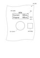
- FIG. 5 is a diagram showing an example of display contents of the first display section 344A in the ratio display mode.
- the ratio display mode is a display mode in which the first display unit 344A displays the first original BPM and the ratio of the first adjusted BPM to the first original BPM (first adjusted ratio), as shown in FIG. be. That is, in the ratio display mode, the display control unit 58 causes the first display unit 344A to display the first original BPM and the first post-adjustment ratio. Therefore, the screen DP2 displayed on the first display portion 344A in the ratio display mode is provided with an original BPM display portion DP11 and a ratio display portion DP22 for displaying the first adjusted ratio.
- the ratio displayed in the ratio display mode is an example of information indicating the ratio of the BPM of the song after the playback speed adjustment to the BPM specific to the song.
- FIG. 6 is a diagram showing an example of display contents of the first display section 344A in the graphics display mode.
- the graphics display mode is a display mode in which the first display unit 344A displays the first original BPM and one of the graphics FG1 and FG2, as shown in FIG. Figures FG1 and FG2 are figures according to the result of comparison between the first original BPM and the first adjusted BPM. More specifically, the figures FG1 and FG2 are figures showing the magnitude relationship between the first original BPM and the first adjusted BPM, the figure FG1 being an upward triangle and the figure FG2 being a downward triangle. Therefore, the screen DP3 displayed on the first display section 344A in the graphic display mode is provided with an original BPM display section DP11 and a graphic display section DP31 for displaying the graphics FG1 and FG2.
- FIG. 7 is a diagram for explaining the relationship between the first post-adjustment ratio and the displayed graphics FG1 and FG2.
- the display control unit 58 causes the first display unit 344A to display the graphic FG1 and not display the graphic FG2, as shown in FIG. . That is, the graphic FG1 is a graphic indicating that the first adjusted BPM is greater than the first original BPM.
- the display control unit 58 makes the brightness of the graphic FG1 displayed on the first display unit 344A the lowest.
- the first threshold is a value greater than 100%, and is 110% in this embodiment. However, the first threshold can be changed as appropriate.
- the display control unit 58 increases the brightness of the graphic FG1 displayed on the first display unit 344A. That is, the brightness of the graphic FG1 displayed when the first post-adjustment ratio is greater than or equal to the first threshold and less than the second threshold is displayed when the first post-adjustment ratio is greater than 100% and less than the first threshold. higher than the brightness of the figure FG1 to be displayed.
- the second threshold is a value larger than the first threshold, and in this embodiment, the second threshold is 120%. However, the second threshold can be changed as appropriate.
- the display control unit 58 maximizes the brightness of the graphic FG1 displayed on the first display unit 344A. That is, the brightness of the graphic FG1 displayed when the first post-adjustment ratio is greater than 100% increases as the difference between the first original BPM and the first post-adjustment BPM increases. It becomes lower as the difference from the BPM after 1 adjustment becomes smaller. In other words, the brightness of the graphic FG1 decreases as the first adjusted BPM approaches the first original BPM, and increases as the first adjusted BPM separates from the first original BPM.
- Such a difference in luminance of the graphic FG1 is an example of information indicating the ratio of the BPM of the song after the playback speed adjustment to the BPM specific to the song.
- the display control unit 58 causes the first display unit 344A to display the downward triangular graphic FG2 and the upward triangular graphic FG1. is not displayed. That is, the graphic FG2 is a graphic showing that the first adjusted BPM is smaller than the first original BPM.
- the display control unit 58 sets the brightness of the graphic FG2 to the lowest.
- the third threshold is a value smaller than 100%, and is 90% in this embodiment. However, the third threshold can be changed as appropriate.
- the display control unit 58 increases the brightness of the graphic FG2. That is, the luminance of the graphic FG2 displayed when the first post-adjustment ratio is greater than the fourth threshold and equal to or less than the third threshold is such that the first post-adjustment ratio is greater than the third threshold and less than 100%. is higher than the brightness of the graphic FG2 displayed in the case.
- the fourth threshold is a value smaller than the third threshold, and is 80% in this embodiment. However, the fourth threshold can be changed as appropriate.
- the display control unit 58 sets the brightness of the graphic FG2 to the highest. That is, the luminance of the graphic FG2 displayed when the first post-adjustment ratio is less than 100% increases as the difference between the first original BPM and the first post-adjustment BPM increases. It becomes lower as the difference from the BPM after 1 adjustment becomes smaller. In other words, the brightness of the graphic FG2 decreases as the first adjusted BPM approaches the first original BPM, and increases as the first adjusted BPM separates from the first original BPM.
- Such a difference in brightness of the graphic FG2 is an example of information indicating the ratio of the BPM of the song after the playback speed adjustment to the BPM specific to the song.
- the graphics FG1 and FG2 are not displayed as shown in FIG.
- the user can determine the first BPM for the first original BPM.
- the magnitude of the post-adjustment BPM can be intuitively grasped.
- the first post-adjustment ratio can be intuitively grasped.
- the brightness of the graphics FG1 and FG2 increases as the difference between the original BPM and the adjusted BPM increases.
- the brightness of the graphics FG1 and FG2 decreases as the adjusted BPM approaches the original BPM. This makes it easier for the user to grasp that the adjusted BPM is a value that is different from the original BPM.
- the brightness of the graphics FG1 and FG2 may increase as the difference between the original BPM and the adjusted BPM decreases, and decrease as the difference between the original BPM and the adjusted BPM increases.
- the luminance of the graphic FG1 displayed when the first post-adjustment ratio is greater than 100% is maximized when the first post-adjustment ratio is smaller than the first threshold, It may be the lowest when it is equal to or greater than the second threshold.
- the brightness of the graphic FG2 displayed when the first post-adjustment ratio is less than 100% is maximized when the first post-adjustment ratio is greater than the third threshold, and when the first post-adjustment ratio is the third It may be the lowest if it is equal to or less than 4 thresholds.
- the figure FG1 or the figure FG2 appears with high luminance. Since it is displayed, the user can easily determine whether or not the first original BPM and the first adjusted BPM match.
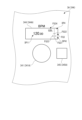
- FIG. 8 is a diagram showing an example of the content displayed by the first display section 344A in the slider display mode.
- the first display unit 344A displays a graphic FG3 as a graphic corresponding to the result of comparison between the first original BPM and the first adjusted BPM. mode.
- a graphic FG3 is a graphic corresponding to the comparison result between the first original BPM and the first adjusted BPM. More specifically, the graphic FG3 is a graphic showing the magnitude relationship between the first original BPM and the first post-adjustment BPM.
- a screen DP4 displayed on the first display portion 344A in the slider display mode is provided with an original BPM display portion DP11 and a graphic display portion DP41 for displaying a graphic FG3.
- the slide operator FG33 slides up and down along the first reference line FG31 to indicate the first post-adjustment ratio.
- the first post-adjustment ratio is 100%, that is, when the first original BPM and the first post-adjustment BPM are the same value
- the slide operator FG33 is moved by the display control unit 58 to the second reference line FG32. placed above.
- the display control unit 58 arranges the slide operator FG33 above the second reference line FG32.
- the display control unit 58 arranges the slide operator FG33 below the second reference line FG32.
- the position of the slide operator FG33 with respect to the second reference line FG32 indicates the magnitude relationship between the first original BPM and the first adjusted BPM.
- the graphic FG3 is a graphic showing the magnitude relationship between the first original BPM and the first adjusted BPM, as described above.
- the range display portion FG34 displays the range of the first post-adjustment ratio indicated by the slide operator FG33 slidably arranged on the first reference line FG31.
- the range of the first post-adjustment ratio indicated by the slide operator FG33 arranged on the first reference line FG31 is changed according to the first post-adjustment ratio. That is, the minimum value defined by the upper end of the first reference line FG31 and the maximum value defined by the lower end of the first reference line FG31 are changed according to the first post-adjustment ratio.
- the display control unit 58 Let the range of the first post-adjustment ratio defined by the first reference line FG31 be the range of 90% or more and 110% or less. At this time, the minimum value defined by the upper end of the first reference line FG31 is 90%, and the maximum value defined by the lower end of the first reference line FG31 is 110%. In this case, "10%" is displayed in the range display portion FG34.
- the display control unit 58 Let the range of the first post-adjustment ratio defined by the first reference line FG31 be the range of 84% or more and 116% or less. At this time, the minimum value defined by the upper end of the first reference line FG31 is 84%, and the maximum value defined by the lower end of the first reference line FG31 is 116%. In this case, "16%" is displayed in the range display portion FG34.
- the display control unit 58 When the first post-adjustment ratio is a value within the range of 0% or more and less than 84%, or a value within the range of 116% or more and 200% or less, the display control unit 58 Let the range of the first post-adjustment ratio defined by the first reference line FG31 be the range of 0% or more and 200% or less. At this time, the minimum value defined by the upper end of the first reference line FG31 is 0%, and the maximum value defined by the lower end of the first reference line FG31 is 200%. In this case, "100%" is displayed in the range display portion FG34. Note that when the first post-adjustment ratio is greater than 200%, the display control unit 58 may display a graphic indicating an error on the graphic display unit DP41 instead of the graphic FG3.
- the information indicated by the graphic FG3 is an example of information indicating the ratio of the BPM of the song after the playback speed adjustment to the BPM specific to the song.
- the first adjustment unit 52 changes the amount of change in the reproduction speed of the first music piece for each unit rotation angle of the first dial 341A according to the rotation state of the first dial 341A.
- the second adjustment unit 55 changes the amount of change in the reproduction speed of the second music piece for each unit rotation angle of the second dial 341B according to the rotation state of the second dial 341B. More specifically, the first adjuster 52 changes the amount of change in the BPM of the first song for each unit rotation angle of the first dial 341A according to the rotation state of the first dial 341A.
- the second adjuster 55 changes the amount of change in the BPM of the second song for each unit rotation angle of the second dial 341B according to the rotation state of the second dial 341B.
- the rotation state of the first dial 341A by changing the rotation state of the first dial 341A, it is possible to change the amount of change in the music playback speed for each unit rotation angle of the first dial 341A. That is, the amount of change can be changed by changing the manner in which the first dial 341A is rotated. Therefore, even if the rotation angle of the first dial 341A is the same, it is possible to switch between a case where the reproduction speed of the first music is greatly changed and a case where the reproduction speed of the first music is slightly changed. Therefore, the playback speed of the first music can be easily adjusted without pressing the SHIFT button or the like, and the convenience of the sound control device 1 can be enhanced.
- the second dial 341B and the second adjusting section 55 is the same.
- the first adjustment unit 52 of the control unit 5 adjusts the amount of change in the BPM of the first song for each unit rotation angle of the first dial 341A while the rotation speed of the first dial 341A is less than the predetermined speed. is the first amount of change. Further, the first adjustment unit 52 of the control unit 5 adjusts the amount of change in the BPM of the first song for each unit rotation angle of the first dial 341A while the rotation speed of the first dial 341A is equal to or higher than the predetermined speed. A second amount of change larger than the amount of change is used. The same applies to the second adjusting section 55 of the control section 5 .
- the first adjustment section 52 of the control section 5 increases the BPM of the first music piece, thereby increasing the playback speed of the first music piece. .
- the first adjustment section 52 of the control section 5 reduces the BPM of the first music, thereby reducing the playback speed of the first music.
- Clockwise rotation corresponds to the first rotation direction
- counterclockwise rotation corresponds to the direction opposite to the first rotation direction.
- the second adjustment section 55B of the control section 5 According to such a configuration, the playback speed of the first music can be increased or decreased according to the rotation direction of the first dial 341A. Therefore, the reproduction speed of the first music can be easily adjusted, and the convenience of the sound control device 1 can be enhanced. A similar effect can be obtained by the second adjusting section 55 as well.
- the acoustic control device 1 includes the housing 2 in which the first dial 341A is rotatably provided on the top surface 21 .
- the first rotation direction is the clockwise direction when viewed from the position facing the top surface 21 .
- the top surface 21 corresponds to the first surface.
- the dial is operated clockwise to increase the numerical value of a predetermined index, and the dial is operated counterclockwise to decrease the numerical value.
- the first dial 341A clockwise, the playback speed of the first song can be increased, and by rotating the first dial 341A counterclockwise, the playback speed of the first song can be increased. can be reduced.
- the sound control device 1 includes a first notification section 343A and a second notification section 343B.
- the first notification unit 343A reaches one of the limit values.
- the second notification section 343B corresponds to the notification section
- the first limit value and the second limit value correspond to the predetermined values. According to such a configuration, even when the user rotates the dial, the user can grasp that the ratio has reached the first limit value or the second limit value. Therefore, the convenience of the acoustic control device 1 can be enhanced.
- the first notification unit 343A Rotation of the first dial 341A in the direction in which the 1 dial 341A was rotated is restricted. That is, the first notification unit 343A rotates the first dial 341A in one of the clockwise and counterclockwise directions, and the ratio of the BPM of the song after the playback speed adjustment to the BPM specific to the first song is set to a predetermined ratio. When the value is reached, rotation of the first dial 341A in the one direction is restricted.
- the first notification unit 343A notifies that the first post-adjustment ratio has reached the first limit value or the second limit value.
- the second notification section 343B According to such a configuration, it is possible for the user to easily grasp that the ratio has reached the first limit value or the second limit value. Therefore, the convenience of the acoustic control device 1 can be further enhanced.
- the acoustic control device 1 includes a first display section 344A and a second display section 344B.
- 344 A of 1st display parts display the information regarding the reproduction speed of the 1st music adjusted by the control part 5.
- the second display section 344B displays information about the playback speed of the second music adjusted by the control section 5.
- FIG. According to such a configuration, it is possible to easily adjust the playback speed of the first music piece and the second music piece by confirming the display contents of the first display section 344A and the second display section 344B.
- the first display unit 344A displays, as information about the reproduction speed of the first music piece adjusted by the first adjustment unit 52 of the control unit 5, the BPM specific to the first music piece after adjusting the reproduction speed.
- Information indicating the BPM ratio of one piece of music is displayed. That is, the first display unit 344A displays information indicating the first post-adjustment ratio, which is the ratio of the first post-adjustment BPM to the first original BPM, as information on the playback speed of the first music piece after the playback speed adjustment.
- the second display section 344B According to such a configuration, the user can intuitively grasp how much the current first adjusted BPM has been adjusted with respect to the first original BPM. Therefore, it is possible to easily adjust the playback speed of the first music piece. A similar effect can be obtained by the second display section 344B.
- the present invention is not limited to this, and at least one of the brightness, color, and flashing cycle of the graphics FG1 and FG2 may be changed according to the first post-adjustment ratio.
- the display control unit 58 sets the color of the graphic FG2 to bluish green.
- the display control unit 58 sets the color of the graphic FG2 to blue.
- the display control unit 58 sets the color of the graphic FG2 to bluish purple. Note that when the first adjusted BPM is the same as the first original BPM, the graphics FG1 and FG2 are not displayed in the same manner as described above.
- the blinking period of the graphics FG1 and FG2 decreases and the blinking frequency of the graphics FG1 and FG2 increases.
- the difference between the original BPM and the adjusted BPM becomes smaller, the blinking period of the graphics FG1 and FG2 increases and the blinking frequency of the graphics FG1 and FG2 decreases.
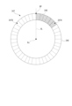
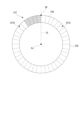
- the ratio display section 347 displays the adjusted ratio under the control of the display control section 58 .
- the ratio display section 347 is composed of a plurality of light emitting elements 348 arranged along the rotation direction of the dial 346 .
- the ratio display portion 347 includes a first region 347A that is half a clockwise region from the base point BP provided in the circumferential direction of the dial 346, and a second region 347B that is a half counterclockwise region from the base point BP. and
- the first area 347A is an area for displaying the post-adjustment ratio when the post-adjustment BPM is greater than the original BPM.
- the post-adjustment ratio is displayed by lighting the same number of light-emitting elements 348 from the base point BP. For example, when the post-adjustment ratio is 130%, the display control unit 58, as shown in FIG. The post-adjustment ratio is displayed on the ratio display section 347 by lighting the number of light emitting elements 348 corresponding to 30% from the base point BP.
- one of the clockwise first region 347A and the counterclockwise second region 347B displays the post-adjustment ratio centering on the base point BP, so that the user can intuitively see the post-adjustment ratio. I can grasp it.
- the luminescent color of the light emitting element 348 arranged in the first region 347A and the luminescent color of the light emitting element 348 arranged in the second region 347B may be different.
- the light-emitting elements 348 that are lit when the adjusted BPM is greater than the original BPM are lit in red among the warm colors
- the light-emitting elements 348 that are lit when the adjusted BPM is less than the original BPM are lit in cool colors. Of these, blue may be lit.
- the process of calculating the position of the base point BP on the rotated dial 346 can be omitted.
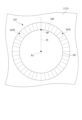
- FIG. 15 is a schematic diagram showing an acoustic control device 1A that is a modification of the acoustic control device 1.
- the playback speed operation section 34 is provided for each channel operation section 3 .
- one reproduction speed operation unit 34 may be provided for the entire sound control device, such as the sound control device 1A shown in FIG. 15, for example.
- the control unit 5 simultaneously adjusts the reproduction speeds of songs on all channels according to the operation on the reproduction speed operation unit 34 .
- the control unit 5 may increase or decrease the BPM during reproduction of music on all channels by the same value in accordance with the rotation state of one reproduction speed operation unit 34. may be increased or decreased at the same rate.
- the amount of change in the reproduction speed of the music for each unit rotation angle may be changed.
- the dials 341 and 346 are rotated by a predetermined angle in one of clockwise and counterclockwise directions, and then rotated by a predetermined angle in the other direction, the control unit 5 is further rotated in one direction.
- the control unit 5 determines whether the dials 341 and 346 are rotated toward the housing 2 without being pressed down, or when the dials 341 and 346 are rotated toward the housing 2 while being pressed down. It is also possible to change the amount of change in BPM of music for each unit rotation angle of 341 and 346 and the amount of change in playback speed of music for each unit rotation angle.
- the control unit 5 sets the amount of change in the BPM of the song for each unit rotation angle of the dials 341, 346 as the first amount of change while the rotation speed of the dials 341, 346 is less than the predetermined speed, While the rotation speed of the dials 341, 346 is equal to or higher than the predetermined speed, the BPM of the music for each unit rotation angle of the dials 341, 346 is set to the second amount of change larger than the first amount of change.
- the second amount of change may be a smaller amount of change than the first amount of change.
- the control unit 5 increases the BPM and playback speed of the music, and rotates the dials 341 and 346 in the first rotation direction. is rotated in the opposite direction, counterclockwise, to decrease the BPM and playback speed of the song.
- the present invention is not limited to this, and the control unit 5 increases the BPM and playback speed of the music when the dials 341 and 346 are rotated counterclockwise, and increases the music playback speed when the dials 341 and 346 are rotated clockwise. BPM and playback speed may be reduced.
- the control unit 5 may be configured to increase or decrease the BPM and playback speed of the music only when the dials 341 and 346 are rotated in one of the clockwise and counterclockwise directions.
- the display unit 344 displays, as information about the music reproduction speed adjusted by the control unit 5, information indicating the ratio of the BPM of the music after the reproduction speed adjustment to the BPM specific to the music.
- the display unit 344 is not limited to this and may display other information.
- the display unit 344 may display the original BPM and the adjusted BPM.
- the brightness of the figures FG1 and FG2 is assumed to differ according to the ratio of the BPM after adjustment to the original BPM (ratio after adjustment).
- the brightness of the graphics FG1 and FG2 may be constant regardless of the post-adjustment ratio.
- the colors and blinking periods of the graphics FG1 and FG2 may be constant regardless of the post-adjustment ratio.
- graphics may be displayed by combining at least two of brightness, color, and blinking cycle.
- the post-adjustment ratio range indicated by the first reference line FG31 that defines the slide range in which the slide operator FG33 can slide is different according to the post-adjustment ratio.
- the range of post-adjustment ratio indicated by the slide range is not limited to this, and may be constant.
- the acoustic control device 1, 1A is provided with the display section 344 that displays the graphics FG1, FG2, FG3, and the like.
- the display unit 344 may not necessarily be provided.
- an external device connected to the sound control device may have a display section for displaying graphics or the like.
- the light-emitting element 348 that constitutes the ratio display portion 347 is provided over one circumference of the dial 346 in the rotation direction of the dial 346 .
- the range in which the light emitting element 348 is provided is not limited to this, and can be changed as appropriate. The same applies when the light-emitting element 348 is provided around the dial 346 .
- the display modes of the display section 344 provided in each channel operation section 3 include direct display mode, ratio display mode, figure display mode, and slider display mode.
- the acoustic control device does not necessarily have to be configured to be able to set all of these display modes.
- the sound control device may have at least one of the graphic display mode and the slider display mode as switchable display modes.
- An acoustic control device capable of adjusting the playback speed of a song, comprising: a rotatably provided dial for accepting an operation for adjusting the playback speed of the song; and a control unit that changes an amount of change in the reproduction speed of the music piece for each unit rotation angle.
- a control unit that changes an amount of change in the reproduction speed of the music piece for each unit rotation angle.
- the control unit adjusts the amount of change in the BPM of the song for each unit rotation angle of the dial while the rotation speed of the dial is less than a predetermined speed. 1 change amount, and while the rotation speed of the dial is equal to or higher than the predetermined speed, the change amount of the BPM of the song for each unit rotation angle of the dial may be set as a second change amount larger than the first change amount. good. According to such a configuration, the amount of change in the BPM of the song for each unit rotation angle of the dial can be switched between the first amount of change and the second amount of change according to the rotational speed of the dial.
- a housing having the dial rotatably provided on a first surface is provided, and the first rotation direction is a clock It may be in a circular direction.
- the dial is operated clockwise to increase the numerical value of a predetermined index, and the dial is operated counterclockwise to decrease the numerical value.
- the playback speed of music can be increased by rotating the dial clockwise, and the playback speed of music can be decreased by rotating the dial counterclockwise. can be done. Therefore, it is possible for the user to easily grasp the operation direction of the dial when increasing or decreasing the reproduction speed of the music, so that it is possible to easily perform the adjustment operation of the reproduction speed of the music.
- the display unit displays, as information about the reproduction speed of the music piece adjusted by the control unit, Information indicating the rate of BPM may be displayed. According to such a configuration, the user can intuitively grasp how much the playback speed specific to the music has been adjusted. Therefore, it is possible to easily adjust the playback speed of the music.
Landscapes
- Physics & Mathematics (AREA)
- Engineering & Computer Science (AREA)
- Acoustics & Sound (AREA)
- Signal Processing (AREA)
- Electrophonic Musical Instruments (AREA)
Priority Applications (2)
| Application Number | Priority Date | Filing Date | Title |
|---|---|---|---|
| PCT/JP2021/037740 WO2023062720A1 (ja) | 2021-10-12 | 2021-10-12 | 音響制御装置 |
| JP2023553795A JP7724871B2 (ja) | 2021-10-12 | 2021-10-12 | 音響制御装置 |
Applications Claiming Priority (1)
| Application Number | Priority Date | Filing Date | Title |
|---|---|---|---|
| PCT/JP2021/037740 WO2023062720A1 (ja) | 2021-10-12 | 2021-10-12 | 音響制御装置 |
Publications (1)
| Publication Number | Publication Date |
|---|---|
| WO2023062720A1 true WO2023062720A1 (ja) | 2023-04-20 |
Family
ID=85988484
Family Applications (1)
| Application Number | Title | Priority Date | Filing Date |
|---|---|---|---|
| PCT/JP2021/037740 Ceased WO2023062720A1 (ja) | 2021-10-12 | 2021-10-12 | 音響制御装置 |
Country Status (2)
| Country | Link |
|---|---|
| JP (1) | JP7724871B2 (https=) |
| WO (1) | WO2023062720A1 (https=) |
Citations (3)
| Publication number | Priority date | Publication date | Assignee | Title |
|---|---|---|---|---|
| JPH05158475A (ja) * | 1991-12-10 | 1993-06-25 | Casio Comput Co Ltd | 自動演奏装置 |
| WO2006104109A1 (ja) * | 2005-03-28 | 2006-10-05 | Pioneer Corporation | 情報再生装置及び方法、dj機器、並びにコンピュータプログラム |
| JP2016058123A (ja) * | 2014-09-10 | 2016-04-21 | Pioneer DJ株式会社 | 再生制御装置、再生制御装置の制御方法およびプログラム |
Family Cites Families (7)
| Publication number | Priority date | Publication date | Assignee | Title |
|---|---|---|---|---|
| JPS62265819A (ja) * | 1986-05-13 | 1987-11-18 | Sony Corp | 回転ダイヤル回路 |
| JPS63128417A (ja) * | 1986-11-19 | 1988-06-01 | Toshiba Corp | 画像処理装置に於る外部入力手段の制御装置 |
| JPH11272378A (ja) * | 1998-03-19 | 1999-10-08 | Poseidon Technical Systems:Kk | 入力装置及び該入力操作検知方法 |
| JP2005013576A (ja) * | 2003-06-27 | 2005-01-20 | Toshiba Corp | X線ct装置 |
| JP2009296305A (ja) * | 2008-06-05 | 2009-12-17 | Sony Corp | 操作装置、映像再生装置、操作情報出力方法 |
| JP6009447B2 (ja) * | 2011-08-26 | 2016-10-19 | Pioneer DJ株式会社 | 表示装置、表示方法、およびプログラム |
| US11386877B2 (en) * | 2017-12-29 | 2022-07-12 | Alphatheta Corporation | Audio equipment and program for audio equipment |
-
2021
- 2021-10-12 WO PCT/JP2021/037740 patent/WO2023062720A1/ja not_active Ceased
- 2021-10-12 JP JP2023553795A patent/JP7724871B2/ja active Active
Patent Citations (3)
| Publication number | Priority date | Publication date | Assignee | Title |
|---|---|---|---|---|
| JPH05158475A (ja) * | 1991-12-10 | 1993-06-25 | Casio Comput Co Ltd | 自動演奏装置 |
| WO2006104109A1 (ja) * | 2005-03-28 | 2006-10-05 | Pioneer Corporation | 情報再生装置及び方法、dj機器、並びにコンピュータプログラム |
| JP2016058123A (ja) * | 2014-09-10 | 2016-04-21 | Pioneer DJ株式会社 | 再生制御装置、再生制御装置の制御方法およびプログラム |
Also Published As
| Publication number | Publication date |
|---|---|
| JP7724871B2 (ja) | 2025-08-18 |
| JPWO2023062720A1 (https=) | 2023-04-20 |
Similar Documents
| Publication | Publication Date | Title |
|---|---|---|
| US7019788B2 (en) | Video mixer apparatus | |
| US20150078584A1 (en) | Live Sound Mixer User Interface | |
| US20100103321A1 (en) | Av processing apparatus and program | |
| US20200335075A1 (en) | Acoustic apparatus | |
| JP5194985B2 (ja) | 制御装置 | |
| JP3823631B2 (ja) | ディジタルミキサー装置 | |
| WO2023062720A1 (ja) | 音響制御装置 | |
| JP7724870B2 (ja) | 音響制御装置 | |
| EP4292682B1 (en) | Mixing device and mixing method | |
| JP2012189694A (ja) | 電子楽器 | |
| JP3896963B2 (ja) | 演奏教習装置および演奏教習プログラム | |
| US20230032630A1 (en) | Remote Control of Stringed Electric Instruments | |
| JP4748215B2 (ja) | サウンド設定装置及びサウンド設定方法 | |
| JP5028738B2 (ja) | 音響信号処理装置及びプログラム | |
| JP7498784B2 (ja) | 音響装置 | |
| JP3935010B2 (ja) | 楽音制御装置 | |
| JP6455270B2 (ja) | 電子音楽装置 | |
| JP2004207826A (ja) | ミキシングシステムの制御方法、ミキシングシステムの制御装置およびプログラム | |
| JP4967235B2 (ja) | ミキサ装置における画面照度調整装置及びプログラム | |
| US11188186B2 (en) | Part display apparatus, electronic music apparatus, and part display method | |
| JP2020048178A (ja) | 音信号処理装置、音信号処理方法およびプログラム | |
| WO2007125990A1 (ja) | スライド操作子、情報処理装置及び方法、並びにコンピュータプログラム | |
| WO2024241583A1 (ja) | 音響装置、音響装置の制御方法、及びプログラム | |
| JPH01151810A (ja) | イコライザ装置 | |
| JP2015165262A (ja) | 入力ソース選択装置およびその制御プログラム |
Legal Events
| Date | Code | Title | Description |
|---|---|---|---|
| 121 | Ep: the epo has been informed by wipo that ep was designated in this application |
Ref document number: 21960579 Country of ref document: EP Kind code of ref document: A1 |
|
| WWE | Wipo information: entry into national phase |
Ref document number: 2023553795 Country of ref document: JP |
|
| NENP | Non-entry into the national phase |
Ref country code: DE |
|
| 122 | Ep: pct application non-entry in european phase |
Ref document number: 21960579 Country of ref document: EP Kind code of ref document: A1 |