WO2023053922A1 - 助手席用エアバッグ装置 - Google Patents
助手席用エアバッグ装置 Download PDFInfo
- Publication number
- WO2023053922A1 WO2023053922A1 PCT/JP2022/034083 JP2022034083W WO2023053922A1 WO 2023053922 A1 WO2023053922 A1 WO 2023053922A1 JP 2022034083 W JP2022034083 W JP 2022034083W WO 2023053922 A1 WO2023053922 A1 WO 2023053922A1
- Authority
- WO
- WIPO (PCT)
- Prior art keywords
- chamber
- sub
- main chamber
- airbag device
- airbag
- Prior art date
- Legal status (The legal status is an assumption and is not a legal conclusion. Google has not performed a legal analysis and makes no representation as to the accuracy of the status listed.)
- Ceased
Links
Images


Classifications
-
- B—PERFORMING OPERATIONS; TRANSPORTING
- B60—VEHICLES IN GENERAL
- B60R—VEHICLES, VEHICLE FITTINGS, OR VEHICLE PARTS, NOT OTHERWISE PROVIDED FOR
- B60R21/00—Arrangements or fittings on vehicles for protecting or preventing injuries to occupants or pedestrians in case of accidents or other traffic risks
- B60R21/02—Occupant safety arrangements or fittings, e.g. crash pads
- B60R21/16—Inflatable occupant restraints or confinements designed to inflate upon impact or impending impact, e.g. air bags
- B60R21/23—Inflatable members
- B60R21/231—Inflatable members characterised by their shape, construction or spatial configuration
- B60R21/233—Inflatable members characterised by their shape, construction or spatial configuration comprising a plurality of individual compartments; comprising two or more bag-like members, one within the other
-
- B—PERFORMING OPERATIONS; TRANSPORTING
- B60—VEHICLES IN GENERAL
- B60R—VEHICLES, VEHICLE FITTINGS, OR VEHICLE PARTS, NOT OTHERWISE PROVIDED FOR
- B60R21/00—Arrangements or fittings on vehicles for protecting or preventing injuries to occupants or pedestrians in case of accidents or other traffic risks
- B60R21/02—Occupant safety arrangements or fittings, e.g. crash pads
- B60R21/16—Inflatable occupant restraints or confinements designed to inflate upon impact or impending impact, e.g. air bags
- B60R21/20—Arrangements for storing inflatable members in their non-use or deflated condition; Arrangement or mounting of air bag modules or components
- B60R21/205—Arrangements for storing inflatable members in their non-use or deflated condition; Arrangement or mounting of air bag modules or components in dashboards
-
- B—PERFORMING OPERATIONS; TRANSPORTING
- B60—VEHICLES IN GENERAL
- B60R—VEHICLES, VEHICLE FITTINGS, OR VEHICLE PARTS, NOT OTHERWISE PROVIDED FOR
- B60R21/00—Arrangements or fittings on vehicles for protecting or preventing injuries to occupants or pedestrians in case of accidents or other traffic risks
- B60R21/02—Occupant safety arrangements or fittings, e.g. crash pads
- B60R21/16—Inflatable occupant restraints or confinements designed to inflate upon impact or impending impact, e.g. air bags
- B60R21/23—Inflatable members
- B60R21/231—Inflatable members characterised by their shape, construction or spatial configuration
-
- B—PERFORMING OPERATIONS; TRANSPORTING
- B60—VEHICLES IN GENERAL
- B60R—VEHICLES, VEHICLE FITTINGS, OR VEHICLE PARTS, NOT OTHERWISE PROVIDED FOR
- B60R21/00—Arrangements or fittings on vehicles for protecting or preventing injuries to occupants or pedestrians in case of accidents or other traffic risks
- B60R21/02—Occupant safety arrangements or fittings, e.g. crash pads
- B60R21/16—Inflatable occupant restraints or confinements designed to inflate upon impact or impending impact, e.g. air bags
- B60R21/23—Inflatable members
- B60R21/239—Inflatable members characterised by their venting means
-
- B—PERFORMING OPERATIONS; TRANSPORTING
- B60—VEHICLES IN GENERAL
- B60R—VEHICLES, VEHICLE FITTINGS, OR VEHICLE PARTS, NOT OTHERWISE PROVIDED FOR
- B60R21/00—Arrangements or fittings on vehicles for protecting or preventing injuries to occupants or pedestrians in case of accidents or other traffic risks
- B60R2021/0002—Type of accident
- B60R2021/0009—Oblique collision
-
- B—PERFORMING OPERATIONS; TRANSPORTING
- B60—VEHICLES IN GENERAL
- B60R—VEHICLES, VEHICLE FITTINGS, OR VEHICLE PARTS, NOT OTHERWISE PROVIDED FOR
- B60R21/00—Arrangements or fittings on vehicles for protecting or preventing injuries to occupants or pedestrians in case of accidents or other traffic risks
- B60R2021/003—Arrangements or fittings on vehicles for protecting or preventing injuries to occupants or pedestrians in case of accidents or other traffic risks characterised by occupant or pedestian
- B60R2021/0039—Body parts of the occupant or pedestrian affected by the accident
- B60R2021/0048—Head
-
- B—PERFORMING OPERATIONS; TRANSPORTING
- B60—VEHICLES IN GENERAL
- B60R—VEHICLES, VEHICLE FITTINGS, OR VEHICLE PARTS, NOT OTHERWISE PROVIDED FOR
- B60R21/00—Arrangements or fittings on vehicles for protecting or preventing injuries to occupants or pedestrians in case of accidents or other traffic risks
- B60R21/02—Occupant safety arrangements or fittings, e.g. crash pads
- B60R21/16—Inflatable occupant restraints or confinements designed to inflate upon impact or impending impact, e.g. air bags
- B60R21/23—Inflatable members
- B60R21/231—Inflatable members characterised by their shape, construction or spatial configuration
- B60R2021/23107—Inflatable members characterised by their shape, construction or spatial configuration the bag being integrated in a multi-bag system
-
- B—PERFORMING OPERATIONS; TRANSPORTING
- B60—VEHICLES IN GENERAL
- B60R—VEHICLES, VEHICLE FITTINGS, OR VEHICLE PARTS, NOT OTHERWISE PROVIDED FOR
- B60R21/00—Arrangements or fittings on vehicles for protecting or preventing injuries to occupants or pedestrians in case of accidents or other traffic risks
- B60R21/02—Occupant safety arrangements or fittings, e.g. crash pads
- B60R21/16—Inflatable occupant restraints or confinements designed to inflate upon impact or impending impact, e.g. air bags
- B60R21/23—Inflatable members
- B60R21/231—Inflatable members characterised by their shape, construction or spatial configuration
- B60R21/233—Inflatable members characterised by their shape, construction or spatial configuration comprising a plurality of individual compartments; comprising two or more bag-like members, one within the other
- B60R2021/23324—Inner walls crating separate compartments, e.g. communicating with vents
-
- B—PERFORMING OPERATIONS; TRANSPORTING
- B60—VEHICLES IN GENERAL
- B60R—VEHICLES, VEHICLE FITTINGS, OR VEHICLE PARTS, NOT OTHERWISE PROVIDED FOR
- B60R21/00—Arrangements or fittings on vehicles for protecting or preventing injuries to occupants or pedestrians in case of accidents or other traffic risks
- B60R21/02—Occupant safety arrangements or fittings, e.g. crash pads
- B60R21/16—Inflatable occupant restraints or confinements designed to inflate upon impact or impending impact, e.g. air bags
- B60R21/23—Inflatable members
- B60R21/239—Inflatable members characterised by their venting means
- B60R2021/2395—Inflatable members characterised by their venting means comprising means to control the venting
Definitions
- the present invention relates to a passenger airbag device that protects an occupant sitting in the passenger seat of a vehicle.
- Airbags include, for example, so-called driver airbags that inflate from near the center of the steering wheel of an automobile to protect the driver, and passenger airbags that inflate from the instrument panel to protect the occupants in the front passenger seat. , and curtain airbags that deploy downward inside the vehicle window to protect occupants in the event of a vehicle lateral impact, rollover, or rollover accident.
- driver airbags that inflate from near the center of the steering wheel of an automobile to protect the driver
- passenger airbags that inflate from the instrument panel to protect the occupants in the front passenger seat.
- curtain airbags that deploy downward inside the vehicle window to protect occupants in the event of a vehicle lateral impact, rollover, or rollover accident.
- There are various forms such as a side airbag that deploys.
- the present invention relates to an airbag device for passenger's seat.
- the occupant may enter the deployed airbag at an irregular position and angle, and the occupant's head may not be properly protected. be.
- the head of the occupant in the front passenger seat comes into contact with a position that is displaced from the center of the airbag.
- a phenomenon called "bottoming out” will occur. That is, there is a possibility that a situation may occur in which it is difficult to properly restrain the head of the occupant.
- the present invention has been made in view of the above circumstances, and an object of the present invention is to provide an airbag device capable of appropriately restraining the head of an occupant sitting in the front passenger seat of a vehicle.
- the present invention provides an airbag device that is housed in an instrument panel of a vehicle and protects an occupant in a front passenger seat, comprising: an inflator that generates inflation gas; gas released from the inflator; and an airbag that inflates and deploys toward the occupant side.
- the airbag has a main chamber that communicates with the inflator and is located in a region including the front of the normally seated occupant when deployed, and a sub-chamber that is connected to the side of the main chamber.
- An inner vent through which gas flows is formed at the boundary between the main chamber and the sub-chamber.
- a check valve capable of opening and closing the inner vent is provided.
- the “instrument panel” is the part located in front of the front seats of a vehicle and located below the windshield (windshield), and is generally molded from resin and is called the dashboard.
- the airbag device can be accommodated inside other structural parts in the cabin as well as inside the instrument panel.
- side is a concept that includes one or both of the left and right sides of the main chamber.
- the "boundary part” is the part where the main chamber and the sub-chamber are in contact with each other as a region, and not only when the entire side surfaces of the chambers are connected by sewing etc. at the boundary part, but also includes at least the periphery of the inner vent. It also includes the state of connecting certain regions.
- front means the front of the vehicle (in the direction of travel)
- rear means the rear of the vehicle (opposite to the direction of travel)
- right means The right side as seen in the direction of travel, "left” as viewed in the direction of travel, and the "vehicle width direction” as the left-right direction.
- the inflation gas generated from the inflator flows into the main chamber of the airbag and then passes through the inner vent to reach the sub-chamber, whereupon the airbag is inflated.
- the gas pressure in the sub-chamber rises and the check valve closes the inner vent to maintain the pressure in the sub-chamber. It is possible to appropriately restrain the occupant who has entered the sub-chamber.
- the sub-chamber can be provided on the center side (driver's seat side) of the vehicle with respect to the main chamber. As a result, it is possible to reliably avoid a situation in which an occupant sitting in the front passenger seat comes into contact with the center console, instrument panel, driver, etc. due to the impact of the collision.
- the check valve can be composed of a flexible cloth-like member arranged to cover the inner vent.
- the cloth-like member the same fabric as that forming the airbag can be used.
- the volume of the sub-chamber smaller than the volume of the main chamber. This is because the occupant is reliably restrained by the main chamber having a large volume in the event of a head-on collision or the like.
- the main chamber and the sub-chamber can be molded as independent and separate bags.
- the inner vent is constituted by an opening formed in both chambers at a portion where the main chamber and the sub-chamber are in contact with each other.
- the main chamber and the sub-chamber can be formed, and the inner vent can be formed in the partition panel.
- the sub-chamber can be formed by a base fabric whose perimeter is connected to the side surface of the main chamber. At this time, the inner vent is formed on the side surface of the main chamber.
- the main chamber preferably has a vent hole for exhausting gas to the outside.
- the internal pressure of the sub-chamber rises when an occupant touches the sub-chamber, but the internal pressure of the main chamber gradually decreases. will decrease. For this reason, the sub-chamber, whose internal pressure is maintained, tends to move toward or tilt toward the main chamber, which has become flexible due to the exhaust of the gas. As a result, the occupant's head can be reliably restrained without the sub-chamber escaping outward (to the side opposite to the main chamber).
- the sub-chamber can be configured to have a substantially triangular shape when the deployed state is observed from above.
- substantially triangular is not limited to a strict triangle, but also includes a shape having three sides, with slightly rounded or slightly chamfered corners.
- the triangular shape has a first side facing the occupant, a second side positioned at the boundary with the main chamber, and a third side forming a side portion of the airbag. be able to.
- the force received by the sub-chamber when an occupant enters the plane corresponding to the first side of the sub-chamber (occupant side) is can be absorbed by
- the length of the first side can be formed to be shorter than the length of the second side.
- the lateral width of the sub-chamber when deployed is shorter than the longitudinal depth thereof.
- the surface forming the first side of the sub-chamber and the surface of the main chamber facing the occupant can be configured to form substantially the same surface.
- the front end of the sub-chamber can be configured to be located rearward from the front end of the main chamber.
- the sub-chamber may be configured to be connected only to one side of the main chamber.
- the sub-chamber may be configured to be connected to a side portion of the main chamber on the vehicle interior side.
- the sub-chamber can be connected to the side of the main chamber on the exterior side (window side).
- subchambers can be provided on both left and right sides of the main chamber.
- the occupant's head can be appropriately restrained regardless of the direction (offset angle) in which the vehicle collides.
- FIG. 1 is a side view showing the deployed state of an airbag according to the present invention.
- FIG. 2 shows the deployed state of the airbag according to the first embodiment of the present invention, and corresponds to a cross section taken along the A1-A1 direction in FIG.
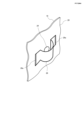
- FIG. 3 is a perspective view showing an enlarged main part of FIG. 2.
- FIG. 4 schematically shows the deployed state of the airbag according to the present invention, and is an explanatory view showing the dimensions (shape, dimensional ratio, etc.) of the airbag.
- FIG. 5 is a cross-sectional view (overhead view) showing the deployed state of the airbag according to the first embodiment of the present invention, showing the state in which the occupant has entered the sub-chamber.
- FIG. 1 is a side view showing the deployed state of an airbag according to the present invention.
- FIG. 2 shows the deployed state of the airbag according to the first embodiment of the present invention, and corresponds to a cross section taken along the A1-A1 direction in FIG.
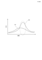
- FIG. 6 is a graph showing pressure fluctuations of an airbag according to the present invention.
- FIG. 7 shows the deployed state of the airbag according to the second embodiment of the present invention, and corresponds to the cross section taken along the A1-A1 direction in FIG.
- FIG. 8 shows the deployed state of the airbag according to the third embodiment of the present invention, and corresponds to the cross section along the A1-A1 direction in FIG.
- FIG. 9 shows the deployed state of the airbag according to the fourth embodiment of the present invention, and corresponds to the cross section along the A1-A1 direction in FIG.
- FIG. 10 shows the deployed state of the airbag according to the fifth embodiment of the present invention, and corresponds to the cross section along the A1-A1 direction in FIG.
- FIG. 1 is a side view showing an unfolded state of an airbag 14 of a passenger-side airbag device according to the first embodiment of the present invention.
- FIG. 2 is a cross-sectional view in the direction of A1-A1 in FIG. 1, showing the deployed state of the airbag 14.
- FIG. 3 is a perspective view showing an enlarged main portion (around the inner vent) of FIG. 2 .
- the airbag device is housed in an instrument panel 10 of a vehicle and protects an occupant P in a front passenger seat.
- An airbag 14 that inflates and deploys toward the occupant P side is provided.
- the airbag 14 is connected to a main chamber 18 that communicates with the inflator 12 and deploys in front of the normally seated occupant P, and a side portion (right side portion in this embodiment) of the main chamber 18 on the vehicle center side. and a subchamber 20 .
- An inner vent 24 through which gas flows is formed at the boundary between the main chamber 18 and the sub-chamber 20, and a check valve 26 capable of opening and closing the inner vent 24 is provided.
- the main chamber 18 and the sub-chamber 20 are connected by sewing at the boundary.
- the sewing range includes at least the periphery of the inner vent 24, but other regions can also be sewn.
- vent holes 22 are formed in the left and right sides of the main chamber 18 for discharging the gas inside the main chamber 18 .
- the main chamber 18 and the subchamber 20 are molded as independent and separate bags.
- the inner vent 24 is formed by openings formed in both the main chamber 18 and the sub-chamber 20 at the contact portion.
- the check valve 26 is a flexible cloth-like member arranged to cover the inner vent 24, and can be made of the same fabric that forms the airbag 14, for example.
- An end portion 26a of the check valve 26 is connected to the inner surface of the subchamber 20 by sewing.
- the check valve 26 becomes convex toward the inside of the sub-chamber 20 by the gas flowing from the main chamber 18 to the sub-chamber 20 side, so that the inner vent 24 is opened.
- the check valve 26 is in close contact with the inner surface of the sub-chamber 20 to close the inner vent 24 .
- the volume of the subchamber 20 is set smaller than that of the main chamber 18 .
- the volume of subchamber 20 can be 10-20% of the volume of main chamber 18 .
- FIG. 4 schematically shows the deployment state of the airbag according to the present invention, and is an explanatory diagram showing the dimensions (shape, dimensional ratio, etc.) of the airbag 14. As shown in FIG.
- the sub-chamber 20 is configured to have a substantially triangular shape when the deployed state is observed from above.
- substantially triangular is not limited to a strictly triangular shape, but also includes a shape having three sides, with slightly rounded or slightly chamfered corners.
- the triangular shape of the sub-chamber 20 when viewed from the top includes a first side a1 facing the occupant, a second side a2 located at the boundary with the main chamber 18, and an airbag 14. and a third side a3 forming part of the side portion (right side portion) on the vehicle center side.
- the main chamber 18 can absorb the force that the sub-chamber 20 receives.
- the length L1 of the first side a1 is shorter than the length L2 of the second side a2, and the lateral width (L1) of the subchamber 20 when deployed is shorter than the longitudinal depth.
- the surface forming the first side a1 of the sub-chamber 20 and the surface A1 of the main chamber 18 facing the occupant are configured to form substantially the same surface.
- front end 20F of the subchamber 20 is configured to be located rearward from the front end 18F of the main chamber 18.
- FIG. 5 is a cross-sectional view (overhead view) showing the unfolded state of the passenger airbag 14 according to the first embodiment of the present invention, showing the state in which the occupant P has entered the sub-chamber 20.
- FIG. 6 is a graph showing variations in internal pressure of the main chamber 18 and the sub-chamber 20, where 18A represents the internal pressure of the main chamber 18 and 20A represents the internal pressure of the sub-chamber 20. As shown in FIG.
- the inflation gas generated from the inflator 12 flows into the main chamber 18 of the airbag 14 and then into the sub-chamber 20 via the inner vent 24 .
- the check valve 26 provided inside the sub-chamber 20 is swollen toward the sub-chamber 20 by the pressure of the gas flowing from the main chamber 18 , and the gas flows into the sub-chamber 20 from the inner vent 24 . It will flow in quickly (see Figure 2).
- the sub-chamber 20 As described above, when the occupant P contacts the sub-chamber 20, the internal pressure of the sub-chamber 20 increases, but the internal pressure of the main chamber 18 gradually decreases. Therefore, the sub-chamber 20 with its internal pressure maintained tends to move or tilt toward the main chamber 18 which has become flexible due to the exhaust of the gas. As a result, the head of the occupant P can be reliably restrained without the sub-chamber 20 escaping to the outside (to the side opposite to the main chamber 18).
- FIG. 7 shows the deployed state of the airbag 114 according to the second embodiment of the present invention, and corresponds to the cross section along the A1-A1 direction in FIG.
- the main chamber 18 and the sub-chamber 20 constituting the airbag 14 are constructed as independent and separate bags.
- a main chamber 118 and a sub-chamber 120 are formed by providing a partition panel 130 inside the airbag (114).
- the partition panel 130 is provided with an inner vent 124 and a check valve 126 .
- the functions of the inner vent 124 and the check valve 126 are the same as in the first embodiment.
- Front and rear ends 130a of the partition panel 130 are connected to the inner surface of the airbag by sewing. Also, the end portion 126a of the check valve 126 is connected to the surface of the partition panel 130 on the sub-chamber 120 side by sewing.
- Vent holes 122 are formed at two locations on the outer surface of the main chamber 118 in the same manner as in the first embodiment.
- the partition panel 130 is provided inside the single airbag, the structure is simpler than in the first embodiment, and simplification of the manufacturing process is expected.
- FIG. 8 shows the deployed state of the airbag 214 according to the third embodiment of the present invention, and corresponds to the cross section along the A1-A1 direction in FIG.
- the main chamber 18 and the sub-chamber 20 constituting the airbag 14 are constructed as independent and separate bags.
- a sub-chamber 220 is formed by stitching a base fabric to the sides of 218 . That is, the sub-chamber 220 is formed by sewing the perimeter 220a of the base fabric for the sub-chamber to the side surface of the main chamber 218 .
- An inner vent 224 communicating with the sub-chamber 220 is formed in the main chamber 218 , and a check valve 226 is provided so as to cover the inner vent 224 .
- the basic functions of the inner vent 224 and the check valve 226 are the same as in the first embodiment.
- vent holes 222 are formed at two locations on the outer surface of the main chamber 218, as in the first embodiment.
- FIG. 9 shows the unfolded state of the airbag 314 according to the fourth embodiment of the invention, and corresponds to the cross section along the A1-A1 direction in FIG.
- the upper surface shape of the subchambers (20, 120, 220) was substantially triangular, but the subchamber 320 employed in this embodiment is substantially rectangular. It's becoming Configurations other than the shape of the sub-chamber are the same as those of the first embodiment, and redundant description will be omitted.
- Vent holes 322 are formed at two locations on the outer surface of the main chamber 318 in the same manner as in the first embodiment.
- the subchambers 20, 120, 220, 320 employed in the first to fourth embodiments described above are connected only to one side of the main chambers 18, 118, 218, 318, when the subchambers 20 , 120 , 220 , 320 are preferably connected to side portions of main chambers 18 , 118 , 218 , 318 on the interior side of the vehicle (vehicle center side: far side). This is because curtain airbags are usually deployed on the outside of the vehicle (vehicle door side: near side), so there is a high need for head protection on the inside of the vehicle where there is no curtain airbag.
- FIG. 10 shows the unfolded state of the airbag 414 according to the fifth embodiment of the invention, and corresponds to the cross section along the A1-A1 direction in FIG.
- the sub-chambers 20 are provided on one side of the main chamber 18 constituting the airbag 14. It has a structure in which the subchambers 420L and 420R are connected. Since other structures are basically the same as those of the first embodiment, redundant description will be omitted. Also, in the second to fourth embodiments, it is possible to employ a structure in which the sub-chambers are connected to the left and right sides of the main chamber as in the present embodiment.
- two vent holes 422 are formed on the outer surface of the main chamber 418 .
- Inner vents 424L and 424R are formed at portions where the main chamber 418 and the sub-chambers 420L and 420R are in contact with each other by openings formed in both chambers.
- Check valves 426L and 426R are provided to cover the inner vents 424L and 424R. The inner vents 424L, 424R are opened by causing the check valves 426L, 426R to project toward the interior of the subchambers 420L, 420R by the gas flowing from the main chamber 418 into the subchambers 420L, 420R. .
- the inflation gas generated from the inflator 12 flows into the main chamber 418 and then into the sub-chambers 426L and 426R via the inner vents 424L and 420R.
- the check valves 426L, 426R provided inside the subchambers 420L, 420R are in a state of convexly swelling toward the subchambers 420L, 420R due to the pressure of the gas flowing from the main chamber 418, and the inner vents 424L, 424L
- the gas quickly flows from 424R into the sub-chambers 420L and 420R.
- the internal pressures of the main chamber 418 and the sub-chamber 420R gradually decrease. Therefore, the sub-chamber 420L, whose internal pressure is maintained, tends to move or tilt toward the main chamber 418 and the sub-chamber 420R, which have become flexible due to the gas exhaust. As a result, the occupant's head can be reliably restrained without the sub-chamber 420L escaping outward (to the side opposite to the main chamber 418). When the occupant enters the sub-chamber 420R, the same behavior (left-right reverse) is exhibited.
- the sub-chambers 420L and 420R are arranged and formed symmetrically, but they may have different shapes, sizes, and arrangements on the left and right. For example, if the volume of the sub-chamber on the far side of the vehicle is increased and the volume on the near side is decreased, the occupant's head can be reliably protected by the larger sub-chamber on the far side. On the other hand, on the near side, the occupant's head can be reliably protected by the smaller sub-chamber and curtain airbag.
Landscapes
- Engineering & Computer Science (AREA)
- Mechanical Engineering (AREA)
- Air Bags (AREA)
Priority Applications (4)
| Application Number | Priority Date | Filing Date | Title |
|---|---|---|---|
| EP22875794.4A EP4410607A4 (en) | 2021-10-01 | 2022-09-12 | PASSENGER SEAT AIRBAG DEVICE |
| CN202280065134.4A CN117999198A (zh) | 2021-10-01 | 2022-09-12 | 副驾驶座用气囊装置 |
| US18/695,907 US12269414B2 (en) | 2021-10-01 | 2022-09-12 | Passenger seat airbag device |
| JP2023550529A JPWO2023053922A1 (https=) | 2021-10-01 | 2022-09-12 |
Applications Claiming Priority (2)
| Application Number | Priority Date | Filing Date | Title |
|---|---|---|---|
| JP2021163134 | 2021-10-01 | ||
| JP2021-163134 | 2021-10-01 |
Publications (1)
| Publication Number | Publication Date |
|---|---|
| WO2023053922A1 true WO2023053922A1 (ja) | 2023-04-06 |
Family
ID=85782416
Family Applications (1)
| Application Number | Title | Priority Date | Filing Date |
|---|---|---|---|
| PCT/JP2022/034083 Ceased WO2023053922A1 (ja) | 2021-10-01 | 2022-09-12 | 助手席用エアバッグ装置 |
Country Status (5)
| Country | Link |
|---|---|
| US (1) | US12269414B2 (https=) |
| EP (1) | EP4410607A4 (https=) |
| JP (1) | JPWO2023053922A1 (https=) |
| CN (1) | CN117999198A (https=) |
| WO (1) | WO2023053922A1 (https=) |
Families Citing this family (1)
| Publication number | Priority date | Publication date | Assignee | Title |
|---|---|---|---|---|
| US20260091755A1 (en) * | 2024-09-30 | 2026-04-02 | Hyundai Mobis Co., Ltd. | Passenger airbag |
Citations (5)
| Publication number | Priority date | Publication date | Assignee | Title |
|---|---|---|---|---|
| JP2007161201A (ja) * | 2005-12-16 | 2007-06-28 | Toyota Motor Corp | エアバッグ装置 |
| JP2016040160A (ja) * | 2014-08-12 | 2016-03-24 | 豊田合成株式会社 | 助手席用エアバッグ装置 |
| US20180251093A1 (en) * | 2017-03-01 | 2018-09-06 | Autoliv Asp, Inc. | Frontal airbag systems for oblique impact |
| JP2018167760A (ja) * | 2017-03-30 | 2018-11-01 | タカタ株式会社 | エアバッグ及びエアバッグ装置 |
| JP2020023307A (ja) * | 2018-07-30 | 2020-02-13 | オートリブ ディベロップメント エービー | エアバッグ |
Family Cites Families (14)
| Publication number | Priority date | Publication date | Assignee | Title |
|---|---|---|---|---|
| US4262931A (en) * | 1979-09-18 | 1981-04-21 | Ford Motor Company | Air bag restraint system |
| GB2472071A (en) * | 2009-07-23 | 2011-01-26 | Ford Global Tech Llc | An airbag assembly |
| DE102011054053B4 (de) * | 2011-09-29 | 2018-05-03 | Autoliv Development Ab | Airbaganordnung mit einem einen zentralen Gassackbereich und seitlich dazu aufblasbaren Seitengassackbereichen |
| US9381885B2 (en) * | 2013-03-01 | 2016-07-05 | Tk Holdings Inc. | Tether airbag control system |
| US9566937B1 (en) * | 2013-08-29 | 2017-02-14 | Tk Holdings Inc. | Passenger airbag |
| JP6536963B2 (ja) * | 2014-01-21 | 2019-07-03 | ジョイソン セイフティ システムズ アクイジション エルエルシー | 乗客側エアバッグ |
| US9580039B2 (en) * | 2014-04-22 | 2017-02-28 | Autoliv Asp, Inc. | Multi-chamber airbag with unidirectional vent |
| KR102216133B1 (ko) * | 2014-08-14 | 2021-02-16 | 현대모비스 주식회사 | 차량의 동승석 에어백 |
| US9187055B1 (en) * | 2014-12-02 | 2015-11-17 | Toyoda Gosei Co., Ltd. | Vehicle airbag |
| US9533652B1 (en) * | 2015-07-14 | 2017-01-03 | Autoliv Asp, Inc. | One-directional valve for multi-chamber airbags |
| US10293777B2 (en) * | 2016-08-26 | 2019-05-21 | Autoliv Asp, Inc. | Multi-cushion airbag assemblies for reducing rotational velocity of an occupant's head |
| US20190039557A1 (en) * | 2017-08-01 | 2019-02-07 | GM Global Technology Operations LLC | Airbag cushion with internal valve for secondary pressure chamber |
| JP2019137129A (ja) * | 2018-02-07 | 2019-08-22 | Joyson Safety Systems Japan株式会社 | エアバッグ及びエアバッグ装置 |
| CN110843718B (zh) * | 2018-07-30 | 2025-07-29 | 奥托立夫开发公司 | 安全气囊 |
-
2022
- 2022-09-12 JP JP2023550529A patent/JPWO2023053922A1/ja active Pending
- 2022-09-12 WO PCT/JP2022/034083 patent/WO2023053922A1/ja not_active Ceased
- 2022-09-12 CN CN202280065134.4A patent/CN117999198A/zh active Pending
- 2022-09-12 EP EP22875794.4A patent/EP4410607A4/en active Pending
- 2022-09-12 US US18/695,907 patent/US12269414B2/en active Active
Patent Citations (5)
| Publication number | Priority date | Publication date | Assignee | Title |
|---|---|---|---|---|
| JP2007161201A (ja) * | 2005-12-16 | 2007-06-28 | Toyota Motor Corp | エアバッグ装置 |
| JP2016040160A (ja) * | 2014-08-12 | 2016-03-24 | 豊田合成株式会社 | 助手席用エアバッグ装置 |
| US20180251093A1 (en) * | 2017-03-01 | 2018-09-06 | Autoliv Asp, Inc. | Frontal airbag systems for oblique impact |
| JP2018167760A (ja) * | 2017-03-30 | 2018-11-01 | タカタ株式会社 | エアバッグ及びエアバッグ装置 |
| JP2020023307A (ja) * | 2018-07-30 | 2020-02-13 | オートリブ ディベロップメント エービー | エアバッグ |
Non-Patent Citations (1)
| Title |
|---|
| See also references of EP4410607A4 * |
Also Published As
| Publication number | Publication date |
|---|---|
| EP4410607A4 (en) | 2025-10-01 |
| US12269414B2 (en) | 2025-04-08 |
| EP4410607A1 (en) | 2024-08-07 |
| CN117999198A (zh) | 2024-05-07 |
| JPWO2023053922A1 (https=) | 2023-04-06 |
| US20240409057A1 (en) | 2024-12-12 |
Similar Documents
| Publication | Publication Date | Title |
|---|---|---|
| JP7014877B2 (ja) | エアバッグ装置およびエアバッグ装置の製造方法 | |
| KR102614143B1 (ko) | 차량용 멀티 전방에어백 및 이를 이용한 에어백 전개시스템 | |
| JP5651788B2 (ja) | シートボルスタ室 | |
| EP4019345B1 (en) | Airbag device | |
| JP6939179B2 (ja) | エアバッグ及び乗員拘束装置 | |
| EP1937517B1 (en) | Air bag system with inflatable tubular inner structure | |
| CN114514149B (zh) | 用于装备有实用部件的车辆乘坐位置的可充气安全气囊组件 | |
| JP7100163B2 (ja) | サイドエアバッグ装置 | |
| CN110869248A (zh) | 乘员保护装置 | |
| KR101807660B1 (ko) | 자동차의 조수석 에어백 | |
| CN113715770A (zh) | 用于车辆的侧面安全气囊 | |
| JP7380500B2 (ja) | 車両の乗員保護装置 | |
| CN107054279B (zh) | 具有不对称可调参数的双腔室安全气囊及其制造方法 | |
| JP7416823B2 (ja) | サイドエアバッグアセンブリ | |
| WO2023053922A1 (ja) | 助手席用エアバッグ装置 | |
| KR101561470B1 (ko) | 무릎에어백의 폴딩방법 | |
| KR20230129856A (ko) | 자동차의 조수석 에어백 장치 | |
| KR20230055158A (ko) | 차량의 루프 에어백 | |
| JPH1148889A (ja) | エアバッグ | |
| JP7762320B2 (ja) | エアバッグ装置 | |
| JP3500915B2 (ja) | 側面衝突用エアバッグ | |
| CN112124244A (zh) | 车辆用膝部安全气囊装置 | |
| JP5195734B2 (ja) | エアバッグ装置 | |
| JP3275771B2 (ja) | 側面衝突用エアバッグ | |
| CN114834385A (zh) | 膝部安全气囊装置 |
Legal Events
| Date | Code | Title | Description |
|---|---|---|---|
| 121 | Ep: the epo has been informed by wipo that ep was designated in this application |
Ref document number: 22875794 Country of ref document: EP Kind code of ref document: A1 |
|
| WWE | Wipo information: entry into national phase |
Ref document number: 2023550529 Country of ref document: JP |
|
| WWE | Wipo information: entry into national phase |
Ref document number: 202280065134.4 Country of ref document: CN |
|
| WWE | Wipo information: entry into national phase |
Ref document number: 18695907 Country of ref document: US |
|
| NENP | Non-entry into the national phase |
Ref country code: DE |
|
| ENP | Entry into the national phase |
Ref document number: 2022875794 Country of ref document: EP Effective date: 20240502 |
|
| WWG | Wipo information: grant in national office |
Ref document number: 18695907 Country of ref document: US |