WO2023053507A1 - ミシンの釜構造及びミシン - Google Patents
ミシンの釜構造及びミシン Download PDFInfo
- Publication number
- WO2023053507A1 WO2023053507A1 PCT/JP2022/011963 JP2022011963W WO2023053507A1 WO 2023053507 A1 WO2023053507 A1 WO 2023053507A1 JP 2022011963 W JP2022011963 W JP 2022011963W WO 2023053507 A1 WO2023053507 A1 WO 2023053507A1
- Authority
- WO
- WIPO (PCT)
- Prior art keywords
- needle
- thread
- bobbin
- sewing
- hook
- Prior art date
Links
- 238000009958 sewing Methods 0.000 title claims abstract description 331
- 230000033001 locomotion Effects 0.000 claims abstract description 191
- 239000000463 material Substances 0.000 claims description 63
- 230000007246 mechanism Effects 0.000 claims description 39
- 230000000149 penetrating effect Effects 0.000 claims description 2
- 230000015572 biosynthetic process Effects 0.000 abstract description 12
- 239000004744 fabric Substances 0.000 description 28
- 230000006870 function Effects 0.000 description 22
- 238000003825 pressing Methods 0.000 description 21
- 238000010586 diagram Methods 0.000 description 19
- 238000000034 method Methods 0.000 description 18
- 230000001105 regulatory effect Effects 0.000 description 17
- 230000008569 process Effects 0.000 description 13
- 230000004048 modification Effects 0.000 description 11
- 238000012986 modification Methods 0.000 description 11
- 238000004519 manufacturing process Methods 0.000 description 8
- 238000011144 upstream manufacturing Methods 0.000 description 6
- 230000009471 action Effects 0.000 description 5
- 238000005520 cutting process Methods 0.000 description 5
- 230000001276 controlling effect Effects 0.000 description 4
- 238000006073 displacement reaction Methods 0.000 description 4
- 238000003860 storage Methods 0.000 description 4
- 238000009966 trimming Methods 0.000 description 4
- 238000004891 communication Methods 0.000 description 3
- 238000004590 computer program Methods 0.000 description 3
- 230000007423 decrease Effects 0.000 description 3
- 230000001965 increasing effect Effects 0.000 description 3
- 230000009191 jumping Effects 0.000 description 3
- 238000004804 winding Methods 0.000 description 3
- 230000033228 biological regulation Effects 0.000 description 2
- 230000003247 decreasing effect Effects 0.000 description 2
- 230000002093 peripheral effect Effects 0.000 description 2
- 238000002360 preparation method Methods 0.000 description 2
- 230000002265 prevention Effects 0.000 description 2
- 230000004044 response Effects 0.000 description 2
- 230000000717 retained effect Effects 0.000 description 2
- 241001634884 Cochlicopa lubricella Species 0.000 description 1
- 208000003028 Stuttering Diseases 0.000 description 1
- 230000004913 activation Effects 0.000 description 1
- 230000002411 adverse Effects 0.000 description 1
- 238000010276 construction Methods 0.000 description 1
- 230000000694 effects Effects 0.000 description 1
- 230000003028 elevating effect Effects 0.000 description 1
- 230000001771 impaired effect Effects 0.000 description 1
- 230000006872 improvement Effects 0.000 description 1
- 230000002779 inactivation Effects 0.000 description 1
- 239000002184 metal Substances 0.000 description 1
- 231100000989 no adverse effect Toxicity 0.000 description 1
- 230000002829 reductive effect Effects 0.000 description 1
- 230000002441 reversible effect Effects 0.000 description 1
- 230000001360 synchronised effect Effects 0.000 description 1
- 230000007704 transition Effects 0.000 description 1
Images


Classifications
-
- D—TEXTILES; PAPER
- D05—SEWING; EMBROIDERING; TUFTING
- D05B—SEWING
- D05B57/00—Loop takers, e.g. loopers
- D05B57/08—Loop takers, e.g. loopers for lock-stitch sewing machines
- D05B57/10—Shuttles
- D05B57/14—Shuttles with rotary hooks
-
- D—TEXTILES; PAPER
- D05—SEWING; EMBROIDERING; TUFTING
- D05B—SEWING
- D05B57/00—Loop takers, e.g. loopers
- D05B57/08—Loop takers, e.g. loopers for lock-stitch sewing machines
- D05B57/10—Shuttles
- D05B57/14—Shuttles with rotary hooks
- D05B57/143—Vertical axis type
-
- D—TEXTILES; PAPER
- D05—SEWING; EMBROIDERING; TUFTING
- D05B—SEWING
- D05B57/00—Loop takers, e.g. loopers
- D05B57/26—Bobbin holders or casings; Bobbin holder or case guards; Bobbin discharge devices
Definitions
- the present invention relates to a hook structure of a sewing machine devised so as to avoid the occurrence of hitch stitches when forming seams on an object to be sewn, and further to a sewing machine provided with the hook structure.
- a sewing needle through which a needle thread is passed is vertically moved, and a hook containing a bobbin thread is rotated in synchronism with the vertical movement of the sewing needle, thereby entangling the needle thread with the bobbin thread and applying the needle thread to the work piece (work cloth). and a feed that forms stitches on the material to be sewn in any direction by displacing a frame (holding body) that holds the material to be sewn relative to the needle drop position.
- Sewing machines with mechanisms are known from the prior art. In such a sewing machine, by controlling the movement of the sewing material by the feed mechanism for each stitch, it is possible to form stitches of various lengths in various directions.
- a perfect stitch is a stitch formed by entwining the needle thread and the bobbin thread in a balanced state
- a hitch stitch is a seam formed by entwining only the needle thread with the bobbin thread in a spiral manner. be. It is known that there are two major factors in determining whether the formed seam is a perfect stitch or a hitch stitch. The first factor is the upper thread. When the needle threaded through the upper thread pierces the work cloth, the upper thread, which passes from the front of the eye of the sewing needle to the rear and is connected to the work cloth, forms the seam.
- a perfect stitch or a hitch stitch is formed depending on which direction, left-handed or right-handed, the sewing needle is entwined, depending on the movement direction of the work cloth (stitch forming direction). It is known that a hitch stitch is formed when the needle thread is entwined around the sewing needle in a right-handed direction.
- front refers to the left or right of the sewing machine when viewed from the front
- back refers to the direction when the sewing machine is viewed from above (that is, left winding is counterclockwise). direction, clockwise for right winding).
- the bobbin thread which is the path of the bobbin thread from the hook (bobbin thread) located below the throat plate to the work cloth above through the needle hole of the throat plate.
- a perfect stitch or a hitch stitch is formed depending on the relationship with the needle drop position of the needle. That is, the hitch stitch is formed when the path of the bobbin thread is on the right side with respect to the vertical flow line (needle drop position) of the sewing needle according to the movement direction of the work cloth when forming the seam (seam forming direction). It is known.
- the hitch stitch not only makes the seams look worse than the perfect stitch, but also has the problem of lowering the seam quality, such as the seams easily loosening. Therefore, conventionally, various methods for avoiding the occurrence of hitch stitches have been proposed. As an example, during the sewing operation for each stitch, it is determined whether the moving direction of the work cloth (stitch forming direction) is the perfect stitch forming direction or the hitch stitch forming direction. A method has been proposed in which the position of the needle thread or the bobbin thread relative to the needle drop position is displaced by means of an operating piece or the like.
- Patent Document 1 discloses an invention for avoiding the hitch stitch caused by the upper thread, and it was determined that the movement direction (seam forming direction) of the frame holding the work cloth is the hitch stitch forming direction caused by the upper thread.
- target position target needle drop position
- the target position is reached. This is intended to avoid the occurrence of hitch stitches caused by the needle thread by causing the needle thread, which is connected to the work cloth, to be twisted counterclockwise with respect to the sewing needle.
- Patent Document 2 discloses an invention for avoiding hitch stitching caused by a bobbin thread, in which notches are continuously provided on the back side of a needle hole formed in a throat plate to move a frame holding a work cloth.
- the direction switch formation direction
- the frame is moved without directly moving the frame to the target needle drop position (target position) for stitch formation. After detouring along the shape of the notch, the target position is reached.
- the notch has a tip portion extending from the left side to the right side, and the bobbin thread is moved around the frame so that the bobbin thread enters the tip portion of the notch portion from the left side, and the bobbin thread is moved to the tip portion of the notch portion.
- the needle is stopped at the tip of the notch so that the bobbin thread path passes through the left side of the needle drop position and is stopped on the far side (that is, the sewing needle drops to the right and front side of the bobbin thread path). to In this way, the sewing needle is caused to drop on the right side of the bobbin thread path that extends upward and connects to the work cloth, thereby avoiding the occurrence of hitch stitches caused by the bobbin thread. is intended.
- the upper thread loop captured by the blade point of the outer hook moves between the outer hook and the inner hook, is pulled up by the action of the thread take-up, and is entwined with the bobbin thread. to rise.
- the needle thread loop that ascends along the bobbin thread is caught by the protrusion (the peninsula portion) adjacent to the tip of the notch that locks the bobbin thread. can be. Then, upper thread breakage occurs. Further, since the bobbin thread enters the leading end of the notch and is retained, depending on the sewing direction of the next stitch, the bobbin thread remains retained at the notch, which is different from the normal bobbin thread path. There can also be a problem of stuttering.
- Patent Document 3 also discloses an invention that avoids hitch stitching caused by bobbin threads.
- the route of the bobbin thread from the hook to the needle hole of the throat plate is biased to the left side with respect to the vertical movement line (vertical movement locus) of the sewing needle, and the right side route is biased to the right side.
- a switching mechanism is provided for alternatively switching to and from, and the switching is performed by driving the air cylinder.
- the switching mechanism is operated before the tip of the sewing needle during its downward movement reaches the upper surface of the work cloth. to switch the route of the bobbin thread to the left route or the right route, thereby avoiding the occurrence of hitch stitches.
- it is necessary to provide an air cylinder driven switching mechanism there is a problem that the structure is complicated.
- Patent Document 4 discloses an invention for avoiding hitch stitching caused by needle thread and bobbin thread.
- a bobbin thread control means for controlling the relationship between the bobbin thread and the needle is provided, and each control means is controlled in accordance with the moving direction of the work cloth to avoid occurrence of hitch stitches.
- the needle bar rotation mechanism as the upper thread control means and the thread pulling mechanism as the lower thread control means each have a complicated structure, thus complicating the structure of the sewing machine.
- a multi-needle sewing machine having a single sewing head and a plurality of needle bars, such a complicated structure becomes a more serious problem.
- Patent Document 5 listed below discloses a sewing machine that can sew by rotating the sewing machine head and the shuttle housing portion. The sewing quality is improved by synchronizing each turning of the .
- a mechanism for rotating the sewing machine head and the hook housing and a means for synchronously controlling them must be provided, which complicates the structure.
- the structure shown in Patent Document 5 is suitable for sewing such as running stitches in which the stitches are sewn in a straight line in a fixed direction. , it is necessary to reverse the turning direction of the head and the hook accommodating part for each stitch, and the sewing direction also changes, so synchronous control is very difficult.
- Patent No. 2515400 Japanese Patent Application Laid-Open No. 6-343780 JP 2008-23261 JP 2012-213603 Patent No. 2540051
- a hook structure of a sewing machine that is suitable for avoiding the occurrence of hitch stitches caused by the bobbin thread.
- a hook structure of a sewing machine according to the present invention includes a bobbin case that rotatably accommodates a bobbin with a bobbin thread wound thereon, an inner hook that accommodates the bobbin case, and a needle that moves up and down around the inner hook.
- an outer hook that rotates in synchronism with the movement of the inner hook;
- a needle entry hole is provided in an upper front surface of the inner hook;
- a recess is formed at a position shifted in the direction, the recess is open on the front side and the top and bottom, and the back side forms a wall surface.
- a thread take-up member is provided for directing the hook toward the recess, and the bobbin thread let out from the bobbin in the bobbin case passes through the opening of the recess via the thread take-up member, It is characterized in that it is pulled out upward.
- the rotation direction of the outer hook is the direction in which the tip of the rotating outer hook catches (hooks) the needle thread loop in the hook. Normally, the direction of rotation of the outer hook is counterclockwise. ) faces left when viewed from the front. In this case, the concave portion of the inner hook is formed at a position shifted to the left side (toward the rotating direction of the outer hook) from the vertical movement line of the sewing needle.
- a holder (sewing frame or embroidery frame) holding a material to be sewn is arranged above a throat plate, and by moving the holder in any direction for each stitch, It is possible to form seams in any direction on the material to be sewn.
- a sewing needle through which an upper thread is passed is moved up and down, and a hook, which is arranged below the throat plate and stores the bobbin thread, is rotated in synchronism with the up and down movement of the sewing needle, thereby threading the bobbin thread.
- the needle thread is entwined with the needle thread, and the material to be sewn is sewn.
- the bobbin thread extending upward from the hook passes through the opening (needle hole) of the throat plate and is connected to the material to be sewn. , the bobbin thread coming out of the hook and connected to the material to be sewn from above also moves. Depending on the movement direction of the bobbin thread, the path of the bobbin thread with respect to the vertical movement line of the sewing needle also changes.
- the hook structure according to the present invention is designed so that the path of the bobbin thread extending from the hook to the needle hole of the throat plate does not come to the right side of the vertical movement line (vertical movement locus) of the sewing needle.
- the bobbin thread let out from the bobbin is directed toward the recess of the inner hook by the thread take-up member, passes through the recess, and heads toward the opening (needle hole) of the throat plate.
- the recessed portion is formed at a position offset from the needle drop hole in the rotational direction of the outer hook (that is, at a position on the left side with respect to the line of vertical movement of the sewing needle), so that the bobbin thread from the hook to the needle hole is displaced.
- the path is on the left side of the vertical flow line of the sewing needle.
- the second aspect of the present invention in addition to the configuration according to the first aspect, by providing a configuration for avoiding the occurrence of hitch stitches due to needle thread factors, what type of hitch stitches can occur.
- a sewing machine capable of avoiding a tangle and forming a perfect stitch over the entire range of sewing directions that is, a sewing machine capable of realizing an all-perfect stitch.
- a sewing machine has the hook structure, the needle thread through which the needle thread is threaded, and the needle thread is moved up and down.
- a sewing mechanism for entangling a needle thread and sewing a material to be sewn is provided.
- a feeding mechanism for forming a stitch in an arbitrary direction on the material to be sewn by displacing a holding body holding the material to be sewn relative to a needle drop position; and forming the next stitch.
- Determination means for determining whether the direction belongs to a predetermined region corresponding to a hitch stitch; detour control means for detouring the upper thread in the direction corresponding to the perfect stitch and then moving the holding body to the target position corresponding to the next stitch. Due to the detour movement of the holding body by such a detour control means, it is possible to avoid occurrence of hitch stitches caused by needle thread.
- FIG. 4 is a diagram listing the relationship between various seam formation directions and the quality of seams (perfect stitch and hitch stitch) formed according to each direction.
- 1 is a front view of a sewing machine according to an embodiment of the present invention
- FIG. 3 is an enlarged front view of one sewing machine head in the embodiment shown in FIG. 2
- FIG. FIG. 4 is a side cross-sectional view of the sewing machine head shown in FIG. 3
- FIG. 2 is an enlarged front view showing an embodiment of a presser device for pressing a sewn object
- It is a figure which shows the modification of the guide body in a pressing device, (a) is the perspective view seen from the bottom face side, (b) is a top view, (c) is a front view.
- FIG. 2 is a perspective cross-sectional view showing an embodiment of the throat plate structure
- FIG. 9 is an enlarged view showing the needle hole portion in FIG. 9, (a) is a plan view, (b) is a perspective view showing a cross section along line AA, and (c) is a perspective view of the main part illustrating the route of the bobbin thread. figure.
- the front view which shows one Example of a hook structure.
- FIG. 12 is a plan view of the pot structure of FIG. 11; Left side view and right side view of the pot structure of FIG. FIG. 12 is a perspective view showing an example of a bobbin case included in the hook structure of FIG. 11;
- FIG. 2 is a block diagram showing an example of a sewing machine control system;
- FIG. 11 is a diagram illustrating an area in which the frame is detoured to avoid hitch stitches caused by needle thread;
- FIG. 11 is a diagram illustrating a trajectory of detour movement of the frame;
- FIG. 4 is a cross-sectional plan view showing the relationship between the upper thread and the guide body of the presser device when the frame moves around; 4 is a flow chart showing an example of a computer program for executing sewing control consisting of all perfect stitches according to this embodiment.
- FIG. 11 is a diagram illustrating an area in which the frame is detoured to avoid hitch stitches caused by needle thread
- FIG. 11 is a diagram illustrating a trajectory of detour movement of the frame
- FIG. 10 is a diagram illustrating a mechanism for avoiding a hitch stitch caused by a bobbin thread by the hook structure according to the present embodiment
- FIG. 2 is an enlarged plan view
- FIG. 4 is a perspective view illustrating the function of the guide body of the presser device in detour movement control of the frame
- FIG. 4 is a perspective view illustrating the function of the guide body of the presser device in detour movement control of the frame
- FIG. 11 is a perspective view illustrating a mechanism for avoiding a hitch stitch by the throat plate structure shown in FIGS. 9 and 10
- FIG. 10 is a diagram showing an example of settings of frame detour control data
- FIG. 20 is a flow chart showing an extracted modification of the computer program shown in FIG. 19;
- FIG. 20 is a flow chart showing an extracted modification of the computer program shown in FIG. 19;
- FIG. 20 is a flow chart showing an extracted modification of the computer program shown in FIG. 19;
- FIG. 20 is a flow chart showing an extracted
- FIG. 1 is a diagram listing the relationship between various seam formation directions and the quality of seams (perfect stitch and hitch stitch) formed according to each direction. Note that the relationship between the direction of stitch formation and the quality of the seam formed varies depending on the orientation of the hook and the type of hook. It shows the relationship.
- the method of passing the needle thread through the eye of the sewing needle is such that the needle thread, which is fed downward from the needle thread bobbin, enters the eye from the front side of the sewing needle and exits rearward to cover the needle.
- a needle thread and a bobbin thread are entwined by cooperation between a sewing needle that moves up and down and a vertical hook that rotates fully counterclockwise to form stitches on a material to be sewn (work cloth).
- the reference point C located in the center of the figure indicates the current needle drop position (position of the needle hole in the throat plate of the sewing machine).
- Several arrows starting from the base point C exemplarily indicate the sewing direction from the base point C to the next needle drop point (that is, the direction in which the next stitch is formed).
- the sewing direction of each stitch can be arbitrarily set within a range of 360 degrees, and specifically depends on the sewing pattern.
- the direction of arrow P is 0 degrees, and the angles from 0 degrees to less than 360 degrees are scaled counterclockwise from there.
- the angle scale in FIG. 1 shall be followed.
- the directions of the arrows P and P' are the left and right directions of the sewing machine. do.
- the direction of the Y-axis perpendicular to the X-axis at the base point C is the front-rear direction of the sewing machine. (Y-).
- Y- the direction of movement of a holder (frame) holding an object to be sewn (work cloth) is opposite to the direction of stitches formed according to the movement of the holder (frame). relationship. For example, when forming a seam in the direction of arrow P (direction of 0 degrees), the holder (frame) moves in the opposite direction of arrow P' (direction of 180 degrees).
- FIG. 1 circled needle diagrams are drawn overlapping some arrows.
- This needle diagram is a diagram schematically showing a typical example of the relationship between the needle thread and the bobbin thread with respect to the sewing needle when a stitch in the direction corresponding to the arrow is formed, together with a picture of the needle hole, to aid understanding. be.
- This needle diagram shows the sewing needle in the downward movement just before entering the needle hole.
- the material to be sewn (work cloth) is omitted from the illustration.
- the total range of sewing directions can be divided into several regions ⁇ to ⁇ according to the quality of the seams formed according to the sewing directions.
- the area ⁇ is an area to which the sewing direction of the perfect stitch belongs, and is an area of about 270 degrees to 360 degrees (0 degrees) to about 85 degrees.
- the upper thread which passes from the eye of the sewing needle to the work cloth, is positioned to the left of the sewing needle.
- the stitches are perfect stitches because the needles enter the seam in the same condition.
- the region ( ⁇ to ⁇ ) except the outlined region ⁇ is the region where the hitch stitch occurs.
- the hatched area ⁇ is the area in which the sewing direction in which the hitch stitch occurs due to the needle thread belongs, and is the area of about 85 degrees to about 180 degrees.
- the upper thread which passes from the eye of the sewing needle to the work cloth, is positioned on the right side of the sewing needle.
- the stitches formed are hitch stitches because the needles enter the needle in a state where A dotted area ⁇ is an area in which a hitch stitch occurs due to both the upper thread and the bobbin thread, and is an area of about 180 degrees to about 210 degrees.
- the region ⁇ with the grid lines is the region in which the sewing direction in which the hitch stitch occurs due to the bobbin thread belongs, and is the region of about 210 degrees to about 270 degrees. As shown in the needle diagram drawn so as to overlap the arrow in this region ⁇ , the needle is sewn in a state where the bobbin thread leading from the hook to the work cloth is positioned on the right side of the sewing needle as the holding body (frame) moves. Because it falls off, the seams formed are hitch stitches.
- FIG. 2 is a front view of a sewing machine according to an embodiment of the present invention, showing an embodiment applied to a multi-head/multi-needle type embroidery sewing machine as an example.
- a sewing machine frame 1 positioned above a table 2 has a plurality of sewing heads H arranged in its longitudinal direction. Below each sewing machine head H, a hook base 4 supporting a hook 3 is provided corresponding to each sewing machine head H.
- a holding body 5 for holding a material to be sewn (work cloth) such as cloth in a stretched state.
- a mechanism (not shown) controls movement in the X and Y directions (front, rear, left, and right).
- the holder 5 is known as an embroidery frame or a work cloth holding frame or the like, and is hereinafter referred to as the frame 5 .
- an operation panel 6 for operating the sewing machine and various settings is provided.
- the operation panel 6 is, for example, a touch panel, and includes a display section for displaying various information and an input section for giving various instructions.
- This feed mechanism operates to form stitches in any direction on the sewing material by displacing the frame 5 holding the sewing material relative to the needle drop position. , itself is well known, and detailed description thereof will be omitted.
- FIG. 3 is an enlarged front view of the sewing machine head H
- FIG. 4 is its side view.
- a needle bar case 8 is slidably supported in the left-right direction on the front surface of a sewing machine arm 7 attached to the front surface of the sewing machine frame 1 .
- Needle bar case 8 supports a plurality of needle bars 9 so as to be able to move up and down, and thread take-up levers 10 corresponding to the respective needle bars 9 are rotatably arranged.
- Each needle bar 9 is arranged so that its axial direction extends in the up-down direction (vertical direction), and a sewing needle 11 is attached to the lower end of each needle bar.
- the needle thread T is passed through the eye 11a of the sewing needle 11 (see FIG.
- a slide shaft 12 extends through the needle bar case 8.
- the needle bar case 8 slides in the left-right direction.
- one of the plurality of needle bars 9 is selectively positioned at the operating position, and one needle bar 9 to be operated is selected.
- a main shaft 13 is passed through the sewing machine arm 7.
- the needle bar driving body 15 is rotated by a cam mechanism and a link 14 (not shown) in the sewing machine arm 7. 16 up and down.
- Needle bar driver 15 has a structure that engages with locking pin 17a of needle bar holder 17 fixed at a predetermined position on needle bar 9, and has a catching position for catching needle bar 9 and a non-catching position. can be switched to At the catch position, needle bar driver 15 engages locking pin 17a of needle bar clamp 17, as shown in FIG. At the non-catch position, needle bar driver 15 is disengaged from locking pin 17a of needle bar holder 17, and needle bar 9 is moved to the upper position ( top dead center).
- the needle bar driver 15 When the needle bar 9 (and the sewing needle 11) is actually moved up and down for sewing, the needle bar driver 15 is always set at the catch position.
- the control for temporarily stopping the needle bar 9 (and the sewing needle 11) at the top dead center during sewing is known as jump control.
- the needle bar driver 15 When performing such jump control, the needle bar driver 15 is temporarily set to the non-catching position.
- a known jump mechanism is provided in the sewing head H to perform such jump control. That is, this jump mechanism is a mechanism for holding the sewing needle 11 upward without lowering it when jump control is to be performed during the sewing operation.
- the jump mechanism includes a jump motor (not shown) provided on the sewing machine arm 7, and the needle bar driving body 15 is rotated by a predetermined angle around the base shaft 16 according to the driving of the jump motor. It is composed of a driving member (not shown) for setting the needle bar driving body 15 to the non-catching position, the tension spring 18 and the like.
- the needle bar 9 selected to the operating position moves up and down according to the up-and-down motion of the needle bar driving body 15 while being caught by the needle bar driving body 15 . While the needle bar 9 selected to the operating position moves up and down, the sewing needle 11 attached to the tip thereof is inserted through the needle hole 19a of the needle plate 19, and a well-known sewing operation is performed.
- the jump mechanism operates in response to the driving of the jump motor (not shown)
- the needle bar driving body 15 is set to the non-catching position, and the needle bar 9 is not caught by the needle bar driving body 15. It becomes a jump state and is held at the top dead center.
- Elevating rods 20 are provided in the needle bar case 8 behind the needle bars 9 so as to be movable up and down.
- the lift bar 20 is arranged such that its axial direction extends vertically (vertically), and a pressing device 21 is provided at the lower end of each.
- the presser device 21 presses the material to be sewn from above as the sewing needle 11 is lowered, and includes a presser member 22 and a guide body 23 which will be described later in detail.
- a holding member 22 is attached to the lower end of the lifting rod 20 , and a guide body 23 is provided at the lower end of the holding member 22 .
- One lifting bar 20 corresponding to the needle bar 9 selected to the operating position is driven by a presser foot motor 24 provided on the sewing machine arm.
- a link mechanism 25 is linked to the presser foot motor 24 , and when the presser foot motor 24 reciprocally rotates, a presser foot driver 26 provided on the sewing machine arm 7 to move up and down moves up and down via the link mechanism 25 .
- the presser foot driver 26 has a structure that engages with a locking pin 27a of a lifting bar support 27 fixed at a predetermined position of each lifting bar 20.
- the locking pin 27a of one of the lifting rods 20 corresponding to the needle bar 9 selected to the operating position is engaged with the presser foot driver 26, and the lifting rod 20 is moved by the lifting movement of the presser foot driver 26.
- 21 holding member 22 and guide body 23
- the presser motor 24 stops and the presser device 21 (presser member 22 and guide body 23) stops at a predetermined upper position (top dead center).
- the combination of the sewing machine head H and the corresponding hook 3 vertically moves the sewing needle 11 through which the upper thread is passed, and rotates the hook 3 containing the bobbin thread in synchronism with the vertical movement of the sewing needle 11.
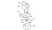
- FIG. 5 is an enlarged front view showing an embodiment of the pressing device 21.
- a mounting member 28 is provided at the lower end of the lifting rod 20, and the pressing member 22 of the pressing device 21 is detachably attached to the mounting member 28 by screws.
- the lower end of the pressing member 22 extends directly below the needle bar 9 and has a through hole 22a through which the sewing needle 11 is inserted. Therefore, when the needle bar 9 descends, the presser member 22 also descends and presses the material to be sewn from above. will take place.
- the structure up to this point is the same as that of a known presser foot device.
- This embodiment is further characterized in that a guide body 23 protruding downward is provided at the lower end of the pressing member 22 .
- the components 22, 23, etc. of the pressing device 21 may be made of a material such as metal.
- the guide body 23 has a substantially cylindrical shape and has a hollow portion (opening in the vertical direction) communicating with the through hole 22a of the presser member 22. It can pass vertically through the guide body 23 through the hollow portion.
- the guide body 23 does not form a complete cylinder, and is an open portion extending from the left front of the sewing needle 11 to the left side to the lower end of the guide body 23 when viewed from the front.
- (Notch) 29 is provided (see also FIG. 8).
- the opening (notch) 29 communicates with the hollow portion of the guide body 23, and a part of the upper thread (which is connected to the material to be sewn) passed through the eye 11a of the sewing needle 11 passing through the hollow portion.
- the opening 29 formed substantially on the left side in front view allows the upper thread to pass in the rotation direction of the hook 3. It can be said that it is formed to allow In this way, the structure allows the needle thread to pass out of the guide body 23 through the opening 29, so that the needle thread can be pulled out from the sewing needle according to the movement direction of the frame 5 over a wide range, as will be described later.
- 11 can be wound counterclockwise (ie in the direction of rotation of the hook 3).
- the front edge and rear edge of the opening 29 formed on the left generally correspond to the front edge 23 a and the rear edge 23 b of the material wall portion of the guide body 23 . That is, the opening 29 is bounded by a leading edge and a trailing edge so that, in response to the movement of the frame 5, when the upper thread attempts to bypass and move in another direction after exiting its opening. , the movement thereof is restricted by the front edge portion 23a or the rear edge portion 23b of the material wall portion of the guide body 23. As shown in FIG. In order to avoid the occurrence of hitch stitches caused by needle thread, the regulating operation by the front edge portion 23a plays an important role.
- the material wall portion of the guide body 23 closer to the front than the front edge of the open portion 29 (that is, the front edge portion 23a) will be referred to as the restricting portion 23a.
- the movement of the upper thread in the direction away from the front edge of the open portion 29 formed substantially on the left side, which the restricting portion, that is, the front edge portion 23a, intends to restrict, is a generally rightward movement. It is movement in the direction opposite to the direction of rotation (counterclockwise). Therefore, it can be said that the restricting portion 23 a of the guide body 23 is provided so as to restrict the movement of the needle thread in the direction opposite to the rotating direction of the hook 3 .
- the open portion 29 is provided so as to open up to the lower end of the guide body 23 . Therefore, the restricting portion 23a defining the front edge of the open portion 29 prevents the upper thread passing through the open portion 29 from moving in the direction opposite to the rotating direction of the hook 3 until it reaches the lower end of the guide body 23. designed to regulate. Therefore, in a state where the needle thread is regulated by the regulating portion 23a, the upper thread moves along the regulating portion 23a to the lower end of the guide body 23 as the sewing needle 11 descends, and passes downward through the open portion 29. As a result, the restriction by the restricting portion 23a is released.
- the restriction portion 23a of the guide body 23 is provided in an appropriate range from the front edge of the open portion 29 toward the front surface.
- the regulating portion 23a formed on the guide body 23 is arranged so that the upper thread is positioned on the right side of the sewing needle 11 when the sewing needle 11 pierces the material to be sewn in order to avoid the occurrence of hitch stitches caused by the upper thread. This is to prevent the sewing needle 11 from coming to the right (to make it wind around the sewing needle 11 counterclockwise).
- symbol V indicates the vertical movement trajectory (vertical movement line) of the sewing needle 11 .
- a restricting portion (front edge portion) 23a or 23a is provided on the guide body 23. At least the lower end thereof (the portion that abuts on the material to be sewn) is positioned to the left of the vertical locus V of the sewing needle 11 .
- the regulating portion 23a is provided to regulate the movement of the upper thread at a position deviated to the side (to the left) in the rotational direction of the hook 3 from the vertical movement line of the sewing needle 11. As shown in FIG.
- the front edge of the open portion 29, that is, the restricting portion (front edge portion) 23a formed on the guide body 23 is obliquely cut from above toward the lower left direction. It has a recessed shape (recessed portion). Due to such a sloped shape (recessed portion), the upper or middle opening of the open portion 29 is wider toward the front than the lower opening. , when slack occurs in the portion of the upper thread which is in a state of being restricted by the restricting portion 23a from the open portion 29, the looseness is absorbed at the wide opening portion, and the restricting portion 23a holds the upper thread.
- the front edge of the open portion 29, that is, the restricting portion (front edge portion) 23a formed on the guide body 23 may be formed vertically.
- the external shape of the guide body 23 is not limited to the substantially cylindrical shape as described above, and may be any shape.
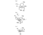
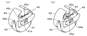
- 6A and 6B are diagrams showing a modification of the guide body 23, where (a) is a perspective view seen from the bottom side, (b) is a plan view, and (C) is a front view.
- the guide body 23-1 shown in FIG. 6 consists of two side wall surfaces connected at an appropriate angle (for example, about 90 degrees), and the space other than these side wall surfaces allows the sewing needle 11 to pass through. It functions as a space (corresponding to the hollow portion) and a space as an open portion 29 that allows passage of the upper thread in the rotating direction of the hook 3 .
- a side wall surface on the front side of the guide body 23-1 functions as a restricting portion 23a.
- FIG. 7 shows another modification of the guide body 23, where (a) is a perspective view from the bottom side, (b) is a plan view, and (C) is a front view.
- the guide body 23-2 shown in FIG. 7 is composed of three side wall surfaces that are sequentially connected at an appropriate angle (for example, about 90 degrees), and the space other than these side wall surfaces prevents the sewing needle 11 from passing through. It functions as a space for allowing passage (corresponding to the hollow portion) and a space as an open portion 29 for allowing passage of the upper thread in the rotating direction of the hook 3 .
- a side wall surface on the front side of the guide body 23-2 functions as a restricting portion 23a.
- the guide body 23 shown in FIGS. 5 to 7 has a wall surface portion, and the side edge portion on the front side of the wall surface portion functions as the restricting portion 23a.
- the restricting portion 23a may be formed in the form of a pin-like or linear thin columnar member without having a portion.
- two thin pillar members may be arranged to form a space as the open portion 29 between them, and one (front side) pillar member may function as the restricting portion 23a.
- an arc-shaped connecting foot portion may be provided for connecting the lower ends of the two thin column members.
- one or more separate thin column members may be provided in the middle of this arc-shaped connecting leg.
- the guide body 23 may consist of only one thin columnar member functioning as the restricting portion 23a.
- FIG. 8 is a diagram showing another modification of the pressing device 21, in which a cover 30 that covers the guide body 23 is provided below the pressing member 22.
- the structure of the hold-down device 21 is identical to that shown in FIG. 5, except for the elements associated with the cover 30.
- the cover 30 has a smoothly rounded convex curved surface (bowl shape) on the bottom side, and is provided with a relatively large diameter through hole so that the guide body 23 can be loosely accommodated. It has a recess that fits.
- a cover 30 is attached from the lower side of the guide body 23 and tightened with a screw 31 to assemble and fix the cover 30 to the pressing member 22, thereby covering the periphery of the side surface of the guide body 23.
- the guide body 23 is loosely accommodated inside the cover 30 with a gap, the function of the guide body 23 described above is not impaired.
- the periphery of the lower end of the guide body 23 is surrounded by the convex curved (bowl-shaped) bottom surface of the cover 30. Therefore, for example, the vertical stroke of the presser device 21 may be reduced in order to prevent the sewing material from fluttering. Also, it is possible to prevent the guide body 23 from being caught in the stitches on the moving sewing material.
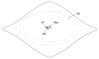
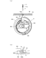
- FIG. 9 is a perspective view showing one embodiment of such a novel needle plate structure.
- FIG. 10 is an enlarged view showing the portion of the needle hole 19a in FIG. 9, where (a) is a plan view, (b) is a perspective view showing a cross section along line AA in (a), and (c). 4] is a perspective view of a main part illustrating a route of a bobbin thread D.
- the conventionally known needle hole 19a is generally a simple circular hole, as illustrated by dotted lines in FIG. 10(a).
- the vertical movement line (V in FIG. 5) of the sewing needle 11 passes through approximately the center of this circle.
- the needle plate 19 is provided with a guide hole 31 and a groove portion 32 in relation to the needle hole 19a.
- a guide hole 31 formed through the throat plate 19 is provided near the front side of the sewing machine, communicates with the needle hole 19a, and is closer to the rotation direction of the hook 3 than the vertical flow line of the sewing needle 11. (In FIG. 10(a), it is displaced to the left).
- the throat plate 19 has a groove 32 extending from the guide hole 31 in front of the needle hole 19a in the direction opposite to the rotational direction of the hook 3 (rightward in FIG. 10(a)).
- the groove portion 32 is open at the upper portion and at the portion communicating with the guide hole 31, but otherwise has a bottom surface 32a and side walls 32b (FIG.
- the bobbin thread D coming out of the hook 3 passes through the needle hole 19a and extends upward to form a seam on the material to be sewn.
- the bobbin thread D coming out of the hook 3 is constructed so as to be able to pass through not only the needle hole 19a but also the guide hole 31 communicating therewith.
- the guide hole 31 depending on the direction in which the frame 5 moves, as shown in FIG. It is constructed so that the portion can be guided to the near side of the needle hole 19a via the groove portion 32. As shown in FIG.
- the groove portion 32 Since the groove portion 32 has a bottom surface 32a, the portion of the bobbin thread D on the lower side remains in the guide hole 31, and the portion of the bobbin thread D on the upper side is bent and guided to the upper space of the groove portion 32. - ⁇
- the guide hole 31 is deviated from the vertical movement line of the sewing needle 11 toward the rotation direction (to the left) of the hook 3, and the groove 32 extends from the guide hole 31 to the hook before the needle hole 19a. 3, so that the bobbin thread D is guided to the guide hole 31 when the frame 5 is moved substantially leftward by detour movement control of the frame 5, which will be described later. Then, as the frame 5 moves substantially rightward to the needle drop position (target position), the bobbin thread D is guided substantially rightward from the guide hole 31 along the groove portion 32 .
- both sides of the groove portion 32 are the side walls 32b, the bobbin thread D is caught by the side walls 32b on the back side, and the bobbin thread D does not move to the back side of the vertical flow line of the sewing needle 11, and the needle thread 11 moves up and down. It is maintained on the front side of the flow line. In this way, the path of the bobbin thread D extending from the hook 3 to the needle hole 19a of the needle plate 19 is maintained on the front side of the vertical flow line of the sewing needle 11 without going to the back side, thereby performing a hitch stitch (especially a double hitch stitch). stitches) can be avoided.
- the groove portion 32 has the bottom surface 32a, the loop of the upper thread passing through the needle hole 19a while contracting the loop is not caught in the groove portion 32. There is no possibility of causing needle thread breakage. Furthermore, since the bobbin thread D is only held by the side wall 32b of the groove portion 32, when the bobbin thread D is pulled up as the needle thread is lifted, the bobbin thread D is easily released from the groove portion 32 and returns to the normal path. (that is, the path passing through the needle hole 19a), there is no adverse effect on the path formation of the bobbin thread D when forming the next stitch.
- the wall surface 31a on the back side of the guide hole 31 extends from the back toward the front in the rotation direction of the hook 3. (that is, toward the front left). That is, the wall surface 31a is inclined from the back to the front left so that the innermost part is closest to the vertical movement line of the sewing needle 11 and the frontmost part is farthest to the left from the vertical movement line of the sewing needle 11 .
- Such an inclination of the wall surface 31a at the connecting portion guides the bobbin thread D along the inclination when the frame 5 moves around and the path of the bobbin thread D is shifted from the needle hole 19a to the guide hole 31. It contributes to smooth transition to the hole 31 .
- the configuration of the connecting portion between the guide hole 31 and the needle hole 19a may be arbitrarily designed.
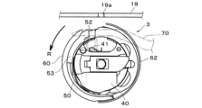
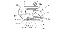
- FIG. 11 is a front view showing one embodiment of such a novel hook structure
- FIG. 12 is its plan view
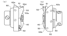
- FIG. 13(a) is its left side view
- FIG. 13(b) is its right side view.
- the hook 3 is arranged below the throat plate 19 .
- the hook 3 is a vertical full rotary hook (DB type).
- the hook 3 includes a bobbin case 40 that rotatably accommodates a bobbin (not shown) wound with a bobbin thread, an inner hook 50 that accommodates the bobbin case 40, and the sewing needle around the inner hook 50. 11, and an outer hook 60 that rotates in synchronization with the up-and-down movement of the hook 11.
- the inner hook 50 is fixed to the hook base 4 via a hook support 70 as is well known, and the bobbin case 40 is fixed inside the inner hook 50 .
- the outer hook 60 is fixed to a lower shaft (not shown) that rotates in synchronization with the vertical movement of the sewing needle 11, and rotates together with the lower shaft. In the vertical full rotary hook (DB type), the rotation direction R of the outer hook 60 is counterclockwise.
- a needle drop hole 51 for avoiding interference with the sewing needle 11 is provided in the upper front surface of the inner hook 50 .
- a concave portion 52 is formed in the front surface of the upper portion of the inner hook 50 at a position displaced from the needle hole 51 in the rotation direction R of the outer hook 60 .
- the concave portion 52 is open on the front side and the top and bottom, and the back side forms a wall surface 52a. It is configured to be placed in position.
- the wall surface 52a on the far side of the recess 52 at substantially the limit position in this way, the bobbin thread path (the position of the bobbin thread from the recess 52 toward the needle hole 19a) leading from the recess 52 to the sewing material can be adjusted to the needle drop ( It is possible to make it as far back (rear) as possible from the vertical movement locus), thereby expanding the area where hitch stitches caused by the bobbin thread can be avoided by the hook structure according to the present embodiment as much as possible. be able to.
- the left and right wall surfaces of the recess 52 are an upstream side wall 52b positioned upstream in the rotational direction R of the outer hook 60 and a downstream side wall 52c positioned downstream thereof.
- a thread pick-up member for directing (guiding) the bobbin thread let out from the bobbin thread bobbin toward the recess 52 of the inner hook 50 is provided at a predetermined location near the top of the bobbin case 40 (preferably below the recess 52). 41 is provided. As will be described later in detail, the bobbin thread let out from the bobbin in the bobbin case 40 passes through the opening of the recess 52 of the inner hook 50 via the thread take-up member 41 and is drawn upward. The bobbin thread that has passed through the recess 52 is entwined with a needle thread loop as is known in the art as the outer hook 60 rotates, and emerges from the needle hole 19a as the sewing needle 11 rises to form a stitch. Thus, the recess 52 provided in the inner hook 50 functions to form a path for the bobbin thread.
- the path of the bobbin thread from the hook 3 through the needle hole 19a of the throat plate 19 to the sewing material above passes through the recessed portion 52 provided in the upper front surface of the inner hook 50. It comes to the left side with respect to the vertical movement line (needle drop position) of the sewing needle 11 . That is, the bobbin thread let out from the bobbin thread is directed toward the concave portion 52 of the inner hook 50 by the thread take-up member 41 and passes through the concave portion 52 to the needle hole 19 a of the needle plate 19 .
- the concave portion 52 is formed at a position displaced from the needle drop hole 51 in the rotational direction R of the outer hook 60 (that is, at a position on the left side with respect to the vertical movement line of the sewing needle 11), and a wall surface 52a on the far side thereof. is formed at a substantially limit position where it does not interfere with the locus of movement of the blade point 61 of the outer hook 60, so that the route of the bobbin thread from the hook 3 to the needle hole 19a is on the far left side of the vertical flow line of the sewing needle 11.
- the path of the bobbin thread from the hook 3 to the needle hole 19a can be prevented from being on the right side of the vertical flow line of the sewing needle 11, thereby reducing the occurrence of hitch stitches.
- the bobbin thread path is surely on the left side of the needle drop (the vertical flow line of the sewing needle 11). Even if the inner side wall surface 52a of the concave portion 52 is shallower than the substantially limit position, occurrence of a hitch stitch is avoided.
- the frame 5 moves in a direction of approximately 40 degrees, for example, if the inner side wall surface 52a of the recessed portion 52 were shallower than the approximate limit position, the lower thread path would be the needle drop ( Since it is not on the left side of the vertical flow line of the sewing needle 11, but on the right side via the front side, hitch stitching cannot be avoided.
- downstream side wall 52c of the recess 52 may be provided with a structure for locking the bobbin thread during thread trimming.
- the downstream side wall 52c protrudes forward compared to the upstream side wall 52b, and has a protrusion 52d at its front end.
- a thread trimming device (not shown) is provided above the hook 3. When the thread trimming device cuts the thread, the portion of the bobbin thread extending from the hook 3 to the needle eye 19a is caught. and is guided leftward to the cutting position, where it is cut. When the bobbin thread moves leftward for such a thread cutting operation, the bobbin thread abuts the downstream side wall 52c and can move back and forth along the downstream side wall 52c as appropriate.
- a protrusion 52d is provided at the front end of the downstream side wall 52c so as to protrude somewhat from the wall surface.
- the outer hook 60 has a point 61 on its outer periphery for catching the loop of the upper thread pulled out from the eye 11 a of the sewing needle 11 .
- a thread separating spring (that is, an upper spring portion) 62 is fixed to the outer peripheral surface of the outer hook 60 by screws.
- a tip portion 62a of the thread separating spring 62 is formed in a pawl shape to guide the needle thread caught by the tip 61. As shown in FIG. Further, as shown in FIG.
- the front end edge (that is, the front side edge) 62b of the thread separating spring 62 is positioned deeper (rearward) than the inner side wall surface 52a of the recessed portion 52 of the inner hook 50. formed to be located.
- the front edge 62b of the thread separating spring 62 is formed so as not to protrude forward of the front side edge of the blade tip 61 of the outer hook 60 (the front side edge of the movement locus).
- a conventionally known thread separating spring has a portion (fin) in which the leading edge protrudes forward toward the rear in the rotation direction in order to push forward the needle thread loop that is caught as the outer hook rotates. consists of a shape. If the front edge of the thread separating spring protrudes in this way, the bobbin thread that is directed from the shuttle to the eye of the needle is also pushed forward, causing slack in the bobbin thread.
- such a protruding portion is formed at the front edge 62b of the thread separating spring 62 so that it does not come into contact with the bobbin thread guided by the recess 52. Therefore, the bobbin thread does not become slack.
- the thread separating spring 62 does not push the thread loop forward, so it is broadly referred to as an upper spring portion.
- the structure of the inner hook 50 is improved as described below.
- FIGS. 11 and 13(a), etc. in the outer periphery of the front surface of the inner hook 50, from the concave portion 52 in the downstream direction of rotation, over a range of about 1/4 arc angle (that is, 90 degrees), in detail
- a raised portion 53 projecting forward is formed over a range of less than 1/4 arc angle (that is, 90 degrees), particularly over a range of approximately 80 degrees in the illustrated example.
- the raised portion 53 has a chevron-shaped cross section, and is provided with a guide surface 53a that slopes forward toward the upstream side of the rotation, and is formed so that the height of the protrusion decreases toward the downstream side of the rotation. It is The raised portion 53 functions to push forward the needle thread loop caught by the blade tip 61 of the outer hook 60 . As the outer hook 60 rotates, the upper thread loop is pushed out while moving upward (from the rear to the front) of the protuberance 53, and passes around the inner hook 50 while moving on the front surface of the bobbin case 40. go. In this way, the raised portion 53 of the inner hook 50 can function as a substitute for the fins of the conventionally known thread separating spring.
- the protrusion 71 of the hook support 70 fixed to the hook base 4 can be fitted into the concave portion 52 of the inner hook 50, and is fitted.
- the inner hook 50 is fixed to the hook base 4 and prevented from rotating together with the outer hook 60 .
- An appropriate opening space is formed between the rear wall surface 52a of the recess 52 and the tip of the projection 71 of the hook support 70, and the bobbin thread guided to the recess 52 passes through this opening space to reach the needle. Go to hole 19a.
- the body 42 of the bobbin case 40 has an opening 42a in the upper front portion thereof for avoiding interference with the sewing needle 11 that has fallen through.
- the bobbin case main body 42 has a body portion (peripheral side surface) formed with a draw-out hole 42b for drawing out the bobbin thread from the bobbin stored therein, and a draw-out hole 42b for applying a constant tension to the bobbin thread.
- a thread tension spring 43 is attached.
- a guide groove 42c for regulating the passage position of the bobbin thread is formed above the pull-out hole 42b.
- the upper portion of the body of the bobbin case main body 42 is also opened, and this upper opening communicates with the opening 42a.
- the thread take-up member 41 is arranged in the upper front portion of the bobbin case 40, more specifically, in a leftward position below the opening 42a.
- the thread pick-up member 41 is constructed of a spring material so as to apply tension to the bobbin thread that is let out from the bobbin thread and moves toward the opening of the recessed portion 52 of the inner hook 50 . Therefore, hereinafter, the thread take-up member 41 is also referred to as a thread take-up spring.
- the thread take-up spring (thread take-up member) 41 has an annular or curved ring portion 41 a through which the bobbin thread let out from the bobbin thread is passed (hooked). It is directed to the opening of the recess 52 .
- the tension of the thread take-up spring 41 appropriately guides the bobbin thread toward the needle hole 19a so as to pass through the recess 52 (that is, regulates the path of the bobbin thread so that it passes through the recess 52), and absorbs slack in the bobbin thread. do.
- the thread take-up spring 41 extends substantially horizontally on the front surface of the bobbin case 40. One end (right end) opposite to the ring portion 41a is fixed to the bobbin case 40, and the ring portion 41a is a free end.
- the ring portion 41a is positioned almost directly below the recess 52 of the inner hook 50, and can swing up and down and left and right due to the movement of the bobbin thread passed through it due to the restoring force of the spring.
- the length from the fixed end (right end) of the thread take-up spring 41 to the ring portion 41a side end (left end) is relatively long as shown.
- the swinging range (stroke range) of the thread take-up spring 41 can be made relatively large, and relatively large slackness of the bobbin thread can be absorbed.
- the thread take-up member 41 by configuring the thread take-up member 41 with a spring material, it not only has the function of reliably guiding the bobbin thread toward the concave portion 52 of the inner hook 50, but also has the function of applying tension to the bobbin thread under various conditions. It can also have a function to prevent slack in the bobbin thread at the bottom.
- the bobbin thread pulled out from the pull-out hole 42b of the bobbin case 40 comes into contact with the thread tension spring 43, passes through the guide groove 42c, passes through the ring portion 41a of the thread take-up spring 41, is reversed upward, through the needle hole 19a.
- the bobbin thread pulled out from the pull-out hole 42b of the bobbin case 40 is passed through the thread tension spring 43 and then passed through the ring portion 41a of the thread take-up spring 41 without passing through the guide groove 42c.
- a guide member 44 may be provided in front of the thread take-up spring (thread take-up member) 41 in the bobbin case 40, as shown in FIG. 14(b).
- the guide member 44 is detachably attached to the front upper left portion of the bobbin case main body 42 with screws.
- the guide member 44 has a guide surface 44a protruding forward from its mounting portion, and the guide surface 44a is formed so as to be substantially continuous with the front surface of the bobbin case 40 (to form a substantially coincident surface). there is By providing the guide member 44 in this manner, the upper thread loop, which moves upward along the front surface of the bobbin case 40 as the hook 3 rotates, can be smoothly guided along the front surface of the bobbin case.
- the guide surface 44a of the guide member 44 is provided with an opening 44b penetrating in the front-rear direction.
- This opening 44b is for allowing the tip of a known picker (not shown) to be inserted.
- a well-known picker holds the needle thread on the side of the sewing needle when the needle thread is cut by a thread trimming device (not shown), so that a predetermined amount of thread remains and the needle thread comes out from the eye of the sewing needle. It is intended to prevent A known picker has a pair of left and right tips, and when the thread is cut, these tips are inserted into the opening 42a of the bobbin case 40, and the needle thread passing through the hook 3 is hooked on both tips and held.
- FIG. 15 is a block diagram showing an example of a sewing machine control system (that is, a sewing machine control device).
- ROM read-only memory and/or flash memory, hard disk, etc.
- readable and writable memory 103.
- control system includes a main shaft motor driver 104 that rotates the sewing machine main shaft 13, X-axis motor and Y-axis motor drivers 105 and 106 that move the frame 5 in the X and Y directions, respectively, A driver 107 for the jump motor for jumping the needle bar 9 and a driver 108 for the presser motor 24 for raising and lowering the presser device 21 are provided, and the corresponding motors are connected to the respective drivers. be done.
- the control system also has a user input/output interface 109 including the operation panel 6 .
- the operation panel 6 is composed of a touch panel that serves both for image display and for accepting user input operations, and various setting/control screens are displayed on the touch panel. A user can perform various operations and settings by performing a touch operation on an operation image or the like displayed on the screen of the touch panel.
- a communication interface (not shown) may be provided for communicating with external devices and/or internal or external communication networks.
- the next stitch is selected.
- detour control is performed to move the frame 5 in a detour.
- This bypass control can be performed by a program executed by the CPU 101 . That is, when the determining means determines that the direction in which the next stitch is formed belongs to the predetermined area, the CPU 101 and the program perform the jump control by the jump mechanism (107, etc.) and the feed mechanism (105).
- control means that is, detour control means
- detour control means for detouring the frame 5 .
- the roundabout movement of the frame 5 means that the needle thread extending downward from the sewing needle 11 in a state where the sewing needle 11 is jumped upward is directed to come out of the opening 29 of the guide body 23 of the presser device 21.
- the frame 5 is moved to the target position corresponding to the next stitch so that the upper thread coming out of the open portion 29 abuts the restricting portion 23a of the guide body 23.
- the movement of the frame 5 such that the upper thread coming out of the opening portion 29 abuts against the restricting portion 23a of the guide body 23 is a detouring movement so that the needle thread coming out of the opening portion 29 passes through the restricting portion 23a.
- the detouring movement means that the needle thread is pulled upward to the open portion 29 of the guide body 23 without immediately moving the frame 5 to the target position corresponding to the next stitch.
- the frame 5 is once moved in the direction of exiting from the opening portion 29, then the needle thread coming out of the opening portion 29 detours so as to contact (pass through) the restricting portion 23a, and finally corresponds to the next stitch. It is a movement to reach the target position.
- the regions in which the sewing direction in which the hitch stitch occurs due to the needle thread belongs belong to region ⁇ and region ⁇ .
- a part of the area ⁇ around 90 degrees (that is, an area in which the sewing direction is the back side of the sewing machine) is an area where hitch stitches can be avoided by detouring the frame 5 with a relatively small amount of detouring.
- this is called the first area S1.
- an example of the first area S1 is shown in FIG. In FIG. 16, as in FIG. 1, the reference point C located in the center of the drawing indicates the current needle drop position (the position of the needle hole 19a of the needle plate 19), and is scaled counterclockwise from 0 degrees to 360 degrees.
- An angle of less than a degree specifies the sewing direction from the reference point C to the next needle drop point (that is, the direction in which the next stitch is formed).
- the moving direction of the frame 5 corresponding to the area S1 in the sewing direction around 90 degrees is the area around 270 degrees, which is the opposite side (180 degrees opposite side).
- T1 an example of the movement target position of the frame 5 corresponding to the stitches in the sewing direction belonging to the first region S1 is indicated by T1 in FIG.
- the target position T1 can be reached by detouring the frame 5 with a relatively small detour amount.
- the range of the first region S1 is shown as a range of angles a to b in the drawing, and is a range of about 85 degrees to less than 112 degrees as an example, but as will be described later, this range can be variably set as appropriate. You can get it.
- the remaining region S2 of the region ⁇ and the region ⁇ to which the sewing direction in which the hitch stitch occurs due to the needle thread factor belongs is the region in which the hitch stitch is avoided by detouring the frame 5 with a relatively large detour amount. Roughly speaking, this is called the second area.
- the second region S2 includes the rest of the region ⁇ and all of the region ⁇ shown in FIG.
- the moving direction of the frame 5 corresponding to the second area S2 is the opposite area (180 degrees opposite side). An example is indicated by T2 in FIG.
- the target position T2 corresponding to is relatively far and may be closer to the back side. Therefore, in order to reach the target position T2, it is necessary to detour the frame 5 by a relatively large detour amount.
- the range of the second region S2 is shown as a range of angles b to c in the figure, and is a range of about 112 degrees to 210 degrees as an example, but as will be described later, this range can also be variably set as appropriate.
- regions with different detour amounts are not limited to the two regions (S1, S2) as described above, and may be three or more regions.
- S0 indicates an area where the detour movement of the frame 5 is not performed, and this area S0 includes areas ⁇ and ⁇ shown in FIG.
- control means may perform the jump control once, twice, or more during the roundabout movement.
- the control means when the direction in which the next stitch is formed belongs to the first region S1, the control means performs the jump control once during the detour movement, and the direction in which the next stitch is formed is controlled. belongs to the second region S2, the jump control is performed twice during the roundabout movement.
- FIG. 17 is a diagram exemplifying some loci of detour movement of the frame 5 executed by the frame detour control by the control means.
- C indicates the (current) needle drop position (base point) at the start of the detour movement
- T1 and T2 indicate the needle drop positions (target positions) at the end of the detour movement.
- FIG. 18 is a cross-sectional plan view showing the relationship between the needle thread T and the guide member 23 of the presser device 21 when the frame 5 is moved around. The portion of needle thread T entering 11a is shown in horizontal cross section.
- the sewing needle 11 is positioned higher than the guide body 23, so the cross section of the guide body 23 and the cross section of the sewing needle 11 (and the portion of the needle thread T entering the eye 11a thereof) are different. Note that cross-sections) do not indicate flush cross-sections.
- FIG. 17(a) shows the trajectory of the detour movement when the direction in which the next stitch is formed belongs to the first region S1.
- one (1 stitches) jump control.
- the needle bar 9 (sewing needle 11) raised at the reference point C is set to a jump state by the jump mechanism and held upward.
- the presser motor 24 stops, and the presser device 21 stops at a predetermined upper position.
- the movement of the frame 5 is controlled in the direction in which the upper thread T extending downward from the sewing needle 11 comes out of the opening 29 of the guide body 23 .
- the movement of the frame 5 at this time is indicated by A1 in FIG. 17(a).
- the end point m1 of the movement A1 of the frame 5 may be set with appropriate XY coordinate values. Considering the efficient (compact) detour movement, it is preferable to set the end point (that is, the middle point) m1 of A1 so that the movement A1 of the frame 5 is diagonally forward left as shown in the drawing. However, it is not limited to this, and may be appropriately set within the scope of the present embodiment.
- FIG. 18(a) shows a state in which the needle thread T is pulled out obliquely forward left from the open portion 29 of the guide body 23 in accordance with the movement A1 of the frame 5 at this time. When the frame 5 reaches the intermediate point m1, jump control for one stitch ends.
- FIG. 17(a) shows a state in which the needle thread T comes into contact with the regulating portion 23a with the movement A2 of the frame 5 at this time.
- the upper thread T protruding from the eye 11a of the sewing needle 11 is positioned on the left side of the sewing needle 11.
- the needle bar 9 (sewing needle 11) and the presser device 21 are lowered.
- the operation timing is appropriately adjusted so that the frame 5 reaches the target position T1 and completes the roundabout movement before the descending sewing needle 11 and the presser device 21 come into contact with the upper surface of the material to be sewn.
- FIG. 17(b) shows the trajectory of the detour movement when the direction in which the next stitch is formed belongs to the second region S2.
- two (2 stitches) jump control The needle bar 9 (sewing needle 11) raised at the reference point C is set to a jump state by the jump mechanism and held upward.
- the presser motor 24 stops, and the presser device 21 stops at a predetermined upper position (top dead center).
- the movement of the frame 5 is controlled in the direction in which the upper thread T extending downward from the sewing needle 11 comes out of the opening 29 of the guide body 23 .
- the movement of the frame 5 at this time is also indicated by A1 in FIG. 17(b) in the same manner as described above.
- the end point (that is, the first intermediate point) m1 of the movement A1 of the frame 5 may be set with appropriate XY coordinate values.
- the end point of A1 (that is, the first intermediate point ) m1 should be set.
- the state in which the needle thread T is pulled out obliquely to the left from the open portion 29 of the guide body 23 in association with the movement A1 of the frame 5 is as shown in FIG. 18(a).
- FIG. 17(b) shows the movement of the frame 5 at this time.
- the movement A2 of the frame 5 is obliquely forward to the right as shown in the figure, and in the process of this movement A2, the needle thread T coming out of the open portion 29 of the guide body 23 comes into contact with the restricting portion 23a of the guide body 23, The rightward movement of the upper thread T is restricted by the restricting portion 23a.
- FIG. 18(b) shows the state when the upper thread T abuts against the regulating portion 23a during the movement A2.
- the upper thread T protruding from the eye 11a of the sewing needle 11 is positioned on the left side of the sewing needle 11.
- the end point (that is, the second intermediate point m2) of the movement A2 of the frame 5 may be set with appropriate XY coordinate values. Considering that the target position T2 and the regulating portion 23a are reliably abutted (applied), the end point of A2 (that is, the second An intermediate point m2) may be set.
- the second jump control ends when the frame 5 reaches the second intermediate point m2.
- the movement A2 reaches the end point (the second intermediate point m2), the upper thread T is wound around the restricting portion 23a counterclockwise.
- the frame 5 is moved from the second intermediate point m2 toward the target position T2 corresponding to the next stitch.
- the movement of the frame 5 at this time is indicated by A3 in FIG. 17(b).
- the movement A3 of the frame 5 is diagonally rightward and backward as shown in the figure.
- the upper thread T is entwined with the regulating portion 23a in a counterclockwise direction and is directed obliquely to the right.
- the point that the upper thread T protruding from the eye 11a of the sewing needle 11 is positioned on the left side of the sewing needle 11 is the same as the state shown in FIG. 18(b).
- the needle bar 9 (sewing needle 11) and the presser device 21 are lowered.
- the operation timing is appropriately adjusted so that the frame 5 reaches the target position T2 and the detour movement is completed before the descending sewing needle 11 and the presser device 21 come into contact with the upper surface of the material to be sewn. be.
- detour movement of the frame 5 is performed intermittently.
- sewing data (frame movement data) for each stitch and a jump control code are combined and programmed. data) and a jump control code, and sewing data for the next stitch (frame movement data to the target position T1).
- detour movement by jump control twice consists of a combination of sewing data for the first stitch (frame movement data to the first intermediate point m1) and a jump control code, and sewing data for the next one stitch (second intermediate point m1).
- Frame movement data to point m1) and a jump control code, and stitch data for the last stitch frame movement data to target position T2).
- the number of times of jump control in the frame detour control is not limited to one or two as described above, and may be three or more times, or may be only one time.
- the roundabout movement of the frame 5 is not limited to the intermittent movement as described above, and may be performed continuously.
- FIG. 17(c) shows an example in which the roundabout movement of the frame 5 is continuously performed.
- the target position is T2
- the roundabouts follow trajectories A1, A2, and A3 similar to (b).
- An example of continuous movement is shown.
- a parameter is set such that the frame 5 is moved continuously when the jump control code is consecutive. You can also do it on purpose.
- an upper thread slack preventing portion 200 is provided in the lower portion of the needle bar case 8.
- the needle thread slack preventing section 200 is arranged above a well-known needle thread locking device 400, and both ends of its base plate 201 are fixed to brackets attached to left and right side surfaces of the needle bar case 8 with screws.
- a pressing piece 203 is held by a screw 202 having a spring fitted to the shaft portion.
- a needle thread T (not shown in FIG. 3) hanging from the thread take-up 10 is passed between the base plate 201 and the pressing piece 203 .
- the screwing amount of the screw 202 By adjusting the screwing amount of the screw 202 and changing the elasticity of the spring, a slight tension is applied to the upper thread T passing between the base plate 201 and the pressing piece 203 by contact resistance.
- the needle thread T After passing through the needle thread slack preventing portion 200 , the needle thread T passes through the needle thread locking device 400 and is passed through the eye 11 a of the corresponding sewing needle 11 .
- the tension applied to the upper thread T by the screw 202 and the presser piece 203 of the upper thread slack prevention unit 200 is caused by the slackness of the upper thread T that is caught (wrapped) on the guide body 23 during detour movement control of the frame 5. It is sufficient that it can be prevented from falling downward. With this needle thread slack preventing portion 200, even if slack occurs in the portion of the needle thread T above the needle thread slack preventing portion 200 when the needle bar 9 jumps and when the thread take-up 10 that moves up and down descends, the upper thread T is prevented from becoming slack.
- the contact resistance of the thread slack preventing portion 200 prevents the upper thread T below it from becoming slack, and the needle thread T that is caught (wrapped) on the guide body 23 during detour movement control of the frame 5. can be prevented from dropping downward due to slack.
- the structure of the upper thread slack preventing portion 200 is not limited to that shown in the drawings, and any structure that prevents the upper thread T from becoming slack may be employed.
- the well-known needle thread locking device 400 may be used instead of providing the special needle thread slack preventing portion 200 . Since the needle thread slack preventing section 200 always applies tension to the needle thread T, even a slight contact resistance may affect thread tightening.
- the upper thread slack preventing section 200 may be made movable like the upper thread lock device 400 so that the tension is applied only when the frame 5 is controlled to detour.
- FIG. 19 is a flow chart showing an example of a computer program for executing sewing control consisting of all perfect stitches according to this embodiment. This program is stored, for example, in the storage device 103 shown in FIG. .
- the program shown in FIG. 19 starts when the sewing operation of a pattern (embroidery pattern or other sewing pattern) consisting of multiple stitches selected by the user is started.
- the value of a stitch counter n indicating the order of stitch formation is set to an initial value of 1.
- stitch movement amount data Pn (XY movement data of frame 5) for forming a stitch of the order (nth stitch) designated by the current value of stitch counter n is acquired.
- the needle movement direction of the stitch movement amount data Pn (that is, the direction of forming the next stitch) is calculated using the current needle drop position as a base point C.
- step St5 the frame 5 is moved to the target position corresponding to the stitch movement amount data Pn, the needle bar 9 is lowered, and one stitch is sewn.
- the detour movement of the frame 5 is not performed in the sewing operation in step St5.
- the region S0 shown in FIG. 16 includes the regions ⁇ and ⁇ shown in FIG. If the calculated needle movement direction (the direction in which the next stitch is formed) belongs to the area ⁇ , a perfect stitch can be formed simply by performing a normal sewing operation. On the other hand, if the calculated needle movement direction (the direction in which the next stitch is formed) belongs to region ⁇ , it is possible to avoid the occurrence of hitch stitches due to bobbin thread factors and form perfect stitches by the unique hook structure described above. can. Details are as follows.
- FIG. 20A and 20B are diagrams illustrating a mechanism for avoiding the hitch stitch caused by the bobbin thread by the hook structure according to this embodiment.
- FIG. 20A is a front view of the hook structure
- FIG. It is a top view which expands and shows the relationship of a bobbin thread.
- the hook 3 shown in FIG. 20 is similar to the hook 3 described above with reference to FIGS. 11 to 14 and the like. If the direction in which the next stitch is formed belongs to the area ⁇ , the frame 5 moves rightward and backward toward the target position corresponding to the next stitch.
- the bobbin thread D directed from the hook 3 to the needle hole 19a is pulled in the rightward direction as the frame 5 moves, but as shown in FIGS. , and the rightward movement of the bobbin thread D is restricted by the upstream side wall 52b of the recess 52 .
- the bobbin thread D coming out of the hook 3 passes through the left rear side of the vertical movement line of the sewing needle 11 toward the needle hole 19a, and is connected to the upper workpiece W, so that the sewing moves vertically.
- the bobbin thread D is always positioned on the far left side of the sewing needle 11 and never on the right side.
- occurrence of a hitch stitch caused by the bobbin thread in the area ⁇ is structurally avoided, and the entanglement of the needle thread T and the bobbin thread D realized in the hook 3 forms a perfect stitch.
- the material to be sewn (work cloth) W When the sewing needle 11 passes through the material to be sewn (work cloth) W, the material to be sewn flutters up and down. may move to the right of the tip of the needle.
- the thread take-up member 41 by giving the thread take-up member 41 a spring action, even if the bobbin thread D becomes slack due to fluttering of the material W to be sewn, etc., it will be positioned almost immediately below the recessed portion 52 of the inner hook 50. Since the spring action of the thread take-up member (thread take-up spring) 41 quickly absorbs the slack in the bobbin thread D, the bobbin thread D can be maintained in a taut state, and the bobbin thread D moves to the right from the tip of the sewing needle 11.
- step St8 it is determined whether or not the needle movement direction (the direction in which the next stitch is formed) calculated in step St3 belongs to the first region S1 (part of region ⁇ ) shown in FIG. . If YES, go to step St9. In step St9, frame detour movement control for the first area S1 composed of a small detour movement trajectory as shown in FIG. 17A is executed. If the determination in step St8 is NO, the needle movement direction (the direction in which the next stitch is formed) calculated in step St3 belongs to the second area S2 shown in FIG. 16 (the area including the rest of area ⁇ and area ⁇ ). means that In this case, the process proceeds to step St10, and frame detour movement control for the second region S2 formed of a large detour movement trajectory as shown in FIG. 17B is executed.
- FIG. 21 is a perspective view illustrating the function of the guide body 23 of the presser device 21 in detour movement control of the frame 5.
- FIG. 21(a) shows a perspective view of the state at this time.
- the frame 5 moves as indicated by the trajectory A2 in FIG. It comes into contact with the restricting portion 23a of the guide body 23 and is restricted.
- the sewing needle 11 and the presser device 21 are lowered by canceling the jump state of the needle bar 9 .
- FIG. 21(b) shows the state immediately before the descending sewing needle 11 enters the through hole 22a of the pressing member 22 of the pressing device 21.
- FIG. 21(b) shows the state immediately before the descending sewing needle 11 enters the through hole 22a of the pressing member 22 of the pressing device 21.
- the needle thread T which is connected to the material W from behind the eye 11a of the sewing needle 11, is hooked on the restricting portion 23a of the guide body 23 (specifically, the cutout portion of the restricting portion 23a), and Movement to the right of the vertical flow line of 11 is regulated, and the sewing needle 11 is held to the left.
- FIG. 21(c) shows the state immediately before the sewing needle 11 descends further, enters the guide body 23 of the presser member 22, and pierces the material W to be sewn.
- the sewing needle 11 descending inside the guide body 23 passes through the right side of the part of the upper thread T which is connected to the sewing material W while coming out from the rear of the eye hole 11a and being restricted by the restricting portion 23a.
- the guide body 23 of the presser device 21 reaches the bottom dead center, the lowering of the presser device 21 is stopped, and only the sewing needle 11 is further lowered thereafter.
- FIG. 21(d) shows a state in which the tip of the sewing needle 11, which is further lowered, has passed through the guide body 23 and is stuck in the material W to be sewn.
- the portion of the upper thread T connected to the sewing material W from behind the eye 11 a of the sewing needle 11 is restricted from moving rightward by the restricting portion 23 a of the guide body 23 , so that the portion of the needle thread T is positioned on the left side of the sewing needle 11 . while being held by the needle 11, it descends along the restricting portion 23a as the sewing needle 11 descends.
- FIG. 21(e) shows a state in which the needle thread T, which is connected to the sewing material W from behind the eye hole 11a, reaches below the lower end of the guide body 23 by further lowering the sewing needle 11.
- FIG. 21(e) shows a state in which the needle thread T, which is connected to the sewing material W from behind the eye hole 11a, reaches below the lower end of the guide body 23 by further lowering the sewing needle 11.
- the portion of the upper thread T that is connected to the sewing material W from behind the eyelet 11a is released from the regulating portion 23a and is entangled with the sewing needle 11 in the counterclockwise direction.
- the needle 11's eye is A portion of the needle thread T that extends from the rear of the hole 11a and connects to the upper workpiece W extends upward along the left side of the sewing needle 11 and reaches the workpiece W through the needle hole 19a.
- the needle thread T is held on the left side of the sewing needle 11 from the rear of the eyelet 11a to the upper workpiece W (needle hole 19a).
- FIG. 17(b) By moving the frame 5 to the first intermediate point m1 in a state in which the needle bar 9 is jumped by one stitch and the sewing needle 11 is held upward, the frame 5 is moved as indicated by A1 in FIG. 17(b). As shown in FIG. 18(a), the needle thread T extending downward from the rear of the eyelet 11a of the upper sewing needle 11 passes through the open portion 29 of the guide body 23 of the presser device 21 diagonally forward to the left. It will be in a state where it appears in the direction. A perspective view of the state at this time is shown in FIG. 21(a).
- the frame 5 is moved from the first intermediate point m1 to the second intermediate point m2 by continuing the jump of the needle bar 9 (assuming that the needle bar 9 has jumped by one more stitch), so that the frame 5 is shown in FIG. As indicated by locus A2 in b), it moves generally to the right.
- Jump control ends when the frame 5 reaches the second intermediate point m2.
- the end point (second intermediate point m2) of this movement A2 is reached, the upper thread T is entangled with the restricting portion 23a of the guide body 23 to the left.
- the needle thread T coming down from the sewing needle 11 and connected to the sewing material W is deeply entwined with the restricting portion 23a of the guide body 23 in a counterclockwise direction.
- frame detour movement by double jump control can reliably hook the needle thread T to the regulating portion 23a, thereby preventing hooking errors.
- the frame 5 moves as indicated by the trajectory A3 in FIG. 17(b).
- the upper thread T is entwined with the restricting portion 23a in a counterclockwise direction, and is directed obliquely to the right.
- the needle thread T which is connected to the sewing material W from behind the eye 11a of the sewing needle 11, is deeply hooked to the restricting portion 23a of the guide body 23 in a counterclockwise direction, preventing the sewing needle 11 from moving to the right of the vertical flow line. It is restricted and held to the left of sewing needle 11 . Since the jump control has ended, the needle bar 9 (sewing needle 11) and the presser device 21 are lowered while the frame 5 is moving from the second intermediate point m2 toward the target position T2.
- the state of the upper thread T in the process in which the sewing needle 11 further descends passes through the material to be sewn W and the needle hole 19a and reaches the hook 3 is the same as described above with reference to FIGS. is. That is, the portion of the upper thread T protruding from the rear of the eyelet 11a of the sewing needle 11 enters the hook 3 while maintaining the position on the left side of the sewing needle 11 (counterclockwise with respect to the sewing needle 11). , it is possible to form a seam that avoids the occurrence of a hitch stitch caused by a needle thread. In particular, in the region ⁇ of the second region S2, by avoiding the occurrence of the hitch stitch caused by the needle thread as described above, perfect stitches are formed.
- hitch stitches caused by the upper thread and hitch stitches caused by the lower thread are mixed.
- the occurrence of hitch stitch should also be avoided. Specifically, even if the frame bypass control causes the sewing needle 11 to be wound to the left, the double hitch stitch will occur if the bobbin thread is positioned behind the vertical flow line of the sewing needle 11 .
- Such bobbin thread-induced hitch stitches in region ⁇ are avoided by the unique throat plate construction associated with needle hole 19a of throat plate 19, as previously described. Details are as follows.
- FIG. 23 is a perspective view illustrating a mechanism for avoiding the hitch stitch caused by the bobbin thread by the structure of the throat plate 19 having the guide hole 31 and the groove portion 32 as described above.
- the frame 5 and the material to be sewn W between the presser device 21 and the throat plate 19 are omitted for ease of illustration.
- the upper side of thread D is omitted.
- the distance between the guide body 23 of the presser device 21 and the throat plate 19 (needle hole 19a) is depicted as if it were constant. .
- FIG. 23(a) shows that, in the frame detour movement control (double jump control) for the second region S2 performed in step St10, the frame 5 has generally moved to the first intermediate point m1 (in the diagonally forward left direction). indicates the state of the moment.
- the needle thread T extending downward from the rear of the eye 11a of the upper sewing needle 11 comes out obliquely forward left from the opening 29 of the guide body 23 of the presser device 21, as described above. state.
- the bobbin thread D which extends upward from the hook 3 and is connected to the sewing material W, passes through the needle hole 19a corresponding to the needle drop position before the frame 5 is moved. It is guided from the needle hole 19a to the guide hole 31 along with the movement in the forward left direction.
- FIG. 23(b) shows the frame detour movement control (double jump control) for the second area S2 performed in step St10 when the frame 5 has moved approximately to the second intermediate point m2 (approximately rightward). state.
- the needle thread T extending downward from the rear of the eyelet 11a of the upper sewing needle 11 is hooked on the regulating portion 23a of the guide body 23 as described above, and is positioned to the right of the vertical movement line of the sewing needle 11. Movement is restricted, and it is entwined counterclockwise with respect to the restricting portion 23a.
- the bobbin thread D moves from the first intermediate point m1 to the second intermediate point m2 (generally to the right) of the frame 5, it bends from the guide hole 31 and enters the upper space of the groove portion 32, and enters the groove portion 32. It is guided to the approximately right direction along.
- FIG. 23(c) shows the frame detour movement control (double jump control) for the second region S2 performed in step St10 when the frame 5 has moved approximately to the target position T2 (approximately toward the right back). state.
- the upper thread T extending downward from the rear of the eyelet 11a of the upper sewing needle 11 is entwined with the regulating portion 23a of the guide body 23 in a left-handed manner as described above.
- the side wall 32b Fig. 10 (b)
- the sewing needle 11 is further lowered and then raised. tangles and seams are formed.
- the upper thread T coming out from the rear of the eye 11a enters the hook 3 while positioned on the left side of the sewing needle 11 (counterclockwise with respect to the sewing needle 11) and is pulled out from the lower thread bobbin.
- the path of the bobbin thread D leading to the throat plate 19 is maintained on the front side of the vertical flow line of the sewing needle 11 as described above. Therefore, sewing that avoids both the hitch stitch due to the needle thread and the hitch stitch due to the bobbin thread (that is, the double hitch stitch) is realized.
- the thread take-up member 41 provided in the hook 3 is pulled out even if the bobbin thread D is pulled out as the frame 5 moves around by giving a spring effect to the thread take-up member 41 .
- the spring action quickly absorbs the slackness of the bobbin thread D, so that the bobbin thread D can be kept in a taut state.
- the thread take-up member (thread take-up spring) 41 applies tension to the bobbin thread that is let out upward from the hook 3 and directed toward the needle hole 19a of the throat plate 19 or the guide hole 31. It also functions (also serves) as a tension applying means provided below the throat plate 19 .
- the loop of the needle thread T caught by the tip 61 of the outer hook 60 passes through the inner hook 50, and the thread take-up 10 (Fig. 4) is lifted up to reduce the loop of the needle thread T while pulling the bobbin thread D. It is conveyed and lifted up.
- the groove 32 is formed to have a bottom surface 32a, the loop of the upper thread T passing through the needle hole 19a together with the bobbin thread D while shrinking the loop is caught in the groove 32.
- the bobbin thread D is only held by the inner side wall 32b (FIG.
- step St7 it is determined whether or not the value n increased by 1 is larger than the "total number of stitches" of the pattern currently being sewn. If NO, the process returns to step St2, and the processes after step St2 are repeated as described above for the value n incremented by 1 (that is, the "next stitch").
- YES is determined in step St7, and the program of FIG. 19 is terminated.
- FIG. 24 shows an example of a screen display on which various data related to frame detour control (various conditions for detour control) can be set/changed using the operation panel 6 (FIG. 2).
- the operation panel 6 has a touch-operable display screen, and required images, data, etc. are displayed on the display screen according to various operation modes.
- the operation mode is the setting mode, for example, a parameter setting screen 110 as shown is displayed on the display screen of the operation panel 6 .
- frame bypass control setting items numbered 21 to 30 are displayed together with their respective current setting values.
- at least one setting item is displayed, and the displayed setting items are sequentially switched by a scroll operation or the like.
- the current setting value for the selected setting item is displayed on the display unit 111 .
- the setting value switching key 112 By operating the setting value switching key 112 , the current setting value for the selected setting item is increased or decreased and displayed on the display section 111 .
- pressing the enter key 113 enables the changed set value.
- the item number 21 related to "use all perfect stitches (Apfs)" corresponds to setting means for setting whether to enable execution of frame detour movement control. For example, by setting Yes/No, it is switched whether or not execution of frame bypass movement control is enabled.
- the illustration shows a state in which "Yes” is set. This set value may be "ON/OFF” instead of "Yes/No".
- step St11 is inserted between steps St3 and St4 described above, and in this step St11, it is determined whether or not "use all perfect stitches (Apfs)" is set to YES (that is, detour movement of frame 5 is executed). (whether or not it is valid to do so). If step St11 is YES, the process proceeds to step St4, and as described above, detour movement control of frame 5 is executed. If step St11 is NO, step St4 is jumped to step St5, and detour movement control for frame 5 is not executed.
- Apfs use all perfect stitches
- Items numbered 22 to 24 are means for setting parameters a, b, and c that define the direction of stitch movement (stitch forming direction) in which frame detour control is performed. This corresponds to setting means for variably setting the range of S2 (FIG. 16). Boundary angles a and b that define the range of the first region S1 are variably set in items numbered 22 and 23, and out of the boundary angles b and c that define the range of the second region S2, b is set in item numbered 23. According to the setting, c is variably set in the item of number 24.
- the predetermined values a, b are manually operated by the user.
- c are variably set.
- determination of the regions S0 and S1 in steps St4 and St8 of FIG. 19 is performed.
- Items numbered 25 and 26 are means for setting parameters X1 and Y1 that define the first movement direction in frame detour control (that is, setting means for variably setting the detour movement path of frame 5). corresponds to setting means for variably setting the XY displacement coordinate position (relative coordinate position with respect to the base point C) of the first intermediate point m1 (FIG. 17).
- Items numbered 27 and 28 are means for setting parameters X2 and Y2 that define the second movement direction in frame detour control (setting means for variably setting the detour movement path of the frame). It corresponds to setting means for variably setting the XY displacement coordinate position (relative coordinate position with respect to the first intermediate point m1) of the second intermediate point m2 (FIG. 17).
- These parameters X1, Y1, X2, and Y2 may be initially set to predetermined values, and variably set by manually increasing or decreasing the predetermined values by the user.
- the current values (2.5 mm, -3.8 mm, 1.1 mm) of the respective parameters X1, Y1, X2, and Y2 illustrated in FIG. represents.
- the detour movement route of the frame 5 can be appropriately changed. For example, if a relatively large detour movement path is set, the guide body 23 of the presser device 21 can be reliably entwined with the upper thread, while the detour movement of the frame 5 takes extra time. reduce the overall production efficiency of On the other hand, if a relatively small detour movement path is set, the detour movement of the frame 5 does not take much time, and the overall production efficiency of sewing is improved. Therefore, such a setting means is useful because an appropriate frame detour path can be set according to the trade-off between sewing quality and production efficiency.
- Items numbered 29 and 30 are means for setting the effective minimum stitch length and the effective maximum stitch length to which frame detour control is applied.
- the effective minimum stitch length is the minimum stitch length (stitch length) to which frame detour control is applied
- the effective maximum stitch length is the maximum stitch length (stitch length) to which frame detour control is applied. value.
- 0.0 mm is initially set as the effective minimum stitch length
- 36.0 mm is initially set as the effective maximum stitch length. can be set to When this setting is applied to frame detour control, for example, if the length of the stitch to be formed next (stitch length) is within the set effective minimum stitch length and effective maximum stitch length, detour of frame 5 is performed. It may be configured to perform control.
- the length of the next stitch to be formed is between the set effective minimum stitch length and effective maximum stitch length. If the step determines YES, the process goes to step St4, but if NO, the process jumps to step St5.
- the configuration for setting various types of data (conditions for detour control) related to frame detour control is limited to manual operation by the user using the operation panel 6 of the sewing machine as described above.
- the program data for frame detour control is arbitrarily set and stored together with the sewing pattern program or embroidery pattern program data.
- various data related to frame detour control that is, conditions for detour control
- various data related to frame detour control are also variable. Included in one embodiment of setting means for setting.
- the frame detour movement control and the needle bar jump control by the jump mechanism are performed.
- the present invention can also be implemented in a sewing machine of the type that does not have a thread.
- the movement of the needle bar should be controlled so that the needle does not drop during the detour movement of the frame 5 in order to make the detour movement of the frame 5 .
- the rotational speed of the main shaft 13 during the roundabout movement of the frame 5 it is possible to control the needle drop during the roundabout movement of the frame 5 .
- the present invention is not limited to this, and can be applied to a single-head type sewing machine or a one-needle type sewing machine. Also, the present invention can be applied to either an embroidery sewing machine or a normal sewing machine.
- the holder (frame) for holding the sewing material is not limited to a flat type, and may be a rotary type such as a cap frame.
- the hook is not limited to a full-rotation vertical hook (DB type), but may be a horizontal hook, a half-rotation hook, or any other type of hook.
- the area where the hitch stitch occurs may differ from the above-described embodiment depending on the type of hook to be employed, its rotation direction, etc.
- the arrangement of the grooves 32 is changed), or the hook structure is modified accordingly (the arrangement of the recesses 52 is changed).
- the operation panel 6 may have a structure fixedly attached to the sewing machine, or may have a structure detachably attached to the sewing machine.
- a portable operation panel for example, a mobile computer or a portable terminal
- a setting means for manually setting the detour control conditions
- the setting means that is, the setting device
- the setting means consisting of such a portable operation panel has a communication function for communicating with the control device of the sewing machine, and exchanges setting information/data between them.
- setting means that is, a setting device
Landscapes
- Engineering & Computer Science (AREA)
- Textile Engineering (AREA)
- Sewing Machines And Sewing (AREA)
Priority Applications (5)
| Application Number | Priority Date | Filing Date | Title |
|---|---|---|---|
| KR1020247005691A KR20240062134A (ko) | 2021-09-30 | 2022-03-16 | 미싱의 가마 구조 및 미싱 |
| JP2023551035A JPWO2023053507A1 (ko) | 2021-09-30 | 2022-03-16 | |
| US18/694,520 US20240392485A1 (en) | 2021-09-30 | 2022-03-16 | Rotary hook construction for sewing machine and sewing machine |
| CN202280066362.3A CN118076773A (zh) | 2021-09-30 | 2022-03-16 | 缝纫机的旋梭构造以及缝纫机 |
| EP22875390.1A EP4411046A1 (en) | 2021-09-30 | 2022-03-16 | Sewing machine shuttle structure and sewing machine |
Applications Claiming Priority (2)
| Application Number | Priority Date | Filing Date | Title |
|---|---|---|---|
| JP2021-161556 | 2021-09-30 | ||
| JP2021161556 | 2021-09-30 |
Publications (1)
| Publication Number | Publication Date |
|---|---|
| WO2023053507A1 true WO2023053507A1 (ja) | 2023-04-06 |
Family
ID=85782141
Family Applications (1)
| Application Number | Title | Priority Date | Filing Date |
|---|---|---|---|
| PCT/JP2022/011963 WO2023053507A1 (ja) | 2021-09-30 | 2022-03-16 | ミシンの釜構造及びミシン |
Country Status (7)
| Country | Link |
|---|---|
| US (1) | US20240392485A1 (ko) |
| EP (1) | EP4411046A1 (ko) |
| JP (1) | JPWO2023053507A1 (ko) |
| KR (1) | KR20240062134A (ko) |
| CN (1) | CN118076773A (ko) |
| TW (1) | TW202323621A (ko) |
| WO (1) | WO2023053507A1 (ko) |
Citations (8)
| Publication number | Priority date | Publication date | Assignee | Title |
|---|---|---|---|---|
| JPH0268096A (ja) * | 1988-09-01 | 1990-03-07 | Hirose Mfg Co Ltd | 本縫いミシンの全回転かま |
| JPH06343780A (ja) | 1993-06-07 | 1994-12-20 | Juki Corp | ミシンのヒッチステッチ防止装置 |
| JP2515400B2 (ja) | 1989-07-31 | 1996-07-10 | ジューキ株式会社 | 自動縫製ミシン |
| JP2540051B2 (ja) | 1986-09-20 | 1996-10-02 | コツホス・アドラー・アクチエンゲゼルシヤフト | 回転ケ―スを持つミシン頭部を有する自動ミシンの運転方法 |
| JP2006239389A (ja) * | 2005-02-02 | 2006-09-14 | Sabun Kogyosho:Kk | ミシンの垂直回転釜 |
| JP2008023261A (ja) | 2006-07-25 | 2008-02-07 | Brother Ind Ltd | ミシン |
| JP2008086391A (ja) * | 2006-09-29 | 2008-04-17 | Hirose Mfg Co Ltd | ミシンの全回転釜 |
| JP2012213603A (ja) | 2011-04-01 | 2012-11-08 | Juki Corp | ミシン |
Family Cites Families (2)
| Publication number | Priority date | Publication date | Assignee | Title |
|---|---|---|---|---|
| JP2515400Y2 (ja) | 1990-05-02 | 1996-10-30 | 株式会社千徳 | パンフレットラック |
| JP2540051Y2 (ja) | 1991-03-04 | 1997-07-02 | 盟和産業株式会社 | 床構造体 |
-
2022
- 2022-03-16 WO PCT/JP2022/011963 patent/WO2023053507A1/ja active Application Filing
- 2022-03-16 KR KR1020247005691A patent/KR20240062134A/ko unknown
- 2022-03-16 CN CN202280066362.3A patent/CN118076773A/zh active Pending
- 2022-03-16 US US18/694,520 patent/US20240392485A1/en active Pending
- 2022-03-16 JP JP2023551035A patent/JPWO2023053507A1/ja active Pending
- 2022-03-16 EP EP22875390.1A patent/EP4411046A1/en active Pending
- 2022-09-20 TW TW111135495A patent/TW202323621A/zh unknown
Patent Citations (8)
| Publication number | Priority date | Publication date | Assignee | Title |
|---|---|---|---|---|
| JP2540051B2 (ja) | 1986-09-20 | 1996-10-02 | コツホス・アドラー・アクチエンゲゼルシヤフト | 回転ケ―スを持つミシン頭部を有する自動ミシンの運転方法 |
| JPH0268096A (ja) * | 1988-09-01 | 1990-03-07 | Hirose Mfg Co Ltd | 本縫いミシンの全回転かま |
| JP2515400B2 (ja) | 1989-07-31 | 1996-07-10 | ジューキ株式会社 | 自動縫製ミシン |
| JPH06343780A (ja) | 1993-06-07 | 1994-12-20 | Juki Corp | ミシンのヒッチステッチ防止装置 |
| JP2006239389A (ja) * | 2005-02-02 | 2006-09-14 | Sabun Kogyosho:Kk | ミシンの垂直回転釜 |
| JP2008023261A (ja) | 2006-07-25 | 2008-02-07 | Brother Ind Ltd | ミシン |
| JP2008086391A (ja) * | 2006-09-29 | 2008-04-17 | Hirose Mfg Co Ltd | ミシンの全回転釜 |
| JP2012213603A (ja) | 2011-04-01 | 2012-11-08 | Juki Corp | ミシン |
Also Published As
| Publication number | Publication date |
|---|---|
| KR20240062134A (ko) | 2024-05-08 |
| CN118076773A (zh) | 2024-05-24 |
| EP4411046A1 (en) | 2024-08-07 |
| TW202323621A (zh) | 2023-06-16 |
| JPWO2023053507A1 (ko) | 2023-04-06 |
| US20240392485A1 (en) | 2024-11-28 |
Similar Documents
| Publication | Publication Date | Title |
|---|---|---|
| JP5427438B2 (ja) | ミシン | |
| WO2023053508A1 (ja) | ミシンの制御装置及び設定装置並びにミシン | |
| JP2002306876A (ja) | 穴かがりミシン | |
| WO2023053507A1 (ja) | ミシンの釜構造及びミシン | |
| WO2023053506A1 (ja) | ミシンの針板構造及びミシン | |
| WO2023053505A1 (ja) | ミシン及び押え装置 | |
| WO2020054556A1 (ja) | コード材を縫着可能なミシン及びコード材を供給する装置並びにコード案内体 | |
| WO2020054555A1 (ja) | コード材を縫着可能なミシン及びコードカット装置 | |
| JP2006068380A (ja) | 間歇ステッチ縫いミシン | |
| JP2009160263A (ja) | ボタン穴かがりミシン | |
| JP3570764B2 (ja) | ロックミシン | |
| US12173435B2 (en) | Controlling device and method for sewing machine, and sewing machine | |
| JP5021245B2 (ja) | ボビンケース | |
| WO2020054557A1 (ja) | コード材を縫着可能なミシン及びコード材の縫い出しを制御する方法 | |
| JP3821136B2 (ja) | 針糸繰り装置付ミシン | |
| JPH0631076A (ja) | ミシンにおける自動縫い調子制御装置 | |
| JP2008086391A (ja) | ミシンの全回転釜 | |
| JP2003260281A (ja) | ミシン | |
| JP2016504124A (ja) | 少なくとも1つの本縫い回転ルーパーを備える刺繍機 | |
| KR20210029945A (ko) | 히치 스티치용 회전북통에 구비된 윗실루프 가이드수단 | |
| JP2001137575A (ja) | スプレッダー天秤の糸案内装置 | |
| JPH11114272A (ja) | 多針ミシン | |
| JP2004141652A (ja) | ボタン付けミシン | |
| JPH08323083A (ja) | 縁かがり縫いミシン | |
| JP2003326054A (ja) | ボタン付け環縫いミシン |
Legal Events
| Date | Code | Title | Description |
|---|---|---|---|
| 121 | Ep: the epo has been informed by wipo that ep was designated in this application |
Ref document number: 22875390 Country of ref document: EP Kind code of ref document: A1 |
|
| DPE1 | Request for preliminary examination filed after expiration of 19th month from priority date (pct application filed from 20040101) | ||
| WWE | Wipo information: entry into national phase |
Ref document number: 2023551035 Country of ref document: JP |
|
| WWE | Wipo information: entry into national phase |
Ref document number: 18694520 Country of ref document: US |
|
| WWE | Wipo information: entry into national phase |
Ref document number: 202280066362.3 Country of ref document: CN |
|
| NENP | Non-entry into the national phase |
Ref country code: DE |
|
| ENP | Entry into the national phase |
Ref document number: 2022875390 Country of ref document: EP Effective date: 20240430 |