WO2023047580A1 - レドックスフロー電池システム - Google Patents
レドックスフロー電池システム Download PDFInfo
- Publication number
- WO2023047580A1 WO2023047580A1 PCT/JP2021/035379 JP2021035379W WO2023047580A1 WO 2023047580 A1 WO2023047580 A1 WO 2023047580A1 JP 2021035379 W JP2021035379 W JP 2021035379W WO 2023047580 A1 WO2023047580 A1 WO 2023047580A1
- Authority
- WO
- WIPO (PCT)
- Prior art keywords
- electrode
- channel
- electrolyte
- frame
- cell
- Prior art date
- Legal status (The legal status is an assumption and is not a legal conclusion. Google has not performed a legal analysis and makes no representation as to the accuracy of the status listed.)
- Ceased
Links
Images


Classifications
-
- H—ELECTRICITY
- H01—ELECTRIC ELEMENTS
- H01M—PROCESSES OR MEANS, e.g. BATTERIES, FOR THE DIRECT CONVERSION OF CHEMICAL ENERGY INTO ELECTRICAL ENERGY
- H01M8/00—Fuel cells; Manufacture thereof
- H01M8/18—Regenerative fuel cells, e.g. redox flow batteries or secondary fuel cells
- H01M8/184—Regeneration by electrochemical means
- H01M8/188—Regeneration by electrochemical means by recharging of redox couples containing fluids; Redox flow type batteries
-
- H—ELECTRICITY
- H01—ELECTRIC ELEMENTS
- H01M—PROCESSES OR MEANS, e.g. BATTERIES, FOR THE DIRECT CONVERSION OF CHEMICAL ENERGY INTO ELECTRICAL ENERGY
- H01M8/00—Fuel cells; Manufacture thereof
- H01M8/02—Details
- H01M8/0271—Sealing or supporting means around electrodes, matrices or membranes
- H01M8/0273—Sealing or supporting means around electrodes, matrices or membranes with sealing or supporting means in the form of a frame
-
- H—ELECTRICITY
- H01—ELECTRIC ELEMENTS
- H01M—PROCESSES OR MEANS, e.g. BATTERIES, FOR THE DIRECT CONVERSION OF CHEMICAL ENERGY INTO ELECTRICAL ENERGY
- H01M8/00—Fuel cells; Manufacture thereof
- H01M8/18—Regenerative fuel cells, e.g. redox flow batteries or secondary fuel cells
-
- Y—GENERAL TAGGING OF NEW TECHNOLOGICAL DEVELOPMENTS; GENERAL TAGGING OF CROSS-SECTIONAL TECHNOLOGIES SPANNING OVER SEVERAL SECTIONS OF THE IPC; TECHNICAL SUBJECTS COVERED BY FORMER USPC CROSS-REFERENCE ART COLLECTIONS [XRACs] AND DIGESTS
- Y02—TECHNOLOGIES OR APPLICATIONS FOR MITIGATION OR ADAPTATION AGAINST CLIMATE CHANGE
- Y02E—REDUCTION OF GREENHOUSE GAS [GHG] EMISSIONS, RELATED TO ENERGY GENERATION, TRANSMISSION OR DISTRIBUTION
- Y02E60/00—Enabling technologies; Technologies with a potential or indirect contribution to GHG emissions mitigation
- Y02E60/30—Hydrogen technology
- Y02E60/50—Fuel cells
Definitions
- the present invention relates to a redox flow battery system.
- a redox flow battery is known as a large-capacity storage battery.
- a redox flow battery generally has an ion-exchange membrane that separates the electrolyte and electrode materials provided on both sides of the ion-exchange membrane. It can be carried out.
- the current density is a factor that determines the performance of redox flow batteries, and the current density that can be passed is determined by the cell resistance.
- the cell resistance includes the electrical resistance of the bipolar plate and electrode materials, the contact resistance between the bipolar plate and the electrode material, the reaction resistance on the electrode surface, the proton transfer resistance in the electrolyte, the proton ion transfer resistance in the ion exchange membrane, etc. It is the synthesis of all elements. Among them, the reaction resistance on the electrode surface behaves particularly complicatedly.
- Patent Document 1 discloses a cell frame that can adjust the pressure difference between the pressure of the positive electrode electrolyte and the pressure of the negative electrode electrolyte acting on the members in the cell.
- the frame provided in the cell frame has a positive electrode electrolyte flow channel that is a flow channel for the positive electrode electrolyte and a negative electrode electrolyte flow channel that is a flow channel for the negative electrode electrolyte. It is described that the structure of the channel and the structure of the negative electrode electrolyte channel are different. Slit length, cross-sectional shape, cross-sectional area, etc. are mentioned as the structure to be varied.
- Patent Document 1 the pressure difference between the pressure of the positive electrode electrolyte and the pressure of the negative electrode electrolyte is adjusted. Since the cross-sectional shape and cross-sectional area are different, the frames for the positive electrode and the negative electrode have different structures, and the two surfaces sandwiching the ion exchange membrane are not symmetrical. In the present invention, the structure of the frame for sending the vanadium liquid to the positive electrode and the negative electrode is completely the same, but the characteristics are improved by providing a certain branch at the inlet and making a difference between the inlet and the outlet.
- a carbon electrode and an electrolytic solution containing vanadium ions (V) are used.
- V vanadium ions
- the electrolytic solution electrons are transferred to the electrode when the valence of V ions changes, but it is necessary to quickly remove the V ions whose valences have changed.
- the liquid must flow uniformly in one direction at a constant speed.
- the transfer of electrons on the surface of the electrode is a kind of chemical reaction, the higher the temperature, the faster the reaction. Therefore, the higher the temperature of the electrolytic solution, the better.
- Non-Patent Document 2 experiments were conducted while varying the temperature from 15°C to 55°C, and it is shown that the higher the temperature, the lower the cell resistance and the higher the cell performance. Therefore, the ability to operate at 40°C or higher is extremely advantageous in terms of cell performance, but the above two problems, that is, the deterioration of the carbon electrode and the deposition of vanadium solution, are said to occur. Operation was never put into practice.
- the present invention has been proposed in view of such conventional circumstances, and reduces the deterioration of the electrodes, makes the flow of the electrolytic solution uniform, and enables high-performance operation at relatively high liquid temperatures.
- An object of the present invention is to provide a redox flow battery system.
- One aspect of the present invention includes at least an ion-exchange membrane, electrodes provided on both sides of the ion-exchange membrane, a frame provided with a flow path so that an electrolytic solution circulates inside the electrodes,
- the circulation means for the electrolyte solution and the bipolar plate provided inside the frame so as to be in contact with the electrode are used as a unit cell, and one or more cells are stacked, and the frame includes the circulation a cell inlet channel to which the electrolytic solution is supplied from means; an electrode-previous channel through which the electrolytic solution supplied from the cell inlet channel flows along the width direction of the frame; one or more electrode inlet channels for supplying the electrolyte to the electrodes inside the frame; and discharging the electrolyte that has passed through the electrodes from the inside of the frame to channels provided in the frame.
- the redox flow battery system is characterized in that a cell outlet channel is formed to return the electrolyte sent from the channel to the circulation means.
- the flow path formed in the frame may satisfy the following conditions.
- the electrolytic solution is a sulfuric acid solution containing vanadium
- the electrodes are made of heat-treated carbon felt
- the liquid temperature of the electrolytic solution is 40° C. to 80° C. (“ ⁇ ” is , represents the lower limit or more and the upper limit or less, the same applies hereinafter).
- the electrode is made of felt made of carbon fiber, after hydrophilization heat treatment in air at 400 to 500° C., at a temperature of 800° C. or higher in vacuum or in an inert atmosphere. It can be heat treated.
- the degree of vacuum attainment in the vacuum may be 0.05 to 0.5 Pa.
- the ion exchange membrane may be a polytetrafluoroethylene (PTFE)-based cation exchange membrane.
- PTFE polytetrafluoroethylene
- Another aspect of the present invention includes at least an ion-exchange membrane, electrodes provided on both sides of the ion-exchange membrane, and a frame provided with a flow path so that an electrolytic solution circulates inside the electrodes.
- the body, the electrolyte circulation means, and the bipolar plate provided inside the frame so as to be in contact with the electrode constitute a unit cell, and one or more of the cells are stacked, and the electrolyte is vanadium.
- the electrodes are made of heat-treated carbon felt, and the liquid temperature of the electrolyte is controlled to be within the range of 40° C. to 80° C. is.
- the present invention it is possible to provide a redox flow battery system that reduces deterioration of the electrodes, makes the electrolyte flow uniform, and enables high-performance operation at relatively high liquid temperatures.
- FIG. 1 is a schematic diagram illustrating the mechanism of a redox flow battery.
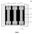
- FIG. 2 is a cross-sectional view showing the configuration (three-cell stack) of the redox flow battery system according to one embodiment of the present invention.
- FIG. 3 is a schematic diagram showing the configuration (multiple cells) of a redox flow battery system according to one embodiment of the present invention.
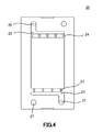
- FIG. 4 is a schematic diagram showing a frame in one aspect of the present invention.
- FIG. 5 is an example of the results of a charge/discharge test in Example 1.
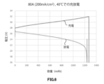
- FIG. FIG. 6 is a diagram showing the results of charging and discharging in the third cycle at 40° C. in Example 2.
- FIG. 5 is an example of the results of a charge/discharge test in Example 1.
- FIG. 6 is a diagram showing the results of charging and discharging in the third cycle at 40° C. in Example 2.
- FIG. 1 is a schematic diagram illustrating the mechanism of a redox flow battery.
- a redox flow battery is a type of secondary battery, and is a battery that charges and discharges by performing an oxidation-reduction reaction through an ion-exchange membrane while circulating an electrolytic solution in the cell.
- a sulfuric acid solution containing vanadium is used as the electrolyte, and as shown in FIG. 1, electrons are emitted from the positive electrode during charging.
- V 5+ and trivalent vanadium (V 3+ ) is reduced to divalent vanadium (V 2+ ) on the negative electrode side.
- an oxidation-reduction reaction proceeds in a manner opposite to that during charging.
- FIG. 2 is a cross-sectional view showing the configuration (three-cell stacking) of the redox flow battery system according to one embodiment of the present invention.
- One aspect of the present invention includes at least an ion-exchange membrane 10, electrodes 40 provided on both sides of the ion-exchange membrane 10, and a frame provided with a channel 35 so that an electrolytic solution circulates inside the electrodes 40. body 20, an electrolyte circulation means 30 (for example, having an electrolyte tank 31 and a pump 32), and a bipolar plate 50 (black part) as one unit cell, and the redox flow battery system 100 is formed by stacking one or more cells.
- an electrolyte circulation means 30 for example, having an electrolyte tank 31 and a pump 32
- a bipolar plate 50 black part
- the frame 20 has a cell inlet channel 21 to which the electrolytic solution is supplied from the circulation means 30, and an electrode pre-flow channel in which the electrolytic solution supplied from the cell inlet channel 21 flows along the width direction of the frame 20.
- one or more electrode inlet channels 23 for supplying electrolyte from the electrode pre-electrode channel 22 to the electrode 40 inside the frame 21;
- One or more electrode exit paths 24 serving as paths for discharging to the flow path provided in the body 20, and the electrolyte solution sent from the one or more electrode exit paths 24 flows along the width direction of the frame 20 and is collected.
- a cell outlet channel 26 for returning the electrolytic solution sent from the electrode post-flow channel 25 to the circulation means 30 (see FIG. 4).
- the electrolytic solution is a sulfuric acid solution containing vanadium
- the electrodes are made of heat-treated carbon felt
- the liquid temperature of the electrolytic solution is controlled to be within the range of 40°C to 80°C. That is, as will be described later, conventionally, it was often cooled to 40 ° C. or less, but in the present invention, such cooling operation is almost unnecessary, and the relatively high temperature of 40 ° C. to 80 ° C. is used. It can be suitably used even at the charging/discharging temperature.
- Each configuration of the redox flow battery system will be described below.
- Ion exchange membrane> In a redox flow battery, charging and discharging are performed by changing the valence of vanadium ions in the vanadium solution. I have to go back and forth. What guarantees this is an ion exchange membrane that allows protons to pass but not electrons. That is, since the ion exchange membrane is a basic component for establishing a redox flow battery, the properties of the ion exchange membrane determine the basic performance of the battery.
- Ion exchange membranes for redox flow batteries include cation exchange membranes and anion exchange membranes.
- the ion exchange membrane is H + in the case of a cation exchange membrane, and OH ⁇ in the case of an anion exchange membrane.
- a cation exchange membrane even a small amount of vanadium ions are allowed to pass through, but in the case of an anion exchange membrane, vanadium ions do not pass through, so in order to maintain a high coulombic efficiency, an anion exchange membrane is better.
- an anion exchange membrane is better.
- Advantageous however, once the replacement membrane is installed, it is very difficult to replace it, so it must have the same service life as the cell stack, and generally the service life required for the cell stack is 10 years or longer.
- PTFE polytetrafluoroethylene
- a sulfone group is added to the PTFE skeleton to create a path for protons. Basically, the required characteristics are almost the same as the ion exchange membrane used for fuel cells, and similar membranes can be used.
- the thinness limit of the ion exchange membrane is about 30 ⁇ m, and it is thought that the thinness limit is about 50 ⁇ m for a stack with a scale of 1 kW or more.
- Electrodes must be conductive, but they must be used in an aqueous solution of strong acid in a redox atmosphere. ) electrodes are preferably used. It is advantageous to have a high specific surface area in order to minimize the flow resistance of the electrolyte and increase the reactivity, and it is preferable to use carbon felt or carbon paper using carbon fibers with a diameter of 6 to 12 ⁇ m. Moreover, the carbon fiber is preferably a pitch-based carbon fiber. Carbon felt is often used in combination with a flat bipolar plate, and carbon paper is often used in combination with a bipolar plate having comb-shaped channels. The reason for this will be explained in detail in the section on bipolar plates.
- the content of the deterioration is attributed to the decrease of surface sp2 binding and the increase of sp3 binding. Since carbon fibers are electrically conductive due to the presence of sp2 bonds in graphite, electrical resistance increases when sp2 bonds are reduced. Even if the fiber as a whole does not change significantly, the conductivity of the surface decreases, so the resistance at the contact point between the fibers increases, resulting in a large increase in the resistance of the entire carbon felt. This deterioration progresses faster as the temperature of the vanadium solution is higher. In order to prevent this, it is necessary to proceed with graphitization, but if this is the case, the surface becomes water-repellent.
- Carbon is electrically conductive because of the presence of sp2 bonds.
- the graphitization progresses too much, it becomes water-repellent, and the vanadium ions in the aqueous solution cannot approach it, so the reactivity decreases.
- the cell resistance also rises because the flow of the liquid is obstructed by the increase.
- a carbon felt is made using carbon fibers with high conductivity by heat-treating at a temperature of 1200° C. or higher and performing a certain partial graphitization treatment.
- a carbon felt whose surface is made hydrophilic by heat treatment in the air at a temperature of 500° C.
- hydrophilic groups such as OH and COOH groups
- the once hydrophilized felt is heat-treated again at a temperature of 800° C. or higher in a vacuum or in a protective atmosphere such as Ar to proceed with graphitization while maintaining a certain level of hydrophilicity, resulting in a carbon electrode that does not deteriorate. Do you get it. Even when using an Ar atmosphere, air remains in the felt and is difficult to remove, so it is necessary to create a vacuum once. It is important to control the degree of vacuum at this time. If the degree of vacuum is too high, the surface becomes completely water-repellent and the flow resistance of the vanadium electrolytic solution increases. If the degree of vacuum is too low, the remaining O 2 or H 2 O reacts with C and the carbon fibers are consumed. Therefore, it is necessary to control the ultimate vacuum to 0.01 to 1 Pa. More preferably from 0.05 to 0.5 Pa.
- Bipolar plate In the case of a single cell, the bipolar plate is integrated with the collector plate for use. In the case of two or more cells, one side is a positive electrode and the other side is a negative electrode, so it is called a bipolar plate. In the redox flow battery system according to the present invention, cells can be connected by bipolar plates as shown in FIGS. The bipolar plates are not visible from the outside.) The positive electrode vanadium solution (V 4+ , V 5+ ) from the positive electrode tank and the negative electrode vanadium solution (V 2+ , V 3+ ) from the negative electrode tank enter each cell in parallel. flow in a straight line.
- both the ion-exchange membrane and the bipolar plate conduct electricity, but it is important that the ion-exchange membrane allows ions to flow but not electrons, while the bipolar plate allows electrons to flow but not ions. If the bipolar plate becomes ionic conductive due to the liquid soaking into it, the battery will not work.
- a carbon material is most suitable for the material of the bipolar plate because it has redox action in strong acidity, the potential for generating H 2 at the negative electrode is as high as possible, and the potential for generating O 2 at the positive electrode is as high as possible.
- porous materials are not preferable because they have ionic conductivity when the vanadium solution passes through them.
- As a carbon material it is most common to cut out a mass of artificial graphite to form a shape. Artificial graphite has a density of 1.7 to 1.9 g/cm 3 and graphite has a density of 2.2 g/cm 3 . Therefore, there is a void of about 14 to 23%, which allows the vanadium solution to pass through.
- the bipolar plate is made of artificial graphite impregnated with phenolic resin. Artificial graphite is sintered at 3000° C. to make a block, and then cut out from it, which is costly. In addition, graphite powder solidified with resin can also be used. However, in order to obtain conductivity equivalent to that of artificial graphite, it is necessary to increase the content of graphite powder to 80% or more, which is not easy to manufacture. When it comes to creating channels in the bipolar plate, the graphite must be processed, which further increases the cost. In order to reduce costs, there has been a great deal of research into creating flow channels by pressing a bipolar plate, which is made by hardening a graphite plate with resin.
- the method of creating channels in the bipolar plate is consistent with the idea of quickly extracting the vanadium ions after the reaction, as the reaction area can be set in a small area. Although it is very attractive, it is necessary for the material of the bipolar plate to have conductivity comparable to that of artificial graphite, and also to have the plasticity to form channels by press molding. Such materials have been reported, but are not commercially available.
- graphite sheets with increased density can be made by foaming graphite to make graphene and roll-forming it.
- This graphite sheet has a conductivity comparable to that of artificial graphite, but only a thin sheet can be produced due to roll forming.
- This graphite sheet can also be used if the bipolar plate can be flat.
- a graphite sheet obtained by adding a binder of 5 to 10% to this graphite sheet to increase its strength is also used.
- a thin carbon plate is used, the frame that holds it also becomes thin, making it difficult to form a flow path in the frame, making it difficult to uniformly supply the vanadium solution to the carbon electrode. Therefore, in the present invention, a carbon plate cut out from artificial graphite and impregnated with phenol to fill the holes is used.
- Frame> The basic role of the frame is to arrange and fix the bipolar plates, carbon electrodes, and ion-exchange membranes to maintain the structure. In addition, there are those in which the flow paths for sending the vanadium solution sent from the tank to each cell are arranged outside the frame and those in which the flow paths are formed in the frame. If the cell area is larger than 1 m2 , the amount of liquid to be flowed will be enormous, so it is better to use a thick pipe outside. is more complicated, and the thickness of the cell is also increased. Since the main object of the present invention is not a cell with a large cell area exceeding 1 m 2 but a small cell of about 500 cm 2 , a flow channel is formed in the frame.
- FIG. 4 shows a schematic diagram showing a frame in one embodiment of the present invention.
- the flow velocity and flow direction of the vanadium solution must be the same within the carbon electrode. A difference in velocity vectors creates a vortex and causes convection in the vanadium solution.
- the vanadium solution must first spread to the bottom outside the carbon electrode and be introduced all over at the same rate.
- the vanadium solution introduced into the carbon electrode in order for the vanadium solution introduced into the carbon electrode to have the same velocity everywhere, if the introduction port is widened over the entire surface, more vanadium solution will flow near the entrance. Therefore, it is necessary to reduce the number and area of the inlets.
- the inventors have found that the vanadium solution can be uniformly introduced into the carbon electrode when the conditions described later are satisfied, leading to the present invention.
- the frame 20 has a cell inlet channel 21 to which the electrolytic solution is supplied from the circulation means 30, and an electrolytic solution supplied from the cell inlet channel 21 along the width direction of the frame 20.
- one or more electrode inlet channels 23 that supply the electrolyte from the electrode pre-channel 22 to the electrode 40 inside the frame 21;
- One or more electrode exit paths 24 serving as a path for discharging from the inside of the frame 20 to a flow path provided in the frame 20, and the electrolyte sent from the one or more electrode exit paths 24 in the width direction of the frame 20
- a post-electrode flow channel 25 for flowing along and concentrating the electrolyte, and a cell outlet flow channel 26 for returning the electrolytic solution sent from the post-electrode flow channel 25 to the circulation means 30 are formed.
- the frame body 20 is provided with a channel 27 for the negative electrode liquid when the frame body 20 allows the positive electrode liquid to flow, and a channel 27 for the positive electrode liquid when the frame body 20 allows the negative electrode liquid to flow.
- Each channel must be sealed with an O-ring or a gasket so that the positive and negative electrodes do not mix.
- EPDM or FKM rubber is used for O-rings and gaskets because they must withstand strongly acidic aqueous solutions. By doing so, the frame 20 having the same structure can be used for the frame on the positive electrode side and the frame on the negative electrode side.
- the flow path formed in the frame 20 satisfy the following conditions.
- FIG. 4 An example is shown in FIG. 4 and explained.
- the inlet to the carbon electrode is 1 ⁇ 1.5 mm 2 and there are four of them, so the total cross-sectional area is 6 mm 2 .
- the flow path leading there is 5 ⁇ 1.5 mm 2 and 7.5 mm 2 .
- Materials such as polyethylene, polyolefins such as polypropylene, and vinyl chloride are used as materials for the frame because they have strong acid and oxidation-reduction effects.
- engineering plastics such as PPE and PSS are most suitable.
- PPE is difficult to mold, so modified PPE mixed with PS and PP can be used.
- a lubricant called talc is added to resin materials in order to adjust the coefficient of thermal expansion and elastic modulus. Since the lubricant basically contains a large amount of Si, it is desirable to add a minimum amount of lubricant. Lubricant-free materials are desirable if possible. If the resin material of the frame does not deteriorate, the risk of talc leaching is not so high, and whether talc dissolves in sulfuric acid depends on its composition. Therefore, these materials are not necessarily excluded.
- the present invention is directed to a redox flow battery that uses vanadium valence change to store electricity.
- the greatest advantage of vanadium is that both the positive and negative electrodes are the same vanadium. Since the ion-exchange membrane allows vanadium ions to pass through, albeit only slightly, the balance between the positive electrode and the negative electrode gradually shifts, causing a decrease in capacity, but the vanadium solution itself does not deteriorate. That is, if the positive electrode and the negative electrode are mixed to adjust the valence to +3.5, the original state can be restored.
- the greatest advantage of using vanadium is that the active material that stores batteries does not deteriorate and can be used forever.
- the amount of Si can be reduced by passing the vanadium solution through a 0.5 ⁇ m filter. Due to the circumstances described above, vanadium liquids of considerably high purity are generally used, which is a factor in pushing up costs. Si has been confirmed to have an adverse effect on the properties, and Si exists as silicate ions of SiO 4 4- , and it is thought that the silicate ions gradually polymerize to form particles of a certain size. be Therefore, it can be removed with a microfilter. It is unclear to what extent other heavy metal ions, alkaline earth ions, alkali ions, and ammonium ions are limited. According to the patent document (US7258947B2), the NH 4+ ion should be 20 ppm or less.
- Non-Patent Document 1 This seems to affect the ionic conductivity of the ion exchange membrane rather than affecting the battery reaction.
- the concentration of Si also greatly affects the precipitation behavior of V5 + . Since Si exists as fine particles, it is thought that this serves as a nucleus for the deposition of V 2 O 5 . Since the present invention assumes high-temperature operation at 40° C. or higher, it is important to use a vanadium solution with a low Si concentration, and one with a Si concentration of 10 ppm or less is used. Appropriate ranges for the vanadium concentration and the H 2 SO 4 concentration are summarized in Non-Patent Document 1 above.
- a vanadium concentration of 1.2-1.7M and a total H 2 SO 4 of 4-4.5M it is desirable to use a vanadium concentration of 1.2-1.7M and a total H 2 SO 4 of 4-4.5M. If the concentration is increased beyond this range, the danger of precipitation increases, and the concentration of the vanadium solution rises, resulting in an increase in flow resistance, resulting in marked deterioration of the properties. Moreover, if the concentration is made thinner than this, the amount of vanadium solution required to obtain a certain capacity increases, requiring a large tank. Regarding the concentration of sulfuric acid, the higher the H + concentration is , the better, in order to increase the ionic conductivity. Concentrations higher than 4.5 M are difficult to use because the flow resistance of the solution increases. Since high-temperature operation is considered in the present invention, the V concentration is set low to avoid precipitation, but the H 2 SO 4 concentration must be maintained within the range of 4-4.5M.
- Example 1 Three cells with an electrode effective area of 5 ⁇ 10 cm 2 were assembled as shown in FIG.
- Two IWAKI NRD-08ZTV24-N pumps were used, and 500 mL of 1.7M vanadium solution manufactured by LE System was used for both electrodes.
- the pump was operated at 24 V DC and the flow rate was 250-300 mL/min.
- the number of revolutions of the pump was constant, but the flow rate slightly changed with charging and discharging, and the flow rate slightly changed between the positive electrode and the negative electrode. This is thought to be due to the fact that the density and viscosity change slightly as the valence changes.
- Carbon felt was SGL SIGRCELL GFD4.6 activated and cut into 5 ⁇ 10 cm 2 .
- Chemours Nafion NR212 was used as an ion exchange membrane.
- the frame was machined out of a rigid PVC plate.
- the vanadium solution flow path was sealed with an EPDM O-ring.
- cross-sectional area of the channel satisfies the following conditions.
- Cross-sectional area of cell inlet channel > Cross-sectional area of channel immediately before carbon electrode > Cross-sectional area of carbon electrode inlet channel x Number of inlet channels
- Cross-sectional area of cell outlet channel ⁇ Cross-sectional area of cell inlet channel Current immediately before carbon electrode
- Cross-sectional area of channel ⁇ Cross-sectional area of channel immediately after carbon electrode
- Cross-sectional area of outlet channel of carbon electrode x Number of outlet channels
- the dimensions of the flow path were set in the same configuration as in Example 1, except that That is, in Comparative Example 2, The condition of cross-sectional area of cell inlet channel>cross-sectional area of channel immediately before carbon electrode>cross-sectional area of carbon electrode inlet channel ⁇ number of inlet channels is not satisfied.
- Comparative Example 3 In Comparative Example 3, There are six carbon electrode inlet channels and five carbon electrode outlet channels. The dimensions of the flow path were set in the same configuration as in Example 1, except that That is, in Comparative Example 3, The condition of cross-sectional area of cell inlet channel>cross-sectional area of channel immediately before carbon electrode>cross-sectional area of carbon electrode inlet channel ⁇ number of inlet channels is not satisfied.
- the dimensions of the flow path were set in the same configuration as in Example 1, except that That is, in Comparative Example 4, The condition of cross-sectional area of carbon electrode outlet channel ⁇ number of outlet channels ⁇ cross-sectional area of carbon electrode inlet channel ⁇ number of inlet channels is not satisfied.
- Example 1 The conditions of Example 1 and Comparative Examples 1 to 5 are summarized in Table 1.
- Table 2 shows the cell resistance obtained by such a method.
- Example 1 the cell resistance is the lowest in Example 1, which satisfies all of the following conditions.
- Cross-sectional area of cell inlet channel > Cross-sectional area of channel immediately before carbon electrode > Cross-sectional area of carbon electrode inlet channel ⁇ Number of inlet channels Cross-sectional area of cell outlet channel ⁇ Cross-sectional area of cell inlet channel Immediately after carbon electrode Cross-sectional area of channel ⁇ Cross-sectional area of channel immediately before carbon electrode Cross-sectional area of outlet channel of carbon electrode x Number of outlet channels ⁇ Cross-sectional area of inlet channel of carbon electrode x Number of inlet channels
- Example 2 Cells having an effective electrode area of 20 ⁇ 20 cm 2 were prepared, and 20 cells were assembled by adjoining them via a bipolar plate as shown in FIG.
- the pump used was IWAKI MDF-70RZ, and the vanadium solution used was 1.7M made by LE System, 20 L each for both electrodes.
- the pump was operated at 50 Hz and the flow rate was 9-10 L/min.
- the number of revolutions of the pump was constant, but the flow rate slightly changed with charging and discharging, and the flow rate slightly changed between the positive electrode and the negative electrode. This is thought to be due to the fact that the density and viscosity change slightly as the valence changes.
- the carbon felt was cut from SGL SIGRCELL GFD4.6 activated into 20 ⁇ 20 cm 2 pieces and placed in a vacuum firing furnace (Sato vacuum, horizontal internal heat type VHF). After evacuating with a rotary pump and confirming that the degree of vacuum reached 0.08 Pa, the temperature was raised at 15 ° C./min while flowing Ar (argon gas) at 1 L / min, and heat treatment was performed at 1000 ° C. for 30 minutes. bottom. After that, it was cooled in Ar and taken out after reaching 200° C. or lower. The time to take out was 45 minutes. Chemours Nafion NR212 was used as an ion exchange membrane.
- the frame (frame body) was formed by machine processing mPPE (modified polyphenylene ether, Asahi Kasei Xyron500H) into a plate.
- the vanadium solution flow path was sealed with an EPDM O-ring.
- the calculation method is to read the voltage at the midpoint of the time when the cutoff voltage (charge 32V, 1.60V/cell, discharge 16V, 0.8V/cell) is reached, and calculate the difference between the midpoint voltages of the charge curve and the discharge curve. This value is divided by the density, divided by 20 to obtain the voltage difference per cell, and further divided by 2.
- Table 3 shows the result of reading the cell resistance value from the charging/discharging result. At 30° C. and 50° C., the cell resistance values were also measured after 100 consecutive charge/discharge cycles.
- Comparative Example 7 it is generally said that there is no change at about 100 times, and in fact, in Comparative Example 7, no noticeable deterioration can be confirmed at 30°C. However, in Comparative Example 7 at 50° C., a clear increase in cell resistance was confirmed. Just to be sure, after charging and discharging the cell stack of Comparative Example 7 100 times, the cell stack was disassembled and replaced with a new SIGRCELL GFD4.6 activated, and the initial characteristics were restored.
- Comparative Example 6 lacks active sites and has poor characteristics.
- Comparative Example 7 uses functional groups such as OH and COOH as reaction sites, and exhibits good characteristics with increased reactivity. As the temperature rises, the reactivity increases, and the initial characteristic is that the cell resistance value decreases. So far, the characteristics are slightly better than those of the present invention, but rather better. However, the characteristics after 100 charge/discharge cycles at 50° C. show significant deterioration, and it is thought that the cell resistance will continue to increase as it is. A redox flow battery must guarantee at least about 10,000 charge/discharge cycles, so it cannot be used as it is. In Comparative Example 7, the reason why the cell resistance increased significantly after 100 charge/discharge cycles at 50° C.
- a term that is described at least once with a different term that has a broader definition or has the same meaning can be replaced with the different term anywhere in the specification or drawings.
- the configuration of the redox flow battery system is not limited to the one described in the embodiment and each example of the present invention, and various modifications are possible.
Landscapes
- Life Sciences & Earth Sciences (AREA)
- Engineering & Computer Science (AREA)
- Manufacturing & Machinery (AREA)
- Sustainable Development (AREA)
- Sustainable Energy (AREA)
- Chemical & Material Sciences (AREA)
- Chemical Kinetics & Catalysis (AREA)
- Electrochemistry (AREA)
- General Chemical & Material Sciences (AREA)
- Fuel Cell (AREA)
- Inert Electrodes (AREA)
Priority Applications (4)
| Application Number | Priority Date | Filing Date | Title |
|---|---|---|---|
| PCT/JP2021/035379 WO2023047580A1 (ja) | 2021-09-27 | 2021-09-27 | レドックスフロー電池システム |
| CN202410359025.4A CN118016950A (zh) | 2021-09-27 | 2021-09-27 | 氧化还原液流电池系统 |
| CN202180096848.7A CN117157788B (zh) | 2021-09-27 | 2021-09-27 | 氧化还原液流电池系统 |
| JP2023520284A JP7325154B1 (ja) | 2021-09-27 | 2021-09-27 | レドックスフロー電池システム |
Applications Claiming Priority (1)
| Application Number | Priority Date | Filing Date | Title |
|---|---|---|---|
| PCT/JP2021/035379 WO2023047580A1 (ja) | 2021-09-27 | 2021-09-27 | レドックスフロー電池システム |
Publications (1)
| Publication Number | Publication Date |
|---|---|
| WO2023047580A1 true WO2023047580A1 (ja) | 2023-03-30 |
Family
ID=85720298
Family Applications (1)
| Application Number | Title | Priority Date | Filing Date |
|---|---|---|---|
| PCT/JP2021/035379 Ceased WO2023047580A1 (ja) | 2021-09-27 | 2021-09-27 | レドックスフロー電池システム |
Country Status (3)
| Country | Link |
|---|---|
| JP (1) | JP7325154B1 (https=) |
| CN (2) | CN117157788B (https=) |
| WO (1) | WO2023047580A1 (https=) |
Citations (5)
| Publication number | Priority date | Publication date | Assignee | Title |
|---|---|---|---|---|
| JPS63128560A (ja) * | 1986-11-17 | 1988-06-01 | Kansai Electric Power Co Inc:The | 電解液循環型2次電池 |
| JP2015215948A (ja) * | 2014-05-07 | 2015-12-03 | 旭化成イーマテリアルズ株式会社 | セル積層体および蓄電池 |
| JP2017134920A (ja) * | 2016-01-25 | 2017-08-03 | 京セラ株式会社 | セルフレームおよびフロー電池 |
| JP2017134919A (ja) * | 2016-01-25 | 2017-08-03 | 京セラ株式会社 | セルフレームおよびフロー電池 |
| WO2020036107A1 (ja) * | 2018-08-13 | 2020-02-20 | 昭和電工株式会社 | レドックスフロー電池用電解液、レドックスフロー電池およびその運転方法 |
Family Cites Families (7)
| Publication number | Priority date | Publication date | Assignee | Title |
|---|---|---|---|---|
| JP2004319341A (ja) * | 2003-04-17 | 2004-11-11 | Sumitomo Electric Ind Ltd | レドックスフロー電池 |
| JP2007305339A (ja) * | 2006-05-09 | 2007-11-22 | Sumitomo Electric Ind Ltd | 電解液循環型電池用セル |
| JP5831112B2 (ja) * | 2011-10-04 | 2015-12-09 | 住友電気工業株式会社 | セルフレーム、セルスタック、およびレドックスフロー電池 |
| KR101742486B1 (ko) * | 2015-09-02 | 2017-06-02 | 전자부품연구원 | 가변 채널을 갖는 플로우 프레임 및 그를 포함하는 레독스 플로우 이차전지 |
| KR20180117403A (ko) * | 2017-04-19 | 2018-10-29 | 주식회사 엘지화학 | 플로우 프레임 구조체 및 이를 포함하는 이차전지 |
| JP6536867B1 (ja) * | 2017-07-27 | 2019-07-03 | 住友電気工業株式会社 | 双極板、セルフレーム、セルスタック、及びレドックスフロー電池 |
| JP2021026824A (ja) * | 2019-07-31 | 2021-02-22 | 株式会社大原興商 | レドックスフロー型二次電池 |
-
2021
- 2021-09-27 CN CN202180096848.7A patent/CN117157788B/zh active Active
- 2021-09-27 WO PCT/JP2021/035379 patent/WO2023047580A1/ja not_active Ceased
- 2021-09-27 CN CN202410359025.4A patent/CN118016950A/zh active Pending
- 2021-09-27 JP JP2023520284A patent/JP7325154B1/ja active Active
Patent Citations (5)
| Publication number | Priority date | Publication date | Assignee | Title |
|---|---|---|---|---|
| JPS63128560A (ja) * | 1986-11-17 | 1988-06-01 | Kansai Electric Power Co Inc:The | 電解液循環型2次電池 |
| JP2015215948A (ja) * | 2014-05-07 | 2015-12-03 | 旭化成イーマテリアルズ株式会社 | セル積層体および蓄電池 |
| JP2017134920A (ja) * | 2016-01-25 | 2017-08-03 | 京セラ株式会社 | セルフレームおよびフロー電池 |
| JP2017134919A (ja) * | 2016-01-25 | 2017-08-03 | 京セラ株式会社 | セルフレームおよびフロー電池 |
| WO2020036107A1 (ja) * | 2018-08-13 | 2020-02-20 | 昭和電工株式会社 | レドックスフロー電池用電解液、レドックスフロー電池およびその運転方法 |
Non-Patent Citations (1)
| Title |
|---|
| KI JAE KIM, MIN-SIK PARK, YOUNG-JUN KIM, JUNG HO KIM, SHI XUE DOU, M. SKYLLAS-KAZACOS: "A technology review of electrodes and reaction mechanisms in vanadium redox flow batteries", JOURNAL OF MATERIALS CHEMISTRY A, ROYAL SOCIETY OF CHEMISTRY, GB, vol. 3, no. 33, 1 January 2015 (2015-01-01), GB , pages 16913 - 16933, XP055686315, ISSN: 2050-7488, DOI: 10.1039/C5TA02613J * |
Also Published As
| Publication number | Publication date |
|---|---|
| JPWO2023047580A1 (https=) | 2023-03-30 |
| CN117157788B (zh) | 2024-04-16 |
| CN118016950A (zh) | 2024-05-10 |
| JP7325154B1 (ja) | 2023-08-14 |
| CN117157788A (zh) | 2023-12-01 |
Similar Documents
| Publication | Publication Date | Title |
|---|---|---|
| An et al. | An alkaline direct ethanol fuel cell with a cation exchange membrane | |
| Kumar et al. | A nanocomposite membrane composed of incorporated nano-alumina within sulfonated PVDF-co-HFP/Nafion blend as separating barrier in a single chambered microbial fuel cell | |
| JP6599991B2 (ja) | 高分子電解質膜、これを含む電気化学電池及びフロー電池、高分子電解質膜の製造方法、及びフロー電池用電解液 | |
| EP3427324B1 (en) | Electrode solutions and electrochemical cells and batteries therefrom | |
| Dedigama et al. | An experimentally validated steady state polymer electrolyte membrane water electrolyser model | |
| WO2021126073A1 (en) | Membrane electrolysis cell and method of use | |
| EP3322011A1 (en) | Electrode for redox flow battery, and redox flow battery system | |
| US8501362B2 (en) | Fuel cell stack | |
| CN116868382A (zh) | 氧化还原液流电池用电极和氧化还原液流电池用电极的制造方法 | |
| KR100836383B1 (ko) | 연료전지 시스템 | |
| US20150004515A1 (en) | Avoiding fuel starvation of anode end fuel cell | |
| JP2019160469A (ja) | レドックスフロー電池用電解液及びレドックスフロー電池 | |
| JP7325154B1 (ja) | レドックスフロー電池システム | |
| US20140099565A1 (en) | Fuel cell comprising a proton-exchange membrane, having an increased service life | |
| CN116314988B (zh) | 一种液流电池结构 | |
| KR20190072124A (ko) | 탄소재 전극, 그의 표면 처리 방법 및 그를 갖는 아연-브롬 레독스 플로우 이차전지 | |
| JP6663923B2 (ja) | レドックス電池 | |
| US20050142416A1 (en) | Fuel cell | |
| KR20140020298A (ko) | 사용수명이 증가된 양성자교환막을 포함하는 연료전지 | |
| KR20200124398A (ko) | 아연-철 레독스 흐름 전지 | |
| JP6557824B2 (ja) | 炭素電極及び炭素電極の製造方法 | |
| KR20160038029A (ko) | 형태를 갖는 전기화학 셀 | |
| Elangovan et al. | Comparative study of microbial fuel cell performance using poly ether ether ketone-based anion and cation exchange membranes | |
| Kumar et al. | Experimental studies of permeability measurement and hydrodynamics study of all-Vanadium redox flow battery | |
| US20090181281A1 (en) | Electrochemical cell bipolar plate |
Legal Events
| Date | Code | Title | Description |
|---|---|---|---|
| WWE | Wipo information: entry into national phase |
Ref document number: 2023520284 Country of ref document: JP |
|
| 121 | Ep: the epo has been informed by wipo that ep was designated in this application |
Ref document number: 21958452 Country of ref document: EP Kind code of ref document: A1 |
|
| NENP | Non-entry into the national phase |
Ref country code: DE |
|
| 122 | Ep: pct application non-entry in european phase |
Ref document number: 21958452 Country of ref document: EP Kind code of ref document: A1 |