WO2023042833A1 - 放熱シートおよびその製造方法 - Google Patents
放熱シートおよびその製造方法 Download PDFInfo
- Publication number
- WO2023042833A1 WO2023042833A1 PCT/JP2022/034325 JP2022034325W WO2023042833A1 WO 2023042833 A1 WO2023042833 A1 WO 2023042833A1 JP 2022034325 W JP2022034325 W JP 2022034325W WO 2023042833 A1 WO2023042833 A1 WO 2023042833A1
- Authority
- WO
- WIPO (PCT)
- Prior art keywords
- rubber
- elastic body
- sheet
- heat dissipation
- heat
- Prior art date
- Legal status (The legal status is an assumption and is not a legal conclusion. Google has not performed a legal analysis and makes no representation as to the accuracy of the status listed.)
- Ceased
Links
Images


Classifications
-
- H—ELECTRICITY
- H05—ELECTRIC TECHNIQUES NOT OTHERWISE PROVIDED FOR
- H05K—PRINTED CIRCUITS; CASINGS OR CONSTRUCTIONAL DETAILS OF ELECTRIC APPARATUS; MANUFACTURE OF ASSEMBLAGES OF ELECTRICAL COMPONENTS
- H05K7/00—Constructional details common to different types of electric apparatus
- H05K7/20—Modifications to facilitate cooling, ventilating, or heating
- H05K7/2039—Modifications to facilitate cooling, ventilating, or heating characterised by the heat transfer by conduction from the heat generating element to a dissipating body
-
- H—ELECTRICITY
- H10—SEMICONDUCTOR DEVICES; ELECTRIC SOLID-STATE DEVICES NOT OTHERWISE PROVIDED FOR
- H10W—GENERIC PACKAGES, INTERCONNECTIONS, CONNECTORS OR OTHER CONSTRUCTIONAL DETAILS OF DEVICES COVERED BY CLASS H10
- H10W40/00—Arrangements for thermal protection or thermal control
- H10W40/10—Arrangements for heating
-
- B—PERFORMING OPERATIONS; TRANSPORTING
- B29—WORKING OF PLASTICS; WORKING OF SUBSTANCES IN A PLASTIC STATE IN GENERAL
- B29D—PRODUCING PARTICULAR ARTICLES FROM PLASTICS OR FROM SUBSTANCES IN A PLASTIC STATE
- B29D7/00—Producing flat articles, e.g. films or sheets
- B29D7/01—Films or sheets
-
- C—CHEMISTRY; METALLURGY
- C08—ORGANIC MACROMOLECULAR COMPOUNDS; THEIR PREPARATION OR CHEMICAL WORKING-UP; COMPOSITIONS BASED THEREON
- C08J—WORKING-UP; GENERAL PROCESSES OF COMPOUNDING; AFTER-TREATMENT NOT COVERED BY SUBCLASSES C08B, C08C, C08F, C08G or C08H
- C08J5/00—Manufacture of articles or shaped materials containing macromolecular substances
- C08J5/18—Manufacture of films or sheets
-
- H—ELECTRICITY
- H10—SEMICONDUCTOR DEVICES; ELECTRIC SOLID-STATE DEVICES NOT OTHERWISE PROVIDED FOR
- H10W—GENERIC PACKAGES, INTERCONNECTIONS, CONNECTORS OR OTHER CONSTRUCTIONAL DETAILS OF DEVICES COVERED BY CLASS H10
- H10W40/00—Arrangements for thermal protection or thermal control
- H10W40/20—Arrangements for cooling
- H10W40/25—Arrangements for cooling characterised by their materials
- H10W40/251—Organics
-
- B—PERFORMING OPERATIONS; TRANSPORTING
- B29—WORKING OF PLASTICS; WORKING OF SUBSTANCES IN A PLASTIC STATE IN GENERAL
- B29K—INDEXING SCHEME ASSOCIATED WITH SUBCLASSES B29B, B29C OR B29D, RELATING TO MOULDING MATERIALS OR TO MATERIALS FOR MOULDS, REINFORCEMENTS, FILLERS OR PREFORMED PARTS, e.g. INSERTS
- B29K2019/00—Use of rubber not provided for in a single one of main groups B29K2007/00 - B29K2011/00, as moulding material
-
- B—PERFORMING OPERATIONS; TRANSPORTING
- B29—WORKING OF PLASTICS; WORKING OF SUBSTANCES IN A PLASTIC STATE IN GENERAL
- B29K—INDEXING SCHEME ASSOCIATED WITH SUBCLASSES B29B, B29C OR B29D, RELATING TO MOULDING MATERIALS OR TO MATERIALS FOR MOULDS, REINFORCEMENTS, FILLERS OR PREFORMED PARTS, e.g. INSERTS
- B29K2083/00—Use of polymers having silicon, with or without sulfur, nitrogen, oxygen, or carbon only, in the main chain, as moulding material
- B29K2083/005—LSR, i.e. liquid silicone rubbers, or derivatives thereof
-
- B—PERFORMING OPERATIONS; TRANSPORTING
- B29—WORKING OF PLASTICS; WORKING OF SUBSTANCES IN A PLASTIC STATE IN GENERAL
- B29K—INDEXING SCHEME ASSOCIATED WITH SUBCLASSES B29B, B29C OR B29D, RELATING TO MOULDING MATERIALS OR TO MATERIALS FOR MOULDS, REINFORCEMENTS, FILLERS OR PREFORMED PARTS, e.g. INSERTS
- B29K2105/00—Condition, form or state of moulded material or of the material to be shaped
- B29K2105/06—Condition, form or state of moulded material or of the material to be shaped containing reinforcements, fillers or inserts
- B29K2105/16—Fillers
-
- B—PERFORMING OPERATIONS; TRANSPORTING
- B29—WORKING OF PLASTICS; WORKING OF SUBSTANCES IN A PLASTIC STATE IN GENERAL
- B29K—INDEXING SCHEME ASSOCIATED WITH SUBCLASSES B29B, B29C OR B29D, RELATING TO MOULDING MATERIALS OR TO MATERIALS FOR MOULDS, REINFORCEMENTS, FILLERS OR PREFORMED PARTS, e.g. INSERTS
- B29K2507/00—Use of elements other than metals as filler
- B29K2507/04—Carbon
-
- B—PERFORMING OPERATIONS; TRANSPORTING
- B29—WORKING OF PLASTICS; WORKING OF SUBSTANCES IN A PLASTIC STATE IN GENERAL
- B29K—INDEXING SCHEME ASSOCIATED WITH SUBCLASSES B29B, B29C OR B29D, RELATING TO MOULDING MATERIALS OR TO MATERIALS FOR MOULDS, REINFORCEMENTS, FILLERS OR PREFORMED PARTS, e.g. INSERTS
- B29K2995/00—Properties of moulding materials, reinforcements, fillers, preformed parts or moulds
- B29K2995/0012—Properties of moulding materials, reinforcements, fillers, preformed parts or moulds having particular thermal properties
- B29K2995/0013—Conductive
-
- B—PERFORMING OPERATIONS; TRANSPORTING
- B29—WORKING OF PLASTICS; WORKING OF SUBSTANCES IN A PLASTIC STATE IN GENERAL
- B29K—INDEXING SCHEME ASSOCIATED WITH SUBCLASSES B29B, B29C OR B29D, RELATING TO MOULDING MATERIALS OR TO MATERIALS FOR MOULDS, REINFORCEMENTS, FILLERS OR PREFORMED PARTS, e.g. INSERTS
- B29K2995/00—Properties of moulding materials, reinforcements, fillers, preformed parts or moulds
- B29K2995/0037—Other properties
- B29K2995/005—Oriented
- B29K2995/0051—Oriented mono-axially
-
- Y—GENERAL TAGGING OF NEW TECHNOLOGICAL DEVELOPMENTS; GENERAL TAGGING OF CROSS-SECTIONAL TECHNOLOGIES SPANNING OVER SEVERAL SECTIONS OF THE IPC; TECHNICAL SUBJECTS COVERED BY FORMER USPC CROSS-REFERENCE ART COLLECTIONS [XRACs] AND DIGESTS
- Y02—TECHNOLOGIES OR APPLICATIONS FOR MITIGATION OR ADAPTATION AGAINST CLIMATE CHANGE
- Y02E—REDUCTION OF GREENHOUSE GAS [GHG] EMISSIONS, RELATED TO ENERGY GENERATION, TRANSMISSION OR DISTRIBUTION
- Y02E60/00—Enabling technologies; Technologies with a potential or indirect contribution to GHG emissions mitigation
- Y02E60/10—Energy storage using batteries
-
- Y—GENERAL TAGGING OF NEW TECHNOLOGICAL DEVELOPMENTS; GENERAL TAGGING OF CROSS-SECTIONAL TECHNOLOGIES SPANNING OVER SEVERAL SECTIONS OF THE IPC; TECHNICAL SUBJECTS COVERED BY FORMER USPC CROSS-REFERENCE ART COLLECTIONS [XRACs] AND DIGESTS
- Y10—TECHNICAL SUBJECTS COVERED BY FORMER USPC
- Y10T—TECHNICAL SUBJECTS COVERED BY FORMER US CLASSIFICATION
- Y10T428/00—Stock material or miscellaneous articles
- Y10T428/24—Structurally defined web or sheet [e.g., overall dimension, etc.]
- Y10T428/24273—Structurally defined web or sheet [e.g., overall dimension, etc.] including aperture
Definitions
- the present invention relates to a heat dissipation sheet and its manufacturing method.
- a heat dissipation sheet between a heat source such as a circuit board and a cooling member such as a heat sink or a cooling fan.
- a heat-dissipating sheet a rubber-like elastic material such as resin or rubber in which a thermally conductive filler is dispersed is widely used.
- a heat-dissipating sheet in which carbon fibers as a thermally conductive filler are oriented in the thickness direction of the heat-dissipating sheet (see, for example, Patent Document 1).
- thermal conductivity is required for such a heat dissipation sheet.
- this is dealt with by increasing the filling rate of a thermally conductive filler such as carbon fiber contained in the heat dissipation sheet.
- increasing the filling rate of the thermally conductive filler may increase the hardness of the heat dissipating sheet and impair its flexibility. If the heat-dissipating sheet has a high hardness, there is a possibility that the heat conductivity will decrease due to the deterioration of the adhesion to the heat source and the cooling member.
- the conventionally known heat dissipation sheet as described above is manufactured by slicing a flexible sheet precursor formed so that the carbon fibers are oriented in one direction in the plane along a plane perpendicular to the orientation direction. be. Since the heat dissipating sheet manufactured in this manner has a large surface roughness on the cut surface, the thermal resistance at the contact interface with the heat source and/or the cooling member increases, and the thermal conductivity in the thickness direction of the heat dissipating sheet increases. There is a risk that it will decrease. This applies not only to circuit boards, but also to other heat sources such as electronic components, electronic equipment bodies or battery cells.
- An object of the present invention is to provide a heat dissipating sheet capable of achieving low hardness and high thermal conductivity, and a method for manufacturing the same, in order to solve the above problems.
- a heat dissipation sheet according to an embodiment for achieving the above object, a sheet-like rubber-like elastic body; a long thermally conductive filler that is embedded and oriented in a direction oblique to the thickness direction of the rubber-like elastic body and that has a thermal conductivity superior to that of the rubber-like elastic body;
- a heat dissipation sheet comprising the rubber-like elastic body has at least one pore oriented parallel to the thickness direction of the rubber-like elastic body or oriented obliquely to the thickness direction; Both ends of the thermally conductive filler are exposed on the surface of the rubber-like elastic body.
- the rubber-like elastic body has at least one hole oriented in a direction oblique to the thickness direction of the rubber-like elastic body, Both ends of the conductive filler may be exposed on the surface of the rubber-like elastic body.
- the thermally conductive filler is embedded and oriented at an angle larger than 45° and smaller than 85° with respect to the surface of the rubber-like elastic body. Also good.
- the thermally conductive filler is embedded in the rubber-like elastic body so that the diameter of the both ends exposed on the surface of the rubber-like elastic body is It may be larger than the diameter of the region in which it is located.
- uncured liquid rubber is cured between the rubber-like elastic body and the hole or between the hole and another hole. It may be provided with silicone rubber.
- the uncured liquid rubber may be liquid silicone rubber.
- the rubber-like elastic body may be silicone rubber.
- a heat-dissipating sheet according to another embodiment may preferably have a lubricant coating layer on at least one of the front and back surfaces of the rubber-like elastic body.
- a heat dissipation sheet according to another embodiment may preferably have a lubricant in the pores of the rubber-like elastic body.
- a heat-dissipating sheet according to another embodiment preferably has a lubricant in the pores, and coats at least one of the front and back surfaces of the rubber-like elastic body with the lubricant. It may have layers.
- the pores located on the outermost periphery in the plane of the rubber-like elastic body do not contain the lubricant, and the pores located on the outermost periphery preferably do not contain the lubricant. You may have the said lubricant in the area
- the thermally conductive filler may be carbon fiber.
- a method for manufacturing a heat-dissipating sheet according to an embodiment for achieving the above object is a method for manufacturing any one heat-dissipating sheet described above,
- the curable rubber composition discharged onto the flat surface is molded into a sheet and cured, and the thermally conductive filler is oriented in the first predetermined direction and forms at least one concave portion along the second predetermined direction.
- the positions of the recesses of the filler-containing sheets are different in the thickness direction of the filler-containing sheets.
- the plurality of filler-containing sheets may be laminated.
- the cutting step preferably, after the cutting step, at least one of the front side surface and the back side surface of the rubber-like elastic body and/or the holes are cut. You may perform the lubricant supply process which supplies a lubricant to both the inside of .
- a method for manufacturing a heat-dissipating sheet according to an embodiment for achieving the above object is a method for manufacturing any one of the heat-dissipating sheets described above,
- a plurality of the filler-containing sheets are laminated with the uncured liquid rubber arranged between the filler-containing sheets, and the uncured liquid rubber is cured so that the orientation of the thermally conductive filler is aligned and laminated.
- a lamination step of forming a block a cutting step of cutting the block into a sheet in a direction oblique to the orientation direction of the thermally conductive filler; a hole forming step of forming the holes in the rubber-like elastic body after the cutting step; including.
- a lubricant supply step may be performed to supply a lubricant to the interior of the pores.
- the sheet is cut at an angle of more than 45° and less than 85° with respect to the orientation direction of the thermally conductive filler.
- the thermally conductive filler may be carbon fiber.
- FIG. 1 shows a plan view and an enlarged view of part B of a heat dissipation sheet according to a first embodiment of the present invention.
- FIG. 2 shows a cross-sectional view of the heat dissipation sheet of FIG. 1 taken along the line AA, an enlarged view of part C thereof, and an enlarged view of part D thereof, respectively.
- FIG. 3 shows an example of a flow of main steps of a method for manufacturing a heat-dissipating sheet according to the first embodiment of the present invention.
- FIG. 4 shows the state of each step of the manufacturing method of FIG. 3 in plan view and cross-sectional view.
- FIG. 5 shows the state of each step following FIG. 4 in a cross-sectional view.
- FIG. 6 shows the state of each step following FIG.
- FIG. 7 shows the state of each step following FIG. 6 in a cross-sectional view.
- FIG. 8 shows a perspective view of each step following FIG.
- FIG. 9 shows a plan view and an enlarged view of part B of a heat dissipation sheet according to a second embodiment of the present invention.
- FIG. 10 shows a cross-sectional view of the heat dissipation sheet of FIG. 9 taken along line AA, an enlarged view of part C thereof, and an enlarged view of part D thereof, respectively.
- 11 shows a plan view of a first modification of the heat dissipation sheet of FIG. 9.
- FIG. FIG. 12 is a view showing a second modification of the heat dissipation sheet of FIG.
- FIG. 13 is a view showing a third modification of the heat dissipation sheet of FIG. 9, showing a cross-sectional view similar to the cross-sectional view taken along line AA of FIG. 9 and an enlarged view of part C thereof.
- FIG. 14 shows a cross-sectional view of a situation in the middle of sandwiching the heat dissipation sheet according to the third modification between the cooling member and the heat source.
- FIG. 15 shows a cross-sectional view of a situation in which the cooling member and the heat source completely sandwich the heat radiation sheet, proceeding further from the situation in FIG. FIG.
- FIG. 16 shows an example (16A) in which a lubricant is supplied to the surface of a conventional hole-free heat radiation sheet and a heat sink, which is an example of a cooling member, is brought into contact with the heat radiation sheet.
- a cross-sectional view is shown for comparison with an example (16B) in which a heat sink is brought into contact with a heat radiation sheet by supplying an agent.
- FIG. 17 shows a plan view of a heat dissipation sheet according to a fourth modification and a cross-sectional view of the plan view taken along the line AA.
- FIG. 18 shows a plan view of a heat dissipation sheet according to the fifth example and a cross-sectional view of the plan view taken along the line AA.
- FIG. 19 shows a plan view of a heat dissipation sheet according to a sixth modification and a cross-sectional view of the plan view taken along the line AA.
- FIG. 20 shows a plan view of a heat dissipation sheet according to a seventh modification and a cross-sectional view of the plan view taken along the line AA.
- FIG. 21 shows the flow of the manufacturing method in which the holes are formed after the step of cutting the block.
- FIG. 22 shows the flow of the manufacturing method for supplying lubricant to the rubber-like elastic body after the pore forming step.
- FIG. 23 shows a photograph of a heat dissipation sheet according to the first modification of the second embodiment.
- FIG. 24 shows a modification of the flow diagram of FIG.
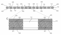
- FIG. 1 shows a plan view of a heat dissipating sheet according to a first embodiment of the present invention and an enlarged view of a portion B thereof.
- FIG. 2 shows a cross-sectional view of the heat dissipation sheet of FIG. 1 taken along the line AA, an enlarged view of part C thereof, and an enlarged view of part D thereof, respectively.
- the heat-dissipating sheet 1 is a sheet with excellent heat conductivity that conducts heat from a heat source to a member on the cooling side to enable heat dissipation from the heat source.
- a "heat radiation sheet” may also be referred to as a "thermally conductive sheet”.
- the heat dissipation sheet 1 is configured such that one surface 11 in the thickness direction of the rubber-like elastic body 10 is in contact with a heat source, and the other surface 12 in the thickness direction is in contact with a member on the cooling side. It is a sheet that is used by being placed between members on the cooling side.
- the heat-dissipating sheet 1 includes a sheet-like rubber-like elastic body 10 and carbon fibers 20 embedded and oriented obliquely with respect to the thickness direction of the rubber-like elastic body 10 (vertical direction in FIG. 2). .
- the surfaces 11 and 12 are the widest surfaces of the rubber-like elastic body 10, and mean the surfaces of the rubber-like elastic body 10 that are visible in a plan view.
- the surface 11 means "the surface on the front side”.
- Surface 12 means "back side”.
- the carbon fiber 20 is an example of an elongated thermally conductive filler.
- the thermally conductive filler is superior in thermal conductivity to the rubber-like elastic body 10 .
- the rubber-like elastic body 10 has at least one hole 14 oriented obliquely with respect to its thickness direction (vertical direction in FIG. 2). Both ends 21 and 22 of the carbon fiber 20 are exposed to the surfaces 11 and 12 of the rubber-like elastic body 10 .
- the pores 14 are preferably more than 0% and less than 80%, more preferably more than 20% and less than 60%, with respect to the area of the surface 11 or the surface 12 of the rubber-like elastic body 10 . This also applies to the second embodiment, which will be described later.
- the inclination angle of the pores 14 with respect to the surface 11 or the surface 12 is preferably greater than 0° and less than 80°, more preferably greater than 20° and less than 50°. This also applies to the second embodiment, which will be described later.
- the heat-dissipating sheet 1 is a member in which a plurality of rubber-like elastic bodies 10 are laminated to form a single sheet in plan view.
- silicone rubber 30 obtained by curing uncured liquid rubber is preferably arranged between a plurality of rubber-like elastic bodies 10. As shown in FIG. The silicone rubber 30 is preferably arranged between the rubber-like elastic bodies 10 and the holes 14 in the thickness direction of the heat-dissipating sheet 1 (vertical direction in FIG. 2) (enlarged view of part C in FIG. 2). ).
- the uncured liquid rubber serves as an adhesive that bonds the rubber-like elastic bodies 10 together.
- the rubber-like elastic body 10 is not particularly limited and can be appropriately selected according to the performance required for the heat dissipation sheet.
- examples thereof include thermosetting resins and thermoplastic resins.
- Thermosetting resins include, for example, elastomeric thermosetting resins such as silicone rubber, silicone resin, polyurethane resin, and epoxy resin.
- thermoplastic resins include synthetic rubbers, polyethylene resins, polyurethane resins, ABS resins, elastomeric thermoplastic resins such as soft vinyl chloride resins, and the like. These may be used individually by 1 type, and may use 2 or more types together.
- the rubber-like elastic body 10 may contain the resin material as described above and a filler having higher thermal conductivity than the resin material. As a result, the rubber-like elastic body 10 has a higher thermal conductivity than the rubber-like elastic body 10 made of only a resin material, so that the thermal conductivity from the heat source to the member on the cooling side can be further increased.
- fillers examples include aluminum oxide (Al 2 O 3 ), aluminum nitride (AlN), cubic boron nitride (cBN), hexagonal boron nitride (hBN), zinc oxide, silicon carbide, aluminum hydroxide, and diamond. Particulate, fibrous, plate-like or needle-like fillers can be selected. A filler with high insulating properties is more preferred.
- the carbon fiber 20 as an example of an elongated thermally conductive filler preferably has an angle ⁇ 1 of greater than 45° and 85° with respect to the surfaces 11 and 12 of the rubber-like elastic body 10 . It is embedded in the rubber-like elastic body 10 oriented so as to be smaller than °.
- angle ⁇ 1 By making the angle ⁇ 1 larger than 45° in the heat dissipation sheet 1, it is possible to suppress a decrease in thermal conductivity in the thickness direction. Further, in the heat-dissipating sheet 1, by setting the angle ⁇ 1 to be smaller than 85°, it is possible to suppress an increase in hardness.
- ⁇ 1 may be an angle larger than 0° and 45° or less.
- Both ends 21 and 22 of carbon fiber 20 are preferably flush with surfaces 11 and 12 of rubber-like elastic body 10, respectively, and do not protrude or dent greatly from surfaces 11 and 12, respectively.
- the diameter ⁇ 1 of both ends 21 and 22 exposed on the surfaces 11 and 12 of the rubber-like elastic body 10 is preferably larger than the diameter ⁇ 2 of the region 23 embedded in the rubber-like elastic body 10.
- the magnitude of ⁇ 1 with respect to ⁇ 2 is preferably 1 ⁇ 1/ ⁇ 2 ⁇ 2, more preferably 1.5 ⁇ 1/ ⁇ 2 ⁇ 2.
- both ends 21 and 22 of the carbon fibers 20 are larger than the diameter ⁇ 2 of the other region 23, for example, the external force in the direction of pulling out the carbon fibers 20 (orientation direction of the carbon fibers 20) is Even if it is applied, it is possible to prevent the carbon fibers 20 from being pulled out from the rubber-like elastic body 10 .
- both ends 21 and 22 of the carbon fibers 20 having a diameter ⁇ 1 are in contact with the heat source or the cold-side member, so the contact area between the carbon fibers 20 and the heat source or the cooling-side member increases. , can increase the thermal conductivity.
- the orientation angle ⁇ 1 of the carbon fibers 20 is not limited to the above range as long as the carbon fibers 20 are oriented obliquely with respect to the thickness direction of the rubber-like elastic body 10 .
- the carbon fibers 20 are not particularly limited, they are preferably anisotropic pitch-based carbon fibers. However, the carbon fibers 20 are not limited to anisotropic pitch-based carbon fibers. or a mixture of two or more of these carbon fibers.
- the fiber length of the carbon fibers 20 is preferably 0.002 mm to 10 mm, more preferably 0.005 mm to 7.5 mm.
- the fiber diameter of the carbon fibers 20 is preferably 1 ⁇ m to 50 ⁇ m, more preferably 5 to 25 ⁇ m.
- Silicone rubber 30 is hardened uncured liquid rubber and has low fluidity or is in a solid state.
- Uncured liquid rubber is a highly flowable rubber that can be cured by any desired method. Examples of curing methods for the uncured liquid rubber include heating, light irradiation, electron beam irradiation, and curing with a catalyst or curing agent.
- uncured liquid rubber examples include liquid silicone rubber, liquid natural rubber, liquid isoprene rubber, liquid butadiene rubber, liquid styrene-butadiene rubber, liquid butyl rubber, liquid nitrile rubber, liquid ethylene-propylene rubber, liquid chloroprene rubber, liquid chloroprene rubber, Examples include sulfonated polyethylene rubber, liquid urethane rubber, and liquid fluororubber.
- liquid silicone rubbers are preferred because they are less susceptible to dimensional change and warpage after curing, have a small compression set, and have high heat resistance.
- the liquid silicone rubber may be either condensation type or addition type.
- the heat-dissipating sheet 1 preferably has a plurality of holes 14 oriented obliquely with respect to the thickness direction of the rubber-like elastic body 10 (vertical direction in FIG. 2).
- the holes 14 are preferably through holes penetrating from one surface 11 to the other surface 12 of the rubber-like elastic body 10 in the thickness direction.
- heat dissipation sheet 1 has a plurality of holes 14 arranged at predetermined intervals on surfaces 11 and 12 .
- the number, arrangement, form, and the like of the holes 14 are not particularly limited, and are preferably designed appropriately according to the performance required of the heat dissipation sheet.
- the holes 14 do not have to penetrate from one surface 11 to the other surface 12 .
- the holes 14 are provided substantially parallel to the orientation direction of the carbon fibers 20 (see enlarged view of part C in FIG. 2). However, as long as the pores 14 are oriented obliquely with respect to the thickness direction of the rubber-like elastic body 10, they do not have to be arranged parallel to the orientation direction of the carbon fibers 20.
- FIG. The heat-dissipating sheet 1 configured in this way can suppress an increase in hardness due to the holes 14 oriented obliquely with respect to the thickness direction. Moreover, the heat dissipation sheet 1 is compressed in the thickness direction between the heat source and the member on the cooling side. Since the heat dissipation sheet 1 has the holes 14 , it is possible to reduce the stress on the carbon fibers 20 and suppress the breakage of the carbon fibers 20 even when deformed by the compression.
- the heat-dissipating sheet 1 preferably has surfaces 11 and 12 perpendicular to its thickness direction (vertical direction in FIG. 2) with an arithmetic mean roughness Ra of 1.0 ⁇ m or more and 1.8 ⁇ m or less. Moreover, the heat dissipation sheet 1 preferably has a ten-point average roughness Rz of the surfaces 11 and 12 of 7.7 or more and 18 ⁇ m or less.
- the arithmetic mean roughness Ra is a value measured according to JIS B 0601-2001.
- the ten-point average roughness Rz is a value measured according to JIS B 0601-1994.
- the surfaces 11 and 12 perpendicular to the thickness direction of the heat dissipating sheet 1 are flattened, so that the heat source and the carbon fibers 20 can more reliably contact each other. It is possible to increase the thermal conductivity.
- the manufacturing method of the heat-dissipating sheet 1 includes a step of ejecting a curable rubber composition containing carbon fibers 20 onto the plane of the planar body along a first predetermined direction in a plurality of rows, and The resulting curable rubber composition is molded into a sheet and cured to form a carbon-containing sheet (filler-containing sheet Example), a plurality of carbon-containing sheets are laminated with uncured liquid rubber arranged between the carbon-containing sheets, the uncured liquid rubber is cured, and the orientation of the carbon fibers 20 is oriented.
- a carbon-containing sheet iller-containing sheet Example
- It includes a stacking step of forming blocks that are aligned and stacked, and a cutting step of cutting the blocks into sheets in a direction oblique to the direction in which the carbon fibers 20 are oriented.
- a stacking step of forming blocks that are aligned and stacked and a cutting step of cutting the blocks into sheets in a direction oblique to the direction in which the carbon fibers 20 are oriented.
- FIG. 3 shows an example of the flow of main steps of the method for manufacturing a heat dissipation sheet according to the first embodiment of the present invention.
- FIG. 4 shows the state of each step of the manufacturing method of FIG. 3 in plan view and cross-sectional view.
- FIG. 5 shows the state of each step following FIG. 4 in a cross-sectional view.
- FIG. 6 shows the state of each step following FIG. 5 in plan view.
- FIG. 7 shows the state of each step following FIG. 6 in a cross-sectional view.
- FIG. 8 shows a perspective view of each step following FIG.
- the carbon fibers 20 are exaggeratedly drawn for explanation of the manufacturing process.
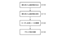
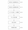
- the heat dissipation sheet 1 can be manufactured through a discharge process (S100), a molding process (S110), a lamination process (S120), and a cutting process (S130). S100 to S130 will be described in detail below with reference to FIGS.
- Ejection step (S100) In this step, the curable rubber composition 70 containing the carbon fibers 20 is placed on the plane of a film (an example of a plane body) 72 along the first predetermined direction D1 (vertical direction in FIG. 4A). This is the step of discharging (see FIG. 4).
- the ejection step (S100) includes a recess 41 (see the EE line cross-sectional view of FIG. See), it is preferable to discharge the curable rubber composition 70 onto the film 72 while the film 72 is placed thereon.
- the curable rubber composition 70 linearly discharged along the first predetermined direction D1 is spread in a direction perpendicular to the first predetermined direction D1 (horizontal direction in FIG. 4A). A plurality of lines are discharged so as to line up (see FIG. 4(a)), and a sheet-like curable rubber composition 70 is formed on the film 72 (see FIG. 4(b)).
- the curable rubber composition 70 is a composition that becomes the rubber-like elastic body 10 after curing.
- the carbon fibers 20 can be oriented along the first predetermined direction D1 by discharging the curable rubber composition 70 containing the carbon fibers 20 along the first predetermined direction D1. .
- the film 72 is preferably a film made of resin.
- resins include polyethylene terephthalate (PET), polyethylene naphthalate, polyethylene isophthalate, polybutylene terephthalate, polyacetate, polycarbonate, polyphenylene sulfide, polyamide, polyvinyl chloride, and polyvinylidene chloride.
- PET polyethylene terephthalate
- polyethylene naphthalate polyethylene isophthalate
- polybutylene terephthalate polyacetate
- polycarbonate polyphenylene sulfide
- polyamide polyvinyl chloride
- polyvinylidene chloride polyvinylidene chloride
- the curable rubber composition 70 discharged onto the film 72 is formed into a sheet and cured, and the carbon fibers 20 are oriented in the first predetermined direction D1 and at least one sheet along the second predetermined direction D2.
- the second predetermined direction D2 is the same direction as the first predetermined direction D1 (the depth direction in FIG. 5).
- the first predetermined direction deviates from the second predetermined direction by preferably within 20 degrees, more preferably within 10 degrees, and even more preferably within 5 degrees.
- the carbon-containing sheet 76 includes a plurality of recesses 78 at predetermined intervals in a direction perpendicular to the second predetermined direction D2 (horizontal direction in FIG. 5). More specifically, first, a plane of a film (an example of a plane body) 74 is placed on the curable rubber composition 70 discharged onto the film 72 . Film 74 is preferably constructed of the same material as film 72 described above. Next, an upper mold 50 constituting the mold 60 is prepared, placed on the recess 41 side of the lower mold 40, and the lower mold 40 and the upper mold 50 are closed (FIGS. 5(c) and (d)). ).
- the upper mold 50 has a recess 51 on the surface facing the recess 41 of the lower mold 40 .
- the recess 51 has, on its inner bottom surface, an unevenness 52 on which the recess 78 can be transferred.
- the mold 60 is clamped, it is heated to mold the curable rubber composition 70 (see FIG. 5(e)).
- the curable rubber composition 70 is cured to form the rubbery elastic body 10 containing the carbon fibers 20 .
- recesses 78 are formed by transferring the unevenness 52 .
- the mold 60 is opened and the films 72 and 74 are peeled off to form a carbon-containing sheet 76 (see FIG. 5(f)).
- the carbon-containing sheet 76 is a sheet containing the rubber-like elastic body 10 and the carbon fibers 20 oriented along the first predetermined direction D1 (the depth direction of the paper surface in FIG. 5(f)). Also, the carbon-containing sheet 76 is a sheet provided with a plurality of recesses 78 at predetermined intervals in a direction perpendicular to the second predetermined direction D2 (horizontal direction in FIG. 5) (see FIG. 6(g)).
- two types of carbon-containing sheets 80, 82 are cut out from the carbon-containing sheet 76 (see FIG. 6(g)).
- the carbon-containing sheet 80 and the carbon-containing sheet 82 are carbon-containing sheets having different positions of the concave portions 78 in the direction perpendicular to the second predetermined direction D2 (horizontal direction in FIG. 6).
- the carbon-containing sheets 80 and 82 are sheets containing the carbon fibers 20 oriented along the first predetermined direction D1 (vertical direction in FIG. 6).
- the forming step (S110) preferably includes forming the carbon-containing sheet 76 in the second predetermined direction so that the positions of the concave portions 78 are different in the direction perpendicular to the second predetermined direction D2 (horizontal direction in FIG. 6).
- Carbon-containing sheets 80 and 82 are formed by cutting along D2 (the vertical direction in FIG. 6).
- the carbon-containing sheet 80 and the carbon-containing sheet 82 are sheets of the same size, but they may be sheets of different sizes.
- the method of cutting out the carbon-containing sheets 80 and 82 from the carbon-containing sheet 76 is not particularly limited as long as it is a method capable of forming two types of carbon-containing sheets 80 and 82 .
- Lamination step In this step, a plurality of carbon-containing sheets 80 and 82 are laminated with uncured liquid rubber 85 interposed between the carbon-containing sheets 80 and 82, and the uncured liquid rubber 85 is cured to form the carbon fibers 20.
- This is the step of forming block bodies 90 laminated with aligned orientation (see FIG. 7).
- the positions of the concave portions 78 of the carbon-containing sheets 80 and 82 are different in the thickness direction (vertical direction in FIG. 7) of the carbon-containing sheets 80 and 82.
- the uncured liquid rubber 85 is placed between the carbon-containing sheets 80 and 82, and the carbon-containing sheet 82 is stacked (see FIG. 7(h)). At this time, the two carbon-containing sheets 80 and 82 are stacked such that the orientation directions D1 of the carbon fibers 20 contained in the two carbon-containing sheets 80 and 82 are the same. overlap.
- the uncured liquid rubber 85 is preferably applied to the bottom surface of the carbon-containing sheet 82 (that is, the smooth surface). This is because it is easier to apply the uncured liquid rubber 85 to the garbon-containing sheet 82 in a thin and uniform thickness.
- the two carbon-containing sheets 80 and 82 stacked with the uncured liquid rubber 80 interposed therebetween are arranged so that the recesses 78 are positioned at different positions in the thickness direction of the carbon-containing sheets 80 and 82 .
- the carbon-containing sheets 80, 82 are stacked. That is, in the stacking step (S120), the recessed portions 78 of the carbon-containing sheet 80 and the recessed portions 78 of the carbon-containing sheet 82 are not arranged on the same straight line along the thickness direction (vertical direction in FIG. 7). Two carbon-containing sheets 80, 82 are stacked (see FIGS. 7(h) and (i)).
- the uncured liquid rubber 85 becomes the silicone rubber 30 after curing, and is preferably liquid silicone rubber. Further, in this embodiment, the uncured liquid rubber 85 plays a role of an adhesive that bonds the carbon-containing sheets 80 and 82 together. Then, the uncured liquid rubber 85 is cured while the plurality of carbon-containing sheets 80 and 82 are laminated to form a block body 90 (see FIG. 7(j)).
- the block body 90 is a laminate in which the orientation directions D1 of the carbon fibers 20 contained in the plurality of carbon-containing sheets 80 and 82 are the same (see FIG. 8(k)).
- the uncured liquid rubber 85 preferably has a hardness equal to or lower than that of the carbon-containing sheets 80 and 82 after curing. This is because the increase in hardness of the block body 90 can be suppressed and flexibility can be imparted.
- the stacking step (S120) may be performed by stacking the carbon-containing sheets 82 and performing a curing process such as heating (or cooling).
- This step is a step of cutting the block body 90 into a sheet in a direction oblique to the orientation direction D1 of the carbon fibers 20 (see FIG. 8). More specifically, it is cut into a predetermined thickness at an angle ⁇ 2 larger than 45° and smaller than 85° with respect to the orientation direction D1 of the carbon fibers 20 (see FIG. 8(k)).
- the predetermined thickness is preferably 0.01 mm to 10 mm, more preferably 0.05 mm to 5 mm.
- the cutting means is not particularly limited as long as it can cut into a predetermined thickness, such as a known cutter or slicer, but it is preferable to slice using a rotating blade as the cutting means. .
- the diameter ⁇ 1 of the cut surfaces 21 and 22 is compared with the diameter ⁇ 2 of the region 23 embedded in the rubber-like elastic body 10. It can be large (see Figures 1 and 2).
- FIGS. 8(l) and 8(m) show the figure seen from the arrow F direction in FIG. 8(l).
- Carbon fibers 20 and holes 14 are embedded obliquely with respect to the thickness direction (the vertical direction in FIG. 8(m)) of the heat dissipation sheet 1 manufactured in this manner (see FIG. 8(m). reference).
- both ends 21 and 22 of the carbon fibers 20 are exposed on the cut surfaces (that is, the surfaces 11 and 12 of the rubber-like elastic body 10).
- the diameter ⁇ 1 of both end portions 21 and 22 exposed on the cut surfaces 11 and 12 of the carbon fiber 20 is larger than the diameter ⁇ 2 of the region 23 embedded in the rubber-like elastic body 10 .
- the heat dissipation sheet 1 manufactured in this way the contact area between the carbon fibers 20 and the member on the heat source or the cooling side is increased, and the thermal conductivity can be improved. Further, according to the heat dissipation sheet 1, for example, even when an external force is applied in the direction of pulling out the carbon fibers 20 (orientation direction Do of the carbon fibers 20), the carbon fibers 20 are pulled out of the rubber-like elastic body 10. can be suppressed. In addition, since the heat-dissipating sheet 1 is cut so as to reduce the surface roughness in the cutting step (S130), the cut surface becomes flat, and the heat source and the carbon fibers 20 can more reliably contact each other. Therefore, thermal conductivity can be further increased.
- the heat dissipation sheet 1 since the heat dissipation sheet 1 has high thermal conductivity as described above, it is not necessary to increase the filling rate of the carbon fibers 20 in order to increase the thermal conductivity. Therefore, the heat dissipation sheet 1 can suppress an increase in hardness due to an increase in the filling rate of the carbon fibers 20, and can realize low hardness and high thermal conductivity.
- the heat dissipation sheet 1 since the heat dissipation sheet 1 is provided with the holes 14 oriented obliquely to the thickness direction, the hardness of the heat dissipation sheet 1 is suppressed from increasing, and even when the heat dissipation sheet 1 is deformed due to compression in the thickness direction, the carbon fibers 20 stress can be reduced, and breakage of the carbon fibers 20 can be suppressed.
- At least one of the surfaces 11 and 12 perpendicular to the thickness direction of the heat dissipation sheet 1 may be coated with a resin.
- the resin used for this coating is not particularly limited, and examples thereof include thermosetting resins and thermoplastic resins similar to the material of the rubber-like elastic body 10 described above. Further, like the rubber-like elastic body 10, it may contain a resin material as described above and a filler having higher thermal conductivity than the resin material. As the filler, the same filler as the rubber-like elastic body 10 can be used. According to the heat-dissipating sheet 1 configured in this way, it is possible to further prevent the carbon fibers 20 from falling off from the rubber-like elastic body 10 due to the coating on the surfaces 11 and 12 .
- the thermally conductive sheet 1 can reduce deterioration in thermal conductivity due to coating by including a filler having high thermal conductivity in the resin material used for coating.
- the heat dissipation sheet 1 can be manufactured by coating the surfaces 11, 12 after the cutting step (S130).
- the carbon-containing sheet 76 is formed with the concave portions 78 by molding with the mold 60, but the concave portions 78 may be formed by other methods such as cutting and etching.
- the molding step (S110) instead of the upper mold 50, an upper mold that does not have the unevenness 52 on the inner bottom surface of the recess 51 is used to form the carbon-containing sheet 76 that does not have the recess 78.
- the recesses 78 may be formed in the carbon-containing sheet 76 by using a method such as cutting or etching.
- the carbon-containing sheet 76 was cut out to form the two types of carbon-containing sheets 80 and 82.
- sheet 82 may be formed.
- the two types of carbon-containing sheets 80 and 82 may be formed by the same method as that for forming the carbon-containing sheet 76 in the molding process.
- the carbon-containing sheets 80 and 82 are subjected to a technique such as cutting or etching. may be used to form the recess 78 .
- the plurality of carbon-containing sheets 80, 82 are stacked such that the positions of the concave portions 78 of the carbon-containing sheets 80, 82 are the same in the thickness direction of the carbon-containing sheets 80, 82.
- a trimming process for trimming the excess area of the carbon-containing sheet 76 may be performed.
- FIG. 9 shows a plan view of a heat dissipation sheet according to the second embodiment of the present invention and an enlarged view of part B thereof.
- FIG. 10 shows a cross-sectional view of the heat dissipation sheet of FIG. 9 taken along line AA, an enlarged view of part C thereof, and an enlarged view of part D thereof, respectively.
- the heat dissipation sheet 1 includes a sheet-like rubber-like elastic body 10 and carbon fibers 20 embedded in the rubber-like elastic body 10 and oriented obliquely with respect to the thickness direction of the rubber-like elastic body 10 .
- the rubber-like elastic body 10 is a single non-laminated sheet.
- the rubber-like elastic body 10 has at least one pore 14 oriented in its thickness direction. Both ends of the carbon fibers 20 are exposed on the surface of the rubber-like elastic body 10 .
- the holes 14 are through holes that connect the surfaces 11 and 12 of the rubber-like elastic body 10 in the thickness direction.
- the holes 14 are through holes parallel to the thickness direction of the rubber-like elastic body 10 .
- the carbon fibers 20 exist in the rubber-like elastic body 10 at an angle of ⁇ 1 (acute angle) with respect to the surface 12 of the rubber-like elastic body 10 .
- the diameter ⁇ 1 of the carbon fibers 20 exposed on the surfaces 11 and 12 of the rubber-like elastic body 10 is preferably larger than the diameter ⁇ 2 of the part embedded in the rubber-like elastic body 10 .
- the magnitude of ⁇ 1 with respect to ⁇ 2 is here 1 ⁇ 1/ ⁇ 2 ⁇ 2, more preferably 1.1 ⁇ 1/ ⁇ 2 ⁇ 1.5.
- the carbon fibers 20 are in contact with the heat source or the cooling member at the portion having the diameter ⁇ 1.
- the orientation angle ⁇ 1 of the carbon fibers 20 is not limited to the above range as long as the carbon fibers 20 are oriented obliquely with respect to the thickness direction of the rubber-like elastic body 10 .
- the holes 14 exhibit the effect of facilitating the deformation of the heat dissipation sheet 1, and also exhibit the effect of retaining lubricant, as will be described later.
- the retention effect of the lubricant will be described later in detail.
- FIG. 11 shows a plan view of a first modification of the heat dissipation sheet of FIG.
- the heat-dissipating sheet 1 according to the first modification is a laminated sheet of a plurality of sheets, like the heat-dissipating sheet 1 according to the first embodiment.
- silicone rubber 30, which is obtained by curing uncured liquid rubber, is preferably arranged between a plurality of rubber-like elastic bodies 10. As shown in FIG. In other words, the silicone rubber 30 is arranged between one hole 14 and another hole 14 .
- the silicone rubber 30 is preferably arranged between the rubber-like elastic bodies 10 and the holes 14 in the thickness direction of the heat dissipation sheet 1 .
- the uncured liquid rubber serves as an adhesive that bonds the rubber-like elastic bodies 10 together.
- FIG. 12 is a view showing a second modification of the heat dissipation sheet of FIG. 9, showing a cross-sectional view similar to the cross-sectional view taken along line AA of FIG. 9 and an enlarged view of part C thereof.
- the heat dissipation sheet 1 according to the second modification includes at least one hole 14 oriented obliquely with respect to the thickness direction of the rubber-like elastic body 10, as in the first embodiment.
- the angle at which the holes 14 are tilted with respect to the surface 12 is the same ⁇ 1 (acute angle) as the angle at which the carbon fibers 20 are tilted with respect to the surface 12 .
- the inclination angle of the holes 14 and the inclination angle of the carbon fibers 20 may be different.
- FIG. 13 is a view showing a third modification of the heat dissipation sheet of FIG. 9, showing a cross-sectional view similar to the cross-sectional view taken along line AA of FIG. 9 and an enlarged view of part C thereof.
- the heat dissipation sheet 1 according to the third modification has a lubricant coating layer 45 on at least one of the surfaces 11 and 12 of the rubber-like elastic body 10 .
- the heat dissipation sheet 1 has coat layers 45 on both surfaces 11 and 12 .
- the coat layer 45 may be provided only on one of the surfaces 11 and 12 .
- the coat layer 45 is provided in the region other than the pores 14 of the rubber-like elastic body 10 .
- part of the lubricant forming the coating layer 45 may exist in the pores 14 . In that case, it is preferable not to fill all the holes 14 with the lubricant.
- the lubricant in the coat layer 45 and the pores 14 has a high viscosity such that it does not flow easily from the rubber-like elastic body 10 , but is preferably softer than the rubber-like elastic body 10 .
- the coat layer 45 is mainly composed of grease as an example of a lubricant, and is a layer that has high viscosity and can retain its shape.
- Greases include, for example, modified silicone, silicone oil, and ester oil-based greases containing fillers with higher thermal conductivity than the base material.
- fillers with high thermal conductivity are aluminum oxide ( Al2O3 ), aluminum nitride ( AlN ), cubic boron nitride (cBN), hexagonal boron nitride (hBN), zinc oxide, silicon carbide, aluminum hydroxide. , particulate, fibrous, plate-like or needle-like fillers typified by diamond.
- a filler with high insulating properties is more preferred.
- the grease may use the base material alone.
- the coat layer 45 can prevent the carbon fibers 20 from falling off from the rubber-like elastic body 10 .
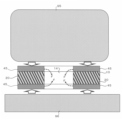
- FIG. 14 shows a cross-sectional view of a situation in which the heat dissipation sheet according to the third modification is sandwiched between the cooling member and the heat source.
- FIG. 15 shows a cross-sectional view of a situation in which the cooling member and the heat source completely sandwich the heat radiation sheet, proceeding further from the situation in FIG.
- cooling member is broadly interpreted to include, in addition to positively cooling members, members that are lower in temperature than the heat source and are capable of dissipating heat from the heat source.
- the heat dissipation sheet 1 according to the third modification is sandwiched between the cooling member 95 and the heat source 96, the coat layers 45 formed on both sides in the thickness direction of the rubber-like elastic body 10 are compressed, and the lubricant 45a is an empty space. Go into hole 14 (see arrow F). In FIG. 15, the cavity 14 is filled with a lubricant 45a. However, the holes 14 may not be filled with the lubricant 45a, and there may be spaces (existence of air) in the holes 14.
- FIG. 16 shows an example (16A) in which a lubricant is supplied to the surface of a conventional hole-free heat radiation sheet and a heat sink, which is an example of a cooling member, is brought into contact with the heat radiation sheet.
- a cross-sectional view is shown for comparison with an example (16B) in which a heat sink is brought into contact with a heat radiation sheet by supplying an agent. Note that in FIG. 16, the heat source is omitted from the surface of the heat dissipation sheet opposite to the heat sink.
- FIG. 17 shows a plan view of a heat dissipation sheet according to a fourth modification and a cross-sectional view of the plan view taken along the line AA.
- the coating layer 45 of the lubricant 45a is provided on both the front surface and the back surface of the rubber-like elastic body 10. , and the holes 14 do not have the lubricant 45a.
- the number of holes 14 and the shape in plan view are different from those of the third modification.
- the holes 14 have a rectangular or square shape in plan view, and are provided with a total of 80 holes 14 of 10 columns ⁇ 8 rows.
- the rubber-like elastic body 10 When the heat dissipation sheet 1 is sandwiched between the heat source and the cooling member in the thickness direction, the rubber-like elastic body 10 is compressed by the pressure applied in the thickness direction, and the lubricant constituting the coat layer 45 is applied. 45a enters the hole 45a. As a result, the risk of the lubricant 45a overflowing to the outside of the heat dissipation sheet 1 can be reduced.
- FIG. 18 shows a plan view of a heat dissipation sheet according to the fifth example and a cross-sectional view taken along the line AA of the plan view.
- the heat dissipation sheet 1 according to the fifth modification has rubber-like elastic bodies 10 similar to the heat dissipation sheet 1 according to the fourth modification. That is, the number and shape of the holes 14 in the fifth modification are the same as in the fourth modification.
- the heat-dissipating sheet 1 according to the fifth modification has lubricant 45 a in some of the holes 14 among all the holes 14 . More specifically, the pores 14 located at the in-plane outermost periphery of the rubber-like elastic body 10 do not contain the lubricant 45a, and the pores in the region inside the plane from the pores 14 located at the in-plane outermost periphery. 14 contains a lubricant 45a.
- Neither the front surface nor the back surface of the rubber-like elastic body 10 is provided with the coat layer 45 .
- the rubber-like elastic body 10 is compressed by the pressure applied in the thickness direction, and the lubricant 45a in the holes 14 is compressed. overflows from the holes 45 a to the front and back surfaces of the rubber-like elastic body 10 .
- the holes 14 located at the in-plane outermost periphery contribute to suppressing the overflow of the lubricant 45 a to the outside of the heat dissipation sheet 1 . Therefore, the risk of the lubricant 45a overflowing to the outside of the heat dissipation sheet 1 can be further reduced.
- FIG. 19 shows a plan view of a heat dissipation sheet according to the sixth modification and a cross-sectional view of the plan view taken along the line AA.
- the heat dissipation sheet 1 according to the sixth modification has rubber-like elastic bodies 10 similar to the heat dissipation sheet 1 according to the fourth modification. That is, the number and shape of the holes 14 in the sixth modification are the same as in the fourth modification.
- the heat dissipation sheet 1 according to the sixth modification has the lubricant 45 a in some of the holes 14 among all the holes 14 . More specifically, the pores 14 located on the outermost periphery in the plane of the rubber-like elastic body 10 do not contain the lubricant 45a, and the lubricant 45a is contained in a region inside the surface of the pores 14 located on the outermost periphery in the plane. 45a.
- a lubricant 45a is filled in the holes 14 in the region on the inner side of the plane.
- a coat layer 45 of a lubricant 45a is provided on the inner surface area other than the holes 14, that is, on the front side surface and the back side surface of the rubber-like elastic body 10.
- the holes 14 positioned at the in-plane outermost periphery contribute to suppressing the lubricant 45a from overflowing to the outside of the heat dissipation sheet 1, as in the fifth modification. Therefore, the risk of the lubricant 45a overflowing to the outside of the heat dissipation sheet 1 can be further reduced.
- FIG. 20 shows a plan view of a heat dissipation sheet according to the seventh modification and a cross-sectional view of the plan view taken along the line AA.
- the heat dissipation sheet 1 according to the seventh modification has rubber-like elastic bodies 10 similar to the heat dissipation sheet 1 according to the fourth modification. That is, the number and shape of the holes 14 in the seventh modified example are the same as in the fourth modified example.
- the pores 14 located on the in-plane outermost periphery of the rubber-like elastic body 10 do not contain the lubricant 45a, and the pores 14 located on the in-plane outermost periphery do not contain the lubricant 45a. It has a lubricant 45a in the inner and inner regions.
- the seventh modification differs from the sixth modification in that the lubricant 45a in the pores 14 in the in-plane inner region does not fill the entire volume of the pores 14, but rather extends along the length of the pores 14. It is a point that does not satisfy a part of That is, in the seventh modified example, spaces 105 without lubricant 45a exist in the longitudinal direction of holes 14 containing lubricant 45a. Even with such a heat dissipation sheet 1, the same effects as in the sixth modification can be exhibited. A wall that divides the air hole 14 into two may be formed instead of the space 105 .
- the formation of the holes 14 in the heat dissipation sheet 1 may be performed after S130 instead of before S120.
- FIG. 21 shows the flow of the manufacturing method for forming holes after the step of cutting the block body.
- the manufacturing method of the heat dissipation sheet shown in FIG. 21 includes: A discharging step (S100) of discharging a curable rubber composition 70 containing carbon fibers 20 in a plurality of rows along a first predetermined direction D1 on the plane of a film (an example of a plane body) 72; a forming step (S110) of forming a carbon-containing sheet 76 in which the curable rubber composition 70 discharged onto a flat surface is formed into a sheet and cured to form a carbon-containing sheet 76 in which the carbon fibers 20 are oriented in the first predetermined direction D1; A block in which a plurality of carbon-containing sheets 76 are laminated with uncured liquid rubber 85 arranged between the carbon-containing sheets 76, the uncured liquid rubber 85 is cured, and the orientation of the carbon fibers 20 is aligned.
- the sheet may be cut at an angle larger than 45° and smaller than 85° with respect to the orientation direction of the carbon fibers 20.
- the molding step (S110) in the flow of FIG. 21 does not form the concave portion 78 during molding. That is, in the flow of FIG. 21, the holes 14 are not formed by the concave portions 78, and the holes 14 are formed after the cutting step (S130) (hole forming step: S140).
- the manufacturing method other than forming the recesses 78 during molding and forming the holes 14 after cutting has already been explained with reference to FIGS.
- the flow of FIG. 21 can also be used when manufacturing the heat dissipation sheet 1 of FIGS.
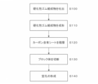
- FIG. 22 shows the flow of the manufacturing method for supplying the lubricant to the rubber-like elastic body after the pore forming process.
- FIG. 22 shows an exemplary manufacturing method of the heat dissipation sheet 1 according to the second embodiment.
- the lubricant 45a is supplied to at least one of the front and back surfaces of the rubber-like elastic body 10 and/or the inside of the holes 14 after the hole forming step (S140).
- the agent supply step (S150) is performed.
- the heat-dissipating sheets 1 according to the third to seventh modifications of the second embodiment can be manufactured by a manufacturing method including a lubricant supply step (S150).
- the lubricant supplying step ( S ⁇ b>150 ) is broadly interpreted as including either one or both of the step of filling the pores 14 with the lubricant 45 a and the step of forming the coat layer 45 .
- the coating layer 45 is broadly defined so as to include not only the layer obtained by supplying the lubricant 45a to the surfaces 11 and 12 of the rubber-like elastic body 10, but also the layer in which the pores 14 are filled with the lubricant 45a. is interpreted as Before the hole forming step (S140), the lubricant 45a is supplied to at least one of the front and back surfaces of the rubber-like elastic body 10 and/or the inside of the holes 14. Also good. For example, when manufacturing the heat dissipation sheet 1 according to the fourth modification of the second embodiment, after the cutting step (S130), the lubricant supplying step (S150) is performed, and then the hole forming step (S140). may be carried out to remove the holes 14 and the lubricant 45a at the positions.
- FIG. 23 shows a photograph of a heat dissipation sheet according to the first modified example of the second embodiment.
- the two heat dissipation sheets 1 shown in FIG. 23 are the same.
- the reason why the entire sheet is black is that the carbon fibers 20 are included in the sheet.
- FIG. 24 shows a modification of the flow diagram of FIG.
- the flow diagram of FIG. 24 excludes the pore forming step (S140) from the flow diagram of FIG. In this case, the holes 14 are formed in a process similar to the molding process (S110) in FIG. Therefore, the lubricant 45a may be supplied to the rubber-like elastic body 10 immediately after the cutting step (S130).
- the heat dissipation sheet 1 according to the third to seventh modifications of the second embodiment can be manufactured by the manufacturing method shown in FIG.
- the thermally conductive filler is not limited to the carbon fiber 20, and other whisker (needle)-like or fibrous elongated fillers may be used. Boron nitride, aluminum nitride, alumina and the like can be exemplified as the elongated filler.
- the filler-containing sheet may be a sheet containing the long filler other than the carbon fibers 20 .
- the shape of the surfaces of the holes 14 that open to the surfaces 11 and 12 is not limited to circular, elliptical, or quadrangular, and may be triangular, pentagonal, or polygonal.
- the heat-dissipating sheet 1 (see FIGS. 9 and 10) according to the second embodiment is manufactured by forming holes 14 after molding one sheet of rubber-like elastic body 10 in which carbon fibers 20 are oriented in one direction.
- the molding step (S110) in the flow of FIGS. 21 and 22 may be the second molding step (S110B).
- the components of the second embodiment and its various modifications may be combined with each other.
- the second modified example and the third modified example may be combined to form the holes 14 oblique to the thickness direction of the rubber-like elastic body 10 in the third modified example.
- the third modified example and the fourth modified example may be combined to form the holes 14 oblique to the thickness direction of the rubber-like elastic body 10 in the fourth modified example.
- the heat-dissipating sheet according to the present invention can be used, for example, in automobiles, industrial robots, power generators, PCs, various electronic devices such as household appliances, automobile batteries, household rechargeable and dischargeable batteries, and electronic devices such as PCs. It can be used as a battery for
Landscapes
- Engineering & Computer Science (AREA)
- Chemical & Material Sciences (AREA)
- Manufacturing & Machinery (AREA)
- Physics & Mathematics (AREA)
- Mechanical Engineering (AREA)
- Microelectronics & Electronic Packaging (AREA)
- Thermal Sciences (AREA)
- Chemical Kinetics & Catalysis (AREA)
- Polymers & Plastics (AREA)
- Organic Chemistry (AREA)
- Medicinal Chemistry (AREA)
- Health & Medical Sciences (AREA)
- Materials Engineering (AREA)
- Cooling Or The Like Of Semiconductors Or Solid State Devices (AREA)
- Compositions Of Macromolecular Compounds (AREA)
Priority Applications (4)
| Application Number | Priority Date | Filing Date | Title |
|---|---|---|---|
| EP22869980.7A EP4365939B1 (en) | 2021-09-15 | 2022-09-14 | Heat-dissipating sheet and method for manufacturing the same |
| US18/691,045 US20240381577A1 (en) | 2021-09-15 | 2022-09-14 | Heat-dissipating sheet and method for manufacturing the same |
| CN202280052913.0A CN117716490A (zh) | 2021-09-15 | 2022-09-14 | 散热片及其制造方法 |
| JP2023548474A JP7791894B2 (ja) | 2021-09-15 | 2022-09-14 | 放熱シートおよびその製造方法 |
Applications Claiming Priority (2)
| Application Number | Priority Date | Filing Date | Title |
|---|---|---|---|
| JP2021-149842 | 2021-09-15 | ||
| JP2021149842 | 2021-09-15 |
Publications (1)
| Publication Number | Publication Date |
|---|---|
| WO2023042833A1 true WO2023042833A1 (ja) | 2023-03-23 |
Family
ID=85602919
Family Applications (1)
| Application Number | Title | Priority Date | Filing Date |
|---|---|---|---|
| PCT/JP2022/034325 Ceased WO2023042833A1 (ja) | 2021-09-15 | 2022-09-14 | 放熱シートおよびその製造方法 |
Country Status (5)
| Country | Link |
|---|---|
| US (1) | US20240381577A1 (https=) |
| EP (1) | EP4365939B1 (https=) |
| JP (1) | JP7791894B2 (https=) |
| CN (1) | CN117716490A (https=) |
| WO (1) | WO2023042833A1 (https=) |
Cited By (1)
| Publication number | Priority date | Publication date | Assignee | Title |
|---|---|---|---|---|
| WO2025070441A1 (ja) * | 2023-09-27 | 2025-04-03 | バンドー化学株式会社 | 熱伝導性シート |
Citations (7)
| Publication number | Priority date | Publication date | Assignee | Title |
|---|---|---|---|---|
| JP2002088171A (ja) * | 2000-09-13 | 2002-03-27 | Polymatech Co Ltd | 熱伝導性シートおよびその製造方法ならびに放熱装置 |
| JP2007326976A (ja) * | 2006-06-08 | 2007-12-20 | Polymatech Co Ltd | 熱伝導性成形体及びその製造方法 |
| JP2010056299A (ja) | 2008-08-28 | 2010-03-11 | Teijin Ltd | 熱伝導ゴムシートの製造方法 |
| JP2013131564A (ja) * | 2011-12-20 | 2013-07-04 | Dexerials Corp | 熱伝導性シート、この熱伝導性シートを用いた半導体装置及び半導体装置の製造方法 |
| JP2015092534A (ja) * | 2013-09-30 | 2015-05-14 | 積水化学工業株式会社 | シリコーン熱伝導性シート |
| JP2015216387A (ja) * | 2010-06-17 | 2015-12-03 | デクセリアルズ株式会社 | 熱伝導性シート及びその製造方法 |
| WO2021090929A1 (ja) * | 2019-11-07 | 2021-05-14 | 帝人株式会社 | 放熱シート及びその製造方法 |
Family Cites Families (1)
| Publication number | Priority date | Publication date | Assignee | Title |
|---|---|---|---|---|
| JP5844767B2 (ja) * | 2013-04-11 | 2016-01-20 | 株式会社小松製作所 | 建設機械の表示装置および建設機械 |
-
2022
- 2022-09-14 JP JP2023548474A patent/JP7791894B2/ja active Active
- 2022-09-14 CN CN202280052913.0A patent/CN117716490A/zh active Pending
- 2022-09-14 US US18/691,045 patent/US20240381577A1/en active Pending
- 2022-09-14 WO PCT/JP2022/034325 patent/WO2023042833A1/ja not_active Ceased
- 2022-09-14 EP EP22869980.7A patent/EP4365939B1/en active Active
Patent Citations (7)
| Publication number | Priority date | Publication date | Assignee | Title |
|---|---|---|---|---|
| JP2002088171A (ja) * | 2000-09-13 | 2002-03-27 | Polymatech Co Ltd | 熱伝導性シートおよびその製造方法ならびに放熱装置 |
| JP2007326976A (ja) * | 2006-06-08 | 2007-12-20 | Polymatech Co Ltd | 熱伝導性成形体及びその製造方法 |
| JP2010056299A (ja) | 2008-08-28 | 2010-03-11 | Teijin Ltd | 熱伝導ゴムシートの製造方法 |
| JP2015216387A (ja) * | 2010-06-17 | 2015-12-03 | デクセリアルズ株式会社 | 熱伝導性シート及びその製造方法 |
| JP2013131564A (ja) * | 2011-12-20 | 2013-07-04 | Dexerials Corp | 熱伝導性シート、この熱伝導性シートを用いた半導体装置及び半導体装置の製造方法 |
| JP2015092534A (ja) * | 2013-09-30 | 2015-05-14 | 積水化学工業株式会社 | シリコーン熱伝導性シート |
| WO2021090929A1 (ja) * | 2019-11-07 | 2021-05-14 | 帝人株式会社 | 放熱シート及びその製造方法 |
Non-Patent Citations (1)
| Title |
|---|
| See also references of EP4365939A4 |
Cited By (2)
| Publication number | Priority date | Publication date | Assignee | Title |
|---|---|---|---|---|
| WO2025070441A1 (ja) * | 2023-09-27 | 2025-04-03 | バンドー化学株式会社 | 熱伝導性シート |
| JP7720491B1 (ja) * | 2023-09-27 | 2025-08-07 | バンドー化学株式会社 | 熱伝導性シート |
Also Published As
| Publication number | Publication date |
|---|---|
| EP4365939A4 (en) | 2024-11-06 |
| US20240381577A1 (en) | 2024-11-14 |
| EP4365939B1 (en) | 2026-03-18 |
| JP7791894B2 (ja) | 2025-12-24 |
| JPWO2023042833A1 (https=) | 2023-03-23 |
| CN117716490A (zh) | 2024-03-15 |
| EP4365939A1 (en) | 2024-05-08 |
Similar Documents
| Publication | Publication Date | Title |
|---|---|---|
| CN101625210B (zh) | 导热片复合体及其制造方法 | |
| CN103547441B (zh) | 高导热性/低热膨胀系数的复合物 | |
| TW201827203A (zh) | 一體成形體及其製造方法 | |
| KR102644474B1 (ko) | 방열 구조체 및 이를 구비하는 배터리 | |
| JP7774169B2 (ja) | 熱伝導性シート | |
| WO2023042833A1 (ja) | 放熱シートおよびその製造方法 | |
| WO2015119064A1 (ja) | 熱伝導性複合材及びその製造方法 | |
| JP2021163538A (ja) | 断熱材およびバッテリー | |
| KR101704793B1 (ko) | 에폭시 수지 조성물을 이용한 회로기판과 그 제조방법 | |
| WO2020261641A1 (ja) | 熱伝導シート及びその製造方法 | |
| JP7231921B2 (ja) | 熱伝導構造体、熱拡散装置 | |
| WO2019244882A1 (ja) | 放熱構造体、放熱構造体の製造方法およびバッテリー | |
| JP6497326B2 (ja) | 熱接続構造体、排熱構造 | |
| WO2023042497A1 (ja) | 熱伝導性シートおよびその製造方法 | |
| JP2021153005A (ja) | 放熱構造体およびバッテリー | |
| JP7358459B2 (ja) | 熱伝導シート及びその製造方法 | |
| CN214099623U (zh) | 散热结构体、散热结构体的制造装置以及蓄电池 | |
| JP2022175357A (ja) | 熱伝導部材およびそれを備えるバッテリー | |
| WO2021060318A1 (ja) | 放熱シート、放熱シート積層体、構造体及び発熱素子の放熱処理方法 | |
| JP7760099B1 (ja) | 熱伝導性シートの製造方法 | |
| KR102644754B1 (ko) | 엣지부 단차가 최소화된 복합 방열 시트, 그 제조방법 및 이를 적용한 전자 기기 | |
| JP7712839B2 (ja) | 多層構造体 | |
| KR101906264B1 (ko) | 탄소복합소재와 열전도성 금속 박막을 이용한 방열판 및 그의 제조방법 | |
| JP2020025006A (ja) | フィルム付き放熱シート | |
| JP7782012B2 (ja) | 熱伝導部材及びその製造方法、並びにバッテリー |
Legal Events
| Date | Code | Title | Description |
|---|---|---|---|
| 121 | Ep: the epo has been informed by wipo that ep was designated in this application |
Ref document number: 22869980 Country of ref document: EP Kind code of ref document: A1 |
|
| WWE | Wipo information: entry into national phase |
Ref document number: 2023548474 Country of ref document: JP |
|
| WWE | Wipo information: entry into national phase |
Ref document number: 202280052913.0 Country of ref document: CN Ref document number: 2022869980 Country of ref document: EP |
|
| ENP | Entry into the national phase |
Ref document number: 2022869980 Country of ref document: EP Effective date: 20240129 |
|
| WWE | Wipo information: entry into national phase |
Ref document number: 18691045 Country of ref document: US |
|
| NENP | Non-entry into the national phase |
Ref country code: DE |
|
| WWG | Wipo information: grant in national office |
Ref document number: 2022869980 Country of ref document: EP |