WO2023032642A1 - 回転電機 - Google Patents
回転電機 Download PDFInfo
- Publication number
- WO2023032642A1 WO2023032642A1 PCT/JP2022/030779 JP2022030779W WO2023032642A1 WO 2023032642 A1 WO2023032642 A1 WO 2023032642A1 JP 2022030779 W JP2022030779 W JP 2022030779W WO 2023032642 A1 WO2023032642 A1 WO 2023032642A1
- Authority
- WO
- WIPO (PCT)
- Prior art keywords
- armature
- position regulating
- regulating member
- winding
- partial
- Prior art date
- Legal status (The legal status is an assumption and is not a legal conclusion. Google has not performed a legal analysis and makes no representation as to the accuracy of the status listed.)
- Ceased
Links
Images


Classifications
-
- H—ELECTRICITY
- H02—GENERATION; CONVERSION OR DISTRIBUTION OF ELECTRIC POWER
- H02K—DYNAMO-ELECTRIC MACHINES
- H02K1/00—Details of the magnetic circuit
- H02K1/06—Details of the magnetic circuit characterised by the shape, form or construction
- H02K1/12—Stationary parts of the magnetic circuit
- H02K1/18—Means for mounting or fastening magnetic stationary parts on to, or to, the stator structures
- H02K1/187—Means for mounting or fastening magnetic stationary parts on to, or to, the stator structures to inner stators
-
- H—ELECTRICITY
- H02—GENERATION; CONVERSION OR DISTRIBUTION OF ELECTRIC POWER
- H02K—DYNAMO-ELECTRIC MACHINES
- H02K11/00—Structural association of dynamo-electric machines with electric components or with devices for shielding, monitoring or protection
- H02K11/30—Structural association with control circuits or drive circuits
- H02K11/33—Drive circuits, e.g. power electronics
-
- H—ELECTRICITY
- H02—GENERATION; CONVERSION OR DISTRIBUTION OF ELECTRIC POWER
- H02K—DYNAMO-ELECTRIC MACHINES
- H02K21/00—Synchronous motors having permanent magnets; Synchronous generators having permanent magnets
- H02K21/12—Synchronous motors having permanent magnets; Synchronous generators having permanent magnets with stationary armatures and rotating magnets
- H02K21/22—Synchronous motors having permanent magnets; Synchronous generators having permanent magnets with stationary armatures and rotating magnets with magnets rotating around the armatures, e.g. flywheel magnetos
-
- H—ELECTRICITY
- H02—GENERATION; CONVERSION OR DISTRIBUTION OF ELECTRIC POWER
- H02K—DYNAMO-ELECTRIC MACHINES
- H02K3/00—Details of windings
- H02K3/04—Windings characterised by the conductor shape, form or construction, e.g. with bar conductors
- H02K3/28—Layout of windings or of connections between windings
-
- H—ELECTRICITY
- H02—GENERATION; CONVERSION OR DISTRIBUTION OF ELECTRIC POWER
- H02K—DYNAMO-ELECTRIC MACHINES
- H02K3/00—Details of windings
- H02K3/32—Windings characterised by the shape, form or construction of the insulation
- H02K3/34—Windings characterised by the shape, form or construction of the insulation between conductors or between conductor and core, e.g. slot insulation
- H02K3/345—Windings characterised by the shape, form or construction of the insulation between conductors or between conductor and core, e.g. slot insulation between conductor and core, e.g. slot insulation
-
- H—ELECTRICITY
- H02—GENERATION; CONVERSION OR DISTRIBUTION OF ELECTRIC POWER
- H02K—DYNAMO-ELECTRIC MACHINES
- H02K3/00—Details of windings
- H02K3/46—Fastening of windings on the stator or rotor structure
-
- H—ELECTRICITY
- H02—GENERATION; CONVERSION OR DISTRIBUTION OF ELECTRIC POWER
- H02K—DYNAMO-ELECTRIC MACHINES
- H02K3/00—Details of windings
- H02K3/46—Fastening of windings on the stator or rotor structure
- H02K3/47—Air-gap windings, i.e. iron-free windings
-
- H—ELECTRICITY
- H02—GENERATION; CONVERSION OR DISTRIBUTION OF ELECTRIC POWER
- H02K—DYNAMO-ELECTRIC MACHINES
- H02K3/00—Details of windings
- H02K3/46—Fastening of windings on the stator or rotor structure
- H02K3/50—Fastening of winding heads, equalising connectors, or connections thereto
-
- H—ELECTRICITY
- H02—GENERATION; CONVERSION OR DISTRIBUTION OF ELECTRIC POWER
- H02K—DYNAMO-ELECTRIC MACHINES
- H02K3/00—Details of windings
- H02K3/46—Fastening of windings on the stator or rotor structure
- H02K3/52—Fastening salient pole windings or connections thereto
- H02K3/521—Fastening salient pole windings or connections thereto applicable to stators only
- H02K3/522—Fastening salient pole windings or connections thereto applicable to stators only for generally annular cores with salient poles
-
- H—ELECTRICITY
- H02—GENERATION; CONVERSION OR DISTRIBUTION OF ELECTRIC POWER
- H02K—DYNAMO-ELECTRIC MACHINES
- H02K2203/00—Specific aspects not provided for in the other groups of this subclass relating to the windings
- H02K2203/06—Machines characterised by the wiring leads, i.e. conducting wires for connecting the winding terminations
Definitions
- the disclosure in this specification relates to a rotating electric machine.
- a rotating electric machine that includes a field element including a magnet portion having a plurality of magnetic poles whose polarities alternate in the circumferential direction, and an armature having multiphase armature windings. Armatures having a toothless structure are also known.
- the winding regulating member is made of metal from the viewpoint of rigidity.
- the insulation of the armature winding may be impaired.
- the present disclosure has been made in view of the above circumstances, and aims to provide a rotating electric machine that can properly maintain the insulation state of the armature winding.
- Means 1 is A rotating electric machine comprising a field magnet having a plurality of magnetic poles, an armature having a toothless structure having multi-phase armature windings, and an armature holding member holding the armature, the armature winding has a phase winding composed of a plurality of partial windings for each phase;
- the partial winding has a pair of intermediate conductor portions provided at a predetermined interval in the circumferential direction, and transition portions provided at one end side and the other end side in the axial direction and annularly connecting the pair of intermediate conductor portions.
- the partial winding is assembled to the armature holding member by a position regulating member that is a part of the armature holding member or a member fixed to the armature holding member.
- the position of is regulated,
- An insulating layer is interposed between the partial winding and the position regulating member.
- a rotating electrical machine with a toothless armature requires a structure to fix the armature windings.
- an armature holding member is used to hold the armature, and the positions of the partial windings constituting the armature winding are controlled by a part of the armature holding member or a member fixed to the armature holding member. Appropriate fixation of the armature winding can be achieved by regulating it with the member.
- a metal position regulating member is used from the viewpoint of rigidity, there is a concern that the insulation of the armature winding will be impaired due to contact between the partial windings and the position regulating member. With respect to this concern, the insulating layer is interposed between the partial winding and the position regulating member, so that the deterioration of the insulation can be suppressed. As a result, the insulated state of the armature winding can be properly maintained.
- the position regulating member is provided in a state of being inserted into the annular inner side of the transition portion at the coil end, and the position regulating member is positioned between the transition portion and the position regulating member.
- An insulating layer is interposed.
- the position regulating member in a state of being inserted into the annular inner side of the transition portion at the coil end of the armature, it is possible to regulate the position of each partial winding in two different directions. For example, in a configuration in which the transition portion extends in the axial direction (a configuration in which the transition portion is not bent in the radial direction), the position regulating member is inserted into the annular inner side of the transition portion, thereby restricting the position in the circumferential and axial directions. becomes possible. In addition, in the configuration in which the transition portion is bent and extends in the radial direction, the position restriction member is inserted into the annular inner side of the transition portion, so that position restriction in the circumferential direction and the radial direction is possible. Further, since the insulating layer is interposed between the transition portion and the position regulating member, it is possible to suppress deterioration of the insulation of the partial winding due to the position regulating member.
- the partial winding is formed in an annular shape by winding the conductive wire material multiple times on the basis of the inner circumference side.
- the tolerance of the partial winding when designing the separation distance (insulation distance) between the transition portion and the position regulating member. It's becoming
- the armature winding has, as the partial windings, a first partial winding and a second partial winding in which the shapes of the transition portions at the coil ends are different, At least one of the first partial winding and the second partial winding is bent in the radial direction at the coil end and is arranged to overlap each other in the circumferential direction, and the position regulating member comprises: It is provided as a common member that regulates the respective positions of the first partial winding and the second partial winding.
- each position of the first partial winding and the second partial winding is configured to be positionally regulated using a common position regulating member, so that the number of parts can be reduced and the configuration can be simplified.
- the position regulating member as the common member comprises a portion on the annular inner side of the transition portion of the first partial winding and an annular inner portion of the transition portion on the second partial winding. It is provided in a state in which it enters each of the parts to be.
- each transition portion is arranged close to each other.
- the position regulating member is provided so as to be inserted into the annular inner portion of the transition portion of the first partial winding and the annular inner portion of the transition portion of the second partial winding. bottom. This makes it possible to easily achieve positional regulation in a plurality of directions for each partial winding.
- the position regulating member is a member provided separately from the armature holding member and fixed to the armature holding member by a fixture.
- the position regulating member enters a portion of the first partial winding that is annularly inside the transition portion, while facing the transition portion of the second partial winding from the outside in the axial direction. is provided.
- the position regulating member can be assembled while taking into account the bent state of the connecting portion of each partial winding.
- the position regulating member is a member provided separately from the armature holding member and fixed to the armature holding member by a fixture, and the coil end: In the first partial winding, the transition portion is bent in the radial direction, and in the second partial winding, the transition portion is not bent in the radial direction, and the position regulating member as the common member comprises: It is provided in a state in which it enters a portion of the first partial winding that is the annular inner side of the transition portion, while facing a portion of the second partial winding that is the annular outer portion of the transition portion. .
- the position regulating member which is a common member, is set in a state of being inserted into the annular inner portion of the transition portion of the first partial winding, while being opposed to the annular outer portion of the transition portion of the second partial winding. It was configured to In this case, the position regulating member can be assembled while taking into account the bent state of the connecting portion of each partial winding. In addition, after the first partial winding and the second partial winding are assembled, the position regulating member can be axially assembled, thereby facilitating the manufacturing work.
- the position regulating member has a portion that sandwiches the circumferentially extending portion of the transition portion of the second partial winding from each of the annular outer side and the annular inner side.
- the second partial winding is a partial winding having a crossover portion that is not bent in the radial direction at any of the coil ends, and the circumferentially extending portion of the crossover portion of the second partial winding is a position regulating member. It was configured to be sandwiched from each of the annular outer side and the annular inner side. In this case, since the transition portion of the second partial winding is sandwiched from both sides in the axial direction by the position regulating members, it is possible to appropriately regulate the position in the axial direction.
- the position regulating member is a member provided separately from the armature holding member and fixed to the armature holding member by a fixture, It has an annular portion, and a restricting portion is provided on either the inner or outer side in the radial direction of the annular portion so as to enter the annular inner side of the transition portion of the partial winding.
- a fixed portion fixed to the armature holding member by the fixture is provided on the side.
- a regulating portion that enters the annular inner side of the transition portion of the partial winding is provided on either the radially inner or outer side of the annular portion.
- a fixed portion which is fixed to the armature holding member by a fixture, is provided on the other side.
- a regulating portion for regulating the position of the partial winding and a fixed portion mechanically fixed to the armature holding member are provided at radially inner and outer positions of the position regulating member. Therefore, the position regulating member can be fixed to the armature holding member without interfering with the position regulation of the connecting portions arranged in the circumferential direction.
- the restricting portion can be provided with sufficient strength.
- Means 9 in any one of Means 1 to 8, the transition portions of the plurality of partial windings are arranged in the circumferential direction, and the annular position regulating member faces the transition portions arranged in the circumferential direction. is provided, and a wiring module electrically connected to each of the partial windings forms a loop and is provided in a state of being fixed to the position regulating member.
- an annular position regulating member is provided so as to face each of the transition portions lined up in the circumferential direction, and the annular wiring module is fixed to the position regulating member. It was configured to As a result, it is possible to suitably realize electrical connection between each partial winding arranged in the circumferential direction and the wiring module while reducing the number of parts.
- any one of means 1 to 9 at least one of the coil ends on both sides in the axial direction, these members are integrated within a range including the transition portion of the partial winding and the position regulating member.
- the insulating layer is formed by resin molding.
- At least one of the coil ends in the axial direction is integrally resin-molded in a range including the transition portion of the partial winding and the position regulating member, thereby separating the transition portion of the partial winding and the position regulating member.
- the resin molded portion is formed using the same resin material within the range including.
- the insulating layer can be appropriately formed in the portion facing the position regulating member around the transition portion of the partial winding (the gap portion between the transition portion and the position regulating member).
- the annular portion of the position regulating member is provided with a through hole penetrating in the axial direction, and the range including the inside of the through hole and both sides of the annular portion in the axial direction is provided. It is resin molded.
- the annular portion of the position regulating member is provided with a through hole penetrating in the axial direction, thereby promoting the flow of the resin material from the axially outer side to the axially inner side of the position regulating member.
- the resin material is reliably made to flow between the transition portions of the partial windings and the position regulating member, and proper formation of the resin molded portion (formation of the insulating layer) can be achieved.
- the portion of the position regulating member that is on the opposite side of the armature holding member across the transition portion and that surrounds the transition portion is a non-resin-molded portion. It is a mold part.
- the portion that is on the opposite side of the armature holding member across the transition portion and that surrounds the transition portion is defined as a non-molded portion that is not molded with resin.
- a part of the position regulating member is exposed to the outside without being molded with resin, thereby improving heat dissipation.
- the non-molded portion (exposed portion) of the position regulating member serves as an oil-cooled heat radiating portion.
- the armature holding member is provided with the position regulating member on one axial end side and the other axial end side, respectively, and the position regulating member on the axial one end side in the axial direction
- a component that extends from the position regulating member to the position regulating member on the other axial end side and includes the intermediate conductor portion of the partial winding is molded with resin.
- the constituent members including the respective position regulating members on both ends in the axial direction and the intermediate conductor portions of the partial windings are resin-molded.
- the resin mold is formed in a range that includes the entire partial winding, and unintended insulation deterioration in the partial winding can be appropriately suppressed.
- the armature has an armature core provided radially inside or outside the armature winding, and the intermediate conductor portion of the partial winding and the armature core, and the insulating material is a resin material having higher adhesion than the insulating layer at the coil end.
- the insulating material interposed between the intermediate conductors of the partial windings and the armature core is made of a resin material with higher adhesive strength than the insulating layer at the coil ends, so the assembly strength of the partial windings to the armature core is increased. can be increased, and positional deviation of the partial windings can be suitably suppressed.
- the armature has an armature core provided radially inside or outside the armature winding, and the intermediate conductor portion of the partial winding and the armature core, and the insulating material is a resin material having a higher thermal conductivity than the insulating layer at the coil end.
- the insulating material interposed between the intermediate conductor part of the partial winding and the armature core is made of a resin material with a higher thermal conductivity than the insulating layer at the coil end, so that the cooling performance of the intermediate conductor part is improved. be able to.
- a temperature detection section for detecting the temperature of the armature is provided, and the temperature detection section is resin-molded together with the transition section and the position regulating member.
- the resin-molded part can both transfer heat to the temperature detection part and fix the temperature detection part.
- the first coil end on one side in the axial direction is provided as the position regulating member, which is a member separate from the armature holding member and is related to the armature holding member.
- a first position regulating member fixed to the armature holding member by a fixture is provided, and a second position regulating member is provided on the second coil end on the other side in the axial direction as the position regulating member in a state of protruding in the radial direction.
- a member is integrally formed with the armature holding member.
- a first position regulating member which is a separate member from the armature holding member, is fixed by a fixture to a first coil end on one axial end side of the armature holding member, and a second coil end on the other axial end side of the armature holding member is fixed with a fixture.
- the configuration is such that the second position regulating member is integrally formed in a radially protruding state. According to this configuration, when the partial windings are assembled to the armature holding member, the partial windings are first assembled while being positionally regulated by the second position regulating member integrally formed with the armature holding member. After that, the first position restricting member can be retrofitted to the assembly including the armature holding member and the partial winding.
- the armature winding includes, as the partial windings, a partial winding having the transition portion that is radially bent at the second coil end, and a partial winding that is not radially bent.
- the second position regulating member has an annular wall portion radially opposed to the cylindrical portion of the armature holding member; The bridge portion, which is not bent in the radial direction, is inserted into an annular groove formed between the portion and the annular wall portion.
- a second position regulating member that protrudes radially in the armature holding member is provided with an annular wall portion, and an annular groove portion is formed between the cylindrical portion and the annular wall portion of the armature holding member.
- a connecting portion that is not bent in the radial direction is inserted. In this case, by inserting the transition portion into the annular groove, it becomes possible to regulate the position of the partial winding having the transition portion in the radial direction and the axial direction.
- the annular wall portion has a plurality of regulating portions provided at predetermined intervals in the circumferential direction and extending in the axial direction;
- the restricting portion is in a state of being inserted into the annular inner side of the radially bent transition portion.
- the annular wall portion of the second position regulating member is provided with a plurality of regulating portions extending in the axial direction at predetermined intervals in the circumferential direction, and the regulating portions enter the annular inner side of the transition portion bent in the radial direction. .
- the restricting portion of the annular wall portion since the restricting portion of the annular wall portion enters the annular inner side of the transition portion, it is possible to restrict the position of the partial winding having the transition portion in the circumferential direction.
- the armature has an armature core provided radially inside or outside the armature winding, and the armature core comprises the armature An insulating material forming the insulating layer is interposed between the armature core and the armature holding member so as to face the holding member in the radial direction.
- the gap between the armature core and the armature holding member is used as a passage for the insulating material (resin material) to flow. can be easily formed (resin mold).
- Passages are formed between the armature core and the armature holding member so as to extend in the axial direction at predetermined intervals in the circumferential direction and to allow the flow of insulating material during manufacture of the armature. Good.
- the armature has an armature core provided radially inside or outside the armature winding, and the position regulating member comprises the armature
- the armature core and the position regulating member which are provided separately from the holding member, are provided with through holes penetrating in the axial direction. are overlapped, a fixture is inserted through each of the through holes of the armature core and the position regulating member, and the fixture is fastened on the opposite side of the position regulating member with the armature core sandwiched therebetween.
- the fixture With the position regulating member superimposed on the axial end face of the armature core, the fixture is inserted through each through hole of the armature core and the position regulating member, and the fixture is inserted into the position regulating member with the armature core sandwiched therebetween. It was configured to be fastened on the opposite side of the As a result, it is possible to fix the armature core and the position regulating member at the same time.
- FIG. 1 is a vertical cross-sectional view of a rotating electric machine in the first embodiment
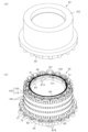
- FIG. 2 is a perspective view showing the appearance of the stator unit
- FIG. 3 is a plan view of the stator unit
- 4, (a) is a cross-sectional view along the line 4a-4a in FIG. 3
- (b) is a cross-sectional view along the line 4b-4b in FIG.
- FIG. 5 is an exploded perspective view of the core assembly
- 6, (a) is a vertical cross-sectional view of the core assembly
- (b) is a cross-sectional view of the core assembly
- FIG. 1 is a vertical cross-sectional view of a rotating electric machine in the first embodiment
- FIG. 2 is a perspective view showing the appearance of the stator unit
- FIG. 3 is a plan view of the stator unit
- 4 is a cross-sectional view along the line 4a-4a in FIG. 3
- (b) is a cross-sectional view along the line 4b-4b
- FIG. 7 is a perspective view of a position regulating member;
- FIG. 8 is a perspective view showing a state in which the position regulating member is attached to the core assembly;
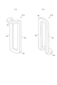
- FIG. 9 is a perspective view showing the configuration of the partial winding,
- FIG. 10 is a perspective view showing the configuration of the position regulating member;
- FIG. 11 is a vertical cross-sectional view of the stator unit,
- FIG. 12 is a perspective view of the wiring module,
- FIG. 13 is an exploded perspective view of the stator unit;
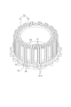
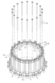
- FIG. 14 is a perspective view for explaining the assembly process of the stator unit;
- FIG. 15 is a perspective view for explaining the assembly process of the stator unit;
- FIG. 16 is a perspective view for explaining the assembly process of the stator unit;
- FIG. 17 is a perspective view for explaining the assembly process of the stator unit;
- FIG. 18 is a longitudinal sectional view of the stator unit,
- FIG. 19 is a perspective view showing the appearance of the stator unit in the second embodiment,
- FIG. 20 is a plan view of the stator unit, 21, (a) is a cross-sectional view taken along line 21a-21a in FIG. 20, and (b) is a cross-sectional view taken along line 21b-21b in FIG.
- FIG. 22 is an exploded perspective view showing the core assembly and the position regulating member;
- FIG. 23 is a longitudinal sectional view of the stator unit,
- FIG. 24 is a perspective view showing the appearance of the stator unit in the third embodiment,
- FIG. 25 is a longitudinal sectional view of the stator unit, FIG.
- FIG. 26 is an exploded perspective view of the stator unit;
- FIG. 27 is an exploded perspective view of the stator unit;
- FIG. 28 is a perspective view showing the appearance of the stator unit in the fourth embodiment;
- FIG. 29 is a perspective view showing a state in which the position regulating member is separated in the stator unit;
- FIG. 30 is a perspective view showing the appearance of the stator unit in the fifth embodiment;
- FIG. 31 is a perspective view showing a state in which the position regulating member is separated in the stator unit;
- FIG. 32 is a diagram showing partial windings of a modified example.
- the rotary electric machine in this embodiment is used as a vehicle power source, for example.
- the rotating electric machine can be widely used for industrial use, vehicle use, aircraft use, home appliance use, OA equipment use, game machine use, and the like.
- parts that are the same or equivalent to each other are denoted by the same reference numerals in the drawings, and the description of the same reference numerals is used.
- the rotary electric machine 10 is an outer rotor type surface magnet type polyphase AC motor, and is used as an in-wheel motor of a vehicle.
- FIG. 1 is a vertical cross-sectional view of a rotating electrical machine 10.
- the direction in which the rotation axis extends is defined as the axial direction
- the direction radially extending from the center of the rotation axis is defined as the radial direction
- the direction extending circumferentially about the rotation axis is defined as the circumferential direction.
- the rotary electric machine 10 is roughly divided into a rotary electric machine main body having a rotor 20 and a stator unit 30 including a stator 40.
- the rotary electric machine main body is fixed to a vehicle body (not shown).
- a substantially cylindrical spindle 11 and a hub 12 fixed to a wheel (not shown) are integrated.
- the hub 12 has an insertion hole 13 through which the spindle 11 is inserted.
- the hub 12 is rotatably supported by a pair of bearings 14 and 15 while the spindle 11 is inserted through the insertion hole 13 of the hub 12 .
- the direction in which the axis serving as the center of rotation extends (horizontal direction in FIG. 1) is the axial direction, and the rotary electric machine 10 is installed in the vehicle so that the axial direction is horizontal or substantially horizontal. It's becoming
- the rotor 20 and the stator 40 are arranged to face each other in the radial direction with an air gap therebetween.
- a stator unit 30 is fixed to the spindle 11 and a rotor 20 is fixed to the hub 12 . Therefore, the hub 12 and rotor 20 are rotatable with respect to the spindle 11 and stator unit 30 .
- the rotor 20 corresponds to the "field element" and the stator 40 corresponds to the "armature".
- the rotor In a state in which the integrated body of the spindle 11 and the stator unit 30 and the integrated body of the hub 12 and the rotor 20 are assembled with each other, the rotor is provided on one axial end side of the rotor 20 (base end side of the spindle 11).
- a cover 16 is fixed.
- the rotor cover 16 has an annular plate shape, and is fixed to the rotor 20 with fasteners such as bolts with the bearing 17 interposed between the rotor cover 16 and the stator unit 30 .
- the rotor 20 has a substantially cylindrical rotor carrier 21 and an annular magnet unit 22 fixed to the rotor carrier 21 .
- the rotor carrier 21 has a tubular portion 23 having a cylindrical shape and an end plate portion 24 provided on one axial end side of the tubular portion 23 .
- a magnet unit 22 is fixed annularly.
- the other axial end of the rotor carrier 21 is open.
- the rotor carrier 21 functions as a magnet holding member.
- a through hole 24a is formed in the central portion of the end plate portion 24, and the hub 12 is fixed to the end plate portion 24 by a fastener such as a bolt while being inserted through the through hole 24a.
- the magnet unit 22 is composed of a plurality of permanent magnets arranged so that their polarities alternate along the circumferential direction of the rotor 20 . Thereby, the magnet unit 22 has a plurality of magnetic poles in the circumferential direction.
- the magnet unit 22 corresponds to the "magnet section".
- the permanent magnet is, for example, a sintered neodymium magnet having an intrinsic coercive force of 400 [kA/m] or more and a residual magnetic flux density Br of 1.0 [T] or more.
- the magnet unit 22 has a plurality of polar anisotropic permanent magnets, and each magnet is magnetized on the d-axis side (portion near the d-axis) and the q-axis side (portion near the q-axis).
- the orientation of the easy axis is different, the orientation of the easy axis of magnetization is parallel to the d-axis on the d-axis side, and the orientation of the easy axis of magnetization is perpendicular to the q-axis on the q-axis side.
- an arcuate magnet magnetic path is formed along the direction of the axis of easy magnetization.
- each magnet is oriented such that the direction of the axis of easy magnetization is parallel to the d-axis on the d-axis side, which is the magnetic pole center, compared to the q-axis side, which is the magnetic pole boundary.
- FIG. 2(a) and 2(b) are perspective views showing the appearance of the stator unit 30, of which FIG. 2(b) shows a state where the resin mold provided in the stator unit 30 is removed.
- . 3 is a plan view of the stator unit 30,
- FIG. 4(a) is a sectional view taken along line 4a-4a in FIG. 3
- FIG. 4(b) is a sectional view taken along line 4b-4b in FIG. be.
- the stator unit 30 generally includes a stator 40, a radially inner stator holder 50, and a wiring module 130.
- the stator 40 has a toothless structure and has a stator winding 41 and a stator core 42 .
- the stator core 42 and the stator holder 50 are integrally provided as a core assembly CA, and a plurality of partial windings 81 constituting the stator winding 41 are assembled to the core assembly CA.
- the stator winding 41 corresponds to the "armature winding”
- the stator core 42 corresponds to the "armature core”
- the stator holder 50 corresponds to the "armature holding member”.
- the core assembly CA corresponds to the "supporting member”.
- a range including the stator 40 and the wiring module 130 of the stator unit 30 is covered with a resin material. Therefore, the stator unit 30 is covered with the resin mold portion 150 except for a part thereof, and its outer peripheral surface is formed to be a resin surface (see FIG. 2(a)).
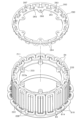
- FIG. 5 is an exploded perspective view of the core assembly CA
- FIG. 6(a) is a longitudinal sectional view of the core assembly CA
- FIG. 6(b) is a lateral sectional view of the core assembly CA (FIG. 6 ( 6b-6b line sectional view of a)).
- the core assembly CA has the stator core 42 and the stator holder 50 assembled radially inward thereof.
- the stator core 42 is integrally attached to the outer peripheral surface of the stator holder 50 .
- the stator core 42 is configured as a core sheet laminate in which core sheets made of magnetic steel sheets, which are magnetic materials, are laminated in the axial direction, and has a cylindrical shape with a predetermined thickness in the radial direction.
- the radially outer peripheral surface of the stator core 42 is curved without irregularities, and the stator windings 41 are assembled to the outer peripheral surface (that is, the rotor 20 side of the radially inner and outer surfaces).
- the stator core 42 functions as a back yoke.
- the stator core 42 is configured by laminating a plurality of core sheets, which are punched into, for example, an annular plate shape, in the axial direction.
- a stator core 42 having a helical core structure may be used. In the stator core 42 of the helical core structure, a band-shaped core sheet is used, and this core sheet is wound in an annular shape and laminated in the axial direction, thereby forming a cylindrical stator core 42 as a whole. It is
- a plurality of protrusions 43 are provided at predetermined intervals in the circumferential direction on the inner peripheral surface on the radially inner side.
- the protrusions 43 are portions that locally increase the radial thickness of the stator core 42 , and the portions thickened by the protrusions 43 are formed with through holes 44 penetrating in the axial direction.
- the stator 40 has a slotless structure that does not have teeth for forming slots. can be anything. These (A) to (C) substantially correspond to the toothless structure.
- an inter-conductor member is provided between each conductor portion (intermediate conductor portion 82 described later) in the circumferential direction, and as the inter-conductor member, the width dimension of the inter-conductor member in the circumferential direction in one magnetic pole is Wt, Bs is the saturation magnetic flux density of the member between the conductors, Wm is the width dimension of the magnet in the circumferential direction of one magnetic pole, and Br is the residual magnetic flux density of the magnet. material is used.
- stator 40 In the stator 40, a member between conductors is provided between each conductor portion (intermediate conductor portion 82) in the circumferential direction, and a non-magnetic material is used as the member between conductors.
- the stator 40 has a configuration in which no member between conductors is provided between conductors (intermediate conductors 82) in the circumferential direction.
- the stator holder 50 includes a cylindrical portion 51 to which the stator core 42 is assembled, a projecting portion 52 projecting radially outward from the cylindrical portion 51 , and a bottom portion 53 formed radially inward of the cylindrical portion 51 . have.
- the bottom portion 53 is provided with a through-hole 54 that penetrates in the axial direction, and the spindle 11 can be inserted through the through-hole 54 .
- the stator holder 50 is made of, for example, metal such as aluminum or cast iron, or carbon fiber reinforced plastic (CFRP).
- the cylindrical portion 51 has an outer peripheral surface formed in two steps, and has a small diameter portion 55 and a large diameter portion 56 .
- a stator core 42 is assembled to the small diameter portion 55 .
- a plurality of concave portions 57 corresponding to the convex portions 43 of the stator core 42 are provided in the small-diameter portion 55 .
- the protrusions 43 on the stator core 42 side enter into the recesses 57 .
- An end surface 58 is formed on the small diameter portion 55 side of the large diameter portion 56 , and a plurality of axially extending hole portions 59 are formed in the end surface 58 so as to be open.
- a female thread is formed at the hole portion 59 .
- a coolant passage 60 for circulating a coolant such as cooling water is formed in the cylindrical portion 51 .
- the refrigerant passage 60 extends in the axial direction and is annularly provided along the cylindrical portion 51, and allows the refrigerant to flow in the circumferential direction between an inlet portion and an outlet portion (not shown).
- the coolant passages 60 are formed by being recessed radially inward for each of the recesses 57 .
- the coolant passage 60 may be formed in an annular shape without recessing each recess 57 .
- the cylindrical portion 51 has a double structure consisting of a radially outer outer cylindrical member and a radially inner inner cylindrical member, and a clearance space between the outer cylindrical member and the inner cylindrical member serves as a coolant passage 60. I hope you are.
- the coolant passage 60 is connected to an external circulation path for circulating the coolant.
- the external circulation path is provided with, for example, an electric pump and a heat dissipation device such as a radiator.
- a plurality of projecting portions 61 are provided on the overhanging portion 52 at predetermined intervals in the circumferential direction.
- a through-hole 62 is formed through each of the projecting portions 61 in the axial direction.
- a female thread is formed in each of the through holes 62 .
- the number of protrusions 43 (the number of through-holes 44) of the stator core 42 and the number of protrusions 61 are the same, for example, 18 in this embodiment.
- FIG. 7 is a perspective view of the position regulating member 70
- FIG. 8 is a perspective view showing a state where the position regulating member 70 is attached to the core assembly CA.
- the position regulating member 70 has an annular portion 71 having a larger diameter than the large diameter portion 56 of the stator holder 50, and the annular portion 71 is provided with a plurality of projecting portions 72 projecting radially outward. It is The protrusions 72 are provided at predetermined intervals in the circumferential direction, and the positions of the protrusions 72 match the positions of the protrusions 61 provided on the protrusion 52 of the stator holder 50 . A through-hole 73 is formed in each protruding portion 72 so as to extend therethrough in the axial direction.
- the annular portion 71 is provided with restricting portions 75 and 76 for restricting the position of transition portions (transition portions 83 and 84 to be described later) of the partial winding 81 assembled to the core assembly CA.
- the restricting portions 75 extend radially inward from the annular portion 71 and are provided at predetermined intervals in the circumferential direction.
- the restricting portions 76 extend axially from the annular portion 71 and are provided at predetermined intervals in the circumferential direction. is provided.
- These restricting portions 75 and 76 are convex portions extending in the circumferential direction, and are provided so as to be alternately arranged in the circumferential direction.
- the position regulating member 70 is a member that plays a role of regulating the position of the partial winding 81, and is preferably a highly rigid member.
- the position regulating member 70 is made of metal, such as aluminum, an aluminum alloy, or cast iron.
- the position regulating member 70 is attached to the protruding portion 52 of the stator holder 50 . That is, by screwing a bolt 77 as a fixture to the protruding portion 61 on the overhanging portion 52 side and the protruding portion 72 on the position regulating member 70 side, the position regulating member 70 is fixed to the core assembly CA. ing. In this state, the large-diameter portion 56 of the stator holder 50 and the position regulating member 70 face each other in the radial direction, and an annular space is formed between them. The position of the partial winding 81 is restricted by this annular space and the restricting portions 75 and 76 of the position restricting member 70 . However, the details will be described later.
- An annular internal space is formed on the inner peripheral side of the cylindrical portion 51, and an electric component that constitutes an inverter as a power converter, for example, may be arranged in the internal space.
- An electrical component is, for example, an electrical module in which semiconductor switching elements and capacitors are packaged.
- stator winding 41 assembled to the core assembly CA.
- the state in which the stator winding 41 is assembled to the core assembly CA is as shown in FIGS.
- a plurality of partial windings 81 forming the winding 41 are assembled in a state of being arranged in the circumferential direction.
- the stator winding 41 has a plurality of phase windings, and is formed in a cylindrical shape (annular shape) by arranging the phase windings of each phase in a predetermined order in the circumferential direction.
- the stator winding 41 is configured to have three phase windings by using U-phase, V-phase and W-phase windings.
- the stator 40 includes, in the axial direction, a portion corresponding to a coil side CS radially facing the stator core 42 and a coil end axially outside the coil side CS. and portions corresponding to CE1 and CE2.
- the coil side CS is also a portion facing the magnet unit 22 of the rotor 20 in the radial direction.
- the partial windings 81 are assembled in a state in which both ends in the axial direction protrude axially outward (that is, toward the coil ends CE1 and CE2) from the stator core 42 .
- the partial windings 81 are provided according to the number of poles of the rotary electric machine 10, and a plurality of partial windings 81 are connected in parallel or in series for each phase.
- the number of magnetic poles is 24, but the number is arbitrary.
- Each of the partial windings 81 is provided so that one of both ends in the axial direction is bent in the radial direction and the other is not bent in the radial direction.
- Half of the partial windings 81 among all the partial windings 81 are bent radially inward at one axial end side.
- the remaining half of the partial windings 81 are bent at the other end in the axial direction, and are bent radially outward at the bent side.
- the partial winding 81 having the bent portion that is bent radially inward is referred to as the "partial winding 81A”
- the partial winding having the bent portion that is bent radially outward. 81 is also called "partial winding 81B".
- each partial winding 81A, 81B will be described in detail.
- 9(a) and 9(b) are perspective views showing the configuration of partial windings 81A and 81B.
- Each of the partial windings 81A and 81B is formed by winding a conductor material in multiple layers, and includes a pair of intermediate conductor portions 82 that are provided in parallel and in a straight line, and a pair of intermediate conductor portions 82 as an axis. It has a pair of transition portions 83 and 84 connected at both ends thereof.
- the pair of intermediate conductor portions 82 and the pair of bridge portions 83 and 84 form an annular shape.
- the pair of intermediate conductor portions 82 are spaced apart by a predetermined coil pitch, and the intermediate conductor portion 82 of the partial winding 81 of the other phase can be arranged between the pair of intermediate conductor portions 82 in the circumferential direction.
- the pair of intermediate conductor portions 82 are separated by two coil pitches, and one intermediate conductor portion 82 of the partial winding 81 of the other two phases is arranged between the pair of intermediate conductor portions 82. It is configured to be When the partial windings 81A and 81B are arranged side by side in the circumferential direction, the intermediate conductor portions 82 of the different partial windings 81A and 81B are arranged side by side in the circumferential direction in close proximity.
- the transition portions 83 and 84 on both sides in the axial direction are provided as portions corresponding to the coil ends CE1 and CE2 (see FIG. 4A).
- the other transition portion 84 is formed without being bent in the radial direction.
- the transition portion 83 is the "flexion side transition portion”
- the transition portion 84 is the "non-flexion side transition portion”.
- the bridging portion 83 is provided so as to be bent in a direction orthogonal to the intermediate conductor portion 82, that is, in a direction orthogonal to the axial direction.
- the partial windings 81A and 81B are substantially L-shaped when viewed from the side.
- the connecting portion 83 is bent radially in a different direction.
- the connecting portion 83 is bent radially inward
- the connecting portion 83 is bent radially outward. It is In this case, assuming that the partial windings 81A and 81B are arranged side by side in the circumferential direction, it is assumed that the crossover portions 83 of the partial windings 81A and 81B have different shapes in plan view (planar shapes in the radial direction). It is preferable that the crossover portion 83 of the partial winding 81A has a narrower circumferential width toward the distal end, and the crossover portion 83 of the partial winding 81B has a wider circumferential width toward the distal end.
- the intermediate conductor portions 82 are provided as coil side conductor portions arranged one by one in the circumferential direction on the coil side CS.
- each of the bridging portions 83 and 84 is provided as a coil end wire portion that connects the in-phase intermediate wire portions 82 at two different positions in the circumferential direction in the coil ends CE1 and CE2.
- the partial windings 81A and 81B are formed by winding the conductor material in multiple layers so that the cross section of the conductor assembly portion is square.
- the wire rods are arranged in a plurality of rows in the circumferential direction and in a plurality of rows in the radial direction, so that the cross section is formed to have a substantially rectangular shape.
- Each of the partial windings 81A and 81B is preferably covered with an insulating material in a state in which the conductor material is wound in multiple layers. Although a detailed description by illustration is omitted, it is preferable that each intermediate conductor portion 82 in the partial windings 81A and 81B is covered with a sheet-like insulating cover. For example, a configuration in which an insulating film material is wrapped around the intermediate conductor portion 82 is conceivable. Moreover, it is preferable that the transition portions 83 and 84 are attached with an insulating cover that is molded in accordance with the shape of the transition portion. The insulating cover can insulate the connecting portions of the partial windings 81A and 81B. Alternatively, the entire partial windings 81A and 81B may be coated with a resin material by resin immersion or the like.
- the position of the partial winding 81 is regulated by the position regulating member 70 on the coil end CE2 side (lower side in FIG. 4A). be.
- the position of the partial winding 81 is regulated by the position regulating member 100 different from the position regulating member 70 on the coil end CE1 side (upper side in FIG. 4A). That is, the position of each partial winding 81 is regulated by the position regulating member 70 on the side (CE2 side) where the transition portion 83 is bent radially outward among both ends in the axial direction, whereas the transition portion 83 is regulated in the radial direction.
- the position of the inwardly bent side (CE1 side) is restricted by the position restriction member 100 .
- FIG. 10(a) is a perspective view of the position regulating member 100
- FIG. 10(b) shows a state in which the first annular member 110 and the second annular member 120 constituting the position regulating member 100 are separated from each other. It is a perspective view showing.
- the position regulating member 100 has a first annular member 110 and a second annular member 120 which are formed in an annular shape and are provided in a state of being superimposed in the axial direction.
- the first annular member 110 is provided in contact with the axial end face of the stator core 42
- the second annular member 120 is axially opposite to the stator core 42 across the first annular member 110 .
- the position of the partial winding 81 is restricted by a position restricting member 100 having a first annular member 110 and a second annular member 120 that can be separated from each other.
- Each of the annular members 110 and 120 is a member that plays a role of regulating the position of the partial winding 81, and is preferably a highly rigid member.
- the annular members 110 and 120 are made of metal, such as aluminum, aluminum alloy, cast iron, or the like.
- the first annular member 110 has an annular portion 111 and restricting portions 112 and 113 provided on the annular portion 111 at predetermined intervals.
- the restricting portion 112 is provided so as to extend axially from the annular portion 111
- the restricting portion 113 is provided so as to extend radially outward from the annular portion 111 .
- These restricting portions 112 and 113 are arranged alternately in the circumferential direction.
- a through hole 114 is formed in each restricting portion 112 so as to extend therethrough in the axial direction.
- a plurality of restricting portions 112 among the restricting portions 112 arranged in the circumferential direction are provided with protruding portions 115 protruding radially inward.
- the second annular member 120 has an annular portion 121 and restricting portions 122 provided on the annular portion 121 at predetermined intervals.
- the restricting portion 122 is provided so as to extend axially from the annular portion 121 and is bent radially outward at its distal end side.
- a through hole 123 is formed through the annular portion 121 in the axial direction.
- the annular portions 111 and 121 of the respective annular members 110 and 120 are overlapped to form the respective annular members.
- the through holes 114 and 123 of the members 110 and 120 are communicated in the axial direction.
- the restricting portion 113 on the first annular member 110 side and the restricting portion 122 on the second annular member 120 side face each other while being spaced apart from each other in the axial direction (vertical direction in the figure).
- At least one of the annular members 110 and 120 is provided with an engaging portion by, for example, uneven engagement in order to suppress mutual positional deviation when the annular members 110 and 120 are superimposed. Good. As a result, the annular members 110 and 120 are prevented from being dislocated during assembly to the core assembly CA.
- the position regulating member 100 (the first annular member 110 and the second annular member 120) is fixed to the core assembly CA by a long bolt 101. Specifically, as shown in FIGS. 4A and 4B, the position regulating member 100 is attached to the axial end surface of the stator core 42 . In the assembled state, the through holes 114 and 123 of the annular members 110 and 120, the through hole 44 on the side of the stator core 42, and the hole portion 59 on the side of the stator holder 50 communicate in the axial direction. A position restricting member 100 is fixed to the core assembly CA by screwing a long bolt 101 into a series of holes.
- FIGS. 11(a) and 11(b) are enlarged views showing a part of FIGS. 4(a) and 4(b).
- FIG. 11(a) corresponds to FIG. b) corresponds to FIG. 4(b).
- the annular portion 71 of the position regulating member 70 and the large diameter portion 56 of the stator holder 50 face each other in the radial direction.
- a transition portion 84 (a transition portion on the non-flexing side) of the partial winding 81A is inserted into the annular space formed therebetween. This restricts the radial and axial positions of the partial winding 81A on the coil end CE2 side. Further, the restricting portion 75 of the position restricting member 70 enters the annular inner side of the transition portion 84 of the partial winding 81A, thereby restricting the circumferential and axial positions of the partial winding 81A on the coil end CE2 side.
- the restricting portion 76 of the position restricting member 70 enters the annular inner side of the transition portion 83 (flexion-side transition portion) of the partial winding 81B, thereby restricting the circumferential position of the partial winding 81B on the coil end CE2 side. It is
- the annular portion 111 of the first annular member 110 restricts the axial position of the partial winding 81A.
- the restricting portion 112 of the first annular member 110 enters the annular inner side of the transition portion 83 of the partial winding 81A, thereby restricting the circumferential and radial positions of the partial winding 81A on the coil end CE1 side. .
- the transition portion 84 of the partial winding 81B is arranged on the side of the coil end CE1. are restricted in their circumferential and axial positions.
- the position regulating members 70 and 100 are provided as common members for regulating the respective positions of the partial windings 81A and 81B.
- the wiring module 130 is a winding connection member that is electrically connected to the partial windings 81A and 81B in the stator winding 41.
- the wiring module 130 connects the partial windings 81 of each phase in parallel. Alternatively, they are connected in series, and the phase winding of each phase is connected to the neutral point.
- the wiring module 130 is provided on the coil end CE1 side, that is, on the side where the connecting portion 83 of the partial winding 81A is bent radially inward among both axial sides. ing.
- the wiring module 130 is formed in an annular shape, and is provided with a plurality of pedestals 131 at predetermined intervals in the circumferential direction.
- the wiring module 130 is fixed to the position regulating member 100 .
- the wiring module 130 is fixed to the position regulating member 100 by fixing the pedestal portion 131 to the projecting portion 115 (see FIG. 10A) provided on the first annular member 110 .
- the transition portions 84 of the partial winding 81B are arranged in a ring, and the wiring module 130 is provided radially inside the transition portions 84 .
- the wiring module 130 has a wiring member such as a busbar for each phase, and the wiring member is connected to the power input/output line of each phase.
- the power input/output lines of each phase are connected to an inverter (not shown) for power input/output.
- the wiring module 130 may be integrally provided with a current sensor that detects the phase current of each phase.
- the wiring module 130 may be formed in an annular shape according to the form of the stator winding 41, and may be a polygonal annular one or a substantially C-shaped one in which a part of the annular portion is missing. It may be of any shape.
- FIG. 13 is an exploded perspective view in which the stator unit 30 is disassembled in order of assembly.
- FIG. 13 shows the stator unit 30 disassembled into the core assembly CA, partial winding 81A, position regulating members 70 and 100, partial winding 81B, and wiring module .
- 14 to 17 are perspective views showing the structure of the stator unit 30 during the assembly process.
- each partial winding 81A is arranged with the through hole 44 of the stator core 42 as the center position in the circumferential direction.
- the transition portion 84 of the partial winding 81A (the transition portion on the non-flexing side) faces the axial end face of the overhanging portion 52 of the stator holder 50, and They are arranged in the circumferential direction along the large diameter portion 56 .
- the position regulating member 70 on the coil end CE2 side is assembled to the assembly in the state of FIG. At this time, the position regulating member 70 is assembled from above in the axial direction, and the position regulating member 70 is fixed to the core assembly CA by screwing the bolt 77 .
- the transition portion 84 of each partial winding 81A enters between the annular portion 71 of the position regulating member 70 and the large diameter portion 56 of the stator holder 50, and the partial winding is performed on the coil end CE2 side.
- the radial position of the wire 81A is restricted.
- the restricting portion 75 of the position restricting member 70 enters between the pair of intermediate conductor portions 82 of each partial winding 81A and axially opposes the distal end portion of the transition portion 84, so that the partial winding is performed on the coil end CE2 side.
- the circumferential and axial positions of the wire 81A are restricted.
- the position regulating member 100 on the coil end CE1 side is assembled to the assembly in the state of FIG.
- Annular members 110 and 120 of position regulating member 100 are assembled from the axially outer side of transition portion 83 of partial winding 81A and fixed to core assembly CA by screwing long bolt 101 .
- the annular portion 111 of the first annular member 110 restricts the axial position of the partial winding 81A.
- the restricting portion 112 of the first annular member 110 enters the annular inner side of the transition portion 83 of the partial winding 81A, thereby restricting the circumferential and radial positions of the partial winding 81A on the coil end CE1 side.
- a plurality of partial windings 81B are attached to the assembly in the state of FIG.
- the partial winding 81B is assembled from the radially outer side so that each intermediate conductor portion 82 is inserted between the intermediate conductor portions 82 on the partial winding 81A side.
- the restricting portion 76 of the position restricting member 70 enters the annular inner side of the transition portion 83 of the partial winding 81B, thereby restricting the circumferential position of the partial winding 81B on the coil end CE2 side.
- the transition portion 84 of the partial winding 81B is arranged between the restricting portion 113 of the first annular member 110 and the restricting portion 122 of the second annular member 120, the partial winding 81B is arranged on the side of the coil end CE1. are regulated in circumferential and axial positions.
- the wiring module 130 is attached to the assembly in the state of FIG. 17 (see FIG. 4(b)).
- a sheet-like (band-like) coil cover 140 is provided radially outwardly of the partial windings 81A and 81B as a restraining member for binding the partial windings 81A and 81B. installed.
- the coil cover 140 is an endless cover formed in an annular shape, and is provided so as to cover the partial windings 81A and 81B from the outside in the radial direction.
- the coil cover 140 is provided in a range including at least the coil side CS in the axial direction, and is divided into a plurality of parts in the axial direction as shown.
- the coil cover 140 may be provided as a single cover.
- the coil cover 140 is preferably made of a sheet material that has insulating properties and is flexurally deformable.
- the sheet material is, for example, an insulating resin sheet.
- the coil cover 140 may be spring-shaped and have binding force.
- the coil cover 140 may be configured using an insulating material such as synthetic resin, or may be configured such that the conductive material is covered with an insulating material such as synthetic resin. That is, it is preferable that the coil cover 140 has insulation at least on its outer surface.
- a string-like member may be wound radially outwardly of each of the partial windings 81A and 81B.
- a range including the stator windings 41 and the wiring module 130 is resin-molded.
- a resin molded portion 150 is formed by integrally resin-molding a range including the coil ends CE1, CE2 and the coil side CS on both sides in the axial direction.
- An insulating layer is formed between the wires 81A, 81B and the position regulating members 70, 100.
- FIG. 18A and 18B are cross-sectional views showing the stator unit 30 with the resin mold portion 150 added.
- 18(a) is a diagram corresponding to FIG. 4(a)
- FIG. 18(b) is a diagram corresponding to FIG. 4(b).
- the resin molded portion 150 extends in the axial direction from the position regulating member 70 on the one axial end side to the position regulating member 100 on the other axial end side, and It is provided to include each intermediate conductor portion 82 of the partial windings 81A and 81B.
- the transition portions 83, 84 of the partial windings 81A, 81B and the position regulating member 70 are arranged with a slight separation from each other, and the separated portions are filled with a resin material. An insulating layer is thus formed.
- the transition portions 83 and 84 of the partial windings 81A and 81B and the position regulating member 100 are arranged with a slight separation from each other, and the separated portions are filled with a resin material.
- An insulating layer is formed by
- an insulating layer is formed by filling a resin material between the intermediate conductor portions 82 arranged in the circumferential direction.
- each transition portion 83, 84 and position regulating members 70, 100 are separated from each other.
- a gap portion due to the separation is filled with a resin material.
- a resin material (insulating material) is interposed between the stator core 42 and the stator holder 50 .
- the stator core 42 and the stator holder 50 are formed with unevenness in the radially inner and outer facing portions (see FIG. 5), and the stator core 42 and the stator holder 50 are fitted together by fitting the unevenness. Combined.
- a resin material is interposed in the gap between these two members.
- the stator core 42 may be attached to the stator holder 50 by shrink fitting, pin fixing, or the like, in addition to the concave-convex fitting described above.
- the insulation layers of the coil ends CE1 and CE2 and the insulation layers of the coil sides CS that is, the insulation layers on the outer side in the axial direction of the stator core 42 and the insulation layers on the inner and outer sides in the radial direction of the stator core 42 are made of the same resin material. It should be
- the gap between the stator core 42 and the stator holder 50 can be used as a passage through which the resin material (insulating material) flows.
- passages resin passages
- the end surface 58 of the stator holder 50 is provided with a plurality of protrusions in the circumferential direction to form a gap between the end surface 58 of the stator holder 50 and the axial end surface of the stator core 42, and the gap
- the resin material to flow through.
- At least one of the stator core 42 and the stator holder 50 is provided with a through-hole penetrating between both end surfaces in the axial direction. The configuration may be such that it is used as a resin passage that makes it possible.
- the insulating layers of the coil ends CE1, CE2 and the insulating layer of the coil side CS may be made of different resin materials.
- the insulating material interposed between the intermediate conductor portions 82 of the partial windings 81A, 81B and the stator core 42 is preferably a resin material having a higher adhesive strength than the insulating layers of the coil ends CE1, CE2. This resin material is preferably cured at the same time during the preheating process during molding.
- the insulating material interposed between the intermediate conductor portion 82 of the partial windings 81A, 81B and the stator core 42 is a resin material having a higher thermal conductivity than the insulating layers of the coil ends CE1, CE2. good.
- the insulating layer between the intermediate conductor portion 82 and the stator core 42 is preferably made of resin having a thermal conductivity of 0.3 W/mK or more, for example.
- a temperature detection section 160 for detecting the temperature of the stator 40 may be provided inside the resin mold section 150 .
- the temperature detecting section 160 is provided integrally with the position regulating member 100 or the wiring module 130, for example, and these are collectively resin-molded.
- the resin mold part 150 should be provided at least on each of the coil ends CE1 and CE2. In other words, a configuration in which the resin molded portion 150 is not provided on the coil side CS may be employed.
- the partial windings 81A There is a concern that the insulation of the stator winding 41 may be impaired due to the contact between 81B and the position regulating members 70 and 100 .
- the resin molded portion 150 is provided and an insulating layer is interposed between the partial windings 81A, 81B and the position regulating members 70, 100, thereby suppressing deterioration in insulating properties. As a result, the insulation state of the stator winding 41 can be properly maintained.
- position regulation is performed in two different directions in each of the partial windings 81A and 81B. It becomes possible. Since the insulating layer is interposed between the transition portions 83, 84 and the position regulating members 70, 100, it is possible to suppress the deterioration of the insulation properties of the partial windings 81A, 81B due to the position regulating members 70, 100.
- each of the partial windings 81A and 81B is formed in an annular shape by multiple windings of a conductive wire on the basis of the inner circumference side.
- the separation distance (insulation distance) between the transition portions 83 and 84 and the position regulating members 70 and 100 is designed.
- tolerance design of the partial windings 81A and 81B is facilitated.
- the partial windings 81A and 81B are caused to interfere with each other. Instead, they can be arranged so as to overlap each other in the circumferential direction. In this case, since the positions of the partial windings 81A and 81B are restricted using the common position restriction members 70 and 100, the number of parts can be reduced and the configuration can be simplified.
- the transition portions of the partial windings 81A and 81B 83 and 84 are arranged close to each other.
- the position regulating members 70 and 100 are provided so as to enter the annular inner side of the connecting portion of the partial winding 81A and the annular inner side of the connecting portion of the partial winding 81B. made it This makes it possible to easily achieve positional regulation in a plurality of directions in each of the partial windings 81A and 81B.
- the position regulating member 100 is set in a state of being inserted into the annular inner side of the transition portion 83 of the partial winding 81A at the coil end CE1, and is set to a state of facing the transition portion 84 of the partial winding 81B from the outside in the axial direction. It was configured. In this case, in the coil end CE1, the position regulating member 100 can be assembled while considering the bending states of the transition portions 83 and 84 of the partial windings 81A and 81B.
- the position regulating member 100 is configured to have portions (regulating portions 113 and 122) that sandwich the circumferentially extending portion of the transition portion 84 of the partial winding 81B from the annular outer side and the annular inner side, respectively. In this case, since the transition portion 84 of the partial winding 81B is sandwiched from both sides in the axial direction by the position regulating members 100, the position in the axial direction can be properly regulated.
- an annular position regulating member 100 is provided so as to face the transition portions 83 and 84 arranged in the circumferential direction,
- the annular wiring module 130 is fixed to the position regulating member 100 (specifically, the second annular member 120).
- each member is integrally resin-molded within a range including the transition portions 83, 84 of each partial winding 81A, 81B and the position regulating members 70, 100.
- the resin molded portion 150 is formed using the same resin material in each of the coil ends CE1 and CE2.
- an insulating layer is appropriately formed in the portions facing the position regulating members 70 and 100 (the gaps between the transition portions and the position regulating members) around the transition portions 83 and 84 of the partial windings 81A and 81B. can do.
- the structural members including the respective position regulating members 70 and 100 on both ends in the axial direction and the intermediate conductor portions 82 of the partial windings 81A and 81B are resin-molded. Thereby, the resin molded portion 150 is formed in a range including the entire partial windings 81A and 81B, and unintended insulation deterioration in the partial windings 81A and 81B can be appropriately suppressed.
- the gap between the intermediate conductor portions 82 of the partial windings 81A, 81B and the stator core 42 is a resin material having a higher adhesive strength than the insulating layers of the coil ends CE1 and CE2.
- the intermediate conductor portions 82 of the partial windings 81A and 81B and the stator core 42 and the stator holder 50 is a resin material having a higher thermal conductivity than the insulating layers of the coil ends CE1 and CE2. As a result, it is possible to improve the cooling performance of the intermediate conductor portion 82 .
- the temperature detection part 160 is integrally resin-molded together with the transition parts 83, 84 of the partial windings 81A, 81B and the position regulating member 100. As a result, the resin molded portion 150 can both transfer heat to the temperature detecting portion 160 and fix the temperature detecting portion 160 .
- stator unit 30 By interposing an insulating material forming an insulating layer between the stator core 42 and the stator holder 50, rattling of the stator core 42 with respect to the stator holder 50 can be suppressed. Further, in this case, when the stator unit 30 is manufactured, the gap between the stator core 42 and the stator holder 50 is used as a passage for the insulating material (resin material) to flow. , CE2 can be easily formed (resin molding).
- Passages are formed between the stator core 42 and the stator holder 50 so as to extend in the axial direction at predetermined intervals in the circumferential direction and to allow the flow of the insulating material when the stator unit 30 is manufactured. I hope it is.
- the fixture (long bolt 101) is inserted through each through hole of the stator core 42 and the position regulating member 100, and the fixture is inserted. , are fastened on the opposite side of the position regulating member 100 with the stator core 42 interposed therebetween. This allows the stator core 42 and the position regulating member 100 to be fixed simultaneously.
- FIG. 19(a) and (b) are perspective views showing the appearance of the stator unit 30, of which FIG. 19(b) shows a state where the resin mold provided in the stator unit 30 is removed.
- . 20 is a plan view of the stator unit 30,
- FIG. 21(a) is a cross-sectional view along the line 21a-21a of FIG. 20,
- FIG. 21(b) is a cross-sectional view along the line 21b-21b of FIG. be.
- FIG. 22 is an exploded perspective view showing the core assembly CA and the position regulating member 170 attached to the coil end CE2 side of the core assembly CA in this embodiment.
- the configuration of the coil end CE2 side of the configuration for restricting the winding position in the coil ends CE1 and CE2 is changed. ing.
- a hole portion 59 provided in the large-diameter portion 56 is a through hole penetrating in the axial direction.
- other configurations of the core assembly CA are the same as those shown in FIG. 5 and the like. Also, since there is no change in the configuration of the position regulating member 100 on the coil end CE1 side, description thereof will be omitted.
- the position regulating member 170 is formed in an annular shape, and has an end plate located axially outside the axial end face (lower end face in the drawing) of the large diameter portion 56 of the stator holder 50 . and an annular wall portion 172 extending axially from the outer edge of the end plate portion 171 .
- the end plate portion 171 is provided with a plurality of boss portions 173 at predetermined intervals in the circumferential direction, and each of the boss portions 173 is formed with a through hole 174 penetrating therethrough in the axial direction.
- the annular wall portion 172 is formed to have a larger diameter than the large diameter portion 56 .
- a plurality of restricting portions 175 are provided on the annular wall portion 172 so as to extend in the axial direction.
- the restricting portions 175 are convex portions extending in the circumferential direction, and are provided at predetermined intervals in the circumferential direction.
- the position regulating member 170 is made of, for example, aluminum, an aluminum alloy, cast iron, or the like.
- the position regulating member 170 has a boss portion 173 that is the axial end face of the large diameter portion 56 of the stator holder 50 (lower end face in the drawing). is attached to the stator holder 50 in a state of abutting on the . In this state, the annular wall portion 172 of the position regulating member 170 and the large diameter portion 56 of the stator holder 50 face each other in the radial direction. 84 (transition portion on the non-flexing side) is inserted. This restricts the radial and axial positions of the partial winding 81A on the coil end CE2 side.
- the restricting portion 175 of the position restricting member 170 enters the ring-shaped inner side of the transition portion 83 (flexion-side transition portion) of the partial winding 81B, thereby restricting the circumferential position of the partial winding 81B on the coil end CE2 side.
- the annular wall portion 172 may be provided with a plurality of restricting portions extending radially inward at predetermined intervals in the circumferential direction.
- the restricting portion enters the annular inner side of the transition portion 84 of the partial winding 81A, thereby restricting the circumferential and axial positions of the partial winding 81A on the coil end CE2 side.
- FIGS. 23(a) and 23(b) are cross-sectional views showing the stator unit 30 with the resin mold portion 150 added.
- 23(a) is a diagram corresponding to FIG. 21(a)
- FIG. 23(b) is a diagram corresponding to FIG. 21(b).
- the resin molded portion 150 extends in the axial direction from the position regulating member 170 on the one axial end side to the position regulating member 100 on the other axial end side, and It is provided to include each intermediate conductor portion 82 of the partial windings 81A and 81B.
- the configuration is substantially the same as that of FIGS. 18(a) and 18(b). That is, in each of the coil ends CE1 and CE2, the resin material enters between the transition portions 83 and 84 of the partial windings 81A and 81B and the position regulating members 70 and 100 to form an insulating layer. .
- a resin material (insulating material) is interposed between the stator core 42 and the stator holder 50 .
- the portion of the position regulating member 170 that is opposite to the stator holder 50 across the transition portion 84 of the partial winding 81A and that surrounds the transition portion 84 from the outside in the radial direction is It is a non-molded portion that is not resin-molded (X portion in FIG. 23).
- a part of the position regulating member 170 is exposed to the outside without being resin-molded, thereby improving heat dissipation. That is, in the rotary electric machine 10 , for example, lubricating oil may be dripped inside the rotor carrier 21 to lubricate the stator 40 .
- the non-molded portion (exposed portion) of the position regulating member 170 serves as a heat radiating portion by oil cooling.
- an end plate portion 171 of the position regulating member 170 which is located axially outside the axial end surface of the stator holder 50 , is provided with a hole portion 176 penetrating therethrough in the axial direction.
- the hole portion 176 is preferably provided at a position that does not interfere with the boss portion 173 . In this case, it is possible to fill the annular groove surrounding the large-diameter portion 56 of the stator holder 50 with the resin material through the hole 176 . Therefore, an insulating layer can be properly formed around the position regulating member 170 .
- FIG. 24(a) and (b) are perspective views showing the appearance of the stator unit 200, of which FIG. 24(a) shows the stator unit 200 in a resin-molded state and FIG. ) shows the stator unit 200 without resin molding.
- FIG. 25(a) is a vertical cross-sectional view of the stator unit 200 in a resin-molded state
- FIG. 25(b) is a vertical cross-sectional view of the stator unit 200 in a non-resin-molded state.
- FIG. 26 is an exploded perspective view showing the main components of the stator unit 200.
- the stator unit 200 has a stator 210, a radially inner stator holder 220, and a wiring module 230 as an overview.
- the stator 210 has a toothless structure and has a stator winding 211 and a stator core 212 .
- the stator core 212 and the stator holder 220 are integrally provided as a core assembly CA (see FIG. 26), and the stator windings 211 are assembled to the core assembly CA.
- the stator 210 has substantially the same configuration as the stator 40 described above, and the stator winding 211 is composed of a plurality of partial windings 81A and 81B as described above.
- the stator core 212 has the same configuration as the stator core 42 except that it does not have a plurality of projections on its inner peripheral side.
- the detailed description of the configuration similar to that of the stator 40 is omitted.
- the side (upper side in the drawing) where the transition portion 83 of the partial winding 81A is bent radially inward is the coil end CE1
- the side where 83 is bent radially outward is the coil end CE2.
- the wiring module 230 also has the same configuration as the wiring module 130, so description thereof will be omitted.
- the stator holder 220 has a cylindrical portion 221 to which the stator core 212 is assembled.
- a flange portion 222 extending radially inward is formed at the axial end portion of the cylindrical portion 221 on the side of the coil end CE1. It is
- Each boss portion 223 is provided with a hole portion 223a extending in the axial direction.
- a female screw is formed in each of the holes 223a.
- a protruding portion 225 that protrudes radially outward from the cylindrical portion 221 is provided at the axial end portion on the coil end CE2 side.
- the projecting portion 225 includes an end plate portion 226 extending radially outward from the cylindrical portion 221 (large diameter portion 221a) of the stator holder 220, and an annular annular wall extending axially from the outer edge portion of the end plate portion 226. 227.
- the annular wall portion 227 is formed to have a larger diameter than the large diameter portion 221a.
- a plurality of restricting portions 228 are provided on the annular wall portion 227 so as to extend in the axial direction.
- the restricting portions 228 are convex portions extending in the circumferential direction, and are provided at predetermined intervals in the circumferential direction.
- the projecting portion 225 of the stator holder 220 functions as a position regulating member that regulates the positions of the partial windings 81A and 81B assembled to the core assembly CA on the coil end CE2 side.
- the stator holder 220 is made of, for example, metal such as aluminum or cast iron, or carbon fiber reinforced plastic (CFRP). Although not shown, the stator holder 220, like the stator holder 50, preferably has a coolant passage through which a coolant such as cooling water flows.
- CFRP carbon fiber reinforced plastic
- a position regulating member 240 that regulates the position of the partial winding 81 is attached to the boss portion 223 of the stator holder 220 .
- the position regulating member 240 has an annular portion 241 and a plurality of regulating portions 242 provided on the annular portion 241 at predetermined intervals.
- the restricting portion 242 is provided so as to extend axially from the annular portion 241 .
- the annular portion 241 is formed with a plurality of through holes 243 extending axially as bolt insertion holes.
- the position regulating member 240 is fixed to the stator holder 220 with bolts 245 .
- the position regulating member 240 is made of, for example, aluminum, aluminum alloy, cast iron, or the like.
- a regulating portion 242 that enters the annular inner side of the transition portion 83 of the partial winding 81A is provided on either the radially inner or outer side of the annular portion 241, and , through-holes 243 (fixed portions) that are fixed to the stator holder 220 by bolts 245 are provided.
- the regulating portion 242 and the through hole 243 (fixed portion) are provided at radially inner and outer positions of the position regulating member 240, the positional regulation of the connecting portions 83 arranged in the circumferential direction is hindered. It is possible to fix the position regulating member 240 to the stator holder 220 without doing so.
- the regulating portion 242 becomes smaller due to the restriction of the fixed portion.
- the restricting portion 242 can be provided with sufficient strength.
- each partial winding 81A, 81B will be described in detail with reference to FIGS. 25 to 27.
- FIG. On the coil end CE2 side (lower side in the drawing), the large diameter portion 221a of the stator holder 220 and the annular wall portion 227 of the projecting portion 225 face each other in the radial direction. , the transition portion 84 (the transition portion on the non-bending side) of the partial winding 81A is inserted. This restricts the radial and axial positions of the partial winding 81A on the coil end CE2 side.
- the restricting portion 228 of the projecting portion 225 enters the annular inner side of the transition portion 83 (transition portion on the bending side) of the partial winding 81B, thereby restricting the circumferential position of the partial winding 81B on the coil end CE2 side.
- the axial position of the partial winding 81A is regulated by the annular portion 241 of the position regulating member 240.
- the restricting portion 242 of the position restricting member 240 enters the annular inner side of the transition portion 83 of the partial winding 81A, thereby restricting the circumferential and radial positions of the partial winding 81A on the coil end CE1 side.
- a position regulating member 240 (first position regulating member), which is a separate member from the stator holder 220, is fixed by a bolt 245, while on the side of the coil end CE1, the position regulating member 240 protrudes in the radial direction.
- the overhanging portion 225 (second position regulating member) is integrally formed with the stator holder 220 in a state where the stator holder 220 is closed. According to this configuration, when the partial windings 81A and 81B are assembled to the stator holder 220, the partial windings are first positioned while being restricted by the projecting portion 225 integrally formed on the stator holder 220.
- the position restricting member 240 can be retrofitted to the assembly including the stator holder 220 and the partial windings 81A, 81B.
- the number of parts can be reduced and the assembly work can be simplified, while at the same time, the proper position control member for each of the partial windings 81A and 81B can be obtained. positional regulation can be applied.
- a resin molded portion 250 is formed in a range including the stator windings 211 and the wiring module 230 .
- the configuration of the resin mold portion 250 will be described with reference to FIG. 25(a).
- the resin molded portion 250 extends in the axial direction from the projecting portion 225, which is the position regulating member on one axial end side, to the position regulating member 240 on the other axial end side, and is located between the partial windings 81A and 81B. It is provided to include a conductor portion 82 . In this case, in each of the coil ends CE1 and CE2, the resin material enters between the transition portions 83 and 84 of the partial windings 81A and 81B and the projecting portion 225 and the position regulating member 240, forming an insulating layer. It is configured.
- the portion of the protruding portion 225 that is opposite to the stator holder 220 across the transition portion 84 of the partial winding 81A and surrounds the transition portion 84 from the outside in the radial direction is It is a non-molded portion that is not resin-molded (X portion in FIG. 25(a)). In this case, a part of the overhanging portion 225 is not resin-molded and is exposed to the outside, thereby improving heat dissipation.
- the partial winding 81A has the connecting portion 83 bent radially inward, and the partial winding 81B has the connecting portion 83 bent radially outward.
- the wire length of the partial winding 81A is shorter, and the resistance of the wire is lower, so that the amount of heat generated is likely to be larger.
- the transition portion 83 of the partial winding 81A is accommodated in the annular groove portion formed by the protruding portion 225, thereby enhancing heat dissipation.
- the heat is preferably dissipated to the cooling passages provided in the stator holder 220 .
- FIG. 28 is a perspective view showing the configuration of the stator unit 200 of this embodiment
- FIG. 29 is a perspective view showing a state in which the position regulating member 260 is separated from the stator unit 200 of this embodiment.
- the stator unit 200 is configured to include a position restricting member 260 as a position restricting portion on the coil end CE1 side.
- the stator unit 200 shown in FIG. 28 is different from the stator unit 200 shown in FIG.
- the configuration other than the member 260 is generally the same.
- the configurations of the core assembly CA and the stator winding 211 are the same as in FIG.
- the position regulating member 260 has a first annular portion 261, a second annular portion 262, and a plurality of connecting portions 263 that axially connect the annular portions 261 and 262. are doing.
- the first annular portion 261 is provided with a plurality of axially extending restricting portions 264 at predetermined intervals and a plurality of axially penetrating holes 265 and 266 .
- the hole portions 265 are provided at the same pitch as the restricting portions 264 in the circumferential direction, and the hole portions 265 and the restricting portions 264 are alternately arranged in the circumferential direction.
- the hole portion 266 is provided as a bolt insertion hole through which the bolt 245 is inserted.
- a plurality of axially extending restricting portions 267 are provided at predetermined intervals on the second annular portion 262 .
- a position restricting member 260 is attached to the stator holder 220 on the side of the coil end CE1 (upper side in the drawing).
- the first annular portion 261 of the position restricting member 260 regulates the axial position of the partial winding 81A
- the second annular portion 262 regulates the axial position of the partial winding 81B. position
- the restricting portion 264 of the position restricting member 260 enters the ring-shaped inner side of the transition portion 83 (flexion-side transition portion) of the partial winding 81A, so that the partial winding 81A is rotated in the circumferential and radial directions on the coil end CE1 side. position is restricted.
- the restricting portion 267 of the position restricting member 260 enters between the transition portions 84 (transition portions on the non-flexing side) of the respective winding portions 81B arranged in the circumferential direction, so that the winding portions 81B are aligned on the side of the coil end CE1.
- the position in the circumferential direction is regulated.
- the position regulating member 260 is inserted into the circular inner side of the connecting portion 83 of the partial winding 81A, while facing the circular outer side of the connecting portion 84 of the partial winding 81B. It was configured to be in the state. In this case, the position regulating member 260 can be assembled while considering the bent state of the transition portions 83 and 84 of the partial windings 81A and 81B. In addition, after the partial windings 81A and 81B are assembled, the position regulating member 260 can be axially assembled, thereby facilitating the manufacturing work.
- the first annular portion 261 of the position regulating member 260 is provided with the hole portion 265 penetrating in the axial direction, the first annular portion The flow of the resin material from the outside in the axial direction of 261 to the inside in the axial direction is encouraged. As a result, resin molding is performed in a range including the inside of the hole portion 265 and both sides of the first annular portion 261 in the axial direction. In this case, the resin material reliably flows between the transition portions 83 and 84 of the partial windings 81A and 81B and the position regulating member 260, thereby forming an appropriate resin mold portion 250 (forming an insulating layer). can be realized.
- FIG. 30 is a perspective view showing the configuration of the stator unit 200 of this embodiment
- FIG. 31 is a perspective view showing a state in which the position regulating members 270 and 280 are separated from each other in the stator unit 200 of this embodiment. be.
- the stator unit 200 is configured to include a position restricting member 270 as a position restricting portion on the coil end CE1 side and a position restricting member 280 as a position restricting portion on the coil end CE2 side.
- the configuration of the stator winding 211 is the same as the configuration described above.
- the position restricting member 270 includes an annular portion 271, a plurality of restricting portions 272 extending radially inward from the annular portion 271, and a plurality of restricting portions extending axially from the annular portion 271. 273.
- the restricting portion 273 extends axially from the annular portion 271 and has a shape that is bent at its distal end side and extends radially outward. Further, the annular portion 271 is provided with a projecting portion 274 extending in the axial direction as a portion to be attached to a stator holder (not shown).
- the position regulating member 280 has an annular portion 281, a plurality of regulating portions 282 extending axially from the annular portion 281, and a plurality of regulating portions 283 extending radially outward from the annular portion 281. ing. Further, the annular portion 281 is provided with a projecting portion 284 extending radially inward as a portion to be attached to a stator holder (not shown).
- a position restricting member 270 is attached to the stator holder 220 on the side of the coil end CE2 (lower side in the drawing).
- the restricting portion 272 of the position restricting member 270 enters the ring-shaped inner side of the transition portion 84 of the partial winding 81A (the transition portion on the non-flexing side) of the winding portion 81A, thereby causing the axial movement of the partial winding 81A on the side of the coil end CE2.
- Direction and circumferential position are restricted.
- the regulating portion 273 of the position regulating member 270 enters the annular inner side (bending-side transition portion) of the transition portion 83 of the partial winding 81B, the axial direction and the circumferential direction of the partial winding 81B on the coil end CE2 side. position is restricted.
- a position regulating member 280 is attached to the stator holder 220 on the side of the coil end CE1 (upper side in the drawing).
- the restricting portion 282 of the position restricting member 280 enters the ring-shaped inner side of the transition portion 83 (flexion-side transition portion) of the partial winding 81A, thereby causing the partial winding 81A to move in the circumferential direction on the coil end CE1 side. and radial positions are restricted.
- the restricting portion 283 of the position restricting member 280 enters the annular inner side of the transition portion 84 of the partial winding 81B (transition portion on the non-flexing side), the partial winding 81B is moved in the axial direction and the circumferential direction on the coil end CE1 side. position is regulated.
- the configuration is such that the resin molded portion is formed at each of the coil ends CE1 and CE2 on both sides in the axial direction. good.
- the position regulating members for regulating the positions of the partial windings 81A and 81B are provided at the coil ends CE1 and CE2 on both sides in the axial direction. It is good also as a structure which provides a member. In this case, it is preferable that the coil cover 140 constrains the partial windings 81A and 81B while restricting the positions of the partial windings 81A and 81B only on one side in the axial direction.
- the stator units 30, 200 are configured to include the stator cores 42, 212, but this may be changed to a configuration that does not include the stator cores 42, 212.
- each partial winding 81A, 81B is assembled to the stator holder 50,220.
- an insulating layer resin material
- one partial winding 81A of the two types of partial windings 81A and 81B has a substantially C-shape when viewed from the side, and the other partial winding 81B has a substantially I-shape when viewed from the side. shape.
- the partial winding 81A and 81B the partial winding 81A is pre-attached to the core assembly CA, and the partial winding 81B is post-attached to the core assembly CA.
- a position regulating member is attached to the transition portion of each partial winding 81A, 81B, and the transition portion and the position regulating member are collectively resin-molded.
- the axial end faces of the stator cores 42, 212 and the axial end faces of the stator holders 50, 220 are flush with each other on the coil end CE1 side. good.
- the axial end faces of the stator holders 50 and 220 may project axially beyond the axial end faces of the stator cores 42 and 212 . In this case, an effect of improving heat dissipation can be expected.
- the stator winding 41 in the rotating electrical machine 10 may be configured to have two phase windings (a U-phase winding and a V-phase winding).
- a pair of intermediate conductor portions 82 are provided separated by one coil pitch. may be arranged as long as one is arranged.
- a surface magnet type rotor is used as the rotor 20, but instead of this, an embedded magnet type rotor may be used.
- the rotating electrical machine 10 has an outer rotor structure, but this may be changed to a rotating electrical machine with an inner rotor structure.
- a stator is provided radially outward and a rotor is provided radially inward.
- a rotating armature type rotating electric machine having a field element as a rotor and an armature as a stator is replaced with a rotating field type rotating electric machine having an armature as a rotor and a field element as a stator. It is also possible to employ a rotating electric machine.
- the application of the rotating electrical machine 10 may be other than a driving motor for a vehicle, and may be a rotating electrical machine widely used in moving bodies including aircraft, or a rotating electrical machine used in industrial or household electrical equipment. .
- the disclosure in this specification is not limited to the illustrated embodiments.
- the disclosure encompasses the illustrated embodiments and variations thereon by those skilled in the art.
- the disclosure is not limited to the combinations of parts and/or elements shown in the embodiments.
- the disclosure can be implemented in various combinations.
- the disclosure can have additional parts that can be added to the embodiments.
- the disclosure encompasses omitting parts and/or elements of the embodiments.
- the disclosure encompasses permutations or combinations of parts and/or elements between one embodiment and another.
- the disclosed technical scope is not limited to the description of the embodiments.
- the disclosed technical scope is indicated by the description of the claims, and should be understood to include all modifications within the meaning and range of equivalents to the description of the claims.
- the partial winding includes a pair of intermediate conductor portions (82) provided at a predetermined interval in the circumferential direction, and transition portions provided at one end side and the other end side in the axial direction and connecting the pair of intermediate conductor portions in an annular fashion.
- Position regulating members (70, 100, 170, 225, 240, 260, 260, 70, 100, 170, 225, 240, 260, 70, 100, 170, 225, 240, 260, 70, 100, 170, 225, 240, 260, 70, 70, 70, 70, 70, 70, 70, 70, 70, 70, 70, 70, 70, 70, 70, 70, and 270, 280) regulate the positions of the partial windings assembled to the armature holding member, A rotating electric machine, wherein an insulating layer (150, 250) is interposed between the partial winding and the position regulating member.
- the armature winding has, as the partial windings, a first partial winding and a second partial winding in which the shape of the transition portion at the coil end is different, At least one of the first partial winding and the second partial winding is arranged to overlap each other in the circumferential direction with at least one of the winding ends bent in the radial direction,
- the position regulating member as the common member is inserted into a portion of the first partial winding that is annularly inside the transition portion and a portion of the second partial winding that is annularly inside of the transition portion.
- the position regulating member is a member provided separately from the armature holding member and fixed to the armature holding member by a fixture (101, 245); In the coil end, the connecting portion of the first partial winding is bent in the radial direction, and the connecting portion of the second partial winding is not bent in the radial direction, The position regulating member, which is the common member, enters the annular inner side of the transition portion of the first partial winding, while being the annular outer side of the transition portion of the second partial winding.
- the position regulating member is A member provided separately from the armature holding member and fixed to the armature holding member by a fixture (245), having an annular portion (241, 261), A restricting portion (242, 264) is provided on either one of the radial inner and outer sides of the annular portion, and the restriction portion (242, 264) that enters the annular inner side of the transition portion of the partial winding is provided on the other side.
- each of the transition portions of the plurality of partial windings is arranged in a circumferential direction, and the ring-shaped position regulating member is provided so as to face each of the transition portions arranged in the circumferential direction; 9.
- a wiring module (130) electrically connected to each of the partial windings has an annular shape and is fixed to the position regulating member.
- the insulating layer is formed by integrally resin-molding these members in a range including the transition portion of the partial winding and the position regulating member in at least one of the coil ends on both sides in the axial direction.
- the rotating electrical machine according to any one of Configurations 1 to 9.
- a through hole (265) passing through the annular portion (261) in the axial direction is provided in the position regulating member, and resin molding is performed within a range including the inside of the through hole and both sides of the annular portion in the axial direction.
- the armature has an armature core (42) provided radially inside or radially outside the armature winding, An insulating material is interposed between the intermediate conductor portion of the partial winding and the armature core, and the insulating material is a resin material having higher adhesion than the insulating layer in the coil end. 14.
- the rotating electric machine according to any one of 10 to 13.
- the armature has an armature core (42) provided radially inside or radially outside the armature winding, An insulating material is interposed between the intermediate conductor portion of the partial winding and the armature core, and the insulating material is a resin material having a higher thermal conductivity than the insulating layer in the coil end.
- a temperature detection unit (160) for detecting the temperature of the armature The electric rotating machine according to any one of configurations 10 to 15, wherein the temperature detection section is resin-molded together with the transition section and the position regulating member.
- a second coil end (CE1) which is a separate member from the armature holding member and is fixed to the armature holding member by a fixture (245), serves as the position regulating member.
- a one-position regulating member (240) is provided, Configuration 1, wherein a second position regulating member (225) as the position regulating member is integrally formed with the armature holding member in a radially projecting state on the second coil end (CE2) on the other side in the axial direction. 17.
- the rotary electric machine according to any one of 16.
- the armature winding includes, as the partial windings, a partial winding having the transition portion bent in the radial direction at the second coil end and a partial winding having the transition portion not radially bent at the second coil end.
- the second position regulating member has an annular wall portion (227) radially opposed to the cylindrical portion (221) of the armature holding member, and a gap between the cylindrical portion and the annular wall portion (227) is provided.
- the annular wall portion has a plurality of regulating portions (228) provided at predetermined intervals in the circumferential direction and extending in the axial direction, 19.
- the armature has an armature core (42) provided radially inside or radially outside the armature winding, The armature core is provided so as to face the armature holding member in a radial direction,
- the rotating electric machine according to any one of configurations 1 to 19, wherein an insulating material forming the insulating layer is interposed between the armature core and the armature holding member.
- the armature has an armature core (42) provided radially inside or radially outside the armature winding,
- the position regulating member is provided separately from the armature holding member, Through holes (44, 114, 123) extending through the armature core and the position regulating member in the axial direction are provided, respectively,
- a fixture (101) is inserted through each of the through-holes of the armature core and the position regulating member in a state in which the position regulating member is superimposed on the axial end face of the armature core, and the fixture is: 21.
- the rotating electric machine according to any one of configurations 1 to 20, wherein the armature core is interposed and fastened on the opposite side of the position regulating member.
Landscapes
- Engineering & Computer Science (AREA)
- Power Engineering (AREA)
- Microelectronics & Electronic Packaging (AREA)
- Insulation, Fastening Of Motor, Generator Windings (AREA)
Priority Applications (3)
| Application Number | Priority Date | Filing Date | Title |
|---|---|---|---|
| JP2023545414A JP7495013B2 (ja) | 2021-09-03 | 2022-08-12 | 回転電機 |
| CN202280059597.XA CN117897888A (zh) | 2021-09-03 | 2022-08-12 | 旋转电机 |
| US18/588,689 US20240204602A1 (en) | 2021-09-03 | 2024-02-27 | Rotary electric machine |
Applications Claiming Priority (2)
| Application Number | Priority Date | Filing Date | Title |
|---|---|---|---|
| JP2021-144252 | 2021-09-03 | ||
| JP2021144252 | 2021-09-03 |
Related Child Applications (1)
| Application Number | Title | Priority Date | Filing Date |
|---|---|---|---|
| US18/588,689 Continuation US20240204602A1 (en) | 2021-09-03 | 2024-02-27 | Rotary electric machine |
Publications (1)
| Publication Number | Publication Date |
|---|---|
| WO2023032642A1 true WO2023032642A1 (ja) | 2023-03-09 |
Family
ID=85411039
Family Applications (1)
| Application Number | Title | Priority Date | Filing Date |
|---|---|---|---|
| PCT/JP2022/030779 Ceased WO2023032642A1 (ja) | 2021-09-03 | 2022-08-12 | 回転電機 |
Country Status (4)
| Country | Link |
|---|---|
| US (1) | US20240204602A1 (https=) |
| JP (1) | JP7495013B2 (https=) |
| CN (1) | CN117897888A (https=) |
| WO (1) | WO2023032642A1 (https=) |
Cited By (1)
| Publication number | Priority date | Publication date | Assignee | Title |
|---|---|---|---|---|
| WO2024252844A1 (ja) * | 2023-06-09 | 2024-12-12 | パナソニックIpマネジメント株式会社 | ステータ及びコアレスモータ |
Citations (3)
| Publication number | Priority date | Publication date | Assignee | Title |
|---|---|---|---|---|
| JPS56115149A (en) * | 1980-02-14 | 1981-09-10 | Toshiba Corp | Slotless motor |
| JPH06141500A (ja) * | 1992-10-23 | 1994-05-20 | Japan Servo Co Ltd | コアレスモータ |
| JP2020178490A (ja) * | 2019-04-19 | 2020-10-29 | 株式会社デンソー | 回転電機 |
-
2022
- 2022-08-12 JP JP2023545414A patent/JP7495013B2/ja active Active
- 2022-08-12 CN CN202280059597.XA patent/CN117897888A/zh active Pending
- 2022-08-12 WO PCT/JP2022/030779 patent/WO2023032642A1/ja not_active Ceased
-
2024
- 2024-02-27 US US18/588,689 patent/US20240204602A1/en active Pending
Patent Citations (3)
| Publication number | Priority date | Publication date | Assignee | Title |
|---|---|---|---|---|
| JPS56115149A (en) * | 1980-02-14 | 1981-09-10 | Toshiba Corp | Slotless motor |
| JPH06141500A (ja) * | 1992-10-23 | 1994-05-20 | Japan Servo Co Ltd | コアレスモータ |
| JP2020178490A (ja) * | 2019-04-19 | 2020-10-29 | 株式会社デンソー | 回転電機 |
Cited By (1)
| Publication number | Priority date | Publication date | Assignee | Title |
|---|---|---|---|---|
| WO2024252844A1 (ja) * | 2023-06-09 | 2024-12-12 | パナソニックIpマネジメント株式会社 | ステータ及びコアレスモータ |
Also Published As
| Publication number | Publication date |
|---|---|
| JP7495013B2 (ja) | 2024-06-04 |
| CN117897888A (zh) | 2024-04-16 |
| US20240204602A1 (en) | 2024-06-20 |
| JPWO2023032642A1 (https=) | 2023-03-09 |
Similar Documents
| Publication | Publication Date | Title |
|---|---|---|
| US11979063B2 (en) | Rotating electric machine | |
| US11923739B1 (en) | Electric motor with bar wound stator and end turn cooling | |
| US10819169B2 (en) | Axial gap rotating electrical machine and manufacturing method for the same | |
| US10116180B2 (en) | Rotary electric machine stator | |
| US12176778B2 (en) | Rotating electric machine and method of manufacturing rotating electric machine having filled gaps between electrical conductor wire wound to form armature coil | |
| US20210234415A1 (en) | Rotating electric machine | |
| CN115428306B (zh) | 旋转电机 | |
| JP7597200B2 (ja) | 回転電機 | |
| JP6593038B2 (ja) | 回転電機 | |
| CN114667670B (zh) | 旋转电机的制造方法 | |
| US20220286007A1 (en) | Rotating electric machine | |
| US20240204602A1 (en) | Rotary electric machine | |
| JP2009106044A (ja) | 回転電機 | |
| JPWO2019208032A1 (ja) | 固定子、及び回転電機 | |
| JP2012244839A (ja) | 回転電機のステータ | |
| JP7600815B2 (ja) | 回転電機 | |
| JP7150171B2 (ja) | 回転電機の固定子、端子台及び回転電機 | |
| JP7472631B2 (ja) | 回転電機及びその製造方法 | |
| CN112840526B (zh) | 旋转电机 | |
| JP2012235696A (ja) | 回転電機の固定子 | |
| JP2010239680A (ja) | 回転電機用電機子及びその製造方法 | |
| CN116547888A (zh) | 旋转电机以及旋转电机的制造方法 | |
| US20250015661A1 (en) | Rotary electric machine | |
| JP7487511B2 (ja) | 回転電機 | |
| JP2024086361A (ja) | 固定子 |
Legal Events
| Date | Code | Title | Description |
|---|---|---|---|
| 121 | Ep: the epo has been informed by wipo that ep was designated in this application |
Ref document number: 22864227 Country of ref document: EP Kind code of ref document: A1 |
|
| ENP | Entry into the national phase |
Ref document number: 2023545414 Country of ref document: JP Kind code of ref document: A |
|
| WWE | Wipo information: entry into national phase |
Ref document number: 202280059597.X Country of ref document: CN |
|
| NENP | Non-entry into the national phase |
Ref country code: DE |
|
| 122 | Ep: pct application non-entry in european phase |
Ref document number: 22864227 Country of ref document: EP Kind code of ref document: A1 |