WO2023032344A1 - 対象物を検出するシステム及び対象物を検出する方法 - Google Patents
対象物を検出するシステム及び対象物を検出する方法 Download PDFInfo
- Publication number
- WO2023032344A1 WO2023032344A1 PCT/JP2022/017760 JP2022017760W WO2023032344A1 WO 2023032344 A1 WO2023032344 A1 WO 2023032344A1 JP 2022017760 W JP2022017760 W JP 2022017760W WO 2023032344 A1 WO2023032344 A1 WO 2023032344A1
- Authority
- WO
- WIPO (PCT)
- Prior art keywords
- region
- interest
- roi
- image
- trajectory
- Prior art date
- Legal status (The legal status is an assumption and is not a legal conclusion. Google has not performed a legal analysis and makes no representation as to the accuracy of the status listed.)
- Ceased
Links
Images


Classifications
-
- G—PHYSICS
- G06—COMPUTING OR CALCULATING; COUNTING
- G06T—IMAGE DATA PROCESSING OR GENERATION, IN GENERAL
- G06T7/00—Image analysis
-
- B—PERFORMING OPERATIONS; TRANSPORTING
- B61—RAILWAYS
- B61L—GUIDING RAILWAY TRAFFIC; ENSURING THE SAFETY OF RAILWAY TRAFFIC
- B61L23/00—Control, warning or like safety means along the route or between vehicles or trains
- B61L23/04—Control, warning or like safety means along the route or between vehicles or trains for monitoring the mechanical state of the route
- B61L23/041—Obstacle detection
-
- G—PHYSICS
- G06—COMPUTING OR CALCULATING; COUNTING
- G06T—IMAGE DATA PROCESSING OR GENERATION, IN GENERAL
- G06T7/00—Image analysis
- G06T7/60—Analysis of geometric attributes
-
- G—PHYSICS
- G06—COMPUTING OR CALCULATING; COUNTING
- G06V—IMAGE OR VIDEO RECOGNITION OR UNDERSTANDING
- G06V10/00—Arrangements for image or video recognition or understanding
- G06V10/20—Image preprocessing
- G06V10/25—Determination of region of interest [ROI] or a volume of interest [VOI]
-
- G—PHYSICS
- G06—COMPUTING OR CALCULATING; COUNTING
- G06V—IMAGE OR VIDEO RECOGNITION OR UNDERSTANDING
- G06V10/00—Arrangements for image or video recognition or understanding
- G06V10/40—Extraction of image or video features
- G06V10/62—Extraction of image or video features relating to a temporal dimension, e.g. time-based feature extraction; Pattern tracking
-
- G—PHYSICS
- G06—COMPUTING OR CALCULATING; COUNTING
- G06V—IMAGE OR VIDEO RECOGNITION OR UNDERSTANDING
- G06V20/00—Scenes; Scene-specific elements
- G06V20/50—Context or environment of the image
- G06V20/52—Surveillance or monitoring of activities, e.g. for recognising suspicious objects
- G06V20/54—Surveillance or monitoring of activities, e.g. for recognising suspicious objects of traffic, e.g. cars on the road, trains or boats
-
- G—PHYSICS
- G06—COMPUTING OR CALCULATING; COUNTING
- G06V—IMAGE OR VIDEO RECOGNITION OR UNDERSTANDING
- G06V20/00—Scenes; Scene-specific elements
- G06V20/50—Context or environment of the image
- G06V20/56—Context or environment of the image exterior to a vehicle by using sensors mounted on the vehicle
- G06V20/58—Recognition of moving objects or obstacles, e.g. vehicles or pedestrians; Recognition of traffic objects, e.g. traffic signs, traffic lights or roads
Definitions
- the present invention relates to technology for detecting objects in images.
- driverless operation has already been realized in new transportation that runs on subways and elevated tracks, it is not recommended for routes where people may enter, such as railroad crossings and train depots where workers are present. There are no practical examples.
- means to detect obstacles such as people and vehicles that may enter the track is necessary.
- Japanese Patent Application Laid-Open No. 2019-181996 attempts to detect obstacles by setting a monitoring area around the track and photographing it with a stereo camera.
- the input image size is limited to a certain size such as 608 ⁇ 608, 416 ⁇ 416, etc. in general object recognition technology. Therefore, even if a high-resolution image is captured, it will be reduced when it is input to the general object recognition technology.
- the area that needs to be monitored is defined and the ROI is limited. It is necessary to shoot with a wide angle of view.
- One aspect of the present invention is a system for detecting an object in an image, comprising: one or more storage devices; one or more computing devices; the one or more storage devices store coefficients; One or more computing devices acquire an image captured from a mobile body moving on a track, detect the track in the image, and determine the width of the track at a reference ordinate value selected in the image. and determining the size of a region of interest in the image based on the width of the trajectory and the coefficients, and the position coordinates of the region of interest in the image based on the selected ordinate value and the detected trajectory. is determined, and object detection processing is executed in the region of interest at the determined position coordinates.
- an object can be detected at high speed and with high accuracy. Further features related to the present invention will become apparent from the description of the specification and the accompanying drawings. Further, problems, configurations and effects other than those described above will be clarified by the following description of the embodiments.
- a configuration example of an obstacle detection system within construction gauge is schematically shown.
- An example of an input image is shown schematically.
- 4 schematically shows a configuration example of an ROI processing unit;
- 4 schematically shows a configuration example of a coefficient table of a detection target;
- 4 schematically shows a configuration example of an obstacle detection model and a detection accuracy coefficient table;
- 4 schematically shows a configuration example of a track width coefficient table;
- 4 schematically shows a configuration example of a weather and time zone coefficient table;
- It is a flow of a processing example of the obstacle detection system within the building gauge.
- 11 is a flow of an example of processing for determining ROI;
- 4 shows an example of a first pattern of the relationship between trajectories and ROIs in an input image;
- FIG. 10 shows an example of a second pattern of the relationship between trajectories and ROIs in an input image
- FIG. 11 shows an example of a third pattern of the relationship between trajectories and ROIs in an input image
- FIG. 4 is an example of multiple ROIs determined for an input image
- the expression "xxx table” may be used, but the information may be data of any structure. Also, in the following description, the configuration of each table is an example, and one table may be divided into two or more tables, or all or part of two or more tables may be one table. good. In addition, in the following description, the function may be described using the expression “xxx part”, but the function may be realized by executing one or more computer programs.
- An object detection system detects an object in an image taken from a moving object moving on a trajectory with a specified width.
- the system can be used, for example, to detect obstacles in railway vehicles that run on rail tracks, and transport robots that move on tracks that are lanes of a predetermined width.
- the system can be used for driving assistance, automatic driving, etc. of moving bodies traveling on tracks.
- an example of a system for detecting obstacles in a railway vehicle moving on rails will be specifically described.
- an obstacle detection system receives images captured by a single forward looking camera mounted on a railroad vehicle and detects obstacles within the building gauge about the track. explain.
- the construction gauge is a dimensional limit that defines the area where the installation of buildings, trees, etc. is prohibited for the tracks on which railway vehicles run.
- the construction gauge is an area with a constant width L [m] centered on the center of the track on which the railroad vehicle travels. That is, both sides of the trajectory are objects of detection.
- the numerical value of the width L is predetermined for a constant track width R[m].
- the obstacle detection system sets a specific area in the image as an ROI (Region Of Interest) and processes only the ROI.
- ROI is assumed to be a square with two sides parallel to the vertical axis and two sides parallel to the horizontal axis in the image.
- the ROI may be of other shapes, eg rectangular.
- the obstacle detection system detects an obstacle using an input image captured by a forward monitoring camera of a railroad vehicle, and determines the ROI based on the detection conditions required to appropriately detect the obstacle. set. As a result, it is possible to set an ROI in which the balance of detection accuracy, detection range, processing speed, etc. is appropriate.
- the track width and construction gauge width are constant.
- the upper left corner of the image is the origin
- the vertical direction is the v coordinate (ordinate)
- the horizontal direction is the u coordinate (abscissa). It can be considered that the ratio (scale) between the length in the real world and the length in the image does not change at points with the same v-coordinate in the image.
- the obstacle detection system determines the ROI based on the trajectory width in the image and a predetermined coefficient. This coefficient is called the ROI coefficient. This makes it possible to obtain a sufficiently large ROI to meet the required detection accuracy and to keep computational costs down.
- the ROI factor is based on the number of pixels in the image of the object required for detection, the size of the object to be detected in the real world, the input image size of the object recognition program, and the width of the trajectory in the real world. .
- the width of the ROI is determined as a factor times the track width R[m].
- FIG. 1 is a block diagram schematically showing a configuration example of an obstacle detection system within construction gauge according to an embodiment of the present specification.
- the construction gauge obstacle detection system 10 includes an arithmetic device 111 having arithmetic performance, and a main storage device 112 that provides a storage area for storing programs to be executed by the arithmetic device 111 and data to be processed.
- the arithmetic device 111 is, for example, a CPU or GPU including one or more cores
- the main storage device 112 is, for example, a DRAM including a volatile storage area.
- the construction gauge obstacle detection system 10 further includes a communication interface (IF) 116 for performing data communication with external devices such as other computer devices, external storage devices, cameras, microphones, and various sensors, and a HDD (Hard Disk Drive). and an auxiliary storage device 113 that provides a non-volatile storage area using flash memory or the like.
- IF communication interface
- external devices such as other computer devices, external storage devices, cameras, microphones, and various sensors, and a HDD (Hard Disk Drive).
- HDD Hard Disk Drive
- auxiliary storage device 113 that provides a non-volatile storage area using flash memory or the like.
- the construction gauge obstacle detection system 10 includes an input device 114 that receives an operation from the user, and an output device 115 that presents the output results of each process to the user.
- the input device 114 includes, for example, a keyboard and a mouse
- the output device 115 includes, for example, a display for displaying the detection results of the within-gauge obstacle detection system 10, a speaker for issuing an alert, and the like.
- the auxiliary storage device 113 stores various programs for realizing detection processing by the within-gauge obstacle detection system 10, information referred to in the detection processing, and execution results of the processing.
- the auxiliary storage device 113 includes an image acquisition unit 101, a detection condition determination unit 102, a track detection unit 103, a construction gauge area determination unit 104, an ROI processing unit 106, an obstacle detection unit 107, and a result output unit 108. stores the program. Further, the auxiliary storage device 113 stores a management information database (DB) 120 containing information necessary for failure detection.
- DB management information database
- Programs to be executed by the computing device 111 and data to be processed are loaded from the auxiliary storage device 113 to the main storage device 112 .
- the arithmetic device 111 can operate as a functional unit corresponding to each of the above programs.
- the image acquisition unit 101 receives images from the surveillance cameras received via the communication interface 116 .
- the input image is an image including a track that captures the traveling direction of a railroad vehicle.
- FIG. 2 schematically shows an example of an input image.
- Input image 20 includes track 25 extending forward from a railroad vehicle.
- the track 25 extends through the surrounding trees.
- Track 25 includes a left rail 26 and a right rail 27 which define the width of track 25 .
- the upper left corner of the input image 20 is the origin, the vertical direction is the v coordinate, and the horizontal direction is the u coordinate.
- the detection condition determination unit 102 determines detection conditions for obtaining ROI coefficients.
- the detection conditions are the type of object (person, car, etc.), the input image size of the object recognition program (608x608, 416x416, etc.), and the required detection accuracy (whether 99% or 90% is sufficient). , weather, day and night.
- the detection condition determination unit 102 may determine at least part of the conditions by analyzing information from an input image or an external sensor.
- the track detection unit 103 detects the track on which the railway vehicle travels from the input image, and outputs the coordinates of the track, for example, the coordinates of the left and right rails and the center coordinates of the track.
- the construction gauge region determination unit 104 determines and outputs the construction gauge within the input image from the coordinates of the track detected by the track detection unit 103 .
- the area within the construction gauge is called the construction gauge area.
- the construction gauge area is a detection area in which an object should be detected, and is demarcated by two boundary lines indicating construction gauges on both sides.
- the ROI processing unit 106 determines and outputs a plurality of ROIs based on the detection conditions by the detection condition determination unit 102, the trajectory detection result by the trajectory detection unit 103, and the construction gauge area by the construction gauge area determination unit 104.
- the obstacle detection unit 107 receives an image included in each ROI and performs obstacle detection processing.
- the result output unit 108 outputs the obstacle detection result by the obstacle detection unit 107 through the output device 115 .
- the building gauge obstacle detection system 10 may be a physical computer system (one or more physical computers), or a system built on a computing resource group (a plurality of computing resources) such as a cloud platform. good.
- the within-gauge obstacle detection system 10 may be a mobile device such as a smart phone or a tablet.
- a computer system or group of computing resources includes one or more interface devices, one or more storage devices (including, for example, main storage devices and auxiliary storage devices), and one or more computing devices.
- the function is at least a part of the arithmetic device because the specified processing is performed using a storage device and/or an interface device as appropriate.
- the processing described with function as the subject may be processing performed by a system having an arithmetic device or its processor.
- the program may be installed from the program source.
- the program source may be, for example, a program distribution computer or a computer-readable storage medium (eg, a computer-readable non-transitory storage medium).
- the description of each function is an example, and multiple functions may be combined into one function, or one function may be divided into multiple functions.
- FIG. 3 is a block diagram schematically showing the configuration of the ROI processing unit 106.
- the image input unit 301 receives the surveillance camera image acquired by the image acquisition unit 101 as an input.
- the track detection result input unit 302 receives as input the coordinates of the left and right rails of the track detected by the track detection unit 103 .
- the detection condition input unit 303 receives detection conditions as an input from the detection condition determination unit 102 .
- the ROI coefficient determination unit 304 determines ROI coefficients based on the input detection conditions and information stored in the management information database 120 .
- the construction gauge area input unit 305 acquires the construction gauge area in the image from the construction gauge area determination unit 104 .
- a ROI determination unit 306 determines a plurality of ROIs based on the track detection result, the construction gauge area, and the ROI coefficient.
- the ROI output unit 307 outputs the determined ROI.
- the ROI coefficient can be determined based on the following points of view. It is assumed that a height p[pixel] is required in an image to detect a detection target, and that the statistically average height of a detection target in the real world is P[m]. Also, the width of the track in the real world is R [m], and the width of the track in the image at a certain point is w [pixel]. Furthermore, it is assumed that the length of one side of the image size input to the object detection model (program) is i [pixel]. The image data of the ROI is enlarged or reduced, normalized to an image with a side length of i, and input to the object detection model.
- the maximum ROI width that can detect an object can be obtained by, for example, the following formula.
- ROI width (iPw/pR) [pixel] Since i, R, p, and P are known, the maximum ROI width at which an object can be detected at a certain point in the image is (iP/pR) times the trajectory width w [pixel] at the same point. becomes.
- This coefficient (iP/pR) is the ROI coefficient, and the ROI width is required to be equal to or less than this value.
- the average height P of the detection target in the real world is determined by the detection target. Also, the track width R is determined by the track on which the railway vehicle runs. The length i of one side of the input image to the object detection model is determined by the specifications of the object detection model.
- the height p required for object detection may depend on the required detection accuracy for the object detection model and the sharpness of the input image.
- An embodiment of the present specification holds detection conditions and coefficients for determining ROI coefficients in the management information database 120 in order to determine the ROI coefficients.
- Information for associating detection conditions and ROI coefficients, which is included in the management information database 120, will be described below.
- FIG. 4A shows a configuration example of the coefficient table 410 of the detection target.
- the detection target coefficient table 410 associates detection targets with coefficients for calculating ROI coefficients.
- the detection object coefficient table 410 includes a detection object column 411 and a coefficient column 412 .
- the user can specify one or more detection targets in the detection target indicated by the detection target field 411 via the input device 114 . If multiple detection targets are specified, the smallest coefficient is selected for the calculation of the ROI coefficient.
- FIG. 4B shows a configuration example of the obstacle detection model and the coefficient table 420 of detection accuracy.
- the obstacle detection model and detection accuracy coefficient table 420 manages the relationship between the necessary detection accuracy required for the obstacle detection model (detection program) and the coefficient.
- the obstacle detection model and detection accuracy coefficient table 420 includes a detection model column 421 , a required detection accuracy column 422 , and a coefficient column 423 .
- the detection model column 421 indicates the type of obstacle detection model.
- the required detection accuracy column 422 indicates the minimum value of accuracy required for obstacle detection.
- a coefficient column 423 indicates coefficients for combinations of detection models and required detection accuracy.
- the factor is used to calculate the ROI factor.
- the information of the input image size to the obstacle detection model necessary for calculating the ROI coefficient is included in the coefficient of the coefficient column 423 . For example, if the required accuracy is 95% or better, the coefficients match the image size input to the detection model.
- the obstacle detection model and required detection accuracy are specified by the user via the input device 114 and stored in the management information database 120, for example.
- FIG. 4C shows a configuration example of the track width coefficient table 430 .
- the track width coefficient table 430 manages the relationship between the track width and the coefficient.
- the track width coefficient table 430 includes a track width column 431 and a coefficient column 432 .
- the track width is specified by the user via the input device 114 and stored in the management information database 120, for example.
- FIG. 4D shows a configuration example of the weather and time zone coefficient table 440 .
- the weather and time period coefficient table 440 manages the relationship between weather and time period and coefficients at the time of obstacle detection.
- the weather and time zone coefficient table 440 includes a weather column 441 , a time zone column 442 and a coefficient column 443 .
- the weather column 441 indicates the weather such as sunny or rainy
- the time period column 442 indicates the time period such as daytime or nighttime. Note that the weather column and time zone column may indicate the weather and time zone by other methods.
- a coefficient column 423 indicates the coefficient for the combination of weather and time of day.
- the weather and time period may be specified by the user via the input device 114 before the start of operation and stored in the management information database 120.
- the detection condition determination unit 102 may determine the weather and time of day based on information from sensors or external systems. For example, the detection condition determination unit 102 can determine the weather using an external weather information system or weather sensor. The detection condition determination unit 102 can determine the time period using a timer or an illuminance sensor.
- detection conditions can include detection targets, required detection accuracy, track width in the real world, weather, time of day, and the like.
- the ROI coefficient determination unit 304 acquires coefficients from tables 410, 420, 430 and 440 using detection conditions (object to be detected, detection model, required detection accuracy, track width, weather, time period) as keys.
- the ROI coefficient determination unit 304 calculates the ROI coefficient by multiplying all the acquired coefficients and constants independent of detection conditions.
- FIGS. 4A to 4D may be omitted, or other conditions may be added.
- the obstacle detection model and detection accuracy coefficient table 420 and the weather and time period coefficient table 440 may be omitted.
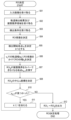
- FIG. 5 shows a flow chart of the operation of the within-gauge obstacle detection system 10 .
- the image acquisition unit 101 receives an input image from an external camera.
- the trajectory detection unit 103 detects the trajectory in the input image.
- the trajectory may be detected by image processing, or the coordinates of the trajectory in the input image may be calculated from GPS or map data. Since the track extends from the tip of the railway vehicle, it can be easily detected in comparison with obstacles and the like.
- the track coordinates indicate, for example, the centerline between the left and right rails. As described above, the upper left corner of the input image is the origin, the vertical direction is the v coordinate, and the horizontal direction is the u coordinate.
- the trajectory coordinates indicate the u and v coordinates of each point on the centerline. For example, v coordinate values increase from top to bottom of the image, and u coordinate values increase from left to right.
- the construction gauge area determination unit 104 determines the construction gauge.
- the construction gauge is composed of two construction gauge lines, and the area determined by the construction gauge lines is the construction gauge area.
- the construction gauge area is an area centered on the u-coordinate of the track and having a width that is a constant multiple of the track width. If the construction gauge width in the real world is L [m] and the track width in the real world is R [m], the constant is L/R.
- the value of L is preset and stored in the management information database 120, for example.
- the detection condition determination unit 102 determines the detection conditions by the method described above.
- the detection condition determination unit 102 determines the detection target, object detection model, required detection accuracy, track width, weather, and time zone.
- step 505 the ROI processing unit 106 determines a sufficient number and size of ROIs based on the detection results of the trajectory and construction gauge area in step 502 and the detection conditions determined in step 503. Details of the processing of the ROI processing unit 106 in step 505 will be described later.
- step 506 the obstacle detection unit 107 performs obstacle detection processing on all ROIs. If an obstacle is detected (507: YES), the flow proceeds to step 508; At step 508, the result output unit 108 issues an obstacle detection alert.
- the result output unit 108 may issue a warning to the driver when the human interface for the driver can be operated, or perform deceleration processing of the vehicle when connected to the operation control device of the railway vehicle.
- step 508 the flow proceeds to step 509. If no obstacle is detected in step 506 (507: NO), the flow proceeds to step 509; At step 509, the image acquisition unit 101 determines whether there is an input image to be processed next. If there is a next input image to process (509: YES), flow returns to step 501 and the next input image is received. If there is no input image to be processed next (509: NO), this process ends.
- FIG. 6 shows a flowchart of processing by the ROI processing unit 106 in step 505 .
- the image input unit 301 receives an input image.
- An input image is an image as shown in FIG. 2, for example.
- the trajectory detection result input unit 302 receives the trajectory detection result from the trajectory detection unit 103 . Furthermore, the construction gauge area input unit 305 receives information on the construction gauge area from the construction gauge area determination unit 104 . At step 603 , the detection condition input unit 303 receives detection conditions from the detection condition determination unit 102 .
- the ROI coefficient determination unit 304 determines ROI coefficients. Specifically, the ROI coefficient determination unit 304, in accordance with the detection conditions acquired from the detection condition input unit 303, determines the coefficient table 410 for the detection object, the coefficient table 420 for the obstacle detection model and detection accuracy, the coefficient for the track width. Coefficients are obtained from table 430 and weather and time of day coefficients table 440 . The ROI coefficient determination unit 304 calculates the product of the acquired coefficient and a predetermined constant as the ROI coefficient.
- the ROI determination unit 306 determines the v-coordinate v1 of the detection start point in the input image.
- v 1 is the v-coordinate of the farthest point from the vehicle in the point to be monitored. That is, it is the highest monitored point in the image and the minimum value of the v coordinates of the monitored point.
- An example of a method for determining v 1 is to set v 1 to the farthest point from the vehicle in the coordinates of the detected track (coordinates of the center line of the track).
- Another example may determine v 1 based on the braking distance calculated from the travel speed of the railcar. Here, 1 is substituted for the variable k.
- the ROI determining unit 306 multiplies the ROI coefficient by the width w k of the trajectory at the v-coordinate v k in the screen to determine the width r k of ROI k , which is the k-th ROI. do.
- the ROI is assumed to be square.
- the v coordinate of the upper side of ROI k is v k .
- v k is the reference ordinate value of ROI k .
- the ROI determining unit 306 searches for a point (position) where ROI k cannot cover the construction gauge area, that is, the point where the construction gauge area first deviates from ROI k .
- v k +1 be the v coordinate of that point.
- the ROI determining unit 306 determines which of the above four patterns applies to ROI k from the relationship between ROI k and the trajectory in the image.
- the point where the construction gauge area deviates from ROI k depends on the shape and position of ROI k . As described above, the length r k of one side of ROI k and the v coordinate v k of the upper side have already been determined, and the u coordinate of ROI k is undetermined. The final u coordinates of ROI k are determined in step 608, described below.
- the ROI determination unit 306 adjusts the u-coordinate of ROI k to determine which of the patterns described above corresponds.
- FIG. 7 schematically shows a first pattern in which ROI k cannot cover the construction gauge area.
- both of the two construction gauge lines intersect the upper and lower edges of ROI k .
- a trajectory 210 extends from the front to the front. That is, the trajectory 210 extends from the bottom to the top of the input image.
- the u coordinate increases from left to right and the v coordinate increases from top to bottom.
- FIG. 7 shows two consecutive ROIs, the previous ROI k and the next ROI k+1 .
- the two construction gauge lines 220A, 220B of the trajectory 210 intersect the upper and lower sides of ROI k , respectively.
- the center C k of trajectory 210 at the upper edge of ROI k has coordinates (u k ,v k ).
- trajectory 210 has width w k and the building gauge region has width l k .
- ROI k has width r k .
- the two lower intersections of the construction gauge lines 220A, 220B with ROI k are both on the lower side of ROI k . Therefore, the v-coordinate of the point where ROI k cannot cover the construction gauge area is the v-coordinate of the lower side of ROI k .
- the v coordinate of the point where the ROI k cannot cover the construction gauge area is the v coordinate v k+1 of the upper side of the next ROI k+1 .
- the v-coordinate v k+1 of the upper side of the next ROI k+ 1 matches the v-coordinate (v k +r k ) of the lower side of ROI k .
- the intersection C k+ 1 between the upper edge of ROI k+1 and the centerline of trajectory 210 has coordinates (u k+1 , v k+1 ).
- trajectory 210 has width w k+1 and the construction gauge area has width l k+1 .
- ROI k+1 has width r k+1 .
- the relationship l k+1 (L/R)w k+1 holds.
- FIG. 8 schematically shows a second pattern in which ROI k cannot cover the construction gauge area.
- the left construction gauge intersects the upper and left edges of ROI k .
- the right construction gauge intersects the upper and right sides of ROI k .
- the left construction gauge line 220A of the trajectory 210 intersects the upper side and the left side of ROI k .
- the right construction gauge line 220B of the trajectory 210 intersects the upper side and the right side of ROI k .
- trajectory 210 at the upper edge of ROI k has coordinates (u k ,v k ).
- trajectory 210 has width w k and the building gauge region has width l k .
- ROI k has width r k .
- the lower intersection of building gauge line 220A and ROI k is on the left side of ROI k
- the lower intersection of building gauge line 220B and ROI k is on the right side of ROI k .
- the v-coordinates of these lower intersection points are the same. Therefore, the v-coordinate of the point where the ROI k cannot cover the construction gauge area is the v-coordinate of the lower intersection of the construction gauge lines 220A and 220B and the ROI k .
- the v coordinate of the point where the ROI k cannot cover the construction gauge area is the v coordinate v k+1 of the upper side of the next ROI k+1 . That is, the v-coordinate v k+1 of the upper side of the next ROI k+ 1 coincides with the v-coordinates of these lower intersections.
- the intersection C k+ 1 between the upper edge of ROI k+1 and the centerline of trajectory 210 has coordinates (u k+1 ,v k+1 ).
- trajectory 210 has width w k+1 and the construction gauge area has width l k+1 .
- ROI k+1 has width r k+1 .
- the relationship l k+1 (L/R)w k+1 holds.
- the width l k+1 of the construction gauge area is the same as the width r k+1 of the ROI k+1 . That is, the position where the width l k+1 of the construction gauge area and the width r k+1 of the ROI k+1 are the same is the position where the ROI k cannot cover the construction gauge area.
- FIG. 9 schematically shows a third pattern in which ROI k cannot cover the construction gauge area.
- one of the left construction gauge or the right construction gauge intersects the upper and left or right edges of ROI k .
- the other of the left construction gauge or the right construction gauge intersects the upper and lower edges of ROI k .
- the trajectory 210 is highly curved.
- the left construction gauge line 220A of the trajectory 210 intersects the upper side and the left side of ROI k .
- the right construction gauge line 220B of the trajectory 210 intersects the upper and lower sides of ROI k .
- trajectory 210 at the upper edge of ROI k has coordinates (u k ,v k ).
- trajectory 210 has width w k and the building gauge region has width l k .
- ROI k has width r k .
- the lower intersection of building gauge line 220A and ROI k is on the left side of ROI k
- the lower intersection of building gauge line 220B and ROI k is on the lower side of ROI k
- the upper that is, the farther intersection point is the position of the point where the ROI k can no longer cover the construction gauge area.
- the v coordinate of the point where the ROI k cannot cover the construction gauge area is the v coordinate v k+1 of the upper side of the next ROI k+1 . That is, the v-coordinate v k+1 of the upper side of the next ROI k+ 1 is the v-coordinate of the upper, that is, the farther, intersection of the lower intersections of the two construction gauge lines. This point is the same for the first and second patterns.
- trajectory 210 has width w k+1 and the construction gauge area has width l k+1 .
- ROI k+1 has width r k+1 .
- the relationship l k+1 (L/R)w k+1 holds.
- the u-coordinate of the centerline of trajectory 210 changes significantly.
- the position at which the ROI k cannot cover the construction gauge area is the point where the width r k of the ROI k becomes insufficient with respect to the width of the construction gauge area, that is, (
- +(l k +l k +1 )/2) r k .
- the lower intersection point between one of the two construction gauge lines and ROI k is located on the right side or left side of ROI k , and the other of the two construction gauge lines and ROI k There is an abscissa value of ROI k such that the lower intersection point of ROI k lies on the lower edge of ROI k .
- Object detection processing is performed so that the upper intersection point of one of the two construction gauge lines and ROI k coincides with the upper angle of ROI k on the opposite side of the lower intersection point of one of the two construction gauge lines.
- the construction gauge area is defined by two construction gauge lines 220A, 220B.
- the ROI determining unit 306 selects the closer, ie, the larger v-coordinate, out of the two intersections between each construction gauge line and ROI k . Furthermore, the ROI determining unit 306 determines the farthest point of the selected intersections of the two construction gauge lines as the point where the ROI k can no longer cover the construction gauge area. That is, the abscissa value of the ROI is determined such that the highest position of the two lower intersections of the two construction gauge lines and the ROI is the lowest position in the image.
- a fourth pattern is a case where ROI k reaches the bottom edge of the screen and the entire construction gauge area in the input image is covered by ROI 1 to ROI k .
- the v-coordinate v k that measures the width of the trajectory is used as the v-coordinate value of the top edge of ROI k .
- the v-coordinate v k is the reference ordinate value of ROI k .
- the v-coordinate value of the top edge of ROI k may be different from v k , eg, above v k .
- the ROI determination unit 306 identifies points at which ROI k cannot cover the construction gauge area, and determines its pattern.
- the ROI determination unit 306 determines the center u coordinate of ROI k .
- the ROI determination unit 306 can determine the u coordinate of the center of ROI k according to the pattern in which ROI k cannot cover the construction gauge area.
- the ROI determination unit 306 determines the u coordinate of the trajectory center on the upper side (v coordinate v k ) of ROI k and the trajectory center on the lower side (v coordinate v k+1 ).
- the u coordinate of the center of ROI k is determined as the mean value of the u coordinate of . This ensures that the ROI k includes the entire construction gauge area from the v-coordinate v k to the v-coordinate v k+1 .
- ROI k in FIG. 7 satisfies this condition.
- the u-coordinate of the center of ROI k is determined so that the v-coordinates of the intersections of the two construction gauge lines and the left and right sides of ROI k are the same.
- the u coordinate of the center of ROI k coincides with the u coordinate of the center of the trajectory at v coordinate v k+1 .
- ROI k can include the entire building gauge area from v coordinate v k to v coordinate v k+1 .
- ROI k in FIG. 8 satisfies this condition.
- the ROI determination unit 306 determines (u k +l k /2 ⁇ r k /2 (when u k >u k+1 )) or (u k ⁇ l k /2+r k / 2 (when u k ⁇ u k+1 )) may be determined as the u-coordinate of the center of ROI k .
- ROI k can include the entire building gauge area from v coordinate v k to v coordinate v k+1 .
- One of the building gauge lines intersects the upper corner of ROI k .
- ROI k in FIG. 9 satisfies this condition.
- the ROI determination unit 306 determines the u coordinate of the center of the trajectory at v coordinate v k as the u coordinate of the center of ROI k . This allows ROI k to include the entire area of the building gauge area in the image.
- the u coordinate value of ROI k in each pattern may be determined by a method different from the above method.
- the u coordinate of the center of the trajectory at v coordinate v k may be determined as the u coordinate of the center of ROI k .
- step 610 the ROI determination unit 306 determines whether a point (v-coordinate vk +1 ) at which ROIk cannot cover the construction gauge area has been detected. If there is no point at which ROI k cannot cover the construction gauge area, that is, in the case of the fourth pattern ( 610 : NO), the flow proceeds to step 612 .
- the ROI output unit 307 outputs all ROIs. This completes the ROI determination process of step 505 in FIG.
- the ROI determination unit 306 sets k to 1. I'm adding Flow then returns to step 606 to determine the next ROI at the new location of v-coordinate v k .
- the construction gauge area in the input image is covered with one or more ROIs over the range of perspective.
- an object can be detected in each ROI with the necessary detection accuracy determined by the detection conditions.
- FIG. 10 shows an example of multiple ROIs formed for one input image.
- three ROIs are formed for the input image 20, and the three ROIs cover the entire construction gauge area in the input image 20.
- the three ROIs are ROI 1 , ROI 2 and ROI 3 .
- ROI 1 and ROI 2 are the ROIs of the second pattern described with reference to FIG. 8, and ROI 3 is the ROI of the fourth pattern.
- Each ROI indicates a detection limit at which objects can be detected within that region.
- the ROI determiner 306 determines the v-coordinate v 1 and the ROI coefficients of the first ROI, ROI 1 .
- the length of one side of ROI 1 is determined from the ROI coefficients and the trajectory width at v-coordinate v 1 .
- trajectory 210 has width w 1 and the construction gauge area has width l 1 .
- ROI 1 has a width r 1 .
- ROI determiner 306 adjusts the u coordinate of ROI 1 as necessary to determine the relationship between ROI 1 and the construction gauge.
- the relationship between ROI 1 and trajectory 210 is the second pattern.
- the left construction gauge line 220A of the trajectory 210 intersects the upper side and the left side of ROI1 .
- the right construction gauge line 220B of the trajectory 210 intersects the upper side and the right side of ROI1 .
- the u coordinate of the center of ROI 1 is determined so that the intersection of the construction gauge line 220A and ROI 1 and the lower intersection point of the construction gauge line 220B and ROI 1 have the same v coordinate.
- the v-coordinate of the point where ROI 1 can no longer cover the construction gauge area is the v-coordinate v 2 of the lower intersection of the construction gauge lines 220A, 220B and ROI k .
- the ROI determining unit 306 performs processing to form the next ROI 2 at the v coordinate v 2 .
- the formation of ROI 2 is similar to the formation of ROI 1 above.
- trajectory 210 has width w 2 and the construction gauge area has width l 2 .
- ROI 2 has a width r 2 .
- the construction gauge lines 220A and 220B intersect the left and right sides of the ROI 2 at the v-coordinate v 3 .
- ROI 3 is formed at v-coordinate v3 .
- the track 210 has a width w3 and the construction gauge area has a width l3 .
- ROI 3 has a width r 3 .
- the relationship between ROI 3 and the construction gauge area is the fourth pattern.
- the u coordinate of the center of ROI 3 is determined to coincide with the u coordinate of the center of trajectory 210 at v coordinate v 3 .
- the present invention is not limited to the above-described embodiments, and includes various modifications.
- the above embodiments have been described in detail for easy understanding of the present invention, and are not necessarily limited to those having all the described configurations.
- part of the configuration of one embodiment can be replaced with the configuration of another embodiment, and the configuration of another embodiment can be added to the configuration of one embodiment.
- each of the above configurations, functions, processing units, etc. may be realized by hardware, for example, by designing a part or all of them with an integrated circuit.
- each of the above configurations, functions, etc. may be realized by software by a processor interpreting and executing a program for realizing each function.
- Information such as programs, tables, and files that implement each function can be stored in a memory, a hard disk, a recording device such as an SSD (Solid State Drive), or a recording medium such as an IC card or SD card.
- control lines and information lines indicate what is considered necessary for explanation, and not all control lines and information lines are necessarily indicated on the product. In fact, it may be considered that almost all configurations are interconnected.
Landscapes
- Engineering & Computer Science (AREA)
- Physics & Mathematics (AREA)
- General Physics & Mathematics (AREA)
- Theoretical Computer Science (AREA)
- Multimedia (AREA)
- Computer Vision & Pattern Recognition (AREA)
- Mechanical Engineering (AREA)
- Geometry (AREA)
- Image Analysis (AREA)
- Train Traffic Observation, Control, And Security (AREA)
- Image Processing (AREA)
Priority Applications (1)
| Application Number | Priority Date | Filing Date | Title |
|---|---|---|---|
| EP22863934.0A EP4397564A4 (en) | 2021-08-31 | 2022-04-14 | OBJECT DETECTION SYSTEM AND OBJECT DETECTION METHOD |
Applications Claiming Priority (2)
| Application Number | Priority Date | Filing Date | Title |
|---|---|---|---|
| JP2021141404A JP7734534B2 (ja) | 2021-08-31 | 2021-08-31 | 対象物を検出するシステム及び対象物を検出する方法 |
| JP2021-141404 | 2021-08-31 |
Publications (1)
| Publication Number | Publication Date |
|---|---|
| WO2023032344A1 true WO2023032344A1 (ja) | 2023-03-09 |
Family
ID=85412071
Family Applications (1)
| Application Number | Title | Priority Date | Filing Date |
|---|---|---|---|
| PCT/JP2022/017760 Ceased WO2023032344A1 (ja) | 2021-08-31 | 2022-04-14 | 対象物を検出するシステム及び対象物を検出する方法 |
Country Status (3)
| Country | Link |
|---|---|
| EP (1) | EP4397564A4 (https=) |
| JP (1) | JP7734534B2 (https=) |
| WO (1) | WO2023032344A1 (https=) |
Families Citing this family (2)
| Publication number | Priority date | Publication date | Assignee | Title |
|---|---|---|---|---|
| JP2026002633A (ja) * | 2024-06-21 | 2026-01-08 | 株式会社日立製作所 | 障害物検知システム |
| KR102842712B1 (ko) * | 2024-11-08 | 2025-08-06 | 한국철도기술연구원 | 영상 기반의 실시간 선로 검출 방법 |
Citations (4)
| Publication number | Priority date | Publication date | Assignee | Title |
|---|---|---|---|---|
| JP2019181996A (ja) | 2018-04-02 | 2019-10-24 | 株式会社東芝 | 前方監視装置、支障物衝突回避装置及び列車制御装置 |
| JP2019206318A (ja) * | 2018-05-30 | 2019-12-05 | 日本信号株式会社 | 監視装置 |
| JP2021517537A (ja) * | 2018-05-01 | 2021-07-26 | レール ビジョン リミテッドRail Vision Ltd | 選択された関心領域に関する高サンプリングレートの動的選択のためのシステムおよび方法 |
| JP2021141404A (ja) | 2020-03-04 | 2021-09-16 | フォクレット合同会社 | コミュニケーションシステム、コンピュータプログラム、及び情報処理方法 |
Family Cites Families (3)
| Publication number | Priority date | Publication date | Assignee | Title |
|---|---|---|---|---|
| JP6381981B2 (ja) * | 2014-06-12 | 2018-08-29 | 西日本旅客鉄道株式会社 | 線路空間支障物検知システム |
| JP7086949B2 (ja) * | 2016-10-20 | 2022-06-20 | レール ビジョン リミテッド | 鉄道アプリケーションの衝突回避において物体および障害物を検出し分類するためのシステムおよび方法 |
| JP7316107B2 (ja) * | 2019-06-19 | 2023-07-27 | 日本信号株式会社 | 監視装置 |
-
2021
- 2021-08-31 JP JP2021141404A patent/JP7734534B2/ja active Active
-
2022
- 2022-04-14 WO PCT/JP2022/017760 patent/WO2023032344A1/ja not_active Ceased
- 2022-04-14 EP EP22863934.0A patent/EP4397564A4/en active Pending
Patent Citations (4)
| Publication number | Priority date | Publication date | Assignee | Title |
|---|---|---|---|---|
| JP2019181996A (ja) | 2018-04-02 | 2019-10-24 | 株式会社東芝 | 前方監視装置、支障物衝突回避装置及び列車制御装置 |
| JP2021517537A (ja) * | 2018-05-01 | 2021-07-26 | レール ビジョン リミテッドRail Vision Ltd | 選択された関心領域に関する高サンプリングレートの動的選択のためのシステムおよび方法 |
| JP2019206318A (ja) * | 2018-05-30 | 2019-12-05 | 日本信号株式会社 | 監視装置 |
| JP2021141404A (ja) | 2020-03-04 | 2021-09-16 | フォクレット合同会社 | コミュニケーションシステム、コンピュータプログラム、及び情報処理方法 |
Also Published As
| Publication number | Publication date |
|---|---|
| JP2023034917A (ja) | 2023-03-13 |
| JP7734534B2 (ja) | 2025-09-05 |
| EP4397564A4 (en) | 2025-07-02 |
| EP4397564A1 (en) | 2024-07-10 |
Similar Documents
| Publication | Publication Date | Title |
|---|---|---|
| EP4152204B1 (en) | Lane line detection method, and related apparatus | |
| US11352021B1 (en) | Systems and methods for interfacing with an occupant | |
| CN111727413B (zh) | 用于访问来自其他车辆的补充感知数据的方法 | |
| JP7349792B2 (ja) | 車両走行のための情報を提供する方法 | |
| JP7454685B2 (ja) | 車両走行路内のデブリの検出 | |
| CN110929655B (zh) | 一种行驶过程中车道线识别方法、终端设备及存储介质 | |
| US11042159B2 (en) | Systems and methods for prioritizing data processing | |
| JP2024023319A (ja) | 緊急車両の検出 | |
| KR102493930B1 (ko) | 강화학습 기반 신호 제어 장치 및 신호 제어 방법 | |
| CN112105890A (zh) | 用于自动驾驶车辆的基于rgb点云的地图生成系统 | |
| CN111752276A (zh) | 局部路径规划方法、装置、计算机可读存储介质及机器人 | |
| KR20200030305A (ko) | 영상 처리를 위한 학습 데이터 생성 방법, 영상 처리 방법, 및 그 장치들 | |
| CN106647776A (zh) | 车辆变道趋势的判断方法、判断装置和计算机存储介质 | |
| CN107705577B (zh) | 一种基于车道线标定车辆违章变道的实时检测方法及系统 | |
| CN114729810A (zh) | 人行横道检测 | |
| US20250285298A1 (en) | Speed estimation systems and methods without camera calibration | |
| CN109840454B (zh) | 目标物定位方法、装置、存储介质以及设备 | |
| WO2023032344A1 (ja) | 対象物を検出するシステム及び対象物を検出する方法 | |
| KR20210061069A (ko) | 3차원 객체를 표시하는 방법 및 장치 | |
| US20220161791A1 (en) | Motion planning in curvilinear coordinates for autonomous vehicles | |
| Janda et al. | Road boundary detection for run-off road prevention based on the fusion of video and radar | |
| CN114397882B (zh) | 一种航空器的泊位引导方法、装置、介质和无人引导车 | |
| JP2006350699A (ja) | 画像処理装置及び方法 | |
| KR20160015091A (ko) | 교통신호제어 시스템의 보행자 검출 및 행동패턴 추적 방법 | |
| CN111427331B (zh) | 无人驾驶车辆的感知信息展示方法、装置和电子设备 |
Legal Events
| Date | Code | Title | Description |
|---|---|---|---|
| 121 | Ep: the epo has been informed by wipo that ep was designated in this application |
Ref document number: 22863934 Country of ref document: EP Kind code of ref document: A1 |
|
| WWE | Wipo information: entry into national phase |
Ref document number: 2022863934 Country of ref document: EP |
|
| NENP | Non-entry into the national phase |
Ref country code: DE |
|
| ENP | Entry into the national phase |
Ref document number: 2022863934 Country of ref document: EP Effective date: 20240402 |