WO2023026930A1 - 照射プローブ - Google Patents
照射プローブ Download PDFInfo
- Publication number
- WO2023026930A1 WO2023026930A1 PCT/JP2022/031109 JP2022031109W WO2023026930A1 WO 2023026930 A1 WO2023026930 A1 WO 2023026930A1 JP 2022031109 W JP2022031109 W JP 2022031109W WO 2023026930 A1 WO2023026930 A1 WO 2023026930A1
- Authority
- WO
- WIPO (PCT)
- Prior art keywords
- optical fiber
- light
- radial direction
- intensity
- scattering region
- Prior art date
- Legal status (The legal status is an assumption and is not a legal conclusion. Google has not performed a legal analysis and makes no representation as to the accuracy of the status listed.)
- Ceased
Links
Images


Classifications
-
- A—HUMAN NECESSITIES
- A61—MEDICAL OR VETERINARY SCIENCE; HYGIENE
- A61N—ELECTROTHERAPY; MAGNETOTHERAPY; RADIATION THERAPY; ULTRASOUND THERAPY
- A61N5/00—Radiation therapy
- A61N5/06—Radiation therapy using light
-
- G—PHYSICS
- G02—OPTICS
- G02B—OPTICAL ELEMENTS, SYSTEMS OR APPARATUS
- G02B6/00—Light guides; Structural details of arrangements comprising light guides and other optical elements, e.g. couplings
- G02B6/0001—Light guides; Structural details of arrangements comprising light guides and other optical elements, e.g. couplings specially adapted for lighting devices or systems
- G02B6/0005—Light guides; Structural details of arrangements comprising light guides and other optical elements, e.g. couplings specially adapted for lighting devices or systems the light guides being of the fibre type
- G02B6/0008—Light guides; Structural details of arrangements comprising light guides and other optical elements, e.g. couplings specially adapted for lighting devices or systems the light guides being of the fibre type the light being emitted at the end of the fibre
-
- G—PHYSICS
- G02—OPTICS
- G02B—OPTICAL ELEMENTS, SYSTEMS OR APPARATUS
- G02B6/00—Light guides; Structural details of arrangements comprising light guides and other optical elements, e.g. couplings
- G02B6/0001—Light guides; Structural details of arrangements comprising light guides and other optical elements, e.g. couplings specially adapted for lighting devices or systems
- G02B6/0005—Light guides; Structural details of arrangements comprising light guides and other optical elements, e.g. couplings specially adapted for lighting devices or systems the light guides being of the fibre type
- G02B6/001—Light guides; Structural details of arrangements comprising light guides and other optical elements, e.g. couplings specially adapted for lighting devices or systems the light guides being of the fibre type the light being emitted along at least a portion of the lateral surface of the fibre
-
- A—HUMAN NECESSITIES
- A61—MEDICAL OR VETERINARY SCIENCE; HYGIENE
- A61N—ELECTROTHERAPY; MAGNETOTHERAPY; RADIATION THERAPY; ULTRASOUND THERAPY
- A61N5/00—Radiation therapy
- A61N5/06—Radiation therapy using light
- A61N2005/063—Radiation therapy using light comprising light transmitting means, e.g. optical fibres
-
- A—HUMAN NECESSITIES
- A61—MEDICAL OR VETERINARY SCIENCE; HYGIENE
- A61N—ELECTROTHERAPY; MAGNETOTHERAPY; RADIATION THERAPY; ULTRASOUND THERAPY
- A61N5/00—Radiation therapy
- A61N5/06—Radiation therapy using light
- A61N5/0613—Apparatus adapted for a specific treatment
- A61N5/062—Photodynamic therapy, i.e. excitation of an agent
Definitions
- the present invention relates to irradiation probes.
- Patent Document 2 since it is necessary to cover all areas except the area to be irradiated with light with a reflective element, there is a problem that the irradiation probe becomes thick.
- a scattering surface extending in the longitudinal direction is formed over the entire circumference of the flexible plastic fiber, and the light is diffused from the scattering surface.
- the scattering surface generates heat when irradiated with light, and the heat resistance limit of the fiber may be exceeded especially when irradiated with high-power light.
- one of the objects of the present invention is, for example, an irradiation device with an improved and novel configuration that can obtain higher directivity with a smaller diameter and can further reduce heat generation. to obtain a probe.
- the irradiation probe of the present invention is, for example, an irradiation probe provided with an optical fiber having a leaking section for outputting leaked light radially outward as at least a partial section in the longitudinal direction, wherein the optical fiber includes the leaking
- the section has a scattering region that scatters the light in a predetermined range in the circumferential direction of the optical fiber to generate the leaked light, and the intensity distribution of the leaked light in the circumferential direction in a cross section that intersects the axial direction of the leaky section. in which the intensity of the leaked light in two radial directions substantially antiparallel to each other is higher than the intensity of the leaked light in other radial directions.
- the intensity of the leaked light in one of the two radial directions substantially antiparallel to each other and the intensity of the leaked light in the other radial direction of the two radial directions substantially antiparallel to each other may be different from each other.
- the optical fiber may have, as an outer peripheral surface in the scattering region, a convex curved surface whose average radius of curvature in the scattering region is equal to or greater than the radius of a general region outside the scattering region.
- the optical fiber may have a plane that intersects the radial direction as an outer peripheral surface in the scattering region.
- the optical fiber may have a concave curved surface that is concave radially inward as an outer peripheral surface in the scattering region.
- the illumination probe is a delivery optical fiber that transmits light from a light source to the optical fiber, the delivery optical fiber being eccentric with respect to the optical fiber and having a core diameter smaller than the core diameter of the optical fiber. may be provided.
- the irradiation probe is provided at a position shifted in a first radial direction, which is one of the two radial directions, with respect to the leakage section, and reflects the leaked light traveling in the first radial direction.
- a reflective member may be provided.
- the scattering region may be provided at a position shifted in the first radial direction from the central axis of the optical fiber.
- the scattering region may be provided at a position shifted from the central axis of the optical fiber in a second radial direction, which is the other radial direction of the two radial directions.
- the reflecting member may be in contact with the scattering region or face it with a gap.
- the optical fiber has a second radial direction, which is another radial direction of the two radial directions, in the intensity distribution of the leaked light in the circumferential direction in a cross section that intersects the axial direction of the leakage section.
- the directionality may be such that the intensity of the leaked light in the direction is higher than the intensity of the leaked light in the first radial direction.
- reflected light from the reflecting member of the leaked light directed in the first radial direction may enter the optical fiber and be emitted from the optical fiber to the side opposite to the reflecting member.
- the reflecting member may have a shape recessed in the first radial direction.
- the reflecting member may protrude on both sides in the circumferential direction of the optical fiber with respect to the scattering region.
- the projection target portion projected by the projection light and when the projection light is projected in the radial direction of the irradiation probe, the projection shape by the projection light rotates around the central axis of the irradiation probe. It may have a projection target configured differently depending on the orientation.
- the projection target portions are spaced apart from each other in the longitudinal direction, and are spaced apart from each other in the circumferential direction of the irradiation probe at a central angle different from 0° or 180° when viewed in the longitudinal direction. It may have at least two parts that are aligned.
- the irradiation probe of the present invention is, for example, an irradiation probe provided with an optical fiber having a leaking section for outputting leaked light radially outward as at least a partial section in the longitudinal direction, wherein the optical fiber includes the leaking In the intensity distribution of the leaked light in the circumferential direction in a cross section that intersects with the axial direction of the section, the intensity of the leaked light in a specific radial direction is higher than the intensity of the leaked light in other radial directions. and a reflecting member that is offset in the specific radial direction with respect to the optical fiber and that reflects the leaked light.
- the irradiation probe of the present invention is, for example, an irradiation probe provided with an optical fiber having a leaking section for outputting leaked light radially outward as at least a partial section in the longitudinal direction, wherein the optical fiber includes the leaking In the intensity distribution of the leaked light in the circumferential direction in a cross section that intersects with the axial direction of the section, the intensity of the leaked light in two radial directions substantially antiparallel to each other is higher than the intensity of the leaked light in the other radial direction.
- the optical fiber has a reflecting member which has high directivity and which is shifted in one of the two substantially antiparallel radial directions with respect to the optical fiber and reflects the leaked light.
- an irradiation probe with an improved and novel configuration, such as a smaller diameter, higher directivity, and reduced heat generation. can.
- FIG. 1 is an exemplary schematic configuration diagram of an irradiation probe system according to an embodiment.
- FIG. 2 is an exemplary schematic cross-sectional view of an illumination probe of an embodiment.
- FIG. 3 is an exemplary schematic cross-sectional view of a portion of the optical fiber of the illumination probe of the embodiment.
- FIG. 4 is an exemplary block diagram of an embodiment illumination probe system.
- FIG. 5 is a schematic cross-sectional view of a modification of the scattering region of the irradiation probe of the embodiment.
- FIG. 6 is a schematic cross-sectional view of a modification of the scattering region of the irradiation probe of the embodiment.
- FIG. 7 is a schematic cross-sectional view of a modification of the scattering region of the irradiation probe of the embodiment.
- FIG. 8 is a schematic side view of a modification of the scattering region of the illumination probe of the embodiment;
- FIG. 9 is a schematic cross-sectional view of a modification of the scattering region of the irradiation probe of the embodiment.
- FIG. 10 is an exemplary and schematic cross-sectional view of an optical fiber according to a modification of the embodiment;
- FIG. 11 is an exemplary and schematic cross-sectional view of an optical fiber of a modified example of the embodiment.
- FIG. 12 is an exemplary schematic cross-sectional view of an optical fiber according to a modification of the embodiment;
- FIG. 13 is an exemplary schematic cross-sectional view of an optical fiber according to a modification of the embodiment;
- FIG. 14 is an exemplary schematic cross-sectional view of an optical fiber and a reflecting member in a modified example of the embodiment
- FIG. 15 is an exemplary schematic side view of a coupling portion between an optical fiber and a delivery optical fiber in a modified example of the embodiment
- FIG. 16 is an exemplary and schematic explanatory diagram of an end portion of an irradiation probe provided with a projection target portion according to a modification of the embodiment.
- 17A and 17B are exemplary and schematic explanatory diagrams of the end portion of the irradiation probe provided with the projection target portion of FIG. 16 and having different rotational postures about the central axis.
- FIG. 18 is an exemplary and schematic cross-sectional view of an irradiation probe of a reference example.
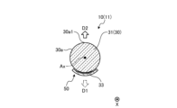
- the X direction is the axial direction (longitudinal direction) of the irradiation probe 10 and the optical fiber 30 .
- FIG. 1 is a schematic diagram of an irradiation probe system 1 according to an embodiment.
- the irradiation probe system 1 includes a light output device 100, an irradiation probe 10, a control device 200, a delivery optical fiber 20, and an input section 220.
- the light output device 100 has a light source unit 110 .
- the light source unit 110 has a light source that outputs laser light and an optical system that guides the light from the light source to the delivery optical fiber 20 (both not shown).
- the light source includes, for example, a laser element that outputs laser light.
- the light source unit 110 and the irradiation probe 10 are optically connected via the delivery optical fiber 20 .
- the irradiation probe 10 includes an optical fiber, has an elongated, substantially cylindrical and linear shape, and is flexible.
- the irradiation probe 10 also has an end portion 10a that is one end in the axial direction and an end portion 10b that is the other end in the axial direction.
- the end portion 10a is an input end into which light from the light source unit 110 is input, and can also be referred to as a base end.
- the end portion 10b is located on the opposite side of the end portion 10a in the axial direction and can also be referred to as a tip.
- the irradiation probe 10 has a leak section 11 and a transmission section 12 .
- the leaking portion 11 is provided over a predetermined length in the axial direction at a position away from the end portion 10a, and is a section that leaks light radially outward from the outer peripheral surface 10c of the irradiation probe 10. As shown in FIG. The leaked light from the outer peripheral surface 10 c as the side surface of the leaking portion 11 is the irradiated light from the irradiation probe 10 .
- the transmitting portion 12 may be provided between the end portion 10a and the leaking portion 11, between the leaking portion 11 and the end portion 10b, or when a plurality of leaking portions 11 are provided at intervals in the axial direction.
- the leak portion 11 is provided only in a section adjacent to the end portion 10b, but is not limited to this, and may be provided apart from the end portion 10b.
- the control device 200 can control the light source unit 110, for example, to output light or stop outputting light.
- the control device 200 can also control the operation of devices and parts other than the light source unit 110 in the irradiation probe system 1 .
- the input unit 220 constitutes a user interface operated by an operator (user), and inputs an instruction signal to the control device 200 according to the operator's operation input.
- the control device 200 is an example of a control mechanism, and the input section 220 is an example of an operation input section.
- FIG. 2 is a cross-sectional view of the leakage portion 11 of the irradiation probe 10.
- the illumination probe 10 has the optical fiber 30 and the reflective member 50 shown in FIG. 2 and a coating (not shown) surrounding the optical fiber 30 and the reflective member 50 .
- the coating is transparent to light transmitted by the optical fiber 30 .
- the optical fiber 30 is optically connected with the delivery optical fiber 20 .
- the optical fiber 30 and the delivery optical fiber 20 may be directly connected by fusion splicing or the like or indirectly via a coupling portion or the like. It may be made from fiber.
- the optical fiber 30 has a core 31 and a clad (not shown) surrounding the core 31 .
- the optical fiber 30 has a core 31 and a clad.
- the cladding is substantially removed from each optical fiber 30, and only the core 31 exists. That is, in the example of FIG. 2 , the outer peripheral surface 30 a of each optical fiber 30 is the outer peripheral surface of the core 31 .
- a scattering region 33 for scattering light is provided in at least one of the outer peripheral surface 30a and a predetermined depth range in the vicinity of the outer peripheral surface 30a.
- the scattering region 33 extends in the circumferential direction. Specifically, as shown in FIG. 2, the scattering region 33 is a partial section in the circumferential direction, specifically, a predetermined central angle (in FIG. 2, , as an example, 60 deg) or a range in the vicinity thereof.
- the scattering region 33 also extends in the axial direction (longitudinal direction). In other words, the scattering region 33 is provided over a predetermined lengthwise section in the leaking portion 11 .
- the scattering region 33 may be provided all over the leaking portion 11 , may be provided in a part of the leaking portion 11 , or may be intermittently provided at a plurality of locations of the leaking portion 11 . Note that when a plurality of scattering regions 33 are provided in the leaking portion 11, the scattering regions 33 are provided so as to line up in the longitudinal direction.
- the section provided with the scattering region 33 is an example of a leaky section.
- the leak section is included in the leak section 11 . In other words, the leaky section of the optical fiber 30 in which the scattering region 33 is provided is part of the component of the leaky portion 11 of the illumination probe 10 .
- FIG. 3 is a cross-sectional view of the optical fiber 30 at the site where the scattering region 33 is provided.
- the outer peripheral surface 30a is provided with a plurality of recesses 33a.
- the light transmitted through the core 31 is refracted and scattered at the concave portion 33a and leaks out of the core 31, that is, out of the optical fiber 30 from the outer peripheral surface 30a.
- the recesses 33a are provided discretely, and the size and depth of the recesses 33a are not constant.
- the plurality of recesses 33a may be arranged regularly, or the specifications such as the size, depth, and shape of the plurality of recesses 33a may be substantially constant.
- the outer peripheral surface 30a may be provided with convex portions instead of the concave portions 33a.
- the protrusion may be, for example, a portion between the recesses 33a.
- the concave portion 33a and the convex portion facilitate the leakage of light from the core 31 to the outside in the radial direction.
- the distribution of the light leakage intensity in the axial direction and the circumferential direction of the leaking portion 11 is appropriately adjusted. can do.
- the average curvature radius of the scattering regions 33 is the same as the radius of the general region of the outer peripheral surface 30a of the optical fiber 30 where the scattering regions 33 are not formed.
- the outer peripheral surface 30a is a convex curved surface.
- the intensity distribution of the leaked light in the circumferential direction in the cross section that intersects the axial direction of the optical fiber 30 has the central axis Ax of the optical fiber 30
- the intensity of leaked light in a specific radial direction (outside in the radial direction) from the optical fiber is higher than the intensity of leaked light in other radial directions, that is, an optical fiber having directivity.
- the intensity of leaked light in the radial directions D1 and D2 is higher than the intensity in other radial directions.
- the radial direction D1 and the radial direction D2 are different radial directions and substantially anti-parallel directions, that is, substantially opposite directions. Further, by appropriately configuring the scattering region 33, it is possible to make the intensity of the leaked light in the radial direction D1 and the intensity of the leaked light in the radial direction D1 different from each other.
- the radial directions D1 and D2 are examples of specific radial directions.
- the specific radial direction is defined as the radial direction in which the intensity distribution of the leaked light from the optical fiber 30 in the circumferential direction of the optical fiber 30 has a peak.
- radial directions for example, two directions
- each of them is assumed to be a specific radial direction.
- a reflecting member 50 is provided. As shown in FIG. 2 , the reflecting member 50 is shifted in the radial direction D1 with respect to the optical fiber 30 . That is, in the present embodiment, both the scattering region 33 and the reflecting member 50 are shifted in the radial direction D1, that is, in the same radial direction, with respect to the central axis Ax.
- the reflecting member 50 reflects scattered light incident on the reflecting member 50 . Therefore, the irradiation probe 10 does not output leakage light, ie, irradiation light, in the radial direction D1.
- the radial direction D1 is an example of a first radial direction.
- the reflecting member 50 includes, for example, a metal member and reflects light leaking from the optical fiber 30 .
- the reflecting member 50 includes a body made of a material such as a synthetic resin material that is softer than a metal material, and a reflective material such as a metal material that covers the surface of the body on the optical fiber 30 side. and a reflective layer fabricated.
- part of the light (scattered light) scattered in the scattering region 33 and directed in the radial direction D2 of the optical fiber 30 is transferred to the surface of the optical fiber 30 opposite to the scattering region 33 The light is totally reflected at the surface 30a1) and remains in the optical fiber 30.
- FIG. Another part of the light scattered in the scattering region 33 and directed in the radial direction D2 of the optical fiber 30 does not satisfy the total reflection condition at the opposing surface 30a1 and leaks out of the optical fiber 30 from the opposing surface 30a1. and head toward the radial direction D2 or a direction close to the radial direction D2.
- most of the scattered light in the scattering region 33 is selectively emitted out of the optical fiber 30 from the opposing surface 30a1, that is, leaks out of the optical fiber 30.
- the reflecting member 50 has a shape recessed in the radial direction D1. Thereby, the reflecting member 50 functions as a concave mirror, the convergence of the reflected light in the radial direction D2 is enhanced, and the directivity of the irradiation probe 10 in the radial direction D2 can be further enhanced.
- the radius of curvature of the reflecting surface of the reflecting member 50 may be the same as or different from the radius of the outer peripheral surface 30a.
- the reflecting member 50 protrudes on both sides of the scattering area 33 in the circumferential direction. Furthermore, the reflecting member 50 is in contact with the scattering region 33 or faces it with a minute gap. As a result, the ratio of the scattered light from the scattering region 33 directly leaking out of the optical fiber 30 is reduced, in other words, the ratio of the scattered light in the scattering region 33 leaking out of the optical fiber 30 via the facing surface 30a1. is made higher, the directivity of the irradiation probe 10 in the radial direction D2 can be more easily increased.
- the optical fiber 30 can reduce the intensity of the leaked light in the radial direction D2 rather than the intensity of the leaked light in the radial direction D1. It is preferable to have directivity in which the intensity of light is high. As a result, for example, there is an advantage that heat generation in the reflecting member 50 can be suppressed.
- the reflecting member 50 can be configured relatively narrow (small) along a relatively short range of the outer periphery of the optical fiber 30, so that the irradiation probe 10 can be configured thinner. You also get benefits.
- the scattering region may generate heat when irradiated with light.
- the area of the heat generating portion per unit volume of the fiber can be reduced, thereby suppressing heat generation. can do.
- FIG. 4 is a block diagram of the illumination probe system 1.
- the irradiation probe system 1 includes a control device 200, an input section 220, and an output section 230.
- the input unit 220 and the output unit 230 construct a user interface for users and operators.
- the input unit 220 is, for example, an input device such as a remote controller, an operation unit such as a switch box or joystick, a keyboard, a touch panel, a mouse, a switch, or an operation button.
- the output unit 230 is, for example, a display, a printer, a lamp, a speaker, or the like, and is an output device for images, printing, and sound.
- the control device 200 also has a controller 210 , a main storage unit 241 and an auxiliary storage device 242 .
- the controller 210 is, for example, a processor (circuit) such as a CPU (central processing unit).
- the main storage unit 241 is, for example, RAM (random access memory) or ROM (read only memory).
- the auxiliary storage device 242 is, for example, a non-volatile rewritable storage device such as an SSD (solid state drive) or HDD (hard disk drive).
- the controller 210 operates as an irradiation control unit 211, an input control unit 212, and an output control unit 213 by reading programs stored in the main storage unit 241 and the auxiliary storage device 242 and executing each process.
- the program can be provided as an installable file or an executable file recorded on a computer-readable recording medium.
- a recording medium may also be referred to as a program product.
- Values used in arithmetic processing by programs and processors, information such as maps and tables may be stored in advance in the main storage unit 241 and auxiliary storage device 242, or may be stored in the storage unit of a computer connected to a communication network. and stored in the auxiliary storage device 242 by being downloaded via the communication network.
- Auxiliary storage device 242 stores data written by the processor.
- the computational processing by controller 210 may be performed, at least in part, by hardware.
- the controller 210 may include, for example, an FPGA (field programmable gate array) or an ASIC (application specific integrated circuit).
- the irradiation control section 211 can control the light output and output stop of the light source unit 110 included in the light output device 100 according to the operator's operation input to the input section 220 .
- the input control section 212 receives an input signal from the input section 220 . Further, the input control section 212 may control the input section 220 so that a predetermined operation input is possible.
- the output control unit 213 controls the output unit 230 to perform a predetermined output.
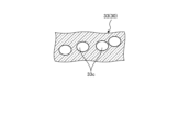
- FIG. 5 and 6 are cross-sectional views each showing an example of the configuration of the scattering region 33.
- FIG. The inside of the optical fiber 30 in which the scattering region 33 is formed contains particles 33b in the example of FIG. 5, and holes 33c in the example of FIG.
- the particles 33b and the holes 33c may be nanostructures with a diameter of 100 [nm] or less, for example.
- Particles 33b may be, for example, microparticles or fillers such as microtubes. In these cases, the traveling direction of the light is changed by the particles 33b and the holes 33c, that is, the light is scattered, so the light tends to leak outward in the radial direction from the outer peripheral surface 30a.
- Particles 33b and holes 33c may also be referred to as scattering elements.
- FIG. 7 is a cross-sectional view showing another example of the configuration of the scattering region 33.
- the outer peripheral surface 30a of the optical fiber 30 is inclined with respect to the X direction, which is the longitudinal direction of the optical fiber 30 .
- the outer peripheral surface 30a is, for example, a tapered surface. In this manner, at a portion where the shape of the outer peripheral surface 30a changes in the X direction, for example, light is incident on the portion exceeding the critical angle, so light tends to leak radially outward from the outer peripheral surface 30a. .
- FIG. 8 is a side view showing another example of the configuration of the scattering region 33.
- the scattering region 33 is curved. Light leaks easily from the bent portion. That is, even with the configuration of FIG. 8, light tends to leak radially outward from the outer peripheral surface 30a.
- FIG. 9 is a cross-sectional view showing another example of the configuration of the scattering region 33.
- the scattering region 33 has a coating layer 32 that at least partially covers the outer peripheral surface 31 a of the core 31 .
- the refractive index of the coating layer 32 is set to be substantially the same as or slightly higher than the refractive index of the core 31 .
- the coating layer 32 also contains scattering elements 33d such as particles and voids. In this case, light reaching the interface between the core 31 and the coating layer 32 enters the coating layer 32, is scattered by the scattering elements 33d, and leaks radially outward.
- the coating layer 32 by providing the coating layer 32, it is possible to appropriately set or change the location where light leaks, the location where light leaks easily, or the location where the intensity of leaked light increases. You get the advantage of being able to Further, when the core 31 is appropriately pressurized radially inward by the coating layer 32, light tends to leak from the pressurized portion.
- FIGS. 5 to 9 may be combined as appropriate in the optical fiber 30 and implemented.
- FIG. 10 is a cross-sectional view of the optical fiber 30 showing a modification of the scattering region 33.
- the average curvature radius of the outer peripheral surface 30a in the scattering region 33 is larger than the radius of the general region of the outer peripheral surface 30a of the optical fiber 30 where the scattering region 33 is not formed.
- the outer peripheral surface 30a is a convex curved surface.
- FIG. 11 is a cross-sectional view of the optical fiber 30 showing a modification of the scattering region 33.
- the outer peripheral surface 30a in the scattering region 33 is a plane that intersects the radial direction of the optical fiber 30 .
- FIG. 12 is a cross-sectional view of the optical fiber 30 showing a modification of the scattering region 33.
- the outer peripheral surface 30 a of the scattering region 33 is a concave curved surface that is concave radially inward of the optical fiber 30 .
- the ratio of the second scattered light to the first scattered light is hereinafter referred to as the branching ratio.
- the radial direction D2 is an example of a second radial direction.
- the magnitude of the branching ratio can be adjusted by adjusting various specifications of the scattering region 33 such as the radius of curvature and the length of the scattering region 33 in the circumferential direction. As a result, for example, the effect of increasing the degree of freedom in designing the irradiation probe 10 can be obtained.
- the scattering elements in the scattering region 33 are concave portions 33a (see FIG. 3) or convex portions provided on the outer peripheral surface 30a, and particles 33b ( 5) or holes 33c (see FIG. 6) or the like.
- the outer peripheral surface 30a of the optical fiber 30 is masked except for the portion where the scattering region 33 is to be formed, and the unmasked opening portion is sandblasted.
- the concave portion 33a and the convex portion can be formed by applying a process for forming an uneven surface such as the above.
- the shape and radius of curvature of the scattering region 33 can be appropriately adjusted by performing masking in multiple stages or by adjusting the irradiation time depending on the irradiation direction of sandblasting.
- FIG. 13 is a cross-sectional view of the optical fiber 30 showing a modification of the scattering region 33.
- the scattering region 33 is formed as a covering layer 32 as shown in FIG. Note that the coating layer 32 can be configured as part of a thin clad layer. Even in such a configuration, the same actions and effects as the examples of FIGS. 2 and 10-12 can be obtained.
- FIG. 14 is a cross-sectional view of the optical fiber 30 showing a modification of the reflecting member 50.
- the reflective member 50 is configured as a sleeve 55 that partially covers and extends longitudinally around the optical fiber 30 at the leakage portion 11 .
- the sleeve 55 is provided with a slit-like opening 50a that opens in the radial direction D1 and extends in the longitudinal direction.
- the reflecting member 50 can also be implemented in various forms.
- the size of the reflecting member 50 can be minimized and the radiated light can have directivity. This configuration is particularly suitable for realizing a small-diameter irradiation probe.
- [Configuration example (modification) of coupling part] 15 is a side view of the coupling portion 13 between the delivery optical fiber 20 and the optical fiber 30.
- FIG. 15 the core 21 of the delivery optical fiber 20 and the core 31 of the optical fiber 30 are shown, and the clad surrounding the cores 21 and 31 is omitted.
- the central axis Axd of the core 21 of the delivery optical fiber 20 is shifted from the central axis Ax of the core 31 of the optical fiber 30 .
- the delivery optical fiber 20 and the optical fiber 30 are eccentric.
- the diameter Dd of the core 21 of the delivery optical fiber 20 is smaller than the diameter Df of the core 31 of the optical fiber 30 , and the entire end surface 21 a of the core 21 faces the end surface 31 b of the core 31 .
- the branching ratio can be adjusted by changing the amount of eccentricity between the central axes Axd and Ax.
- the coupling portion 13 may be provided between the transmission portion 12 and the leakage portion 11 of the irradiation probe 10 . That is, the coupling portion 13 may be provided at a connection portion between the optical fiber 30 in the transmission portion 12 and the optical fiber 30 in the leakage portion 11 .
- the optical fiber 30 in the transmission section 12 is an example of a delivery optical fiber.
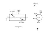
- FIG. 16 and 17 are a side view (left side) and a front view (right side) of a modification of the end portion 10b of the irradiation probe 10.
- FIG. FIG. 16 and FIG. 17 differ in the rotational attitude of the irradiation probe 10 around the central axis Ax.
- markers 57-1 and 57-2 made of metal members or the like are placed on the outer peripheral surface 40a of the mounting member 40 attached to the optical fiber 30 (not shown in FIG. 16) at the end 10b. is provided.
- the mounting member 40 is transparent to projection light such as X-rays, and the markers 57-1 and 57-2 are opaque to projection light.
- projection images Im can be obtained for these markers 57-1 and 57-2.
- the plurality of markers 57-1 and 57-2 are arranged so that the rotational orientation of the irradiation probe 10 about the central axis Ax can be determined from the projection image Im when the projection light is irradiated from the side along the radial direction. is set.
- the markers 57-1 and 57-2 are examples of projected portions.
- At least two portions to be projected are separated from each other in the longitudinal direction of the irradiation probe 10 and separated from each other in the circumferential direction of the irradiation probe 10 with a central angle different from 0° or 180° when viewed in the longitudinal direction. If there is a part, the projection shape of the projected part will change according to the rotational posture. If the central angles are 0° and 180°, the width of the projection shape becomes too narrow for both of these two parts, and there is a possibility that a rotation posture in which the projection shape cannot be obtained is generated, so they are excluded.
- the two markers 57-1 and 57-2 provided on the mounting member 40 are separated from each other in the X direction (longitudinal direction).
- the two markers 57-1 and 57-2 are separated from the central axis Ax in the radial direction, and as shown on the right side of FIGS. are circumferentially spaced from each other with a central angle of Therefore, in the examples of FIGS. 16 and 17, the two markers 57-1 and 57-2 are an example of two parts that have the action and effect of being able to discriminate the rotational posture by lateral projection.
- different projection images Im are obtained according to the rotational orientations, including rotational orientations different from those shown in FIGS. Therefore, according to the examples of FIGS. 16 and 17, it is possible to relatively easily and accurately detect the rotational posture of the irradiation probe 10 using the mounting member 40 and the markers 57-1 and 57-2.
- the two portions on the markers 57-1 and 57-2 that are separated from each other are also separated from each other in the longitudinal direction and irradiated with a central angle different from 0° or 180° when viewed in the longitudinal direction. Since they are spaced apart from each other in the circumferential direction of the probe 10, they can serve as an example of two parts that have the action and effect of being able to determine the rotational posture by lateral projection.
- FIGS. 16 and 17 are merely examples, and the two parts and the projected part can be implemented in various forms.
- the two parts and the projected part can be provided on various parts and members such as the coating of the irradiation probe 10, the reflecting member 50, the clad of the optical fiber 30, and the outer peripheral surface 31a of the core 31.
- the shape, arrangement, size, etc. of the two parts and the projected part can also be set variously.
- the intensity of leaked light in two radial directions substantially antiparallel to each other is
- the irradiation probe 10 having directivity higher than the intensity of the light leaking into the beam can be realized with a relatively simple configuration.
- the directivity can be further enhanced by irradiating the scattered light (leakage light) through the facing surface 30a1 and re-inputting the reflected light from the reflecting member 50 to the optical fiber 30. .
- the irradiation probes may be two radially irradiating irradiation probes that do not have a reflecting member.
- the present invention can be used for irradiation probes.
- Control apparatus 210 Controller 211... Irradiation control part 212... Input control part 213... Output control part 220... Input part 230... Output part 241... Main storage part 242... Auxiliary storage device Ax ... central axis Axd ... central axis D1 ... radial direction (first radial direction) D2...Radial direction (second radial direction) Dd... Diameter Df... Diameter Im... Projected image X... Direction Y... Direction
Landscapes
- Physics & Mathematics (AREA)
- General Physics & Mathematics (AREA)
- Optics & Photonics (AREA)
- Health & Medical Sciences (AREA)
- Engineering & Computer Science (AREA)
- Biomedical Technology (AREA)
- Pathology (AREA)
- Nuclear Medicine, Radiotherapy & Molecular Imaging (AREA)
- Radiology & Medical Imaging (AREA)
- Life Sciences & Earth Sciences (AREA)
- Animal Behavior & Ethology (AREA)
- General Health & Medical Sciences (AREA)
- Public Health (AREA)
- Veterinary Medicine (AREA)
- Light Guides In General And Applications Therefor (AREA)
- Measurement Of The Respiration, Hearing Ability, Form, And Blood Characteristics Of Living Organisms (AREA)
Priority Applications (3)
| Application Number | Priority Date | Filing Date | Title |
|---|---|---|---|
| EP22861218.0A EP4393541A4 (en) | 2021-08-27 | 2022-08-17 | IRRADIATION PROBE |
| JP2023543849A JPWO2023026930A1 (https=) | 2021-08-27 | 2022-08-17 | |
| US18/587,093 US12306426B2 (en) | 2021-08-27 | 2024-02-26 | Radiation probe with radial scatter regions with various intensities |
Applications Claiming Priority (2)
| Application Number | Priority Date | Filing Date | Title |
|---|---|---|---|
| JP2021139394 | 2021-08-27 | ||
| JP2021-139394 | 2021-08-27 |
Related Child Applications (1)
| Application Number | Title | Priority Date | Filing Date |
|---|---|---|---|
| US18/587,093 Continuation US12306426B2 (en) | 2021-08-27 | 2024-02-26 | Radiation probe with radial scatter regions with various intensities |
Publications (1)
| Publication Number | Publication Date |
|---|---|
| WO2023026930A1 true WO2023026930A1 (ja) | 2023-03-02 |
Family
ID=85321940
Family Applications (1)
| Application Number | Title | Priority Date | Filing Date |
|---|---|---|---|
| PCT/JP2022/031109 Ceased WO2023026930A1 (ja) | 2021-08-27 | 2022-08-17 | 照射プローブ |
Country Status (4)
| Country | Link |
|---|---|
| US (1) | US12306426B2 (https=) |
| EP (1) | EP4393541A4 (https=) |
| JP (1) | JPWO2023026930A1 (https=) |
| WO (1) | WO2023026930A1 (https=) |
Citations (7)
| Publication number | Priority date | Publication date | Assignee | Title |
|---|---|---|---|---|
| JPS56242Y2 (https=) * | 1974-12-06 | 1981-01-07 | ||
| JP2005143576A (ja) * | 2003-11-11 | 2005-06-09 | Seikoh Giken Co Ltd | ハンドピース用光ファイバ、その製造方法、及びレーザ装置 |
| JP3675482B2 (ja) | 1994-09-09 | 2005-07-27 | カーディオフォーカス・インコーポレイテッド | 光線治療装置 |
| JP2011145520A (ja) * | 2010-01-15 | 2011-07-28 | Mitsubishi Cable Ind Ltd | 光ファイバ |
| WO2011105631A1 (ja) * | 2010-02-26 | 2011-09-01 | 学校法人慶應義塾 | 光化学反応により心筋組織の光線力学的アブレーションを行うカテーテル |
| JP5113400B2 (ja) | 2007-02-08 | 2013-01-09 | 株式会社フジクラ | 光ファイバ、光ファイバ装置及びバンドルファイバ |
| JP2015510142A (ja) * | 2012-01-31 | 2015-04-02 | アシメトリック メディカル リミテッド | 曲げによって放射線を発するように構成される光ファイバ |
Family Cites Families (31)
| Publication number | Priority date | Publication date | Assignee | Title |
|---|---|---|---|---|
| US4466697A (en) * | 1981-11-12 | 1984-08-21 | Maurice Daniel | Light dispersive optical lightpipes and method of making the same |
| US6102905A (en) | 1994-09-09 | 2000-08-15 | Cardiofocus, Inc. | Phototherapy device including housing for an optical element and method of making |
| US6423055B1 (en) | 1999-07-14 | 2002-07-23 | Cardiofocus, Inc. | Phototherapeutic wave guide apparatus |
| US5632767A (en) | 1994-09-09 | 1997-05-27 | Rare Earth Medical, Inc. | Loop diffusers for diffusion of optical radiation |
| US5908415A (en) | 1994-09-09 | 1999-06-01 | Rare Earth Medical, Inc. | Phototherapy methods and apparatus |
| US6572609B1 (en) | 1999-07-14 | 2003-06-03 | Cardiofocus, Inc. | Phototherapeutic waveguide apparatus |
| US6579285B2 (en) | 1994-09-09 | 2003-06-17 | Cardiofocus, Inc. | Photoablation with infrared radiation |
| US8025661B2 (en) | 1994-09-09 | 2011-09-27 | Cardiofocus, Inc. | Coaxial catheter instruments for ablation with radiant energy |
| US6168591B1 (en) | 1994-09-09 | 2001-01-02 | Cardiofocus, Inc. | Guide for penetrating phototherapy |
| US6558375B1 (en) | 2000-07-14 | 2003-05-06 | Cardiofocus, Inc. | Cardiac ablation instrument |
| US5637877A (en) | 1995-06-06 | 1997-06-10 | Rare Earth Medical, Inc. | Ultraviolet sterilization of instrument lumens |
| US6676656B2 (en) | 1994-09-09 | 2004-01-13 | Cardiofocus, Inc. | Surgical ablation with radiant energy |
| US5947959A (en) | 1994-09-09 | 1999-09-07 | Rare Earth Medical, Inc. | Phototherapeutic apparatus with diffusive tip assembly |
| US6270492B1 (en) | 1994-09-09 | 2001-08-07 | Cardiofocus, Inc. | Phototherapeutic apparatus with diffusive tip assembly |
| US5643253A (en) | 1995-06-06 | 1997-07-01 | Rare Earth Medical, Inc. | Phototherapy apparatus with integral stopper device |
| US6416531B2 (en) * | 1998-06-24 | 2002-07-09 | Light Sciences Corporation | Application of light at plural treatment sites within a tumor to increase the efficacy of light therapy |
| US20050234436A1 (en) | 1999-07-14 | 2005-10-20 | Cardiofocus, Inc. | Methods of cardiac ablation in the vicinity of the right inferior pulmonary vein |
| US8540704B2 (en) | 1999-07-14 | 2013-09-24 | Cardiofocus, Inc. | Guided cardiac ablation catheters |
| US7935108B2 (en) | 1999-07-14 | 2011-05-03 | Cardiofocus, Inc. | Deflectable sheath catheters |
| US9033961B2 (en) | 1999-07-14 | 2015-05-19 | Cardiofocus, Inc. | Cardiac ablation catheters for forming overlapping lesions |
| US8900219B2 (en) | 1999-07-14 | 2014-12-02 | Cardiofocus, Inc. | System and method for visualizing tissue during ablation procedures |
| US20050234437A1 (en) | 1999-07-14 | 2005-10-20 | Cardiofocus, Inc. | Deflectable sheath catheters with out-of-plane bent tip |
| US20050222558A1 (en) | 1999-07-14 | 2005-10-06 | Cardiofocus, Inc. | Methods of cardiac ablation employing a deflectable sheath catheter |
| US20040167503A1 (en) | 1999-08-25 | 2004-08-26 | Cardiofocus, Inc. | Malleable surgical ablation instruments |
| US20040147913A1 (en) | 1999-08-25 | 2004-07-29 | Cardiofocus, Inc. | Surgical ablation instruments with irrigation features |
| TWI249046B (en) * | 2004-12-20 | 2006-02-11 | Jin-Huei Li | Structure for generating optical fiber flower |
| US20140288541A1 (en) | 2011-12-04 | 2014-09-25 | Asymmetric Medical Ltd. | Lesion treatment device and methods for treating lesions |
| EP3021778B1 (en) | 2013-07-17 | 2018-09-05 | Asymmetric Medical Ltd. | Vessel sealing and cutting devices |
| US10649126B2 (en) * | 2013-10-18 | 2020-05-12 | L.E.S.S. Ltd | Holder and systems for waveguide-based illumination |
| JP7326021B2 (ja) * | 2019-05-16 | 2023-08-15 | 朝日インテック株式会社 | 光照射デバイス、及び、光照射システム |
| DE102021115485A1 (de) * | 2021-06-15 | 2022-12-15 | Schott Ag | Beleuchtungssystem mit einem Lichtleiter mit einem Diffusor-Element |
-
2022
- 2022-08-17 JP JP2023543849A patent/JPWO2023026930A1/ja active Pending
- 2022-08-17 EP EP22861218.0A patent/EP4393541A4/en active Pending
- 2022-08-17 WO PCT/JP2022/031109 patent/WO2023026930A1/ja not_active Ceased
-
2024
- 2024-02-26 US US18/587,093 patent/US12306426B2/en active Active
Patent Citations (7)
| Publication number | Priority date | Publication date | Assignee | Title |
|---|---|---|---|---|
| JPS56242Y2 (https=) * | 1974-12-06 | 1981-01-07 | ||
| JP3675482B2 (ja) | 1994-09-09 | 2005-07-27 | カーディオフォーカス・インコーポレイテッド | 光線治療装置 |
| JP2005143576A (ja) * | 2003-11-11 | 2005-06-09 | Seikoh Giken Co Ltd | ハンドピース用光ファイバ、その製造方法、及びレーザ装置 |
| JP5113400B2 (ja) | 2007-02-08 | 2013-01-09 | 株式会社フジクラ | 光ファイバ、光ファイバ装置及びバンドルファイバ |
| JP2011145520A (ja) * | 2010-01-15 | 2011-07-28 | Mitsubishi Cable Ind Ltd | 光ファイバ |
| WO2011105631A1 (ja) * | 2010-02-26 | 2011-09-01 | 学校法人慶應義塾 | 光化学反応により心筋組織の光線力学的アブレーションを行うカテーテル |
| JP2015510142A (ja) * | 2012-01-31 | 2015-04-02 | アシメトリック メディカル リミテッド | 曲げによって放射線を発するように構成される光ファイバ |
Non-Patent Citations (1)
| Title |
|---|
| See also references of EP4393541A4 |
Also Published As
| Publication number | Publication date |
|---|---|
| US20240192421A1 (en) | 2024-06-13 |
| JPWO2023026930A1 (https=) | 2023-03-02 |
| US12306426B2 (en) | 2025-05-20 |
| EP4393541A1 (en) | 2024-07-03 |
| EP4393541A4 (en) | 2025-06-25 |
Similar Documents
| Publication | Publication Date | Title |
|---|---|---|
| JP6829780B2 (ja) | 光免疫療法に使用するための光拡散装置 | |
| US9036158B2 (en) | Pattern projector | |
| JP5866122B2 (ja) | 接触感応装置 | |
| JP4165509B2 (ja) | 導光板及びバックライト装置 | |
| CN106104147B (zh) | 用于准直光的光学系统 | |
| EP3237968A1 (en) | Improved uv application device | |
| CN107072467A (zh) | 照明装置和内窥镜 | |
| CN104955372B (zh) | 光学成像用探头 | |
| JP4367054B2 (ja) | 導光板及びバックライト装置 | |
| CN114945541B (zh) | 包覆状态检测方法、包覆状态检测装置及光纤制造方法 | |
| WO2023026930A1 (ja) | 照射プローブ | |
| JP2004111384A (ja) | 導光板及びバックライト装置 | |
| JP6531583B2 (ja) | 光デバイス、光システム及び改札機 | |
| JP2015011715A (ja) | 回折光を利用して全内反射を行う導光板タッチデバイス | |
| WO2023026988A1 (ja) | 照射プローブおよび照射プローブシステム | |
| JP7789059B2 (ja) | 送受光プローブシステムおよび送受光プローブ | |
| WO2017179168A1 (ja) | 撮影装置 | |
| US11579081B2 (en) | Structure of optical sensor having light-emitting element and plurality of light-receiving elements | |
| JP2020034966A (ja) | 光学素子、光射出装置および画像表示システム | |
| CN113569597B (zh) | 物体纹路的采集装置及终端设备 | |
| CN223551928U (zh) | 滑环系统及医疗设备 | |
| JP4117984B2 (ja) | 光源装置 | |
| WO2016114103A1 (ja) | 光デバイス、光システム及び改札機 | |
| JP6422782B2 (ja) | タッチパネル装置 | |
| WO2024101288A1 (ja) | 光拡散装置 |
Legal Events
| Date | Code | Title | Description |
|---|---|---|---|
| 121 | Ep: the epo has been informed by wipo that ep was designated in this application |
Ref document number: 22861218 Country of ref document: EP Kind code of ref document: A1 |
|
| WWE | Wipo information: entry into national phase |
Ref document number: 2023543849 Country of ref document: JP |
|
| WWE | Wipo information: entry into national phase |
Ref document number: 2022861218 Country of ref document: EP |
|
| NENP | Non-entry into the national phase |
Ref country code: DE |
|
| ENP | Entry into the national phase |
Ref document number: 2022861218 Country of ref document: EP Effective date: 20240327 |