WO2023026834A1 - 規模拡張型スケーラブル電源システム - Google Patents
規模拡張型スケーラブル電源システム Download PDFInfo
- Publication number
- WO2023026834A1 WO2023026834A1 PCT/JP2022/030208 JP2022030208W WO2023026834A1 WO 2023026834 A1 WO2023026834 A1 WO 2023026834A1 JP 2022030208 W JP2022030208 W JP 2022030208W WO 2023026834 A1 WO2023026834 A1 WO 2023026834A1
- Authority
- WO
- WIPO (PCT)
- Prior art keywords
- drive signal
- circuit
- switching drive
- signal
- power conversion
- Prior art date
- Legal status (The legal status is an assumption and is not a legal conclusion. Google has not performed a legal analysis and makes no representation as to the accuracy of the status listed.)
- Ceased
Links
Images


Classifications
-
- H—ELECTRICITY
- H02—GENERATION; CONVERSION OR DISTRIBUTION OF ELECTRIC POWER
- H02M—APPARATUS FOR CONVERSION BETWEEN AC AND AC, BETWEEN AC AND DC, OR BETWEEN DC AND DC, AND FOR USE WITH MAINS OR SIMILAR POWER SUPPLY SYSTEMS; CONVERSION OF DC OR AC INPUT POWER INTO SURGE OUTPUT POWER; CONTROL OR REGULATION THEREOF
- H02M3/00—Conversion of DC power input into DC power output
- H02M3/02—Conversion of DC power input into DC power output without intermediate conversion into AC
- H02M3/04—Conversion of DC power input into DC power output without intermediate conversion into AC by static converters
- H02M3/10—Conversion of DC power input into DC power output without intermediate conversion into AC by static converters using discharge tubes with control electrode or semiconductor devices with control electrode
- H02M3/145—Conversion of DC power input into DC power output without intermediate conversion into AC by static converters using discharge tubes with control electrode or semiconductor devices with control electrode using devices of a triode or transistor type requiring continuous application of a control signal
- H02M3/155—Conversion of DC power input into DC power output without intermediate conversion into AC by static converters using discharge tubes with control electrode or semiconductor devices with control electrode using devices of a triode or transistor type requiring continuous application of a control signal using semiconductor devices only
- H02M3/156—Conversion of DC power input into DC power output without intermediate conversion into AC by static converters using discharge tubes with control electrode or semiconductor devices with control electrode using devices of a triode or transistor type requiring continuous application of a control signal using semiconductor devices only with automatic control of output voltage or current, e.g. switching regulators
- H02M3/158—Conversion of DC power input into DC power output without intermediate conversion into AC by static converters using discharge tubes with control electrode or semiconductor devices with control electrode using devices of a triode or transistor type requiring continuous application of a control signal using semiconductor devices only with automatic control of output voltage or current, e.g. switching regulators including plural semiconductor devices as final control devices for a single load
- H02M3/1584—Conversion of DC power input into DC power output without intermediate conversion into AC by static converters using discharge tubes with control electrode or semiconductor devices with control electrode using devices of a triode or transistor type requiring continuous application of a control signal using semiconductor devices only with automatic control of output voltage or current, e.g. switching regulators including plural semiconductor devices as final control devices for a single load with a plurality of power processing stages connected in parallel
-
- H—ELECTRICITY
- H02—GENERATION; CONVERSION OR DISTRIBUTION OF ELECTRIC POWER
- H02M—APPARATUS FOR CONVERSION BETWEEN AC AND AC, BETWEEN AC AND DC, OR BETWEEN DC AND DC, AND FOR USE WITH MAINS OR SIMILAR POWER SUPPLY SYSTEMS; CONVERSION OF DC OR AC INPUT POWER INTO SURGE OUTPUT POWER; CONTROL OR REGULATION THEREOF
- H02M1/00—Details of apparatus for conversion
- H02M1/0048—Circuits or arrangements for reducing losses
-
- H—ELECTRICITY
- H02—GENERATION; CONVERSION OR DISTRIBUTION OF ELECTRIC POWER
- H02M—APPARATUS FOR CONVERSION BETWEEN AC AND AC, BETWEEN AC AND DC, OR BETWEEN DC AND DC, AND FOR USE WITH MAINS OR SIMILAR POWER SUPPLY SYSTEMS; CONVERSION OF DC OR AC INPUT POWER INTO SURGE OUTPUT POWER; CONTROL OR REGULATION THEREOF
- H02M3/00—Conversion of DC power input into DC power output
- H02M3/02—Conversion of DC power input into DC power output without intermediate conversion into AC
- H02M3/04—Conversion of DC power input into DC power output without intermediate conversion into AC by static converters
- H02M3/10—Conversion of DC power input into DC power output without intermediate conversion into AC by static converters using discharge tubes with control electrode or semiconductor devices with control electrode
- H02M3/145—Conversion of DC power input into DC power output without intermediate conversion into AC by static converters using discharge tubes with control electrode or semiconductor devices with control electrode using devices of a triode or transistor type requiring continuous application of a control signal
- H02M3/155—Conversion of DC power input into DC power output without intermediate conversion into AC by static converters using discharge tubes with control electrode or semiconductor devices with control electrode using devices of a triode or transistor type requiring continuous application of a control signal using semiconductor devices only
- H02M3/156—Conversion of DC power input into DC power output without intermediate conversion into AC by static converters using discharge tubes with control electrode or semiconductor devices with control electrode using devices of a triode or transistor type requiring continuous application of a control signal using semiconductor devices only with automatic control of output voltage or current, e.g. switching regulators
- H02M3/158—Conversion of DC power input into DC power output without intermediate conversion into AC by static converters using discharge tubes with control electrode or semiconductor devices with control electrode using devices of a triode or transistor type requiring continuous application of a control signal using semiconductor devices only with automatic control of output voltage or current, e.g. switching regulators including plural semiconductor devices as final control devices for a single load
-
- H—ELECTRICITY
- H02—GENERATION; CONVERSION OR DISTRIBUTION OF ELECTRIC POWER
- H02M—APPARATUS FOR CONVERSION BETWEEN AC AND AC, BETWEEN AC AND DC, OR BETWEEN DC AND DC, AND FOR USE WITH MAINS OR SIMILAR POWER SUPPLY SYSTEMS; CONVERSION OF DC OR AC INPUT POWER INTO SURGE OUTPUT POWER; CONTROL OR REGULATION THEREOF
- H02M1/00—Details of apparatus for conversion
- H02M1/08—Circuits specially adapted for the generation of control voltages for semiconductor devices incorporated in static converters
- H02M1/088—Circuits specially adapted for the generation of control voltages for semiconductor devices incorporated in static converters for the simultaneous control of series or parallel connected semiconductor devices
Definitions
- the present invention relates to a power supply system having a plurality of power conversion circuits, and in particular to a scale expansion type scalable power supply system.
- Patent Document 1 describes a switching power supply device.
- a switching power supply device described in Patent Document 1 includes a plurality of pulse correctors.
- a plurality of pulse compensators generate individual pulse signals that drive a plurality of power conversion circuits. Multiple phases are realized by differentiating the phases of a plurality of individual pulse signals using a plurality of pulse correctors.
- Patent Document 2 describes a multiphase DCDC converter.
- a multiphase DCDC converter described in Patent Document 2 includes a plurality of delay circuits.
- a plurality of delay circuits delay the PWM drive signal output by the control circuit.
- the control circuit and the plurality of delay circuits supply the PWM drive signal and the delay-controlled PWM drive signal to the converter drive section connected to the respective subsequent stages. This realizes multi-phase driving.
- Patent Document 3 describes a DCDC converter.
- the DCDC converter of Patent Document 3 includes a phase controller.
- the phase controller detects the state of the DCDC converter and dynamically changes the number of driving phases.
- the phase controller gives the number of drive phases to the distributor, and the distributor distributes a plurality of pulse signals set to phase differences according to the number of drive phases from one pulse signal and gives them to the driver ICs. This realizes multi-phase driving.
- Patent Document 4 describes a power supply semiconductor device.
- the power supply semiconductor device described in Patent Document 4 includes a plurality of driving ICs with timers.
- a plurality of driving ICs with timers are connected in a ring and sequentially send trigger signals.
- a plurality of driving ICs with timers perform switching control while sequentially shifting the time based on this trigger signal. This realizes multi-phase driving.
- Patent Document 5 describes a multiphase DCDC converter.
- a multiphase DCDC converter described in Patent Document 5 includes a phase control section and a pulse distribution section.
- the phase control section sets the number of driving phases and gives it to the pulse distribution section.
- the pulse distributor distributes a plurality of pulses included in one drive signal into a plurality of drive signals according to the number of drive phases so that the pulses do not overlap. This realizes multi-phase driving.
- an object of the present invention is to provide a multi-phase power conversion circuit according to the number of power conversion circuits that can be driven without being limited by the number of drive outputs of a control IC, with a simple configuration, and capable of suppressing a decrease in power conversion efficiency.
- the object is to provide a scale expansion type scalable power supply system that realizes driving.
- the scale expansion type scalable power supply system of the present invention comprises a plurality of power conversion circuits, power management control circuits, and expansion control circuits.
- Each of the plurality of power conversion circuits includes an inductor, a power semiconductor circuit including a switching element that controls current flowing through the inductor, and a drive unit that drives the switching element.
- a power management control circuit generates a first digital switching drive signal for a first power semiconductor circuit in the plurality of power semiconductor circuits.
- the extended control circuit is electrically connected between the power management control circuit and a second power semiconductor circuit different from the first power semiconductor circuit in the plurality of power semiconductor circuits.
- the enhanced control circuit generates a second switching drive signal from the first digital switching drive signal and provides the second switching drive signal to the second power semiconductor circuit.
- the expansion control circuit has a voltage-time conversion circuit that sets a predetermined signal delay time for the first digital switching drive signal and generates the second switching drive signal.
- the voltage-time conversion circuit has a threshold signal conversion circuit that determines the signal delay time using the time constant of the CR circuit consisting of resistors and capacitors and the threshold voltage.
- the expansion control circuit uses the time constant of the CR circuit of the threshold signal conversion circuit to set the phase of the second analog switching drive signal that is the basis of the second switching drive signal.
- the expansion control circuit uses the threshold voltage of the threshold signal conversion circuit and the phase-set second analog switching signal to set the ON time width of the second switching drive signal to the first digital switching signal. Set the same as the ON time width of the drive signal.
- the expansion control circuit determines the number of the plurality of power conversion circuits by the total number of signals added to the first signal number of the first digital switching drive signal and the second signal number of the second switching drive signal.
- the first digital switching drive signal output from one power management control circuit generates a second switching drive signal that has a different phase and the same on-time width as the first digital switching drive signal.
- Multi-phase driving is realized by applying these first digital switching drive signal and second switching drive signal to respective power conversion circuits.
- the second switching drive signal is a signal obtained by delaying the first digital switching drive signal, the switching frequency is maintained without decreasing even if the number of power conversion circuits increases.
- the extended control circuit that generates the second switching drive signal is a CR circuit consisting of a resistor and a capacitor, it has a simple configuration.
- a simple configuration in which an extension circuit is connected to the control IC is possible, power consumption in the extension circuit is small, a decrease in power conversion efficiency can be suppressed, and the number of driving outputs of the control IC is limited. It is possible to provide a scale-expandable scalable power supply system that realizes multi-phase drive capable of expanding the scale of output power capacity by flexibly coping with an increase in current in accordance with the number of power conversion circuits to be driven.
- FIG. 1 is a circuit block diagram showing an example of a power supply system according to the first embodiment.
- FIG. 2 is a circuit diagram showing an example of the configuration of an extended control circuit according to the first embodiment;
- FIG. 3 is a waveform diagram showing an example of a switching drive signal and a gate voltage signal.
- FIGS. 4A and 4B are functional block diagrams showing an example of effectiveness of the power supply system according to the first embodiment of the present invention.
- FIG. 5 is a circuit block diagram showing an extended control circuit portion of the power supply system according to the second embodiment.
- FIG. 6 is a waveform diagram showing an example of a switching drive signal and a gate voltage signal.
- FIG. 7 is a circuit block diagram showing an extended control circuit portion of the power supply system according to the third embodiment.
- FIG. 8 is a waveform diagram showing an example of a switching drive signal and a gate voltage signal.
- FIG. 9 is a circuit block diagram showing an example of a power supply system according to the fourth embodiment.
- FIG. 10 is a waveform diagram showing an example of a switching drive signal and a gate voltage signal.
- FIG. 11 is a circuit block diagram showing an example of a power supply system according to the fifth embodiment.
- FIG. 12 is a waveform diagram showing an example of a switching drive signal and a gate voltage signal.
- a scale-expandable power supply system in the present application means a power supply system in which the number of power conversion circuits used for multiphase driving can be set to a desired number. For example, in order to achieve a desired output current value at a desired output voltage value with high efficiency, it means a power supply system that can be configured by appropriately setting the number of power conversion circuits required for the system. In addition, below, a scale expansion type power supply system is simply called a power supply system.
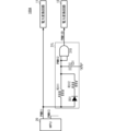
- FIG. 1 is a circuit block diagram showing an example of a power supply system according to the first embodiment.
- the power supply system 100 includes a plurality of power conversion circuits 11 to 14 (power conversion circuit 11, power conversion circuit 12, power conversion circuit 13, power conversion circuit 14), an MPU 20, and a plurality of extended control circuits. It includes circuits 31-32 (extension control circuit 31, extension control circuit 32). Although the number of power conversion circuits is four in this embodiment, the configuration of this embodiment can be applied as long as the number is two or more. Although the number of extended control circuits is two, it can be set according to the number of power conversion circuits and the number of digital switching drive signals that can be output from the MPU 20 with different phases.
- the power supply system 100 has a common input terminal Pin and a common output terminal Pout.
- the common input terminal Pin is connected to an external DC voltage source (input power supply).
- the power supply system 100 receives a DC input voltage Vin from a common input terminal Pin.
- a common output terminal Pout is connected to a load Ro. The voltage of the common output terminal Pout becomes the output voltage Vout of the power supply system 100 .
- the MPU 20 is connected to the common input terminal Pin and supplied with power through the common input terminal Pin.
- a regulator or the like is connected to the power input terminal of the MPU 20, and power is supplied through the regulator.
- This power supply line is connected to the ground reference potential through an input capacitor Ci1.
- the MPU 20 is a programmable Micro Processing Unit and is implemented by an IC or the like that implements a multiphase controller.
- the MPU 20 corresponds to the "power management control circuit" of the present invention.
- the MPU 20 is connected to the power conversion circuit 11 and the power conversion circuit 13.
- the input end of the extended control circuit 31 is connected to the connection line between the MPU 20 and the power conversion circuit 11 , and the output end of the extended control circuit 31 is connected to the power conversion circuit 12 .
- the input end of the extended control circuit 32 is connected to the connection line between the MPU 20 and the power conversion circuit 13 , and the output end of the extended control circuit 32 is connected to the power conversion circuit 14 .
- a plurality of power conversion circuits 11-14 are connected to a common input terminal Pin and supplied with power through the common input terminal Pin.
- a power supply line of the power conversion circuit 11 is connected to a ground reference potential through an input capacitor Ci1.
- the power supply line of the power conversion circuit 12 is connected to the ground reference potential through the input capacitor Ci2.
- the power supply line of the power conversion circuit 13 is connected to the ground reference potential through the input capacitor Ci3.
- the power supply line of the power conversion circuit 14 is connected to the ground reference potential through the input capacitor Ci4.
- the output end of the power conversion circuit 11, the output end of the power conversion circuit 12, the output end of the power conversion circuit 13, and the output end of the power conversion circuit 14 are connected to each other at an output common node, and connected to a common output terminal through the output common node. connected to Pout.
- the plurality of power conversion circuits 11-14 individually and in parallel perform power conversion operations for converting the input voltage Vin into the output voltage Vout.
- the power conversion circuits 11-14 have the same circuit configuration.
- the power conversion circuit 11 includes a driving section 110, a switching element Q1H, a switching element Q1L, and an inductor L1.
- the driving unit 110, the switching element Q1H, and the switching element Q1L are formed by, for example, an FET built-in PWM control IC (analog circuit IC) that is integrally integrated.
- a circuit section including the driving section 110, the switching element Q1H, and the switching element Q1L corresponds to the "power semiconductor circuit" of the present invention.
- the drive unit 110 is connected to the common input terminal Pin and supplied with power through the common input terminal Pin.
- Drive unit 110 is connected to MPU 20 .
- a gate of switching element Q1H and a gate of switching element Q1L are connected to driving section 110 .
- the drain of the switching element Q1H is connected to the common input terminal Pin.
- the source of switching element Q1H and the drain of switching element Q1L are connected.
- the source of switching element Q1L is connected to the ground reference potential.
- One end of inductor L1 is connected to a node of switching elements Q1H and Q1L, and the other end of inductor L1 is connected to an output common node.
- the power conversion circuit 12 includes a driving section 120, a switching element Q2H, a switching element Q2L, and an inductor L2.
- the driving unit 120, the switching element Q2H, and the switching element Q2L are formed by, for example, an FET built-in PWM control IC (analog circuit IC) that is integrally integrated.
- a circuit section including the driving section 120, the switching element Q2H, and the switching element Q2L corresponds to the "power semiconductor circuit" of the present invention.
- the drive unit 120 is connected to the common input terminal Pin and supplied with power through the common input terminal Pin.
- the drive unit 120 is connected to the extended control circuit 31 .
- the gate of switching element Q2H and the gate of switching element Q2L are connected to driving section 120 .
- the drain of the switching element Q2H is connected to the common input terminal Pin.
- the source of switching element Q2H and the drain of switching element Q2L are connected.
- the source of switching element Q2L is connected to the ground reference potential.
- One end of inductor L2 is connected to a node of switching elements Q2H and Q2L, and the other end of inductor L2 is connected to an output common node.
- the power conversion circuit 13 includes a driving section 130, a switching element Q3H, a switching element Q3L, and an inductor L3.
- the drive section 130, the switching element Q3H, and the switching element Q3L are formed by, for example, an FET built-in PWM control IC (analog circuit IC) that is integrally integrated.
- a circuit section including the driving section 130, the switching element Q3H, and the switching element Q3L corresponds to the "power semiconductor circuit" of the present invention.
- the drive unit 130 is connected to the common input terminal Pin and is supplied with power through the common input terminal Pin.
- Drive section 130 is connected to MPU 20 by a line separate from drive section 110 .
- the gate of switching element Q3H and the gate of switching element Q3L are connected to driving section 130 .
- the drain of the switching element Q3H is connected to the common input terminal Pin.
- the source of switching element Q3H and the drain of switching element Q3L are connected.
- the source of switching element Q3L is connected to the ground reference potential.
- One end of inductor L3 is connected to a node of switching elements Q3H and Q3L, and the other end of inductor L3 is connected to an output common node.
- the power conversion circuit 14 includes a driving section 140, a switching element Q4H, a switching element Q4L, and an inductor L4.
- the driving unit 140, the switching element Q4H, and the switching element Q4L are formed by, for example, an FET built-in PWM control IC (analog circuit IC) that is integrally integrated.
- a circuit section including the driving section 140, the switching element Q4H, and the switching element Q4L corresponds to the "power semiconductor circuit" of the present invention.
- the drive unit 140 is connected to the common input terminal Pin and supplied with power through the common input terminal Pin.
- the driving section 140 is connected to the extended control circuit 32 .
- the gate of switching element Q4H and the gate of switching element Q4L are connected to driving section 140 .
- the drain of the switching element Q4H is connected to the common input terminal Pin.
- the source of switching element Q4H and the drain of switching element Q4L are connected.
- the source of switching element Q4L is connected to the ground reference potential.
- One end of inductor L4 is connected to a node of switching elements Q4H and Q4L, and the other end of inductor L4 is connected to an output common node.
- the common output terminal Pout is connected to the ground reference potential through the output capacitor Co.
- the output voltage Vout of the common output terminal Pout is fed back to the MPU 20 through the voltage feedback circuit vFB.
- the voltage feedback circuit vFB converts the output voltage Vout into a voltage that can be input by the MPU 20 and feeds it back to the MPU 20 .
- the power conversion circuits 11 detect the inductor current of the inductor L1 and feed back the inductor current detection value of the inductor L1 to the MPU 20 through the individual current feedback circuit iFB11.
- a plurality of power conversion circuits 12 detect the inductor current of inductor L2, and feed back the inductor current detection value of inductor L2 to MPU20 through individual current feedback circuit iFB12.
- a plurality of power conversion circuits 13 detect the inductor current of inductor L3, and feed back the inductor current detection value of inductor L3 to MPU20 through individual current feedback circuit iFB13.
- a plurality of power conversion circuits 14 detect the inductor current of inductor L4, and feed back the inductor current detection value of inductor L4 to MPU20 through individual current feedback circuit iFB14.
- the MPU 20 generates a digital switching drive signal PWM11 for the power conversion circuit 11 and a digital switching drive signal PWM13 for the power conversion circuit 13 .
- the digital switching drive signal PWM11 and the digital switching drive signal PWM13 are rectangular wave signals.
- Digital switching drive signal PWM11 and digital switching drive signal PWM13 correspond to the "first digital switching drive signal" of the present invention.
- the MPU 20 outputs the digital switching drive signal PWM11 to the drive section 110 of the power conversion circuit 11 and outputs the digital switching drive signal PWM13 to the drive section 130 of the power conversion circuit 13 . At this time, the MPU 20 synchronously outputs the digital switching drive signal PWM11 and the digital switching drive signal PWM13.
- the extended control circuit 31 generates an analog switching drive signal PWM12 (not shown) based on the digital switching drive signal PWM11, and outputs it to the drive section 120 of the power conversion circuit 12.
- the analog switching drive signal PWM12 is a signal in which the rise and fall of the rectangular pulse are dull compared to the digital switching drive signal PWM11.
- the extended control circuit 31 generates the analog switching drive signal PWM12 so that the ON time width of the analog switching drive signal PWM12 is the same as the ON time width of the digital switching drive signal PWM11. More specifically, the extended control circuit 31 determines that the time difference between the on-voltage threshold THon and the off-voltage threshold THoff in the driving section 120 of the power conversion circuit 12 is equal to the on-time of the digital switching drive signal PWM11. The analog switching drive signal PWM12 is generated to be the same as the width.
- the extended control circuit 31 sets the ON time of the analog switching drive signal PWM12 to be delayed by a predetermined time from the ON time of the digital switching drive signal PWM11.
- the phase difference between the digital switching drive signal PWM11 and the analog switching drive signal PWM12 is set shorter than the phase difference between the digital switching drive signal PWM11 and the digital switching drive signal PWM13 (the phase difference between the two digital switching drive signals).
- the analog switching drive signal PWM12 corresponds to the "second switching drive signal" of the present invention.
- the extended control circuit 32 generates an analog switching drive signal PWM14 (not shown) based on the digital switching drive signal PWM13, and outputs it to the drive section 140 of the power conversion circuit 14.
- the analog switching drive signal PWM14 is a signal in which the rise and fall of the rectangular pulse are dull compared to the digital switching drive signal PWM13.
- the extended control circuit 32 generates the analog switching drive signal PWM14 so that the ON time width of the analog switching drive signal PWM14 is the same as the ON time width of the digital switching drive signal PWM13. More specifically, the extended control circuit 32 determines that the time difference between the on-voltage threshold THon and the off-voltage threshold THoff in the driving section 140 of the power conversion circuit 14 is equal to the on-time of the digital switching drive signal PWM13.
- the analog switching drive signal PWM14 is generated to be the same as the width.
- the extended control circuit 31 sets the ON time of the analog switching drive signal PWM12 to be delayed by a predetermined time from the ON time of the digital switching drive signal PWM11. This delay time is such that the phase difference between the digital switching drive signal PWM13 and the analog switching drive signal PWM14 is larger than the phase difference between the digital switching drive signal PWM13 and the digital switching drive signal PWM11 (the phase difference between the two digital switching drive signals). set short.
- the analog switching drive signal PWM14 corresponds to the "second switching drive signal" of the present invention.
- the drive unit 110 of the power conversion circuit 11 uses the digital switching drive signal PWM11 to generate gate voltage signals for the switching elements Q1H and Q1L.
- the gate voltage signal of the switching element Q1H is a signal that synchronizes with the digital switching drive signal PWM11 and has a different voltage level in the Hi state.
- a gate voltage signal of the switching element Q1L is an inverted signal of the switching element Q1H.
- the drive unit 120 of the power conversion circuit 12 uses the analog switching drive signal PWM12 to generate gate voltage signals for the switching elements Q2H and Q2L.
- the gate voltage signal of switching element Q2H is a rectangular wave signal determined by the voltage of analog switching drive signal PWM12, on-voltage threshold THon, and off-voltage threshold THoff.
- the gate voltage signal of switching element Q2L is the inverted signal of switching element Q2H.
- the drive unit 130 of the power conversion circuit 13 uses the digital switching drive signal PWM13 to generate gate voltage signals for the switching elements Q3H and Q3L.
- the gate voltage signal of the switching element Q3H is a signal that synchronizes with the digital switching drive signal PWM13 and has a different voltage level in the Hi state.
- a gate voltage signal of the switching element Q3L is an inverted signal of the switching element Q3H.
- the drive unit 140 of the power conversion circuit 14 uses the analog switching drive signal PWM14 to generate gate voltage signals for the switching elements Q4H and Q4L.
- the gate voltage signal of switching element Q4H is a rectangular wave signal determined by the voltage of analog switching drive signal PWM14, on-voltage threshold THon, and off-voltage threshold THoff.
- the gate voltage signal of switching element Q4L is the inverted signal of switching element Q2H.
- the gate voltage signal of the switching element Q1H of the power conversion circuit 11 the power conversion
- the gate voltage signal of the switching element Q2H of the circuit 12 the gate voltage signal of the switching element Q3H of the power conversion circuit 13, and the gate voltage signal of the switching element Q4H of the power conversion circuit 14 have the same frequency and the same on-time width, Each has a predetermined phase difference.
- the gate voltage signal of the switching element Q1L of the power conversion circuit 11 the gate voltage signal of the switching element Q2L of the power conversion circuit 12, the gate voltage signal of the switching element Q3L of the power conversion circuit 13, and the switching of the power conversion circuit 14
- the gate voltage signals of the element Q4L have the same frequency, the same on-time width, and a predetermined phase difference.
- the power supply system 100 can perform a power conversion operation by multiphase driving, and output a desired output voltage Vout and a desired output current to the load Ro with high efficiency while suppressing a decrease in power conversion efficiency.
- FIG. 2 is a circuit diagram showing an example of the configuration of an extended control circuit according to the first embodiment; Although FIG. 2 shows the expansion control circuit 31, the expansion control circuit 32 has the same basic circuit configuration.
- the extended control circuit 31 includes a resistor R311, a resistor R312, a capacitor C31, and a diode D31.
- the resistor R312 and the diode D31 are connected in series. More specifically, the cathode of diode D31 and one end of resistor R312 are connected.
- a series circuit of the resistor R312 and the diode D31 is connected in parallel to the resistor R311. More specifically, one end of the series circuit of the resistor R312 and the diode D31 on the diode D31 side (the anode of the diode D31) is connected to one end of the resistor R311. The other end on the resistor R312 side of the series circuit of the resistor R312 and the diode D31 (the other end of the resistor R312) is connected to the other end of the resistor R311.
- a node of one end of the resistor R311 and the anode of the diode D31 is connected to the connection line between the MPU 20 and the power conversion circuit 11 (the line through which the digital switching drive signal PWM11 is transmitted).
- a node at the other end of the resistor R311 and the other end of the resistor R312 is connected to the ground reference potential through the capacitor C31.
- a terminal of the capacitor C31 opposite to the ground reference potential side and a node of the other end of the resistor R311 and the other end of the resistor R312 are connected to the power conversion circuit 12 (more specifically, the drive unit of the power conversion circuit 12). 120).
- the extended control circuit 31 configures a CR time constant circuit with the resistance component of the circuit of the resistor R311, the resistor R312, and the diode D31 and the capacitance of the capacitor C31.
- FIG. 3 is a waveform diagram showing an example of a switching drive signal and a gate voltage signal.
- FIG. 3 shows the digital switching drive signal PWM11, the analog switching drive signal PWM12, the gate voltage signal V1H, and the gate voltage signal V2H in order from the top.
- the digital switching drive signal PWM11 is a signal generated by the MPU 20 and supplied to the power conversion circuit 11. As shown in FIG. 3, the digital switching drive signal PWM11 is a rectangular wave signal with a predetermined frequency and an ON time width Ton1. Although not shown in FIG. 3, the digital switching drive signal PWM11 may have some high-frequency noise superimposed thereon depending on the situation.
- the analog switching drive signal PWM12 is the output signal of the extended control circuit 31 that receives the digital switching drive signal PWM11 as input.
- the extended control circuit 31 is a CR time constant circuit as described above.
- the analog switching drive signal PWM12 rises with a delay from the rise time of the digital switching drive signal PWM11 and falls with a delay from the fall time of the digital switching drive signal PWM11 according to the CR time constant. signal.
- the rising characteristic (waveform) and falling characteristic (waveform) of the analog switching drive signal PWM12 are set by the resistance value of the resistor R311, the resistance value of the resistor R312, and the capacitance of the capacitor C31 of the extended control circuit 31.
- the expansion control circuit 31 sets the rise time constant of the expansion control circuit 31 so that the analog switching drive signal PWM12 reaches the ON voltage threshold THon after the delay time ⁇ from the rise time of the digital switching drive signal PWM11. do. Further, the extended control circuit 31 sets a fall time constant that makes the on-time width Ton2 of the analog switching drive signal PWM12 the same as the on-time width Ton1 of the on-time width Ton1 of the digital switching drive signal PWM11. That is, the extended control circuit 31 functions as the "voltage-time conversion circuit" and the "threshold signal conversion circuit" of the present invention.
- the drive unit 120 of the power conversion circuit 12 causes the voltage of the gate voltage signal V2H to transition from the Low state (VL) to the Hi state (VH) (Fig. 3).
- the drive unit 120 causes the voltage of the gate voltage signal V2H to transition from the Hi state (VH) to the Low state (VL) (see FIG. 3).
- the drive unit 110 of the power conversion circuit 11 changes the voltage of the gate voltage signal V1H from the Low state (VL) to the Hi state (VH) in synchronization with this. (see FIG. 3).
- the drive unit 110 changes the voltage of the gate voltage signal V1H from the Hi state (VH) to the Low state (VL) in synchronization with this. (See Figure 3).
- the analog switching drive signal PWM12 is generated as described above using the digital switching drive signal PWM11.
- the gate voltage signal V2H to the switching element Q2H of the power conversion circuit 12 has the same frequency as the gate voltage signal V1H to the switching element Q1H of the power conversion circuit 11, and has a predetermined value.
- the signal has an on-time width Ton2 having the same time length as the on-time width Ton1.
- the power conversion circuits 12 and 11 perform power conversion operation with a predetermined phase difference (time difference ⁇ ), and multiphase driving by the power conversion circuits 11 and 12 is realized.
- the relationship (frequency, phase, ON time width ) have the same relationship as the digital switching drive signal PWM11 and the analog switching drive signal PWM12.
- the digital switching drive signal PWM11 and the digital switching drive signal PWM13 have the same frequency and ON time width, and have a predetermined phase difference.
- the power supply system 100 can realize multi-phase driving with a plurality of power conversion circuits 11-14.
- the extended control circuits 31 and 32 are implemented by time constant circuits including resistors and capacitors, as described above. As a result, the power supply system 100 can achieve multiphase driving with a simple circuit configuration.
- the power supply system 100 has a simple configuration, suppresses a decrease in power conversion efficiency, and realizes multiphase driving according to the number of power conversion circuits to be driven.
- the resistance component that determines the time constant includes a series circuit of a resistor R312 and a diode D31.
- the extended control circuit 31 can set the rising time constant and the falling time constant differently. Therefore, the extended control circuit 31 can more easily set the delay time of the analog switching drive signal PWM12 with respect to the digital switching drive signal PWM11 to a desired time and simultaneously set the ON time width to be the same. and more reliably.
- the expansion control circuit 32 it is more important to simultaneously set the delay time of the analog switching drive signal PWM14 with respect to the digital switching drive signal PWM13 to a desired time and set the ON time width to be the same. It can be realized easily and more reliably.
- the expansion control circuit 31 is a CR circuit in which the capacitor C31 is connected to the ground reference potential, it also functions as a low-pass filter. As a result, even if high-frequency noise is superimposed on the digital switching drive signal PWM11, the extended control circuit 31 can suppress this harmonic noise. As a result, the analog switching drive signal PWM12 has a smooth waveform with high-frequency noise suppressed. Therefore, malfunction of the drive unit 120 can be suppressed.
- the extended control circuit 32 can suppress this harmonic noise.
- the analog switching drive signal PWM14 has a smooth waveform with high-frequency noise suppressed. Therefore, malfunction of the drive unit 140 can be suppressed.
- the power supply system 100 has a simple configuration and can achieve multiphase driving with high operational reliability in which malfunctions are suppressed.
- FIGS. 4A and 4B are functional block diagrams showing an example of effectiveness of the power supply system according to the first embodiment of the present invention.
- FIG. 4(A) is a diagram showing one mode corresponding to an increase in the number of phases when using the configuration of the present invention, and
- FIG. FIG. 11 illustrates one aspect of accommodating an increase; Note that FIGS. 4A and 4B show the case of using a 4-phase output MPU.
- the four-phase output MPU 20 supplies switching drive signals to eight power conversion circuits 11-18. to realize 8-phase multi-phase drive.
- the scale of the power supply system can be expanded according to the desired number of power conversion circuits without increasing the number of MPUs.
- the power supply system of the present invention has a simple configuration in which an extension circuit is connected to the control IC, and the power consumption of the extension circuit is small, so that a decrease in power conversion efficiency can be suppressed.
- the scale of the output power capacity can be expanded by flexibly coping with an increase in current according to the number of power conversion circuits to be driven without being limited by the number of drive outputs.
- the extended control circuit is realized by a CR circuit with a simple circuit configuration consisting of resistors, diodes, and capacitors, the circuit configuration is not complicated, and the number of phases of multiphase drive can be increased with a relatively simple configuration. can be increased to extend the scale of the power supply system.
- FIG. 5 is a circuit block diagram showing an extended control circuit portion of the power supply system according to the second embodiment.
- the power supply system 100A according to the second embodiment differs from the power supply system 100 according to the first embodiment in the configuration of the extended control circuit.
- the rest of the configuration of the power supply system 100A is the same as that of the power supply system 100, and the description of the same portions will be omitted.
- the power supply system 100A includes an extended control circuit 31L.
- the power supply system 100A includes an extension control circuit 32L (not shown) having the same configuration as the extension control circuit 31L instead of the extension control circuit 32 of the power supply system 100.
- FIG. 1 is a diagrammatic representation of the power supply system 100A.
- the expansion control circuit 31L differs from the expansion control circuit 31 according to the first embodiment in that a logic circuit 310 is added. Other configurations of the extended control circuit 31L are the same as those of the extended control circuit 31. FIG.
- the extended control circuit 31L includes a resistor R311, a resistor R312, a capacitor C31, a diode D31, and a logic circuit 310.
- resistor R312 and the diode D31 are connected in series.
- a series circuit of resistor R312 and diode D31 is connected in parallel with resistor R311.
- a node of one end of the resistor R311 and the anode of the diode D31 is connected to the connection line between the MPU 20 and the power conversion circuit 11 (the line through which the digital switching drive signal PWM11 is transmitted).
- a node at the other end of the resistor R311 and the other end of the resistor R312 is connected to the ground reference potential through the capacitor C31.
- a terminal of the capacitor C31 opposite to the ground reference potential side and a node of the other end of the resistor R311 and the other end of the resistor R312 are connected to the input terminal of the logic circuit 310 .
- the output terminal of the logic circuit 310 is connected to the power conversion circuit 12 (more specifically, the driving section 120 of the power conversion circuit 12).
- a resistor R311, a resistor R312, a capacitor C31, and a diode D31 form a CR circuit as described above.
- the analog switching drive signal PWM12 is output from the CR circuit.
- the logic circuit 310 is configured using, for example, an AND circuit, a comparator, and the like.
- Logic circuit 310 receives analog switching drive signal PWM12 and performs binarization processing using ON voltage threshold THon and OFF voltage threshold THoff. Thereby, the logic circuit 310 generates a digital switching drive signal PWM12D composed of a rectangular wave signal.
- the logic circuit 310 outputs the digital switching drive signal PWM12D to the drive section 120 of the power converter circuit 12 .
- FIG. 6 is a waveform diagram showing an example of switching drive signals and gate voltage signals.
- FIG. 6 shows digital switching drive signal PWM11, analog switching drive signal PWM12, digital switching drive signal PWM12D, gate voltage signal V1H, and gate voltage signal V2H in order from the top.
- the digital switching drive signal PWM12D supplied to the power conversion circuit 12 has the same frequency as the digital switching drive signal PWM11 supplied to the power conversion circuit 11.
- the signals have the same on-time width and a phase difference.
- the power supply system 100A like the power supply system 100, has a simple configuration, suppresses a decrease in power conversion efficiency, and realizes multiphase driving according to the number of power conversion circuits to be driven.
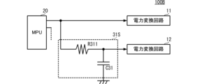
- FIG. 7 is a circuit block diagram showing an extended control circuit portion of the power supply system according to the third embodiment.
- FIG. 8 is a waveform diagram showing an example of a switching drive signal and a gate voltage signal.
- FIG. 8 shows the digital switching drive signal PWM11, the analog switching drive signal PWM12, the gate voltage signal V1H, and the gate voltage signal V2H in order from the top.
- the power supply system 100B according to the third embodiment differs from the power supply system 100 according to the first embodiment in the configuration of the extended control circuit.
- the rest of the configuration of the power supply system 100B is the same as that of the power supply system 100, and the description of the same portions will be omitted.
- the power supply system 100B includes an extended control circuit 31S.
- the power supply system 100B includes an extension control circuit 32S (not shown) having the same configuration as the extension control circuit 31S instead of the extension control circuit 32 of the power supply system 100.
- FIG. 1 is a diagrammatic representation of the power supply system 100B.
- the extended control circuit 31S differs from the extended control circuit 31 according to the first embodiment in that the resistor R312 and the diode D31 are eliminated. Other configurations of the extended control circuit 31S are the same as those of the extended control circuit 31 .
- a phase difference from the gate voltage signal V2H to the switching element Q2H of the circuit 12 can be set to a predetermined value (value other than 0).
- the power supply system 100B like the power supply system 100, has a simple configuration, suppresses a decrease in power conversion efficiency, and realizes multiphase driving according to the number of power conversion circuits to be driven.
- the power supply system 100B can realize a simpler circuit configuration than the power supply system 100.
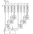
- FIG. 9 is a circuit block diagram showing an example of a power supply system according to the fourth embodiment.
- FIG. 10 is a waveform diagram showing an example of a switching drive signal and a gate voltage signal.
- FIG. 10 shows, in order from the top, a digital switching drive signal PWM11, an analog switching drive signal PWM12, a digital switching drive signal PWM12D, an analog switching drive signal PWM13, a digital switching drive signal PWM13D, a gate voltage signal V1H, a gate voltage signal V2H, and a gate voltage.
- Signal V3H is shown.
- a power supply system 100C according to the fourth embodiment differs from the power supply system 100A according to the second embodiment in that a plurality of extended control circuits are cascade-connected.
- the rest of the basic configuration of the power supply system 100C is the same as the basic circuit configuration of the power supply system 100A, and descriptions of similar parts will be omitted.
- the power supply system 100C is a system that multi-phase drives more than eight power conversion circuits.
- the power supply system 100C includes a plurality of power conversion circuits 11-18 and a plurality of extended control circuits 31L-36L.
- the plurality of power conversion circuits 11-18 have the same circuit configuration.
- a plurality of extended control circuits 31L-36L have the same circuit configuration.
- the plurality of extension control circuits 31L-36L have the same circuit configuration as the extension control circuit 31L shown in the second embodiment.
- the MPU 20 is connected to the power conversion circuit 11 and the power conversion circuit 15 by separate connection lines.
- the input terminal of the extended control circuit 31L is connected to the connection line between the MPU 20 and the power conversion circuit 11.
- An output end of the extended control circuit 31L is connected to the power conversion circuit 12 .
- the input terminal of the extended control circuit 32L is connected to the output terminal of the extended control circuit 31L.
- An output end of the extended control circuit 32L is connected to the power conversion circuit 13 .
- the input terminal of the extended control circuit 33L is connected to the output terminal of the extended control circuit 32L.
- An output end of the extended control circuit 33L is connected to the power conversion circuit 14 .
- the input end of the extended control circuit 34L is connected to the connection line between the MPU 20 and the power conversion circuit 15.
- An output end of the extended control circuit 34L is connected to the power conversion circuit 16 .
- the input terminal of the extended control circuit 35L is connected to the output terminal of the extended control circuit 34L.
- An output end of the extended control circuit 35L is connected to the power conversion circuit 17 .
- the input terminal of the extended control circuit 36L is connected to the output terminal of the extended control circuit 35L.
- An output end of the extended control circuit 36L is connected to the power conversion circuit 18 .
- the MPU 20 outputs (supplies) the digital switching drive signal PWM11 to the power conversion circuit 11 .
- the MPU 20 also outputs (supplies) a digital switching drive signal PWM15 to the power conversion circuit 15 .
- the digital switching drive signal PWM15 is a signal having a predetermined phase difference with respect to the digital switching drive signal PWM11.
- This phase difference refers to the number (number) of power conversion circuits that are multiphase-driven in the power supply system 100C, and is determined by the number (number) of power conversion circuits that the MPU 20 directly outputs the digital switching drive signal. For example, when 36 power conversion circuits are multi-phase driven and the number of power conversion circuits to which the MPU 20 directly outputs the digital switching drive signal is 4, the phase difference is set to 90°.
- the extended control circuit 31L receives the digital switching drive signal PWM11, generates an analog switching drive signal PWM12 as shown in FIG. 10, and generates a digital switching drive signal PWM12D from the analog switching drive signal PWM12.
- the extended control circuit 31L outputs a digital switching drive signal PWM12D to the power conversion circuit 12.
- the extended control circuit 32L receives the digital switching drive signal PWM12D, generates an analog switching drive signal PWM13, and generates a digital switching drive signal PWM13D from the analog switching drive signal PWM13, as shown in FIG.
- the extended control circuit 32L outputs the digital switching drive signal PWM13D to the power conversion circuit 13.
- the expansion control circuit 33L like the expansion control circuits 31L and 32L, receives the digital switching drive signal PWM13D and generates the digital switching drive signal PWM14D.
- the extended control circuit 33L outputs the digital switching drive signal PWM14D to the power conversion circuit 14.
- the digital switching drive signal PWM12D becomes a signal delayed by a predetermined phase difference with respect to the digital switching drive signal PWM11
- the digital switching drive signal PWM13D is a signal delayed by a predetermined phase difference with respect to the digital switching drive signal PWM12D
- the digital switching drive signal PWM14D becomes a signal delayed by a predetermined phase difference with respect to the digital switching drive signal PWM13D.
- the power supply system 100C can generate a plurality of sequentially delayed digital switching drive signals PWM12D, PWM13D, and PWM14D from one digital switching drive signal PWM11 and supply them to the plurality of power conversion circuits 11-14.
- the extended control circuit 34L receives the digital switching drive signal PWM15 as input, generates a digital switching drive signal PWM16D, and outputs it to the power conversion circuit 16.
- the extended control circuit 35L receives the digital switching drive signal PWM16D as an input, generates a digital switching drive signal PWM17D, and outputs it to the power conversion circuit 17 .
- the extended control circuit 36L receives the digital switching drive signal PWM17D as an input, generates a digital switching drive signal PWM18D, and outputs it to the power conversion circuit 18 .
- the power supply system 100C can generate a plurality of sequentially delayed digital switching drive signals PWM16D, PWM17D, and PWM18D from one digital switching drive signal PWM15, and supply them to a plurality of power conversion circuits 15-18.
- one digital switching drive signal output from the MPU 20 can be used to drive four or more power conversion circuits in multiphase.
- the power supply system 100C can achieve multiphase drive without unnecessarily increasing the number of MPUs 20 even in a configuration that requires more power conversion circuits.
- the power supply system 100C can configure a scale-expanded power supply system with a simple circuit configuration.
- the number of power conversion circuits to which the MPU 20 directly outputs a digital switching drive signal is four (for example, in FIG. 9,
- the phase difference between the digital switching drive signal PWM15 and the digital switching drive signal PWM19 (the drive signal to the power conversion circuit 191 not shown) is set to 72°, for example.
- the phase difference between the digital switching drive signal PWM19 (the drive signal to the power conversion circuit 191 not shown) and the digital switching drive signal PWM20 (the drive signal to the power conversion circuit 192 not shown) is, for example, , 18°. Furthermore, the phase difference between the digital switching drive signal PWM20 (the drive signal to the power conversion circuit 192 not shown) and the digital switching drive signal PWM11 is set to 18°, for example. As a result, when 20 power conversion circuits are used, the power supply balance is improved, and a decrease in power conversion efficiency can be further suppressed.
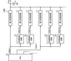
- FIG. 11 is a circuit block diagram showing an example of a power supply system according to the fifth embodiment.
- FIG. 12 is a waveform diagram showing an example of a switching drive signal and a gate voltage signal.
- FIG. 12 shows, in order from the top, a digital switching drive signal PWM11, an analog switching drive signal PWM12, a digital switching drive signal PWM12D, an analog switching drive signal PWM13, a digital switching drive signal PWM13D, a gate voltage signal V1H, a gate voltage signal V2H, and a gate voltage.
- Signal V3H is shown.
- a power supply system 100D according to the fifth embodiment differs from the power supply system 100A according to the second embodiment in that a plurality of extended control circuits are connected in parallel.
- the rest of the basic configuration of the power supply system 100D is the same as the basic circuit configuration of the power supply system 100A, and the description of the same portions will be omitted.
- the power supply system 100C is a system that multi-phase drives more than six power conversion circuits.
- the power supply system 100D includes a plurality of power conversion circuits 11-16 and a plurality of extended control circuits 31L-34L.
- the plurality of power conversion circuits 11-16 have the same circuit configuration.
- a plurality of extended control circuits 31L-34L have the same circuit configuration.
- the extended control circuits 31L to 34L have the same circuit configuration as the extended control circuit 31L shown in the second embodiment, but have different CR time constant settings.
- the MPU 20 is connected to the power conversion circuit 11 and the power conversion circuit 14 through individual connection lines.
- the input terminal of the extended control circuit 31L is connected to the connection line between the MPU 20 and the power conversion circuit 11.
- An output end of the extended control circuit 31L is connected to the power conversion circuit 12 .
- the input terminal of the extended control circuit 32L is connected to the connection line between the MPU 20 and the power conversion circuit 11.
- An output end of the extended control circuit 32L is connected to the power conversion circuit 13 .
- the input terminal of the extended control circuit 33L is connected to the connection line between the MPU 20 and the power conversion circuit 14.
- An output end of the extended control circuit 33L is connected to the power conversion circuit 15 .
- the input terminal of the extended control circuit 34L is connected to the connection line between the MPU 20 and the power conversion circuit 14.
- An output end of the extended control circuit 34L is connected to the power conversion circuit 16 .
- the MPU 20 outputs (supplies) the digital switching drive signal PWM11 to the power conversion circuit 11 .
- the MPU 20 also outputs (supplies) a digital switching drive signal PWM 14 to the power conversion circuit 14 .
- the digital switching drive signal PWM14 is a signal having a predetermined phase difference with respect to the digital switching drive signal PWM11. Note that the setting of the phase difference is performed on the same principle as in the above-described fourth embodiment, and the description thereof is omitted.
- the extended control circuit 31L receives the digital switching drive signal PWM11, generates an analog switching drive signal PWM12 as shown in FIG. 11, and generates a digital switching drive signal PWM12D from the analog switching drive signal PWM12.
- the extended control circuit 31L outputs a digital switching drive signal PWM12D to the power conversion circuit 12.
- the extended control circuit 32L receives the digital switching drive signal PWM11, generates an analog switching drive signal PWM13 as shown in FIG. 11, and generates a digital switching drive signal PWM13D from the analog switching drive signal PWM13.
- the extended control circuit 32L outputs the digital switching drive signal PWM13D to the power conversion circuit 13.
- the analog switching drive signal PWM13 has a waveform different from that of the analog switching drive signal PWM12. More specifically, the analog switching drive signal PWM13 reaches the on-voltage threshold THon later than the analog switching drive signal PWM12. Also, the analog switching drive signal PWM13 reaches the off-voltage threshold THoff later than the analog switching drive signal PWM12.
- the time difference between the time of the ON voltage threshold THon and the time of the OFF voltage threshold THoff in the analog switching drive signal PWM13 is equal to the time of the ON voltage threshold THon in the analog switching drive signal PWM12 and the OFF voltage threshold. It is set to be the same as the time difference from the time of THoff.
- the digital switching drive signal PWM12D becomes a signal delayed by a predetermined phase difference with respect to the digital switching drive signal PWM11
- the digital switching drive signal PWM13D is a signal delayed by a predetermined phase difference with respect to the digital switching drive signal PWM12D. becomes.
- the power supply system 100D can generate a plurality of sequentially delayed digital switching drive signals PWM12D and PWM13D from one digital switching drive signal PWM11 and supply them to the plurality of power conversion circuits 11-13.
- the extended control circuit 33L receives the digital switching drive signal PWM14 as input, generates a digital switching drive signal PWM15D, and outputs it to the power conversion circuit 15.
- the extended control circuit 34L receives the digital switching drive signal PWM15D as an input, generates a digital switching drive signal PWM16D, and outputs it to the power conversion circuit 16 .
- the power supply system 100D can generate a plurality of sequentially delayed digital switching drive signals PWM15D and PWM16D from one digital switching drive signal PWM14 and supply them to the plurality of power conversion circuits 14-16.
- one digital switching drive signal output from the MPU 20 can be used to multi-phase drive three or more power conversion circuits.
- the power supply system 100D can achieve multiphase drive without unnecessarily increasing the number of MPUs 20 even in a configuration that requires more power conversion circuits.
- the power supply system 100D can configure a scale-expanded power supply system with a simple circuit configuration.
- the power supply system 100D instead of the plurality of extended control circuits 31L-34L, a configuration similar to the extended control circuit 31 shown in the first embodiment can be adopted. In other words, a configuration that does not use the logic circuit 310 can also be applied to the power supply system 100D. Thereby, the power supply system 100D can realize a simpler circuit configuration.
- the on-time width of the switching drive signal output by the extended control circuit is set equal to the on-time width of the digital switching drive signal output by the MPU 20 .
- this is a value set by, for example, the number of power conversion circuits that are multiphase driven.
- the MPU 20 can adjust the on-time width based on the feedback voltage of the output voltage Vout and the feedback currents from the plurality of power conversion circuits 11-14. is.
- the on-time width of the digital switching drive signal output from the MPU 20 the on-voltage thresholds set in the extended control circuits 31 and 32
- the MPU 20 has an input terminal for PMBus signals, and can determine the number of power conversion circuits to be multiphase-driven according to the voltage and current specified by the PMBus signals to set the on-time width. can.
- 100, 100A, 100B, 100C, 100D power supply systems 110, 120, 130, 140: driving units 11-18, 191, 192: power conversion circuits 20, 20A, 20B: MPU 31, 31L, 31S, 32, 32L, 32S, 33L, 34L, 35L, 36L: extended control circuit 310: logic circuit C31: capacitors Ci1, Ci2, Ci3, Ci4: input capacitor Co: output capacitor D31: diodes L1, L2 , L3, L4: inductor Pin: common input terminal Pout: common output terminal Q1H, Q2H, Q3H, Q4H: switching elements Q1L, Q2L, Q3L, Q4L: switching elements R311, R312: resistor Ro: load
Landscapes
- Engineering & Computer Science (AREA)
- Power Engineering (AREA)
- Dc-Dc Converters (AREA)
Priority Applications (2)
| Application Number | Priority Date | Filing Date | Title |
|---|---|---|---|
| JP2023543794A JP7658444B2 (ja) | 2021-08-23 | 2022-08-08 | 規模拡張型スケーラブル電源システム |
| US18/583,563 US12531486B2 (en) | 2021-08-23 | 2024-02-21 | Scalable power supply system |
Applications Claiming Priority (2)
| Application Number | Priority Date | Filing Date | Title |
|---|---|---|---|
| JP2021-135279 | 2021-08-23 | ||
| JP2021135279 | 2021-08-23 |
Related Child Applications (1)
| Application Number | Title | Priority Date | Filing Date |
|---|---|---|---|
| US18/583,563 Continuation US12531486B2 (en) | 2021-08-23 | 2024-02-21 | Scalable power supply system |
Publications (1)
| Publication Number | Publication Date |
|---|---|
| WO2023026834A1 true WO2023026834A1 (ja) | 2023-03-02 |
Family
ID=85323090
Family Applications (1)
| Application Number | Title | Priority Date | Filing Date |
|---|---|---|---|
| PCT/JP2022/030208 Ceased WO2023026834A1 (ja) | 2021-08-23 | 2022-08-08 | 規模拡張型スケーラブル電源システム |
Country Status (3)
| Country | Link |
|---|---|
| US (1) | US12531486B2 (https=) |
| JP (1) | JP7658444B2 (https=) |
| WO (1) | WO2023026834A1 (https=) |
Families Citing this family (1)
| Publication number | Priority date | Publication date | Assignee | Title |
|---|---|---|---|---|
| WO2023182052A1 (ja) * | 2022-03-24 | 2023-09-28 | 株式会社村田製作所 | 規模拡張型スケーラブル電源システム |
Citations (5)
| Publication number | Priority date | Publication date | Assignee | Title |
|---|---|---|---|---|
| JPS50152650A (https=) * | 1974-05-28 | 1975-12-08 | ||
| JPS5571319A (en) * | 1978-11-24 | 1980-05-29 | Oki Electric Ind Co Ltd | Comparator circuit system |
| JPH02192371A (ja) * | 1989-01-20 | 1990-07-30 | Fuji Photo Film Co Ltd | 電荷結合型固体撮像装置 |
| JP2015146711A (ja) * | 2014-02-04 | 2015-08-13 | リコー電子デバイス株式会社 | マルチフェーズ型dc/dcコンバータ |
| JP2017158373A (ja) * | 2016-03-03 | 2017-09-07 | トヨタ自動車株式会社 | 多相昇圧コンバータの制御方法及び多相昇圧コンバータ |
Family Cites Families (32)
| Publication number | Priority date | Publication date | Assignee | Title |
|---|---|---|---|---|
| JPH05206802A (ja) * | 1992-01-28 | 1993-08-13 | Olympus Optical Co Ltd | 遅延回路 |
| US6246222B1 (en) * | 2000-08-30 | 2001-06-12 | National Semiconductor Corporation | Switching DC-to-DC converter and conversion method with rotation of control signal channels relative to paralleled power channels |
| US6574124B2 (en) * | 2001-09-13 | 2003-06-03 | Netpower Technologies, Inc. | Plural power converters with individual conditioned error signals shared on a current sharing bus |
| US6894466B2 (en) * | 2003-02-28 | 2005-05-17 | Astec International Limited | Active current sharing circuit |
| JP4480341B2 (ja) * | 2003-04-10 | 2010-06-16 | 日立プラズマディスプレイ株式会社 | プラズマディスプレイ装置 |
| WO2007148354A1 (en) * | 2006-06-21 | 2007-12-27 | Stmicroelectronics S.R.L. | Control device of a plurality of switching converters |
| JP4229177B2 (ja) * | 2006-11-30 | 2009-02-25 | ミツミ電機株式会社 | マルチフェーズdc−dcコンバータ |
| US8120203B2 (en) * | 2008-07-18 | 2012-02-21 | Intersil Americas Inc. | Intelligent management of current sharing group |
| JP2010119177A (ja) | 2008-11-12 | 2010-05-27 | Rohm Co Ltd | マルチフェーズ型dc/dcコンバータ |
| JP5690545B2 (ja) * | 2010-10-06 | 2015-03-25 | ルネサスエレクトロニクス株式会社 | 電源装置 |
| JP5842465B2 (ja) * | 2011-08-29 | 2016-01-13 | 株式会社リコー | 電源装置 |
| JP6034132B2 (ja) | 2012-10-24 | 2016-11-30 | 株式会社ソニー・インタラクティブエンタテインメント | Dc/dcコンバータおよびそれを用いたゲーム機器 |
| JP5600362B2 (ja) | 2013-02-18 | 2014-10-01 | ルネサスエレクトロニクス株式会社 | 電源用半導体装置 |
| US9748846B2 (en) * | 2013-10-28 | 2017-08-29 | Intersil Americas LLC | Power supply with droop control feedback for enhanced phase current sharing |
| JP6244987B2 (ja) * | 2014-03-05 | 2017-12-13 | 株式会社デンソー | 電源システム |
| US10381918B1 (en) * | 2018-02-19 | 2019-08-13 | Microchip Technology Incorporated | Multi-phase parallelable constant on time buck controller with phase interleaving ensured by ripple injection |
| JP6998252B2 (ja) | 2018-03-28 | 2022-01-18 | 株式会社Gsユアサ インフラシステムズ | スイッチング電源装置 |
| WO2020183823A1 (ja) * | 2019-03-14 | 2020-09-17 | 株式会社村田製作所 | システム電源装置 |
| WO2020183820A1 (ja) * | 2019-03-14 | 2020-09-17 | 株式会社村田製作所 | システムスイッチング電源装置 |
| JP7388436B2 (ja) * | 2019-07-09 | 2023-11-29 | 株式会社村田製作所 | 電源システム |
| US11469661B2 (en) * | 2019-10-25 | 2022-10-11 | Cirrus Logic, Inc. | Multiphase inductive boost converter with multiple operational phases |
| WO2021192377A1 (ja) * | 2020-03-26 | 2021-09-30 | 株式会社村田製作所 | マルチコンバータ電源システム |
| JP7298774B2 (ja) * | 2020-03-26 | 2023-06-27 | 株式会社村田製作所 | マルチコンバータ電源システム |
| JP7386431B2 (ja) * | 2020-03-30 | 2023-11-27 | パナソニックIpマネジメント株式会社 | スイッチング装置、スイッチング電源装置、及び車両 |
| JP7445541B2 (ja) * | 2020-06-25 | 2024-03-07 | ローム株式会社 | 半導体装置及び降圧型マルチフェーズdc/dcコンバータ |
| JP7485095B2 (ja) * | 2021-01-19 | 2024-05-16 | 株式会社村田製作所 | 電源システム装置 |
| JP7485094B2 (ja) * | 2021-01-19 | 2024-05-16 | 株式会社村田製作所 | 電源システム装置 |
| CN115622401B (zh) * | 2021-07-16 | 2024-08-30 | 圣邦微电子(北京)股份有限公司 | 多相功率转换电路的控制电路和多相电源 |
| US11545903B1 (en) * | 2021-12-03 | 2023-01-03 | Monolithic Power Systems, Inc. | Controller for driving a power switch in slave phase of a multiphase power converter and power converter comprising the same |
| US12199517B2 (en) * | 2022-03-21 | 2025-01-14 | Monolithic Power Systems, Inc. | Controller for driving a power switch in slave phase of a multiphase power converter and power converter comprising the same |
| CN115250055B (zh) * | 2022-05-09 | 2025-11-11 | 杰华特微电子股份有限公司 | 多相电源的控制电路、控制方法及多相电源 |
| CN221575141U (zh) * | 2023-11-29 | 2024-08-20 | 安克创新科技股份有限公司 | 开关器件的驱动电路、开关电源 |
-
2022
- 2022-08-08 WO PCT/JP2022/030208 patent/WO2023026834A1/ja not_active Ceased
- 2022-08-08 JP JP2023543794A patent/JP7658444B2/ja active Active
-
2024
- 2024-02-21 US US18/583,563 patent/US12531486B2/en active Active
Patent Citations (5)
| Publication number | Priority date | Publication date | Assignee | Title |
|---|---|---|---|---|
| JPS50152650A (https=) * | 1974-05-28 | 1975-12-08 | ||
| JPS5571319A (en) * | 1978-11-24 | 1980-05-29 | Oki Electric Ind Co Ltd | Comparator circuit system |
| JPH02192371A (ja) * | 1989-01-20 | 1990-07-30 | Fuji Photo Film Co Ltd | 電荷結合型固体撮像装置 |
| JP2015146711A (ja) * | 2014-02-04 | 2015-08-13 | リコー電子デバイス株式会社 | マルチフェーズ型dc/dcコンバータ |
| JP2017158373A (ja) * | 2016-03-03 | 2017-09-07 | トヨタ自動車株式会社 | 多相昇圧コンバータの制御方法及び多相昇圧コンバータ |
Also Published As
| Publication number | Publication date |
|---|---|
| JP7658444B2 (ja) | 2025-04-08 |
| JPWO2023026834A1 (https=) | 2023-03-02 |
| US12531486B2 (en) | 2026-01-20 |
| US20240195282A1 (en) | 2024-06-13 |
Similar Documents
| Publication | Publication Date | Title |
|---|---|---|
| US7521913B2 (en) | Active transient response circuits, system and method for digital multiphase pulse width modulated regulators | |
| EP1691473B1 (en) | PWM controller with dual-edge modulation using dual ramps for fast response | |
| US7208921B2 (en) | DC-DC regulator with switching frequency responsive to load | |
| US8193796B2 (en) | Multiphase power regulator with load adaptive phase control | |
| US7492134B2 (en) | Multiphase power regulator with load adaptive phase control | |
| US8466665B1 (en) | Adaptive digital pulse width modulation generator for buck converters | |
| CN101911457B (zh) | 具有与占空比无关的电流限制的电源调节器系统及其调节方法 | |
| US8400131B2 (en) | Voltage converter and LED driver circuits with progressive boost, skip, and linear mode operation | |
| US8829872B1 (en) | Systems and methods for dropping and/or adding phases in multiphase regulators | |
| US20070139973A1 (en) | MCU/driver point of load digital controller with optimized voltage | |
| TWI524617B (zh) | 電源供應系統、包含其之積體電路及用以控制其之方法 | |
| US20080106917A1 (en) | Variable edge modulation in a switching regulator | |
| US9793683B2 (en) | Digital pulse width modulation power supply with pico second resolution | |
| US20130099834A1 (en) | Ramp signal generation circuit and ramp signal adjustment circuit | |
| CN113541485A (zh) | 多相功率转换器的电流共享 | |
| US9431900B2 (en) | Dynamic operating frequency control of a buck power converter having a variable voltage output | |
| CN107112893A (zh) | 功率转换装置 | |
| US10992230B1 (en) | Multi-phase switching mode power supply with adaptive synchronous drivers | |
| JP7658444B2 (ja) | 規模拡張型スケーラブル電源システム | |
| JP6794240B2 (ja) | 昇降圧dc/dcコンバータ | |
| CN115566881B (zh) | 多相dc-dc变换器的控制电路、控制方法和开关电源 | |
| US9071138B2 (en) | Adaptive digital pulse width modulation generator for buck converters | |
| JP7775990B2 (ja) | 規模拡張型スケーラブル電源システム | |
| WO2020146970A1 (en) | Power converter with multi-mode timing control | |
| US20250373163A1 (en) | Ramp signal sorting in multiphase power converters |
Legal Events
| Date | Code | Title | Description |
|---|---|---|---|
| 121 | Ep: the epo has been informed by wipo that ep was designated in this application |
Ref document number: 22861124 Country of ref document: EP Kind code of ref document: A1 |
|
| WWE | Wipo information: entry into national phase |
Ref document number: 2023543794 Country of ref document: JP |
|
| NENP | Non-entry into the national phase |
Ref country code: DE |
|
| 122 | Ep: pct application non-entry in european phase |
Ref document number: 22861124 Country of ref document: EP Kind code of ref document: A1 |