WO2023026432A1 - 回転力を伝達するロボットの動力伝達機構およびロボットの駆動装置 - Google Patents
回転力を伝達するロボットの動力伝達機構およびロボットの駆動装置 Download PDFInfo
- Publication number
- WO2023026432A1 WO2023026432A1 PCT/JP2021/031368 JP2021031368W WO2023026432A1 WO 2023026432 A1 WO2023026432 A1 WO 2023026432A1 JP 2021031368 W JP2021031368 W JP 2021031368W WO 2023026432 A1 WO2023026432 A1 WO 2023026432A1
- Authority
- WO
- WIPO (PCT)
- Prior art keywords
- power transmission
- transmission mechanism
- rotating member
- shaft
- base material
- Prior art date
- Legal status (The legal status is an assumption and is not a legal conclusion. Google has not performed a legal analysis and makes no representation as to the accuracy of the status listed.)
- Ceased
Links
Images


Classifications
-
- B—PERFORMING OPERATIONS; TRANSPORTING
- B25—HAND TOOLS; PORTABLE POWER-DRIVEN TOOLS; MANIPULATORS
- B25J—MANIPULATORS; CHAMBERS PROVIDED WITH MANIPULATION DEVICES
- B25J17/00—Joints
Definitions
- the present invention relates to a robot power transmission mechanism and a robot driving device that transmit rotational force.
- the robot can change the position and posture of the work tool by driving its constituent members such as arms.
- a drive system including an electric motor is arranged on the robot to move the component.
- a drive may be arranged at the joint to move the component.
- the drive includes a power transmission mechanism for transmitting rotational force from one member to another member.
- a power transmission mechanism that transmits torque from the output shaft of the electric motor to the input of the speed reducer.
- a method for transmitting the rotational force of the shaft to another member for example, there is a method of forming a female thread on the end face of the shaft and fixing the other member with a bolt.
- a method of fixing another member by shrink fitting at the end of the shaft In this method, another member is placed at the end of the shaft when heated and expanded. The other member is then fixed to the shaft by cooling and shrinking the other member.
- spline connection or key connection may be used in order to reliably transmit the rotational force of the shaft.
- the inside of the drive includes parts whose performance deteriorates or deteriorates over time as the drive is driven. It is preferable that such parts have a structure in which they can be replaced when deteriorated. For example, it is preferable to replace the speed reducer every predetermined operating period.
- a mechanism in which the end of the shaft and another member are splined or keyed can make the diameter of the shaft smaller than a mechanism in which another member is fixed to the end face of the shaft with a bolt. As a result, an increase in size of the device can be suppressed.
- the shaft is cylindrical (hollow shaft)
- the spline connection or key connection cannot be performed due to the thinness of the shaft.
- spline coupling causes backlash in the rotational direction.
- key coupling a method of fixing the shaft and other members with bolts or set screws is common.
- key coupling there is a problem that it is difficult to completely avoid backlash in the rotational direction.
- the spline connection cannot prevent movement of other members in the direction in which the rotation axis extends.
- a load is generated in the direction of the rotation axis while the input section is rotating.
- a problem with the spline connection is that it is difficult to prevent movement in the rotational axis direction (one direction parallel to the rotational axis and the direction opposite to the one direction) when this load is applied.
- the shaft and other members can be fixed to each other by arranging an adhesive on the spline joint portion or the key joint portion.
- an adhesive on the spline joint portion or the key joint portion.
- a power transmission mechanism for a robot includes a base material having a recess extending along the rotation axis of the first rotating member and having a hole through which the first rotating member is inserted.
- the power transmission mechanism is provided with a ring member disposed in the recess and having a substantially wedge-shaped cross-section when cut along a plane perpendicular to the circumferential direction.
- the power transmission mechanism has a hole through which the first rotating member is inserted, and includes a pressure flange having a tip portion for pressing the ring member.
- the power transmission mechanism includes a fastening member for applying force to the substrate and the pressure flange in a direction that the substrate and the pressure flange approach each other.
- the substrate has a mounting portion that secures the second rotating member.
- the ring member is fixed to the first rotating member by being pressed in the direction of the rotating shaft at its distal end to generate a force to reduce the diameter.
- the substrate and pressure flange are fixed relative to the ring member. The rotational force of one of the first rotating member and the second rotating member is transmitted to the other rotating member via the base material.
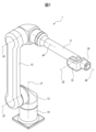
- FIG. 1 is a perspective view of a robot in an embodiment;
- FIG. 1 is a cross-sectional view of a first driving device including a first power transmission mechanism in an embodiment;
- FIG. 4 is an enlarged sectional view of the first power transmission mechanism;
- FIG. 4 is an enlarged cross-sectional view of a power transmission mechanism of a first comparative example;
- FIG. 6 is a schematic partial cross-sectional view of a power transmission mechanism of a second comparative example;
- 4 is an enlarged cross-sectional view of the first power transmission mechanism including another base material in the embodiment;
- FIG. FIG. 10 is an enlarged perspective view of a protruding portion of another base material in the embodiment; It is a sectional view of the 2nd drive including the 2nd power transmission mechanism in an embodiment.
- 4 is an enlarged cross-sectional view of a second power transmission mechanism;
- FIG. 8 is an enlarged cross-sectional view of a third power transmission mechanism;
- FIG. A power transmission mechanism for a robot and a drive device for a robot including the power transmission mechanism according to an embodiment will be described with reference to FIGS. 1 to 10.
- FIG. A power transmission mechanism transmits rotational force from one rotating member to another rotating member.
- FIG. 1 is a perspective view of the robot according to this embodiment.
- the robot 1 of this embodiment is an articulated robot including a plurality of joints.
- the robot 1 includes a plurality of rotatable components. Each component is formed to rotate around drive shafts J1 to J6.
- the power transmission mechanism of this embodiment is arranged at the joint of the robot in order to drive the constituent members of the robot.
- the robot 1 includes a base portion 14 fixed to an installation surface and a swivel base 13 supported by the base portion 14 .
- the swivel base 13 rotates around the drive axis J1 with respect to the base portion 14 .
- the robot 1 includes a forearm arm 11 and an upper arm 12 .
- Upper arm 12 is supported by swivel base 13 .
- the upper arm 12 rotates about the drive axis J2 with respect to the swivel base 13 .
- the forearm arm 11 is supported by the upper arm 12 .
- the forearm arm 11 rotates relative to the upper arm 12 around the drive axis J3. Further, the forearm arm 11 rotates around the drive axis J4.
- Robot 1 includes a wrist 15 supported by forearm arm 11 .
- the wrist 15 rotates around the drive axis J5.
- Wrist 15 also includes a flange 16 that rotates about drive axis J6.
- a work tool is fixed to the
- the robot 1 of this embodiment includes a base portion 14, a swivel base 13, an upper arm 12, a forearm arm 11, and a wrist 15 as constituent members.
- the robot of this embodiment has six drive shafts, it is not limited to this form. A robot that changes its position and orientation with any mechanism can be employed.
- FIG. 2 shows a cross-sectional view of the first driving device in this embodiment. 1 and 2, the first drive device 2 is a device for rotating the forearm arm 11 around the drive axis J4.
- the driving device 2 is arranged, for example, at the end of the forearm arm 11 opposite to the side where the wrist 15 is arranged so that the direction indicated by the arrow 131 is the direction where the wrist 15 is arranged.
- the first driving device 2 includes an electric motor 45 including a rotor 45a and a stator 45b.
- the rotor 45 a is fixed to the shaft 21 .
- Shaft 21 functions as an output shaft of electric motor 45 .
- the shaft 21 is formed elongated.
- the shaft 21 of this embodiment is a cylindrical member having a hollow hole. The shaft 21 rotates about the drive shaft J4 as a rotation axis.
- the rotational force of the shaft 21 is transmitted to the flange 25 via the reduction gear 31.
- the flanges 25 and 26 are fixed to each other with bolts 56 .
- the flanges 26 and 27 are fixed to each other with bolts 57 .
- the flanges 25, 26, 27 rotate together.
- the drive device 2 includes a housing 22 in which an electric motor 45 is arranged.
- the shaft 21 is rotatably supported by bearings 51 and 52 .
- the bearing 51 is fixed by the housing 22 .
- the driving device 2 includes a housing 23 in which an electromagnetic brake 46 is arranged, and a housing 24 in which an encoder 47 as a rotational position detector is arranged.
- Electromagnetic brake 46 brakes shaft 21 .
- Encoder 47 detects the rotational position of electric motor 45 .
- the housing 22, housing 23, and housing 24 are fixed to each other by fastening members such as bolts.
- a bearing fixing member 28 for fixing the bearing 52 is arranged between the housing 22 and the housing 23 .
- the bearing fixing member 28 is fixed to the housing 23 with a fastening member such as a bolt. By removing the fastening member, the housings 24 , 23 , 22 and the bearing fixing member 28 can be removed from the side opposite to the arrow 131 .
- a protective tube 66 made of resin is arranged inside the shaft 21 .
- the protective tube 66 is cylindrically formed along the inner surface of the shaft 21 .
- a wire such as an electric wire, an air tube, or an optical communication cable is inserted through the protective tube 66 .
- the protective tube 66 is fixed by sandwiching the sandwiching portion 66 a between the flanges 26 and 27 . By arranging the protective tube 66 , the striatum can be arranged inside the joint of the robot 1 .
- FIG. 3 shows an enlarged cross-sectional view of the first power transmission mechanism of the first drive device in this embodiment. 2 and 3, the first power transmission mechanism 5 includes a fixing device 32. As shown in FIG. The first power transmission mechanism 5 transmits the rotational force of the shaft 21 output by the electric motor 45 to the speed reducer 31 .
- the reduction gear 31 of the first driving device 2 is a strain wave gearing.
- the speed reducer 31 has a wave generator 31a.
- the wave generator 31a is also called a wave generator.
- the wave generator 31a includes a cam having an elliptical shape when viewed from the direction of the rotation axis and a ball bearing arranged on the outer peripheral surface of the cam.
- the inner ring of the ball bearing is fixed to an elliptical cam.
- the outer race of the ball bearing is formed so as to be elastically deformed via a plurality of balls.
- the cam of the wave generating section 31a functions as the input section of the speed reducer 31.
- the speed reducer 31 has an elastic cylindrical member 31b that is elastically deformable.
- the elastic tubular member 31b is an external gear and is also called a flexspline.
- the elastic tubular member 31b is formed to deform as the cam rotates.
- the elastic cylindrical member 31b has teeth 31bb formed on the outer peripheral surface.
- the elastic cylindrical member 31b is fixed to the housing 22 with bolts 55. As shown in FIG. While the wave generator 31a rotates, the elastic cylindrical member 31b is fixed so as not to rotate.
- the speed reducer 31 has an annular member 31c.
- the annular member 31c is an internal gear and is also called a circular spline.
- a tooth portion that engages with the tooth portion 31bb of the elastic cylindrical member 31b is formed on the inner surface of the annular member 31c.
- the number of teeth of the elastic tubular member 31b is smaller than the number of teeth of the annular member 31c. Therefore, when the wave generating portion 31a makes one rotation, the annular member 31c rotates at a rotation speed of less than one rotation according to the difference in the number of teeth of the tooth portion.
- the annular member 31c functions as an output portion of the speed reducer 31.
- the reduction gear 31 can reduce the speed at a reduction ratio corresponding to the difference between the number of teeth of the elastic cylindrical member 31b and the number of teeth of the annular member 31c.
- An annular member 31 c as an output portion of the speed reducer 31 is fixed to the flange 25 with bolts 39 .
- the rotational force of the annular member 31c is transmitted to the flange 27 via the flanges 25,26.
- the flange 27 is fixed, for example, to the housing of the forearm arm 11 . Rotation of flange 27 relative to housings 22, 23, 24 causes forearm arm 11 to rotate about drive axis J4.
- the first power transmission mechanism 5 transmits the rotational force of the shaft 21 to the cam of the wave generating section 31a as the input section of the speed reducer 31.
- the shaft 21 corresponds to the first rotating member
- the cam of the wave generating section 31a of the speed reducer 31 corresponds to the second rotating member.
- a fixing device 32 of the power transmission mechanism 5 fixes the wave generating portion 31 a to the shaft 21 .
- the fixing device 32 includes a base material 33 having a hole through which the shaft 21 is inserted.
- the base material 33 has a shape surrounding the shaft 21 .
- Base material 33 in the present embodiment is formed in a cylindrical shape.
- the base material 33 has a recessed portion 33 a extending along the rotation axis of the shaft 21 .
- the recessed portion 33 a is formed on the inner surface of the base material 33 .
- the fixing device 32 has ring members 35 and 36 arranged in the recessed portion 33 a of the base material 33 .
- Each of the ring members 35 and 36 is formed to have a wedge-shaped cross-section when cut along a plane perpendicular to the circumferential direction.
- the ring members 35 and 36 are formed to have a triangular cross-sectional shape.
- Each of the ring members 35 and 36 is formed such that the surface extending in the circumferential direction is a conical surface.
- the conical surface of the ring member 35 and the conical surface of the ring member 36 are arranged so as to contact each other.
- the fixing device 32 includes a pressing flange 34 having a hole through which the shaft 21 is inserted.
- the pressing flange 34 has a shape surrounding the shaft 21 .
- the pressing flange 34 is formed to have an L-shaped cross section when cut along a plane perpendicular to the circumferential direction.
- the pressing flange 34 has a tip portion 34 a that presses the ring member 36 .
- tip portion 34a has a shape corresponding to depression portion 33a.
- the tip portion 34a is formed so as to fit into the recessed portion 33a.
- the fixing device 32 includes a bolt 37 as a fastening member for applying force to the base material 33 and the pressing flange 34 so that the base material 33 and the pressing flange 34 approach each other.
- a bolt 37 as a fastening member for applying force to the base material 33 and the pressing flange 34 so that the base material 33 and the pressing flange 34 approach each other.
- a gap is formed between the standing portion of the base material 33 and the standing portion of the pressing flange 34 in the cross-sectional shape.
- a radial force acts on the ring members 35 and 36 due to the action of the conical surfaces of the ring members 35 and 36 .
- a radially inward force that is, a diameter-contracting force acts on the ring member 36 .
- a radially outward force acts on the ring member 35 , that is, a radially expanding force.
- the ring member 36 crimps the shaft 21 , and the ring member 35 , the base material 33 , and the pressing flange 34 are fixed to the ring member 36 . As a result, the base material 33 and the pressing flange 34 are fixed to the shaft 21 .
- base material 33 of the present embodiment has screw hole 33b as a mounting portion for fixing wave generating portion 31a.
- the cam of the wave motion generating portion 31a is fixed to the base material 33 by a bolt 38 as a fastening member. Therefore, the wave generator 31a rotates integrally with the fixing device 32. As shown in FIG. Thus, the rotational force of the first rotating member is transmitted to the second rotating member via the base material 33 of the fixing device 32 .
- a main bearing 41 is arranged on the side of the annular member 31c.
- the main bearing 41 of this embodiment is a cross roller bearing.
- the main bearing 41 has an inner ring 41a and an outer ring 41b.
- the outer ring 41b is fixed to the housing 22 by bolts 55 together with the elastic tubular member 31b.
- the outer ring 41 b is a member that does not rotate with respect to the housing 22 .
- the inner ring 41a is fixed by bolts 39 to the flange 25 and the annular member 31c. For this reason, the inner ring 41a, the annular member 31c, the flanges 25, 26, 27, and the protective tube 66 rotate integrally.
- Oil seals 61 and 62 are arranged on the outer peripheral surface of the shaft 21 to prevent internal lubricating oil from leaking to the outside and to prevent foreign matter from entering from the outside. Further, an oil seal 63 is arranged to prevent the lubricating oil inside the main bearing 41 from leaking to the outside and to prevent foreign matter from entering from the outside.
- the speed reducer 31 which is a wave gear device, has a limited life. In order to replace the speed reducer 31, it is necessary to pull out the wave generator 31a in the direction of the arrow 131. As shown in FIG. If it is pulled out in the direction opposite to the arrow 131, the wave generating portion 31a and the elastic cylindrical member 31b will be damaged.
- the flange 27 can be removed from the flange 26 by removing the bolt 57. Also, the fixing of the protective tube 66 is released, and the protective tube 66 can be taken out in the direction indicated by the arrow 131 . Flange 26 can then be removed from flange 25 by removing bolts 56 . Flange 25 can then be removed by removing bolts 39 . By removing the bolt 38, the wave generating portion 31a can be removed.
- the housings 23 and 24 can be removed from the housing 22 by removing fastening members (not shown). Then, the encoder 47 and the electromagnetic brake 46 can be taken out in the direction opposite to the arrow 131 . Further, the bearing fixing member 28 and the bearing 52 can be removed by removing the fastening member (not shown). The shaft 21 can then be withdrawn in the direction opposite to the arrow 131 together with the rotor 45a. Then, the bearing 51 can be taken out.
- the drive device 2 can be disassembled and the speed reducer 31 can be replaced. Furthermore, replacement of bearings 51, 52 and oil seals 61, 62, 63 is also possible.
- the driving device 2 it can be assembled in the reverse order of the disassembling procedure. As described above, the drive device 2 in the present embodiment can be easily disassembled by removing the fastening member, and the parts can be replaced.
- FIG. 4 shows an enlarged sectional view of the power transmission mechanism of the first comparative example.
- the wave motion generator 31 a of the speed reducer 31 is fixed to the shaft 71 with bolts 72 . That is, reduction gear 31 is directly fixed to shaft 71 without via fixing device 32 including base material 33 and pressing flange 34 in the present embodiment.
- the bolt 72 is fixed to the end surface of the shaft 71 .
- the outer diameter of the shaft 71 is increased because a threaded hole for the bolt 72 is required. For this reason, the inner diameters of the oil seal 63, the bearing 51, etc. become large. As a result, there is a problem that the driving device becomes large.
- Fig. 5 shows a schematic cross-sectional view of a power transmission mechanism of a second comparative example.
- a plurality of shafts are coaxially arranged.
- Shaft 73 is connected to shaft 74 .
- Shaft 76 is connected to shaft 77 .
- the shafts 73 and 74 are rod-shaped shafts without hollow holes.
- Shafts 76 and 77 are cylindrical shafts.
- Shaft 73 is fixed to shaft 74 by arranging bolts 75 on the flange portion of shaft 73 .
- the shaft 76 is fixed to the shaft 77 by arranging a bolt 78 on the flange portion of the shaft 76 .
- the power transmission mechanism 5 of this embodiment is small and can be easily disassembled.
- the power transmission mechanism 5 is fixed by a fixing device including a ring member having a substantially wedge-shaped cross-section when cut along a plane perpendicular to the circumferential direction, backlash and other looseness do not occur.
- this force can be received by the fixing device 32 . That is, it is possible to suppress the movement of the input portion of the speed reducer 31 in the axial direction.
- the ring members 35, 36 of the fixing device 32 in this embodiment each have a conical surface.
- the conical surfaces come into contact with each other. It is possible to efficiently convert the pressing force in the direction of the rotation axis by the distal end portion 34a into a radial contraction force.
- the surface with which the ring member contacts is not limited to the conical surface, and the cross-sectional shape when cut along a plane perpendicular to the circumferential direction may be formed in a curved shape.
- bolts 37 are employed as fastening members that move the base material 33 and the pressing flange 34 toward each other to bias the base material 33 and the pressing flange 34 .
- this configuration it is possible to apply a force to the base material 33 and the pressing flange 34 in a direction of approaching each other with a strong force of the bolt axial force.
- the bolt 37 it can be easily removed.
- the first rotating member in this embodiment is the output shaft of the electric motor 45 .
- the first rotating member is not limited to this form, and any rotating member can be adopted.
- the first rotating member may be part of a speed reducer.
- the shaft 21 in this embodiment is a cylindrical member having a hollow hole.
- the thickness of the shaft can be reduced.
- the diameter of the hollow hole inside the shaft can be increased.
- a filamentous body such as an air pipe or an electric wire may be passed through the interior of the joint.
- the space inside the protective tube can be increased, and many filaments can be passed through it.
- shaft 21 of the present embodiment has stepped portion 21a and stepped portion 21b as movement restricting portions that restrict movement of shaft 21 in the direction of the rotation axis.
- Bearings 51 and 52 are engaged with the stepped portion 21a and the stepped portion 21b.
- the bearing 51 is fixed by the housing 22
- the bearing 52 is fixed by the bearing fixing member 28 .
- the movement restricting portion that restricts the movement of the shaft 21 in the direction of the rotation axis
- the movement of the shaft 21 in the axial direction is suppressed.
- the devices arranged around the shaft 21 are stably driven. For example, it is possible to suppress the axial movement of the wave generating portion 31a of the speed reducer 31 and perform stable deceleration.
- encoder 47 may comprise a disk with a slit through which light passes.
- the disc is fixed to the shaft 21 .
- the base material 33 and the second rotating member of the fixing device 32 of this embodiment can be integrally formed.
- the base material 33 and the frame of the wave generating section 31a can be integrally formed.
- the base material 33 is deformed, and the deformation is propagated to the wave generating portion 31a, which may cause the reduction gear 31 to malfunction.
- the base member of the fixing device and the second rotating member are separate members, and that the deformation is less likely to propagate, as in the present embodiment.
- FIG. 6 shows an enlarged cross-sectional view showing a modification of the base material of the fixing device of the present embodiment.
- FIG. 7 shows an enlarged perspective view of the portion of the substrate where the screw holes are formed.
- the modified base material 40 has recesses 40a and screw holes 40b, like the base material 33 described above.
- the substrate 40 has a protruding portion 40c formed in the area where the screw hole 40b is formed.
- the projecting portion 40 c is a portion that projects from the surface of the base material 40 .
- the projecting portion 40c is formed around the threaded hole 40b of the bolt 38.
- the protrusion 40c has the shape of a truncated cone.
- the substrate 40 is in contact with the wave generating portion 31a of the speed reducer 31 at the top surface of the projecting portion 40c.
- the base material 40 When tightening the bolt 37 that biases the base material 40 and the pressing flange 34 in a direction to bring them closer together, the base material 40 may be deformed. If the substrate and the wave generating portion are in contact with each other over a large area, a large amount of deformation of the substrate may be propagated, and the wave generating portion 31a may be easily deformed. As a result, there is a possibility that the meshing of the gear teeth of the speed reducer may be defective. In addition, abnormal noise is generated and the teeth are worn out early. Like the base material 40 of the modified example, the projecting portion 40c is provided so that only the peripheral portion where the bolts 38 are arranged contacts the wave generating portion 31a, and other portions do not contact the wave generating portion 31a. Therefore, the amount of deformation of the base material 40 propagated to the wave generating portion 31a can be minimized.
- first drive device including the first power transmission mechanism of the present embodiment is arranged at the portion that rotates the forearm arm around the drive shaft J4, it is not limited to this form.
- a device similar to the first driving device can be applied to other joints.
- FIG. 8 shows a cross-sectional view of a second driving device having a second power transmission mechanism according to this embodiment.
- FIG. 8 shows a cross-sectional view of the wrist 15 portion of the robot 1 shown in FIG.
- a second drive device 3 drives the wrist 15 .
- a mechanism for rotating the wrist 15 around the drive axis J5 and a mechanism for rotating the flange 16 around the drive axis J6 are arranged on the wrist 15 .
- the second power transmission mechanism in this embodiment is applied to a mechanism that rotates the flange 16 around the drive shaft J6.
- the torque output from the electric motor for rotating the flange 16 is transmitted to the pinion shaft 84.
- the pinion shaft 84 rotates around the rotation axis RA.
- a hypoid gear is employed to transmit the torque of the electric motor.
- a toothed portion 84 a at the tip of the pinion shaft 84 engages with a toothed portion 83 a of the link gear 83 .
- Shaft 81 is supported by bearings 101 and 102 .
- the shaft 81 rotates together with the link gear 83 around the drive shaft J5.
- a bevel gear 82 is integrally formed with the shaft 81 .
- a toothed portion 82 a at the tip of the bevel gear 82 engages with a gear 89 fixed to the flange 16 . Rotation of the bevel gear 82 about the drive axis J5 causes the flange 16 to rotate about the drive axis J6.
- FIG. 9 shows an enlarged perspective view of the second power transmission mechanism in this embodiment. 8 and 9, the second power transmission mechanism 6 includes a fixing device 92 that fixes the link gear 83 to the shaft 81. As shown in FIG. In the second power transmission mechanism 6, the shaft 81 corresponds to the first rotating member, and the link gear 83 corresponds to the second rotating member. The first rotating member and the second rotating member are part of the speed reducer. In the second power transmission mechanism 6, the torque of the second rotating member is transmitted to the first rotating member.
- the fixing device 92 includes a base material 93 having a recessed portion 93a and a pressing flange 94 having a tip portion 94a.
- the tip portion 94a is formed so as to fit into the recessed portion 93a.
- Ring members 95 and 96 having conical surfaces are arranged in the recessed portion 93a.
- the fixing device 92 also has a bolt 97 as a fastening member that applies force in a direction to bring the base material 93 and the pressing flange 94 closer together. By tightening the bolt 97, the action of the ring members 95, 96 fixes the base 93 and the shaft 81 to each other.
- the surface of the substrate 93 facing the pressure flange 94 has an end projecting towards the pressure flange 94 .
- the protruding end contacts the pressure flange 94 .
- the base material 93 has a screw hole 93b as a mounting portion for fixing the link gear 83 as the second rotating member.
- the link gear 83 is fixed to the base material 93 with bolts 98 .
- the rotational force of the link gear 83 is transmitted to the shaft 81 via the second power transmission mechanism 6 .
- Rotation of the shaft 81 transmits torque to the flange 26 via the bevel gear 82 .
- the wrist 15 has a mechanism for rotating the wrist 15 around the drive axis J5 with respect to the forearm arm 11.
- a pinion shaft (not shown) rotates the link gear 104 .
- the link gear 104 and the interposed member 105 are fixed to each other by bolts 106 .
- the intervening member 105 is fixed to the housing 88 by a fastening member (not shown).
- the link gear 104 and the interposed member 105 are supported by bearings 101 and 102 .
- the link gear 104 is fixed to the inner ring 103 a of the main bearing 103 .
- the outer ring 103b of the main bearing 103 is fixed to the housing 86 with bolts 107.
- a housing 87 functioning as a cover member is fixed to the housing 86 with a fastening member such as a bolt.
- Housings 86 , 87 and outer ring 103 b are fixed to forearm arm 11 .
- the housings 86, 87 and the outer ring 103b are parts that do not rotate around the drive shaft J5.
- the link gear 104 rotates
- the link gear 104, the intervening member 105, and the housing 88 rotate integrally around the drive shaft J5.
- the wrist 15 rotates around the drive axis J5.
- An oil seal 109 is arranged at the portion where the intervening member 105 and the housing 86 face each other to prevent internal lubricating oil from leaking to the outside and to prevent foreign matter from entering from the outside.
- An oil seal 110 is also arranged for the same purpose at the portion where the flange 16 and the housing 88 face each other.
- the second driving device 3 including the second power transmission mechanism 6 can also be easily disassembled to replace internal parts.
- the housing 87 can be removed from the housing 86 by removing a fastening member that fixes the housing 86 and the housing 87 together.
- the link gear 83 can be removed from the base material 93 by removing the bolt 98 after pulling out the pinion shaft 84 and the pinion shaft that engages with the link gear 104 .
- the fixing device 92 can be removed from the shaft 81 by loosening the bolt 97 .
- the link gear 104 can be removed, and the bearing 101 and the main bearing 103 can be taken out.
- the intervening member 105 can be removed from the housing 88 by removing a fastening member (not shown). Then the bearing 102 can be taken out.
- the second driving device 3 can be disassembled in detail by removing the fastening member. Parts such as bearings 101 and 102 and oil seal 109 can also be replaced.
- the shaft and the link gear can be connected by an involute spline connection.
- the adhesive By arranging the adhesive on the connecting portion, the amount of backlash can be reduced.
- the hardened adhesive must be completely removed when the drive is disassembled. For this reason, decomposition is difficult or takes a long time.
- the driving device can be easily disassembled and the parts can be replaced.
- the rotational force of one of the first rotating member and the second rotating member is transmitted through the base material. is transmitted to the other rotating member.
- FIG. 10 shows an enlarged view of the third power transmission mechanism in this embodiment.
- a third power transmission mechanism 7 is a modification of the second power transmission mechanism 6 .
- the third power transmission mechanism 7 comprises a fixing device 112 including a base 113 and a pressing flange 114 .
- a ring member 115 is arranged in the recessed portion 113 a of the base material 113 .
- a single ring member may be arranged on the fixation device.
- the third power transmission mechanism 7 has a structure in which the ring member 96 of the second power transmission mechanism 6 is integrated with the base material 93 . In the third power transmission mechanism 7 , a diameter-reducing force acts on the ring member 115 .
- a nut 117 is arranged as a fastening member that urges the base member 113 and the pressing flange 114 to move toward each other.
- a thread is formed on the outer peripheral surface of the end of the shaft 81 .
- Nut 117 engages threads formed in shaft 81 .
- the fastening member is not limited to the bolt, and any member that applies force in a direction to bring the pressing flange and the base material closer to each other can be employed.
- the driving device including the power transmission mechanism of the present embodiment is arranged in the joint of the robot, it is not limited to this form.
- the power transmission mechanism of this embodiment can be applied to a mechanism that drives any part of the robot.
Landscapes
- Engineering & Computer Science (AREA)
- Robotics (AREA)
- Mechanical Engineering (AREA)
- Manipulator (AREA)
- Retarders (AREA)
Priority Applications (3)
| Application Number | Priority Date | Filing Date | Title |
|---|---|---|---|
| PCT/JP2021/031368 WO2023026432A1 (ja) | 2021-08-26 | 2021-08-26 | 回転力を伝達するロボットの動力伝達機構およびロボットの駆動装置 |
| JP2023543577A JP7587048B2 (ja) | 2021-08-26 | 2021-08-26 | 回転力を伝達するロボットの動力伝達機構およびロボットの駆動装置 |
| TW111129152A TW202310990A (zh) | 2021-08-26 | 2022-08-03 | 傳達旋轉力之機器人的動力傳達機構及機器人的驅動裝置 |
Applications Claiming Priority (1)
| Application Number | Priority Date | Filing Date | Title |
|---|---|---|---|
| PCT/JP2021/031368 WO2023026432A1 (ja) | 2021-08-26 | 2021-08-26 | 回転力を伝達するロボットの動力伝達機構およびロボットの駆動装置 |
Publications (1)
| Publication Number | Publication Date |
|---|---|
| WO2023026432A1 true WO2023026432A1 (ja) | 2023-03-02 |
Family
ID=85322912
Family Applications (1)
| Application Number | Title | Priority Date | Filing Date |
|---|---|---|---|
| PCT/JP2021/031368 Ceased WO2023026432A1 (ja) | 2021-08-26 | 2021-08-26 | 回転力を伝達するロボットの動力伝達機構およびロボットの駆動装置 |
Country Status (3)
| Country | Link |
|---|---|
| JP (1) | JP7587048B2 (https=) |
| TW (1) | TW202310990A (https=) |
| WO (1) | WO2023026432A1 (https=) |
Cited By (1)
| Publication number | Priority date | Publication date | Assignee | Title |
|---|---|---|---|---|
| US12358161B2 (en) * | 2023-04-11 | 2025-07-15 | Shenzhen Han's Robot Co., Ltd | Joint module and articulated robot |
Citations (7)
| Publication number | Priority date | Publication date | Assignee | Title |
|---|---|---|---|---|
| US3656785A (en) * | 1970-03-14 | 1972-04-18 | Peter Oskar E | Hub-to-shaft connection |
| JPS6386454U (https=) * | 1986-11-27 | 1988-06-06 | ||
| JPH0842582A (ja) * | 1994-08-02 | 1996-02-13 | Makino Milling Mach Co Ltd | 軸の締結機構 |
| WO2004078423A1 (ja) * | 2003-03-05 | 2004-09-16 | Mitsubishi Denki Kabushiki Kaisha | 産業用ロボットの旋回装置 |
| JP2007303561A (ja) * | 2006-05-11 | 2007-11-22 | Sumitomo Heavy Ind Ltd | 内接噛合遊星歯車装置 |
| WO2014181374A1 (ja) * | 2013-05-08 | 2014-11-13 | 株式会社ハーモニック・ドライブ・システムズ | 可撓性外歯歯車、波動歯車装置、および可撓性外歯歯車の締結方法 |
| CN108253030A (zh) * | 2018-03-26 | 2018-07-06 | 广州市精谷智能科技有限公司 | 一种用于安装敞开式角度编码器的传动轴胀套 |
-
2021
- 2021-08-26 JP JP2023543577A patent/JP7587048B2/ja active Active
- 2021-08-26 WO PCT/JP2021/031368 patent/WO2023026432A1/ja not_active Ceased
-
2022
- 2022-08-03 TW TW111129152A patent/TW202310990A/zh unknown
Patent Citations (7)
| Publication number | Priority date | Publication date | Assignee | Title |
|---|---|---|---|---|
| US3656785A (en) * | 1970-03-14 | 1972-04-18 | Peter Oskar E | Hub-to-shaft connection |
| JPS6386454U (https=) * | 1986-11-27 | 1988-06-06 | ||
| JPH0842582A (ja) * | 1994-08-02 | 1996-02-13 | Makino Milling Mach Co Ltd | 軸の締結機構 |
| WO2004078423A1 (ja) * | 2003-03-05 | 2004-09-16 | Mitsubishi Denki Kabushiki Kaisha | 産業用ロボットの旋回装置 |
| JP2007303561A (ja) * | 2006-05-11 | 2007-11-22 | Sumitomo Heavy Ind Ltd | 内接噛合遊星歯車装置 |
| WO2014181374A1 (ja) * | 2013-05-08 | 2014-11-13 | 株式会社ハーモニック・ドライブ・システムズ | 可撓性外歯歯車、波動歯車装置、および可撓性外歯歯車の締結方法 |
| CN108253030A (zh) * | 2018-03-26 | 2018-07-06 | 广州市精谷智能科技有限公司 | 一种用于安装敞开式角度编码器的传动轴胀套 |
Cited By (1)
| Publication number | Priority date | Publication date | Assignee | Title |
|---|---|---|---|---|
| US12358161B2 (en) * | 2023-04-11 | 2025-07-15 | Shenzhen Han's Robot Co., Ltd | Joint module and articulated robot |
Also Published As
| Publication number | Publication date |
|---|---|
| JPWO2023026432A1 (https=) | 2023-03-02 |
| JP7587048B2 (ja) | 2024-11-19 |
| TW202310990A (zh) | 2023-03-16 |
Similar Documents
| Publication | Publication Date | Title |
|---|---|---|
| US10840758B2 (en) | Robot drive unit and robot | |
| JP5398506B2 (ja) | 可撓性ワイヤ | |
| US11732778B2 (en) | Speed reducer | |
| WO2020056963A1 (zh) | 减速器和机器人 | |
| JP7587048B2 (ja) | 回転力を伝達するロボットの動力伝達機構およびロボットの駆動装置 | |
| WO2022163789A1 (ja) | アームロボット | |
| US11312006B2 (en) | Robot drive unit and robot | |
| KR101927490B1 (ko) | 중공 파동 기어 유닛 | |
| US20230347506A1 (en) | Gear mechanism and robot | |
| US20230219243A1 (en) | Robot joint structure | |
| JP7464641B2 (ja) | 減速機の防水構造、及び、回転装置 | |
| JP2025084631A (ja) | ロボット、ロボットの製造方法 | |
| CN112621810B (zh) | 一种机械臂关节及机械臂 | |
| EP0990819A1 (en) | Harmonic drive dual output apparatus | |
| JP5494383B2 (ja) | 波動歯車装置 | |
| WO2024197684A1 (zh) | 一种输出模式可调的中空机器人关节模组 | |
| JP7787660B2 (ja) | 波動歯車装置およびロボット | |
| JP7841932B2 (ja) | 波動歯車装置及び産業ロボット | |
| TW202402483A (zh) | 傳遞旋轉力之機器人之動力傳遞機構及機器人之驅動裝置 | |
| JP2021062476A (ja) | シール構造 | |
| TWI890921B (zh) | 諧波齒輪裝置 | |
| WO2025187073A1 (ja) | 波動歯車装置 | |
| JP7373919B2 (ja) | 入力軸および減速機 | |
| CN114198480A (zh) | 减速器、减速传动系统及包括减速传动系统的机器人关节和机器人 | |
| WO2024013942A1 (ja) | 駆動装置および駆動装置を備えるロボット |
Legal Events
| Date | Code | Title | Description |
|---|---|---|---|
| 121 | Ep: the epo has been informed by wipo that ep was designated in this application |
Ref document number: 21955044 Country of ref document: EP Kind code of ref document: A1 |
|
| WWE | Wipo information: entry into national phase |
Ref document number: 2023543577 Country of ref document: JP |
|
| NENP | Non-entry into the national phase |
Ref country code: DE |
|
| 122 | Ep: pct application non-entry in european phase |
Ref document number: 21955044 Country of ref document: EP Kind code of ref document: A1 |