WO2023022201A1 - レリーフ構造を有する転写箔 - Google Patents
レリーフ構造を有する転写箔 Download PDFInfo
- Publication number
- WO2023022201A1 WO2023022201A1 PCT/JP2022/031240 JP2022031240W WO2023022201A1 WO 2023022201 A1 WO2023022201 A1 WO 2023022201A1 JP 2022031240 W JP2022031240 W JP 2022031240W WO 2023022201 A1 WO2023022201 A1 WO 2023022201A1
- Authority
- WO
- WIPO (PCT)
- Prior art keywords
- resin
- layer
- relief
- transfer
- transfer foil
- Prior art date
- Legal status (The legal status is an assumption and is not a legal conclusion. Google has not performed a legal analysis and makes no representation as to the accuracy of the status listed.)
- Ceased
Links
Images


Classifications
-
- G—PHYSICS
- G02—OPTICS
- G02B—OPTICAL ELEMENTS, SYSTEMS OR APPARATUS
- G02B5/00—Optical elements other than lenses
- G02B5/18—Diffraction gratings
-
- B—PERFORMING OPERATIONS; TRANSPORTING
- B32—LAYERED PRODUCTS
- B32B—LAYERED PRODUCTS, i.e. PRODUCTS BUILT-UP OF STRATA OF FLAT OR NON-FLAT, e.g. CELLULAR OR HONEYCOMB, FORM
- B32B23/00—Layered products comprising a layer of cellulosic plastic substances, i.e. substances obtained by chemical modification of cellulose, e.g. cellulose ethers, cellulose esters, viscose
- B32B23/20—Layered products comprising a layer of cellulosic plastic substances, i.e. substances obtained by chemical modification of cellulose, e.g. cellulose ethers, cellulose esters, viscose comprising esters
-
- B—PERFORMING OPERATIONS; TRANSPORTING
- B32—LAYERED PRODUCTS
- B32B—LAYERED PRODUCTS, i.e. PRODUCTS BUILT-UP OF STRATA OF FLAT OR NON-FLAT, e.g. CELLULAR OR HONEYCOMB, FORM
- B32B23/00—Layered products comprising a layer of cellulosic plastic substances, i.e. substances obtained by chemical modification of cellulose, e.g. cellulose ethers, cellulose esters, viscose
- B32B23/04—Layered products comprising a layer of cellulosic plastic substances, i.e. substances obtained by chemical modification of cellulose, e.g. cellulose ethers, cellulose esters, viscose comprising such cellulosic plastic substance as the main or only constituent of a layer, which is next to another layer of the same or of a different material
-
- B—PERFORMING OPERATIONS; TRANSPORTING
- B32—LAYERED PRODUCTS
- B32B—LAYERED PRODUCTS, i.e. PRODUCTS BUILT-UP OF STRATA OF FLAT OR NON-FLAT, e.g. CELLULAR OR HONEYCOMB, FORM
- B32B27/00—Layered products comprising a layer of synthetic resin
- B32B27/06—Layered products comprising a layer of synthetic resin as the main or only constituent of a layer, which is next to another layer of the same or of a different material
- B32B27/08—Layered products comprising a layer of synthetic resin as the main or only constituent of a layer, which is next to another layer of the same or of a different material of synthetic resin
-
- B—PERFORMING OPERATIONS; TRANSPORTING
- B32—LAYERED PRODUCTS
- B32B—LAYERED PRODUCTS, i.e. PRODUCTS BUILT-UP OF STRATA OF FLAT OR NON-FLAT, e.g. CELLULAR OR HONEYCOMB, FORM
- B32B27/00—Layered products comprising a layer of synthetic resin
- B32B27/30—Layered products comprising a layer of synthetic resin comprising vinyl (co)polymers; comprising acrylic (co)polymers
- B32B27/308—Layered products comprising a layer of synthetic resin comprising vinyl (co)polymers; comprising acrylic (co)polymers comprising acrylic (co)polymers
-
- B—PERFORMING OPERATIONS; TRANSPORTING
- B32—LAYERED PRODUCTS
- B32B—LAYERED PRODUCTS, i.e. PRODUCTS BUILT-UP OF STRATA OF FLAT OR NON-FLAT, e.g. CELLULAR OR HONEYCOMB, FORM
- B32B7/00—Layered products characterised by the relation between layers; Layered products characterised by the relative orientation of features between layers, or by the relative values of a measurable parameter between layers, i.e. products comprising layers having different physical, chemical or physicochemical properties; Layered products characterised by the interconnection of layers
- B32B7/02—Physical, chemical or physicochemical properties
- B32B7/027—Thermal properties
-
- B—PERFORMING OPERATIONS; TRANSPORTING
- B42—BOOKBINDING; ALBUMS; FILES; SPECIAL PRINTED MATTER
- B42D—BOOKS; BOOK COVERS; LOOSE LEAVES; PRINTED MATTER CHARACTERISED BY IDENTIFICATION OR SECURITY FEATURES; PRINTED MATTER OF SPECIAL FORMAT OR STYLE NOT OTHERWISE PROVIDED FOR; DEVICES FOR USE THEREWITH AND NOT OTHERWISE PROVIDED FOR; MOVABLE-STRIP WRITING OR READING APPARATUS
- B42D25/00—Information-bearing cards or sheet-like structures characterised by identification or security features; Manufacture thereof
- B42D25/30—Identification or security features, e.g. for preventing forgery
- B42D25/328—Diffraction gratings; Holograms
-
- B—PERFORMING OPERATIONS; TRANSPORTING
- B44—DECORATIVE ARTS
- B44C—PRODUCING DECORATIVE EFFECTS; MOSAICS; TARSIA WORK; PAPERHANGING
- B44C1/00—Processes, not specifically provided for elsewhere, for producing decorative surface effects
- B44C1/16—Processes, not specifically provided for elsewhere, for producing decorative surface effects for applying transfer pictures or the like
- B44C1/165—Processes, not specifically provided for elsewhere, for producing decorative surface effects for applying transfer pictures or the like for decalcomanias; sheet material therefor
- B44C1/17—Dry transfer
- B44C1/1712—Decalcomanias applied under heat and pressure, e.g. provided with a heat activable adhesive
-
- B—PERFORMING OPERATIONS; TRANSPORTING
- B32—LAYERED PRODUCTS
- B32B—LAYERED PRODUCTS, i.e. PRODUCTS BUILT-UP OF STRATA OF FLAT OR NON-FLAT, e.g. CELLULAR OR HONEYCOMB, FORM
- B32B2307/00—Properties of the layers or laminate
- B32B2307/30—Properties of the layers or laminate having particular thermal properties
Definitions
- the present invention relates to transfer foils.
- the present invention relates to a transfer foil that has a relief structure that exhibits optical effects such as diffraction and requires high durability.
- a method of attaching it in the form of a transfer foil is known.
- a release layer, a relief-forming layer having a relief structure such as a hologram or a diffraction grating, a reflective layer, and an adhesive layer are sequentially laminated on a support to form a transfer foil having a relief structure.
- thermal pressure transfer by hot stamping or thermal transfer by thermal head roll is generally used.
- thermo-pressure transfer or thermal transfer a transfer foil is placed between a heated metal imprint or thermal head roll and an object to be transferred.
- thermal pressure transfer or thermal transfer the transfer foil is peeled off from the support after imprinting or momentary pressing (for about 0.1 second to 1 second) or heating with a roll is applied.
- thermocompression transfer is a transfer method mainly using pressure, and the heating temperature is 100° C. to 120° C. and the applied pressure is about 300 kg/cm 2 .
- Thermal transfer is a transfer method mainly using heat, and the heating temperature is 100° C. to 120° C. and the applied pressure is about 100 Kg/cm 2 .
- Thermal pressure transfer requires a higher applied pressure than thermal transfer, and is a suitable transfer method when the surface of a transfer medium such as paper is not smooth.
- the transfer foil is heat-resistant so that the transfer foil itself does not break due to heat or pressure shock during the transfer attachment, or the attached transfer foil does not break due to external heat or impact. It is made of materials that are durable and impact resistant.
- the heat resistance and impact resistance required for the material of the relief structure-forming layer are important in order to prevent the relief structure having the function of producing an optical effect from breaking.
- a problem with the material of the relief structure forming layer is that a very high temperature and high pressure are required when shaping the unevenness of the relief structure. As a result, shaping processing becomes difficult, and the shaping accuracy of the relief structure is lowered.
- imparting heat resistance and impact resistance to the transfer foil as described above is accompanied by deterioration in transferability such as burrs and chipping. It is extremely difficult to achieve everything to a high standard.
- Patent Document 1 discloses a method using a cellulose-based material.
- Patent Literature 1 proposes a method of incorporating a cellulose-based material having a high melting point into the release layer in order to prevent cracking of the relief structure caused by thermal transfer using a thermal head.
- the effect of using the above method is not sufficient in the case of hot stamp thermal pressure transfer, in which high pressure is momentarily applied.
- the problem to be solved by the present invention is to achieve three points of high level in the transfer foil: relief structure shaping accuracy, durability against heat and pressure, and transferability.
- the present invention is a transfer foil separably supported on a support.
- This transfer foil has, in order from the support side, a first resin layer, a second resin layer, and a relief forming layer.
- the first resin layer is composed of an acrylic resin having a glass transition temperature Tg of 95° C. or higher.
- the second resin layer and the relief-forming layer are composed of a mixture of an acrylic resin and a cellulose ester resin in which a portion of the hydroxyl groups are urethane-crosslinked.
- the melting point of the second resin layer is higher than the melting point of the relief forming layer.
- the present invention achieves three high levels of relief structure shaping accuracy, durability against heat and pressure, and transferability in the transfer foil.
- FIG. 4 is a diagram schematically showing the relationship between temperature and elastic modulus of the second resin layer and relief-forming layer in the present invention.
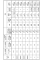
- 4 is a table showing evaluation results when the Tg of the acrylic resin of the first resin layer and the presence or absence of urethane cross-linking are changed.
- 4 is a table showing evaluation results when changing the mixing ratio of cellulose ester resin in the second resin layer. It is an evaluation result when changing the cellulose ester resin mixing ratio of the relief forming layer.
- 4 is a table showing the relationship between the cellulose ester resin mixing ratios of the second resin layer and the relief-forming layer.
- FIG. 7 is a list of failure details and presumed causes of each area shown in FIG. 6 ;
- FIG. 7 is a list of failure details and presumed causes of each area shown in FIG. 6 ;
- FIG. 7 is a list of failure details and presumed causes of each area shown in FIG. 6 ;
- FIG. 7 is a list of failure details and presumed causes of each area shown in FIG
- the material configuration according to the present invention brings about an improvement effect in the relief structure shaping accuracy, durability against heat and pressure, and transferability.
- the present invention solves the problem of reconciling conflicting physical properties such as relief structure shaping accuracy, durability against heat and pressure, and transferability in a transfer foil.
- An acrylic resin having a glass transition temperature Tg of 95° C. or higher is selected as the acrylic resin used for the first resin layer.
- the reason for this is to impart heat resistance to the transfer foil to the extent that the first resin layer unintentionally heat-dissolves during transfer, resulting in an increase in adhesion to the surface of the support, thereby preventing defective transfer. It is also for enhancing compatibility with the second resin layer to be laminated next.
- the acrylic resins produced by polymerization of methyl methacrylate (MMA) such acrylic resins are particularly susceptible to copolymerization or addition of butyl methacrylate (BMA), styrene, or other monomers in the functional group structure. , or have significantly less structure.
- the acrylic resin having such a structure has particularly excellent transparency and dimensional stability, is very hard and has a high melting point, and protects the relief structure provided in the transfer foil from external physical elements.
- acrylic resins free from copolymerization with other monomers have very good compatibility with cellulose ester resins. Furthermore, acrylic resin (refractive index of about 1.49) and cellulose ester (refractive index of about 1.46 to 1.50) have very close refractive indices. Therefore, attenuation of light intensity due to interfacial reflection with the second resin layer in contact with the first resin layer and intra-layer scattering inside the second resin layer is minimized. Further, the mixture of cellulose ester and acrylic resin reduces the adverse effects of cellulose ester birefringence.
- the above interface reflection, attenuation of light intensity, or reduction of birefringence is very effective in the sense that the optical effect brought about by the relief structure can be externally expressed without being attenuated.
- the second resin layer and the relief-forming layer are both a mixture of the above-mentioned acrylic resin and a cellulose ester resin in which a portion of the hydroxyl groups are urethane-crosslinked, and the melting point of the second resin layer is higher than the melting point of the relief-forming layer. is also a high layer structure. By setting it as such a layer structure, the following two effects are acquired.
- such a layer structure makes it possible to improve the processing accuracy of the relief structure and to impart extremely high heat resistance and pressure resistance to the transfer foil.
- the presence of the second resin layer, which has a higher melting point than the relief-forming layer, which is a feature of the present invention, provides a very effective durability effect.
- a second resin layer having a high melting point is in contact with the relief-forming layer and positioned between the relief-forming layer and the first resin layer. Part of the external heat and pressure applied to the relief forming layer diffuses into the second resin layer with a high melting point, reducing the thermal burden on the relief forming layer, and the external heat and pressure create an uneven relief structure. Gives an effect that makes it harder to destroy.
- the heat resistance of the transfer foil against external elements during thermocompression transfer and after application is remarkably improved.
- a relief forming layer using a material with a low melting point leads to a reduction in the processing temperature required for forming the relief structure, that is, facilitates relief shaping processing, and facilitates maintaining the accuracy of the relief structure stably and favorably.
- Such a layer structure can improve the heat resistance and pressure resistance of the transfer foil without impairing the transfer suitability.
- the second effect is particularly realized by mixing an acrylic resin and a cellulose ester resin in which a portion of the hydroxyl groups are urethane-crosslinked.
- Cellulose ester resin is obtained by esterifying a part of hydroxyl groups of glucose units, which are repeating units constituting cellulose. It has about 1 to 5% of hydroxyl groups that are not esterified.
- cellulose ester resin since cellulose ester resin generally forms a network of strong hydrogen bonds within and between molecular chains, it has a higher glass transition temperature (Tg: 95°C to 105°C) than acrylic resin ( Tg: about 130°C to 160°C), and has excellent heat resistance and impact resistance. On the other hand, it has poor thermoplasticity in the vicinity of transfer temperature conditions (100° C. to 150° C., about 0.1 to 1 second). This poor thermoplasticity causes problems such as cracks on the transfer surface and transfer burrs in a process in which heat and pressure are instantaneously applied, such as transfer of a transfer foil. More specifically, when a transfer foil having a layer composed only of cellulose ester resin is thermally and pressure-transferred, the temperature range (100° C.
- the Tg of the cellulose ester resin (approximately 130° C. to 160°C). That is, the cellulose ester resin layer is not partially melted and split by heat, but the foil is transferred by cracking and splitting the resin layer by pressure. Therefore, it is considered that problems such as cracks on the transfer surface and transfer burrs are likely to occur.
- the present invention provides a cellulose ester resin (Tg: about 130° C. to 160° C.) with thermoplasticity at a transfer temperature of around 100° C. to 120° C. by mixing with an acrylic resin and urethane crosslinking of hydroxyl groups. It has one feature.
- the imparting of thermoplasticity in the vicinity of the transfer temperature suppresses the occurrence of cracks and transfer burrs in thermal pressure transfer, and improves the transferability.
- urethanization of hydroxyl groups will be described in detail.
- One of the characteristics of the present invention is that some of the hydroxyl groups of the cellulose ester resin are urethane-crosslinked. Cellulose ester in a state not crosslinked with urethane is difficult to entangle and is easily softened.
- cross-linking with urethane can provide the required stiffness of cellulose esters.
- the thermoplasticity of the cellulose ester resin is improved in the transfer temperature range, which prevents cracks during transfer. give effect.
- a urethane crosslinked network is formed by about 1 to 5% by mass of the hydroxyl groups present inside the rigid molecular network of the cellulose ester.
- Changes in cross-linking density and volume shrinkage due to this urethane cross-linking reaction result in internal residual stress and residual strain in the material after curing.
- the effect of facilitating separation of the transfer foil from the support in accordance with the imprinted shape is produced during thermal pressure transfer. This effect is particularly effective in reducing transfer burrs.
- a preferred isocyanate is a toluenediisocyanate (TDI) system having a benzene ring structure.
- the TDI system tends to generate residual stress and residual strain inside the material after curing.
- the urethane group to be formed preferably has thermoplasticity (peak of decrease in flexural modulus) at a transfer temperature of about 100°C to 120°C.
- FIG. 1 is a cross-sectional view schematically showing a transfer foil according to an embodiment of the invention.
- the transfer foil 2 shown in FIG. 1 is provided on one side of the support 1 in a detachable state.
- the transfer foil 2 includes a first resin layer 3 , a second resin layer 4 , a relief forming layer 5 and an adhesive layer 7 in this order from the substrate 1 . Furthermore, it has a relief structure 6 and a reflective layer 8 between the relief-forming layer 5 and the adhesive layer 7 .
- a support 1 supports the transfer foil 2 until it is transferred to a transfer target.
- a plastic film can be used for the support 1 .
- Polyethylene terephthalate (PET), polyethylene naphthalate (PEN), polypropylene (PP), and the like can be used as the material for forming the plastic film.
- PET polyethylene terephthalate
- PEN polyethylene naphthalate
- PP polypropylene
- the material for forming the film is preferably a material that is unlikely to be deformed or deteriorated by heat or pressure applied to the support 1 when the transfer foil 2 is formed.
- paper, synthetic paper, plastic multilayer paper, resin-impregnated paper, etc. can be used in addition to the plastic film.
- the first resin layer 3 holds the transfer foil 2 so as not to separate from the support 1 until it is transferred to the transferred material. At the time of transfer, the first resin layer 3 is subjected to heat, pressure, or a force in the direction away from the support 1 generated when the adhesive layer 7 adheres to the object to be transferred. This serves to separate the transfer foil 2 from the support 1 . Furthermore, after the transfer, it has a function of protecting the surface so that the transfer foil 2 is not destroyed by external heat or impact.
- the material forming the first resin layer 3 is an acrylic resin having a glass transition temperature Tg of 95° C. or higher.
- acrylic resins produced by polymerization of methyl methacrylate (MMA) are particularly susceptible to copolymerization or addition of butyl methacrylate (BMA), styrene, or other monomers in the functional group structure. , or have significantly less structure.
- BMA butyl methacrylate
- the acrylic resin having such a structure has particularly excellent transparency, is very hard, and has a high melting point, so that it does not interfere with the optical effect of the relief structure.
- the transfer foil 2 is endowed with durability against external physical elements.
- a specific example of the material is Dianal BR-84 (Dianal is a registered trademark) manufactured by Mitsubishi Rayon Co., Ltd. (glass transition temperature: 105° C., weight average molecular weight: Mw: 120,000).
- the first resin layer 3 may contain an additive such as a lubricant.
- a lubricant polyethylene powder, paraffin wax, silicone, waxes such as carnauba wax, inorganic particles such as silica, and material deterioration inhibitors can be used.
- the amount of the additive is preferably about 0.1 to 10 when the weight solid content of the entire material constituting the first resin layer 3 is 100.
- the first resin layer 3 and the support 1 do not necessarily have to be in direct contact with each other.
- a new layer for assisting the function of the first resin layer 3 may be additionally provided between them.
- Specific examples of the layer to be added include a transferability improving layer using a sea-island structure made of wax, resin, or inorganic particles.
- the thickness of the first resin layer 3 is preferably about 0.2 ⁇ m to 3 ⁇ m.
- the second resin layer 4 is located between the first resin layer 3 and the relief-forming layer 5 and imparts high heat resistance and pressure resistance to the transfer foil 2 .
- the second resin layer 4 is composed of a mixture of an acrylic resin having a glass transition temperature Tg of 95° C. or higher and a cellulose ester resin in which a portion of the hydroxyl group is urethane-crosslinked, and the melting point of the second resin layer 4 is It is provided so as to be higher than the melting point of the relief forming layer 5 . That is, when the cellulose ester resin having the same glass transition temperature Tg is used for the second resin layer 4 and the relief forming layer 5, the cellulose ester resin ratio of the second resin layer 4 is higher than that of the relief forming layer 5.
- Examples of the cellulose ester resin used for the second resin layer 4 include cellulose acetate resin, cellulose acetate butyrate resin, cellulose acetate propionate resin, and cellulose nitrate.
- the cellulose ester resin has hydroxyl groups at a weight ratio of 1 to 5%.
- the effect of improving transferability is brought about by urethane-crosslinking the hydroxyl groups. This is because changes in the intralayer resin density and volume shrinkage due to the urethane cross-linking reaction result in internal material stress and residual strain in the layer, and the transfer foil separates from the support according to the imprinted shape during thermocompression transfer.
- the proportion of hydroxyl groups in the cellulose ester resin in the present invention is about 1 to 3%.
- a specific example of the material is CAB-381-2 (glass transition temperature 133° C., weight average molecular weight Mw 40000, hydroxyl group content 1.3%) manufactured by Eastman Chemical Co., Ltd.
- Diisocyanate can be mentioned as the isocyanate compound used for urethane crosslinking of hydroxyl groups.
- Diisocyanates include toluene diisocyanate (TDI) and hexamethylene diisocyanate (HDI).
- TDI toluene diisocyanate
- HDI hexamethylene diisocyanate
- a product of toluene diisocyanate can be exemplified by Coronate 2030 (Coronate is a registered trademark) manufactured by Nippon Polyurethane Industry Co., Ltd.
- a product of hexamethylene diisocyanate can be exemplified by Takenate D-160N (Takenate is a registered trademark) manufactured by Mitsui Chemicals, Inc.
- a diisocyanate having a benzene ring structure is preferable from the viewpoint of facilitating the generation of residual stress and residual strain in the layer after the cross-linking reaction.
- toluene diisocyanate having a benzene ring structure may also be used. Since the amount of hydroxyl groups contained in the second resin layer 4 is very small, ie, 5% or less by weight of the cellulose ester resin contained, the second resin layer 4 actually reacts with other functional groups before reacting with the desired hydroxyl groups.
- the amount of isocyanate necessary for urethane crosslinking to the extent that the effect can be sufficiently confirmed in the present invention is such that the molar ratio to the hydroxyl group (NCO/OH ratio) is 1.5 (the amount of isocyanate is 1.5 more than the amount of hydroxyl group). 5-fold excess) is preferred. Moreover, this molar ratio can be 1.0 or more and 3.0 or less.
- a specific example of the material is Coronate 2030 (Coronate is a registered trademark) manufactured by Nippon Polyurethane Industry Co., Ltd. (quick-drying type, NCO content: 8%, solid content: 50%).
- the number of functional groups in urethane is preferably 2-10, more preferably 1-5. 2 or 3 is particularly preferred.
- the relief forming layer 5 is provided so as to be in contact with the second resin layer 4 .
- the second resin layer 4 and the relief-forming layer 5 are made of the same material, and the melting point of the relief-forming layer 5 is lower than that of the second resin layer 4 .
- the heat resistance of the transfer foil 2 is maintained, and the processing temperature required for forming the relief structure 6 to be described later is reduced, that is, the relief shaping processing is facilitated. This facilitates maintaining the accuracy of the relief structure 6 stably and favorably.
- the acrylic resin and cellulose ester resin used for the relief-forming layer 5 and the second resin layer 4 meet the conditions of the present invention, that is, the Tg of the acrylic resin is 95° C. or higher.
- the second resin layer 4 and the relief-forming layer 5 may use cellulose ester resins having different glass transition points, molecular weights, or hydroxyl group amounts. However, in this case, it is necessary to select the materials while paying attention to their compatibility so as not to cause clouding due to mixing of the respective resins.
- the relief-forming layer 5 may contain an additive such as a lubricant in order to facilitate shaping of the relief structure 6 .
- a silicone-based additive, a fluorine-based additive, or the like can be used as the lubricant.
- the amount of the additive is preferably about 0.1 to 10 when the weight solid content of the entire material constituting the relief forming layer 5 is 100.
- the relief structure 6 is composed of fine irregularities. It has optical effects such as optical diffraction effect, selective reflection effect or non-reflection effect, isotropic or anisotropic scattering effect, condensing effect, polarized reflection effect. As a result, effects such as prevention of forgery and falsification and improvement of design properties can be obtained by visual inspection, machine detection, or the like.
- the relief structure 6 can consist of a combination of one or more optical effect reliefs.
- the relief structure 6 is usually formed with a specific period or a random pattern, with a difference in unevenness in the thickness direction of 0.01 ⁇ m to 10 ⁇ m and a period in the direction of surface spread of 0.01 ⁇ m to 10 ⁇ m.
- the reflective layer 8 is a layer provided to make the optical effect of the relief structure 6 easily observable.
- Materials for the reflective layer 8 include aluminum and transparent ceramic materials such as zinc sulfide and titanium dioxide.
- Aluminum is inexpensive, provides a highly glossy and opaque film, and is easy to handle.
- Transparent ceramic materials have a high refractive index for visible light and are easy to process. It is preferable to form the reflective layer 8 with a film thickness of 100 to 800 nm.
- the reflective layer 8 can be formed by a vacuum deposition method, a sputtering method, or the like.
- the adhesive layer 7 is provided to enable the transfer foil 2 to be attached to the object to be transferred.
- the adhesive layer 7 is in an inactive state at room temperature, but is activated by external factors such as heat and pressure, and exhibits an adhesive effect to the transferred material.
- a thermoplastic resin, a thermosetting resin, an ultraviolet curable resin, an electron beam curable resin, or the like can be used. More specifically, modified acrylic resins, polyester resins, and urethane resins can be exemplified.
- known printing methods such as gravure printing, flexographic printing, screen printing, and offset printing can be used. However, it is not limited to the exemplified method.
- the film thickness of each layer described above can be set to about 0.2 to 5 ⁇ m.
- FIG. 2 is a diagram schematically showing the relationship between temperature and elastic modulus of the second resin layer 4 and the relief-forming layer 5 in the present invention.
- the vertical axis is the bending elastic modulus (Kgf/cm 2 )
- the horizontal axis is the temperature (° C.)
- the second resin composed of a cellulose ester resin single layer, an acrylic resin single layer, and a mixture thereof
- FIG. 4 schematically shows the temperature dependence of the flexural modulus of the layer 4 and the relief-forming layer 5.
- FIG. Furthermore, a transfer condition area (a condition area where transferability is good) and a heat resistance area required for the transfer foil 2 are shown as rectangular areas specified by the temperature range and the bending elastic modulus range.
- An object of the present invention is to realize a transfer foil having a flexural modulus temperature dependence that includes both of these two regions.
- FIG. 2 shows the flexural elastic moduli of the second resin layer 4 and the relief forming layer 5 which are made of the material having the highest melting point in each layer of the transfer foil 2 .
- the flexural modulus of the cellulose ester resin single layer and the acrylic resin single layer rapidly decreases due to thermal softening after the temperature approaches the glass transition temperature Tg.
- the cellulose ester resin generally has a higher flexural modulus than the acrylic resin.
- Tg is higher than that of acrylic resin, the flexural modulus is lowered in a higher temperature range than that of acrylic resin.
- the behavior of the cellulose ester resin single layer has sufficient heat resistance because it overlaps part of the required heat resistance region. On the other hand, it does not overlap the transfer condition area. This is because the cellulose ester resin hardly lowers its elastic modulus at the transfer condition temperature, so that the layer is not easily separated during transfer. In other words, this indicates that the transfer foil is difficult to transfer according to its shape.
- the behavior of the acrylic resin single layer is the opposite of the cellulose ester resin single layer, overlapping the transfer condition area but not the necessary heat resistance area. This indicates that the transferability is good, but the heat resistance required as a transfer foil is not obtained.
- the inventor made the second resin layer 4 and the relief-forming layer 5 a mixture of an acrylic resin and a cellulose ester resin.
- the behavior of the second resin layer 4 and the relief-forming layer 5 was successfully made to have both advantages of the acrylic resin single layer and the cellulose ester resin single layer.
- the behaviors of the second resin layer 4 and the relief forming layer 5 are overlapped with both the transfer condition area and the required heat resistance area as shown in FIG.
- the acrylic resin contained in the layers is thermally softened in the transfer temperature range, resulting in a decrease in elastic modulus, thereby obtaining good transferability. be done.
- the cellulose ester resin contained in the layer does not soften excessively and maintains a constant elastic modulus, which is considered to realize a transfer foil having good heat resistance.
- a reflective layer 8 was formed on the relief structure 6 by vacuum deposition.
- Sample Nos. 2 to 5 shown in FIG. The acrylic resins used are shown below.
- ⁇ Sample number 2> Dianal BR-82 (Tg 95°C) manufactured by Mitsubishi Rayon Co., Ltd.
- ⁇ Sample No. 4> Dianal BR-101 (Tg 50°C) manufactured by Mitsubishi Rayon Co., Ltd. Copolymerization of MMA with other monomers
- ⁇ Sample No. 5> Dianal BR-1122 (Tg 20°C) manufactured by Mitsubishi Rayon Co., Ltd. MMA and Other Monomer Copolymerization
- Sample No. 6 was made similar to Sample No. 1, except that no isocyanate was added (ie, no urethane cross-linking).
- the transferred transfer foil 2 was visually observed, and the maximum length of the portion (transfer burr) different from the circular shape was evaluated. Measurements were taken from the point of contact of the circular profile to the furthest point of the transfer burr.
- the vertical transfer conditions are a transfer temperature of 110° C., a pressure of 300 kg/cm 2 and a transfer time of 1 second. Five samples were evaluated for each sample number, and evaluated in the following three stages. ⁇ (good): The maximum length of the transfer burr is less than 1 mm in all samples ⁇ (fair): Transfer burrs of 1 mm or more are found in some samples ⁇ (Bad): Transfer burrs of 1 mm or more are found in all samples admit
- sample numbers 1 and 2 gave good results in all evaluation items, while sample numbers 3 and 5 gave poor results in appearance and heat resistance.
- the appearance it is considered that the acryl resin contains copolymerization of other monomers, so that the compatibility with the resin deteriorates and cloudiness occurs. It was considered that the deterioration of the heat resistance was caused by the Tg of the acrylic resin being too low.
- sample numbers 4 and 5 transfer burrs became large. It is considered that the reason for this is that the Tg of the acrylic resin is too low and the first resin is dissolved by the heat during the transfer.
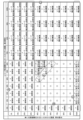
- sample numbers 16 to 19 In FIG. 5, except for sample numbers 16 to 19, poor results were obtained in either heat resistance, relief structure precision, or transferability.
- the mixture ratio of cellulose ester resin in the relief forming layer 5 is small (sample number 15), it is considered that the heat resistance of the relief forming layer 5 is insufficient due to the small ratio of the cellulose ester resin.
- the second resin layer 4 and the relief forming layer 5 have the same ratio of cellulose ester resin (sample number 20), or the ratio of cellulose ester resin is too high (sample number 21-22), which is thought to have caused the deterioration of relief structure accuracy and transferability.
- FIG. 6 is a table summarizing the results shown in FIGS. 3 to 5 in a matrix form based on the mixing ratio of the cellulose ester resin in the second resin layer 4 and the relief forming layer 5 . Areas where the evaluation results were poor are considered to be due to similar causes, and the estimated causes for each area are summarized in FIG. According to FIG. 6, the mixing ratio of the cellulose ester resin in the second resin layer 4 is 40% or more and 90% or less, and the mixing ratio in the relief forming layer 5 is 10% or more and 60% or less. Further, the mixing ratio of the cellulose ester resin in the second resin layer 4 should be higher than the mixing ratio of the cellulose ester resin in the relief forming layer 5 . The above conditions are considered to be the conditions under which the best evaluation results can be obtained.
- a transfer foil separably supported on a support The transfer foil has, in order from the support side, a first resin layer, a second resin layer, and a relief forming layer,
- the first resin layer is composed of an acrylic resin having a glass transition temperature Tg of 95° C. or higher
- the second resin layer and the relief-forming layer are composed of a mixture of the acrylic resin and a cellulose ester resin in which a portion of the hydroxyl groups are urethane-crosslinked,
- the melting point of the second resin layer is higher than the melting point of the relief-forming layer, transfer foil.
- the acrylic resin is a polymer in which only methyl methacrylate (MMA) monomers are polymerized.
- the mixing ratio of the cellulose ester resin in the second resin layer is higher than the mixing ratio of the cellulose ester resin in the relief-forming layer;
- the cellulose ester resin includes at least one of cellulose acetate butyrate, cellulose acetate propionate, and cellulose nitrate.
- the transfer foil according to any one of Inventions 1 to 3.
- the mixing ratio of the cellulose ester resin is 40% or more and 90% or less in the second resin layer, and 10% or more and 60% or less in the relief forming layer.
- the transfer foil according to any one of Inventions 1 to 4.
- the urethane crosslink has a benzene ring, The transfer foil according to any one of Inventions 1 to 5.
- the transfer foil Taking advantage of the characteristics of the transfer foil according to the present invention, it can be used as a transfer foil that has a relief structure and requires high durability, such as securities, bills, ID cards, passports, etc. is.
Landscapes
- Physics & Mathematics (AREA)
- General Physics & Mathematics (AREA)
- Optics & Photonics (AREA)
- Thermal Sciences (AREA)
- Decoration By Transfer Pictures (AREA)
- Laminated Bodies (AREA)
Priority Applications (3)
| Application Number | Priority Date | Filing Date | Title |
|---|---|---|---|
| JP2023542443A JPWO2023022201A1 (https=) | 2021-08-19 | 2022-08-18 | |
| KR1020237045097A KR20240042588A (ko) | 2021-08-19 | 2022-08-18 | 릴리프 구조를 갖는 전사박 |
| EP22858518.8A EP4390473B1 (en) | 2021-08-19 | 2022-08-18 | Relief structure-bearing transfer foil |
Applications Claiming Priority (2)
| Application Number | Priority Date | Filing Date | Title |
|---|---|---|---|
| JP2021-133833 | 2021-08-19 | ||
| JP2021133833 | 2021-08-19 |
Publications (1)
| Publication Number | Publication Date |
|---|---|
| WO2023022201A1 true WO2023022201A1 (ja) | 2023-02-23 |
Family
ID=85240829
Family Applications (1)
| Application Number | Title | Priority Date | Filing Date |
|---|---|---|---|
| PCT/JP2022/031240 Ceased WO2023022201A1 (ja) | 2021-08-19 | 2022-08-18 | レリーフ構造を有する転写箔 |
Country Status (4)
| Country | Link |
|---|---|
| EP (1) | EP4390473B1 (https=) |
| JP (1) | JPWO2023022201A1 (https=) |
| KR (1) | KR20240042588A (https=) |
| WO (1) | WO2023022201A1 (https=) |
Citations (6)
| Publication number | Priority date | Publication date | Assignee | Title |
|---|---|---|---|---|
| JP2002192895A (ja) * | 2000-12-27 | 2002-07-10 | Nikka Techno:Kk | 電磁波透過性金属蒸着ホログラム転写材とその製造方法 |
| JP2006309205A (ja) * | 2005-03-30 | 2006-11-09 | Dainippon Printing Co Ltd | 着色層転写材及びそれを用いた画像形成物 |
| JP2008162260A (ja) * | 2006-12-04 | 2008-07-17 | Dainippon Printing Co Ltd | ホログラム構造 |
| JP2010005888A (ja) * | 2008-06-26 | 2010-01-14 | Dainippon Printing Co Ltd | パッチ転写媒体の製造方法、パッチ転写媒体及びパッチ転写繊維質素材 |
| JP2016060046A (ja) * | 2014-09-12 | 2016-04-25 | 大日本印刷株式会社 | 熱転写シート、印画物及び画像形成方法 |
| JP2021133833A (ja) | 2020-02-27 | 2021-09-13 | 株式会社デンソー | 表示装置及び表示制御装置 |
Family Cites Families (2)
| Publication number | Priority date | Publication date | Assignee | Title |
|---|---|---|---|---|
| US7927711B2 (en) * | 2003-12-22 | 2011-04-19 | Sipix Chemical Inc. | Durable layer composition for in-mold decoration |
| EP1752307B1 (en) * | 2004-04-06 | 2014-04-30 | Dai Nippon Printing Co., Ltd. | Coloring material receptor sheet with relief layer, and image forming method using it |
-
2022
- 2022-08-18 KR KR1020237045097A patent/KR20240042588A/ko active Pending
- 2022-08-18 WO PCT/JP2022/031240 patent/WO2023022201A1/ja not_active Ceased
- 2022-08-18 JP JP2023542443A patent/JPWO2023022201A1/ja active Pending
- 2022-08-18 EP EP22858518.8A patent/EP4390473B1/en active Active
Patent Citations (6)
| Publication number | Priority date | Publication date | Assignee | Title |
|---|---|---|---|---|
| JP2002192895A (ja) * | 2000-12-27 | 2002-07-10 | Nikka Techno:Kk | 電磁波透過性金属蒸着ホログラム転写材とその製造方法 |
| JP2006309205A (ja) * | 2005-03-30 | 2006-11-09 | Dainippon Printing Co Ltd | 着色層転写材及びそれを用いた画像形成物 |
| JP2008162260A (ja) * | 2006-12-04 | 2008-07-17 | Dainippon Printing Co Ltd | ホログラム構造 |
| JP2010005888A (ja) * | 2008-06-26 | 2010-01-14 | Dainippon Printing Co Ltd | パッチ転写媒体の製造方法、パッチ転写媒体及びパッチ転写繊維質素材 |
| JP2016060046A (ja) * | 2014-09-12 | 2016-04-25 | 大日本印刷株式会社 | 熱転写シート、印画物及び画像形成方法 |
| JP2021133833A (ja) | 2020-02-27 | 2021-09-13 | 株式会社デンソー | 表示装置及び表示制御装置 |
Also Published As
| Publication number | Publication date |
|---|---|
| KR20240042588A (ko) | 2024-04-02 |
| EP4390473A1 (en) | 2024-06-26 |
| EP4390473A4 (en) | 2024-12-18 |
| JPWO2023022201A1 (https=) | 2023-02-23 |
| EP4390473B1 (en) | 2025-12-03 |
Similar Documents
| Publication | Publication Date | Title |
|---|---|---|
| US7420005B2 (en) | Photocurable resin composition, finely embossed pattern-forming sheet, finely embossed transfer sheet, optical article, stamper and method of forming finely embossed pattern | |
| TW445218B (en) | A transfer material and a surface protecting sheet excellent in abrasion resistance and chemical resistance, and method for producing molded article excellent in abrasion resistance and chemical resistance | |
| JP4275469B2 (ja) | 凹凸パターン形成材料、凹凸パターン受容体、凹凸パターン形成方法、転写箔、及び光学物品 | |
| JP4197240B2 (ja) | 光硬化性樹脂、光硬化性樹脂組成物、微細凹凸パターン形成方法、転写箔、光学物品及びスタンパー | |
| JP4324374B2 (ja) | 微細凹凸パターン形成材料、微細凹凸パターン形成方法、転写箔、光学物品及びスタンパー | |
| KR102485172B1 (ko) | 핫 스탬핑박 및 적층 광학 장식체 구비 인쇄체 | |
| TWI421164B (zh) | 轉印薄片及轉印薄片之製造方法 | |
| KR102508581B1 (ko) | 위조 방지 구조체 | |
| JP7044068B2 (ja) | 転写箔、セキュリティ積層体、および、セキュリティ積層体の製造方法 | |
| JP2007118563A (ja) | 転写箔及びそれを用いた画像形成物 | |
| JP2009018468A (ja) | ホログラム転写箔及びスクラッチカード | |
| WO2006095902A1 (ja) | 転写箔及びそれを用いた画像形成物 | |
| JP4453945B2 (ja) | 転写箔シート及びその剥離性・破断性の評価方法 | |
| WO2023022201A1 (ja) | レリーフ構造を有する転写箔 | |
| JP6459163B2 (ja) | Ovd転写箔 | |
| JP4012164B2 (ja) | 転写シート、その製造方法、及び中間転写記録媒体 | |
| JP2003162205A (ja) | 光硬化性樹脂組成物、シート、転写箔、微細凹凸パターン形成方法、及び光学用物品 | |
| WO2006085597A1 (ja) | 複数図柄光輝性フィルム、複数図柄光輝性スレッドおよびそれらを用いた光輝性複数図柄形成物 | |
| JP4770342B2 (ja) | ホログラム付き収縮フィルムの製造方法 | |
| JP3585748B2 (ja) | 転写材、および転写材を用いた耐候性、耐磨耗性および耐薬品性に優れた成形品の製造方法 | |
| JP2008007638A (ja) | 転写箔用の接着層組成物 | |
| JP2004123831A (ja) | 光硬化性樹脂組成物、微細凹凸パターン転写箔、光学物品、スタンパー及び微細凹凸パターンの形成方法 | |
| JP2016114853A (ja) | 貼り替え対策シール及び貼り替え対策シール付き物品 | |
| JP2005104043A (ja) | 熱転写シート | |
| JP2007225639A (ja) | 複数ホログラム転写箔、及びそれを用いた複数ホログラム形成物。 |
Legal Events
| Date | Code | Title | Description |
|---|---|---|---|
| 121 | Ep: the epo has been informed by wipo that ep was designated in this application |
Ref document number: 22858518 Country of ref document: EP Kind code of ref document: A1 |
|
| WWE | Wipo information: entry into national phase |
Ref document number: 2023542443 Country of ref document: JP |
|
| WWE | Wipo information: entry into national phase |
Ref document number: 2022858518 Country of ref document: EP |
|
| NENP | Non-entry into the national phase |
Ref country code: DE |
|
| ENP | Entry into the national phase |
Ref document number: 2022858518 Country of ref document: EP Effective date: 20240319 |
|
| WWG | Wipo information: grant in national office |
Ref document number: 2022858518 Country of ref document: EP |