WO2023022098A1 - 検査システム - Google Patents
検査システム Download PDFInfo
- Publication number
- WO2023022098A1 WO2023022098A1 PCT/JP2022/030662 JP2022030662W WO2023022098A1 WO 2023022098 A1 WO2023022098 A1 WO 2023022098A1 JP 2022030662 W JP2022030662 W JP 2022030662W WO 2023022098 A1 WO2023022098 A1 WO 2023022098A1
- Authority
- WO
- WIPO (PCT)
- Prior art keywords
- conductive
- circuit
- inspection system
- rfid
- antenna
- Prior art date
- Legal status (The legal status is an assumption and is not a legal conclusion. Google has not performed a legal analysis and makes no representation as to the accuracy of the status listed.)
- Ceased
Links
Images


Classifications
-
- B—PERFORMING OPERATIONS; TRANSPORTING
- B64—AIRCRAFT; AVIATION; COSMONAUTICS
- B64F—GROUND OR AIRCRAFT-CARRIER-DECK INSTALLATIONS SPECIALLY ADAPTED FOR USE IN CONNECTION WITH AIRCRAFT; DESIGNING, MANUFACTURING, ASSEMBLING, CLEANING, MAINTAINING OR REPAIRING AIRCRAFT, NOT OTHERWISE PROVIDED FOR; HANDLING, TRANSPORTING, TESTING OR INSPECTING AIRCRAFT COMPONENTS, NOT OTHERWISE PROVIDED FOR
- B64F5/00—Designing, manufacturing, assembling, cleaning, maintaining or repairing aircraft, not otherwise provided for; Handling, transporting, testing or inspecting aircraft components, not otherwise provided for
- B64F5/60—Testing or inspecting aircraft components or systems
-
- B—PERFORMING OPERATIONS; TRANSPORTING
- B64—AIRCRAFT; AVIATION; COSMONAUTICS
- B64C—AEROPLANES; HELICOPTERS
- B64C1/00—Fuselages; Constructional features common to fuselages, wings, stabilising surfaces or the like
- B64C1/06—Frames; Stringers; Longerons ; Fuselage sections
- B64C1/12—Construction or attachment of skin panels
-
- B—PERFORMING OPERATIONS; TRANSPORTING
- B64—AIRCRAFT; AVIATION; COSMONAUTICS
- B64D—EQUIPMENT FOR FITTING IN OR TO AIRCRAFT; FLIGHT SUITS; PARACHUTES; ARRANGEMENT OR MOUNTING OF POWER PLANTS OR PROPULSION TRANSMISSIONS IN AIRCRAFT
- B64D45/00—Aircraft indicators or protectors not otherwise provided for
-
- G—PHYSICS
- G01—MEASURING; TESTING
- G01M—TESTING STATIC OR DYNAMIC BALANCE OF MACHINES OR STRUCTURES; TESTING OF STRUCTURES OR APPARATUS, NOT OTHERWISE PROVIDED FOR
- G01M17/00—Testing of vehicles
- G01M17/007—Wheeled or endless-tracked vehicles
-
- G—PHYSICS
- G01—MEASURING; TESTING
- G01M—TESTING STATIC OR DYNAMIC BALANCE OF MACHINES OR STRUCTURES; TESTING OF STRUCTURES OR APPARATUS, NOT OTHERWISE PROVIDED FOR
- G01M17/00—Testing of vehicles
- G01M17/08—Railway vehicles
-
- G—PHYSICS
- G01—MEASURING; TESTING
- G01M—TESTING STATIC OR DYNAMIC BALANCE OF MACHINES OR STRUCTURES; TESTING OF STRUCTURES OR APPARATUS, NOT OTHERWISE PROVIDED FOR
- G01M5/00—Investigating the elasticity of structures, e.g. deflection of bridges or air-craft wings
- G01M5/0033—Investigating the elasticity of structures, e.g. deflection of bridges or air-craft wings by determining damage, crack or wear
-
- G—PHYSICS
- G01—MEASURING; TESTING
- G01M—TESTING STATIC OR DYNAMIC BALANCE OF MACHINES OR STRUCTURES; TESTING OF STRUCTURES OR APPARATUS, NOT OTHERWISE PROVIDED FOR
- G01M5/00—Investigating the elasticity of structures, e.g. deflection of bridges or air-craft wings
- G01M5/0091—Investigating the elasticity of structures, e.g. deflection of bridges or air-craft wings by using electromagnetic excitation or detection
-
- G—PHYSICS
- G06—COMPUTING OR CALCULATING; COUNTING
- G06K—GRAPHICAL DATA READING; PRESENTATION OF DATA; RECORD CARRIERS; HANDLING RECORD CARRIERS
- G06K19/00—Record carriers for use with machines and with at least a part designed to carry digital markings
- G06K19/06—Record carriers for use with machines and with at least a part designed to carry digital markings characterised by the kind of the digital marking, e.g. shape, nature, code
- G06K19/067—Record carriers with conductive marks, printed circuits or semiconductor circuit elements, e.g. credit or identity cards also with resonating or responding marks without active components
- G06K19/07—Record carriers with conductive marks, printed circuits or semiconductor circuit elements, e.g. credit or identity cards also with resonating or responding marks without active components with integrated circuit chips
- G06K19/077—Constructional details, e.g. mounting of circuits in the carrier
Definitions
- Patent Documents 1 and 2 disclose defect detection using an RFID or the like.
- Patent Document 1 describes that defect detection is performed by RFID, it is a method using non-destructive inspection, and accuracy that can accurately detect damage on the order of several millimeters in a moving body structure such as an aircraft cannot be expected.
- Patent Document 2 also proposes a combination of a damage detection method involving destruction of a conductor circuit and a wireless communication device. It takes time.
- Patent Document 2 does not specifically disclose the strength of the insulating film and the conductor circuit, their interfaces, and their relationship.
- the strength of the insulating film or interface is weaker than the strength of the conductor circuit, even if damage occurs in the base material, the damage will only spread within the insulator or at the interface, and the damage will not be able to propagate to the conductor circuit. It is not always possible to detect damage with the desired accuracy. Therefore, there is room for improvement in the materials of the detection circuit and the cross-sectional shapes of the components. In addition, since there is no disclosure of specific values for circuit dimensions, there is a possibility that protruding outside the installation target will increase air resistance, interfere with surrounding structures, and cause deterioration in appearance. In addition, in order to drive the sensor connected to the circuit, it is necessary to prepare a receiver separate from the transponder and supply power.
- the RF antenna that constitutes the RFID tag is placed in close proximity to a conductor such as metal or CFRP, the radio waves emitted from the RFID reader will not penetrate the RF antenna and communication will not be established. are doing.
- An object of the present invention is to provide an inspection system capable of achieving detection accuracy suitable for maintaining structural integrity.
- a first aspect of the present disclosure is an inspection system applied to a moving body, provided on an insulating coating or a non-conductive coating on the structural surface of the moving body, and the insulating coating or the non-conductive coating
- An inspection system comprising: an RFID IC chip that includes a closely attached conductive circuit, a sensor terminal connected to the conductive circuit, and an RF antenna terminal connected to an RF antenna, and detects a continuity state of the conductive circuit. is.
- adjusting the material, shape, and strength of the conductive circuit of the inspection system laying the conductive circuit in close contact with the surface of the moving object using a specific conductive paint, conductive powder, or adhesive, This has the effect of improving the damage detection accuracy of the inspection system.
- the conductive circuit used in the inspection system is thin or narrow, it is possible to suppress interference with surrounding structures, increase in air resistance, and deterioration in appearance when the circuit is installed.
- the RFID chip used in the inspection system has a communication function and an inspection function of the damage detection circuit, there is an effect that the simplification, weight reduction, and miniaturization of the entire device can be realized.
- there is an effect that remote inspection using an RFID reader and an RFID chip is possible even for an object to be inspected, such as metal or CFRP, which does not transmit radio waves.
- FIG. 1 is a diagram showing a schematic configuration of an inspection system according to an embodiment of the present disclosure
- FIG. 1 is a diagram showing a schematic configuration of an inspection system according to an embodiment of the present disclosure
- FIG. FIG. 4 is a diagram showing an example of a case where a disconnection occurs in a circuit according to an embodiment of the present disclosure
- 1 illustrates an example RFID reader according to an embodiment of the present disclosure
- FIG. FIG. 2 is a diagram illustrating an example of circuit installation according to an embodiment of the present disclosure
- FIG. 2 is a diagram illustrating an example of circuit installation according to an embodiment of the present disclosure
- FIG. 4 is a diagram showing an example of cracks
- 1 is a BB cross-sectional view of an RFID tag according to an embodiment of the present disclosure
- FIG. 2A is a cross-sectional view of a circuit according to an embodiment of the present disclosure
- FIG. 2A is a cross-sectional view of a circuit according to an embodiment of the present disclosure
- FIG. 2A is a cross-sectional view of a circuit according to an embodiment of the present disclosure
- FIG. 2A is a cross-sectional view of a circuit according to an embodiment of the present disclosure
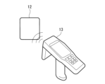
- FIG. 1A and 1B are diagrams showing a schematic configuration of an inspection system 10 according to the first embodiment of the present disclosure.
- the inspection system 10 is applied to mobile objects.
- FIG. 1A shows an example in which an inspection system 10 is provided for a fuselage skin 20 of an aircraft 31 .
- the inspection system 10 is not limited to the aircraft 31, and can be applied to various moving bodies such as trains, spacecraft, vehicles, and watercraft.
- an inspection system 10 includes a circuit (conductive circuit, electric circuit) 11 and an RFID tag 12 as main components.
- the circuit 11 is provided on the outer surface of the moving body and is composed of conductive paint, conductive powder, metal thin film, or small-diameter metal wire. Circuit 11 is electrically conductive.
- the circuit 11 is specifically configured as follows.
- a non-conductive layer of a non-conductive coating (insulating coating) or a non-conductive coating (non-conductive oxide coating) is formed as a base material on the structural surface (outer surface) of the aircraft 31 . That is, the structural surfaces of the aircraft 31 are electrically insulated from the exterior while in intimate contact with the non-conductive layer.
- the circuit 11 is directly formed using a conductive paint on top of a non-conductive layer of non-conductive paint or non-conductive coating (outside, outside the structure of the aircraft 31), cured and adhered.
- circuit 11 is formed by a conductive powder deposited over a non-conductive layer of non-conductive paint or coating.
- circuit 11 may be formed of thin metal film or small diameter metal wire and secured by an adhesive applied over a non-conductive layer of non-conductive paint or coating. That is, the structural surface of the aircraft 31 and the circuit 11 are structurally joined while being electrically insulated by a non-conductive layer of non-conductive paint or coating.
- the circuit 11 is formed to have a predetermined circuit diagram for each part of the aircraft 31, and both ends thereof are coupled to sensor terminals of the RFID chip 14, which will be described later.
- non-conducting coatings include anodizing on aluminum alloys and passivating coatings on stainless steel, but are not limited to these.
- adhesives examples include cyanoacrylate adhesives and epoxy adhesives, but are not limited to these.
- a conductive paint is, for example, a mixture of organic paint as a solvent and graphite powder, silver powder, or a conductive polymer (a high-molecular organic compound with conductivity, a conductive molecule, or a single conductive molecule) as a solute.
- Conductive paint is in a liquid state when applied, and may be divided into a main agent and a hardener.
- a circuit pattern can be freely created according to the shape of the object to be inspected by spraying or brushing. , resulting in a solid-state circuit with Since the circuit 11 is composed of conductive paint, the circuit 11 has appropriate elasticity and adhesion to non-conductive paint or non-conductive coating, so it is resistant to slight deformation of the outer surface of the aircraft 31.
- the circuit 11 can be configured so that it does not disconnect, and the circuit 11 disconnects when there is a large deformation of the outer surface or a crack in the outer surface.
- the paint may be designed so that the circuit 11 breaks when the outer surface is deformed by a predetermined amount or more or when the outer surface is cracked.
- the circuit 11 by configuring the circuit 11 using conductive paint, conductive powder, metal thin film, or small-diameter metal wire, the elasticity of the material can be used to improve the precision (accuracy) of detection.
- the RFID tag 12 includes an RFID chip 14, an RF antenna 15, a sensor terminal 16, and a non-conductive base 17.
- the RFID chip 14 has a sensor terminal (not shown) and an antenna terminal (not shown).
- the RFID chip 14 is connected to the circuit 11 via the sensor terminal 16 and connected to the RF antenna 15 via the antenna terminal.
- RFID chip 14 detects the conduction state of circuit 11 .
- the RF antenna 15 mediates communication (signal transmission/reception) and power supply between the RFID chip 14 and the outside.
- FIG. 2 is a diagram illustrating an example when a disconnection occurs in a circuit according to an embodiment of the present disclosure.
- FIG. 2 shows a case where the circuit 11 is configured to surround the supporting portion of the window 21 in the fuselage skin 20 of the aircraft 31 .
- the supporting portion of the window 21 is also the opening of the fuselage skin 20, and stress concentration occurs.
- Circuit 11 is therefore preferably provided to pass between window 21 and fastener 22 .
- FIG. 2 shows the case where the circuit 11 is disconnected.
- a crack may occur in the outer surface of the fuselage skin 20 from the frame of the window 21 toward the fastener 22, as shown at location 23 in FIG.
- the circuit 11 is disconnected, resulting in a disconnection state.
- the RFID chip 14 detects the conduction state of the circuit 11 based on, for example, whether or not a current flows through the circuit 11 (current value), the electrical resistance value of the circuit 11, and the like.
- the continuity detection method is not limited to these.
- the continuity state is explained as whether or not the circuit 11 is disconnected, but the state between the state in which there is no disconnection and the state in which the disconnection is completely disconnected is detected as the damaged state of the circuit 11. It's good as a thing. Damage status can also be determined by the conduction status of circuit 11 .
- FIG. 7 is a BB cross-sectional view of an RFID tag according to an embodiment of the present disclosure. As shown in FIG. 7, the RF antenna 15 is held at a position appropriately spaced from the installation target surface (structure) by a non-conductive pedestal 17 . As a result, even if the installation target surface of the RFID tag 12 is a metal or CFRP conductor that does not transmit radio waves, the RF antenna 15 maintains a state in which it can transmit and receive radio waves.
- the RFID tag 12 is installed, for example, by attaching it to the outer surface of the aircraft 31 .
- the RFID tag 12 is wirelessly supplied with power from an RFID reader 13, which will be described later. This power is used to detect the conduction state of the circuit 11, and the detection result is sent to the RFID reader 13 together with the unique identification information in the RFID chip 14. to send.
- the RFID chip 14 is provided with an anti-interference device, and even if a plurality of RFID tags 12 exist within the radio wave transmission range of the RFID reader 13, the RFID reader 13 can read them all at once.
- the RFID reader 13 wirelessly supplies power to the RFID tag 12 and receives information from the RFID tag 12 . Specifically, power is supplied from the RFID reader 13 to the RFID tag 12, and an instruction signal is transmitted to the RFID tag 12 to detect the conduction state of the circuit 11 and transmit the detection result. Along with this, the RFID chip 14 constituting the RFID tag 12 is charged with the received power, performs detection processing according to the instruction signal, and collects the detection result together with the unique identification information in the RFID chip 14 to the RFID reader 13. Send. As a result, the RFID reader 13 can read the conduction state of the circuit 11 detected by the RFID tag 12 at a specific location.
- the outer surface of the aircraft 31 is coated with a non-conductive paint (such as an insulating rust-preventive paint) or a non-conductive coating to form an insulating region for the outer surface as a base (non-conductive layer). Then, a circuit 11 is formed on this insulating area and an RFID tag 12 is installed. Circuit 11 is adhered to the outer surface of aircraft 31 . Therefore, a non-conductive layer, a layer of the circuit 11 and the RFID tag 12, and a non-conductive atmosphere are laminated in this order from the outer surface of the aircraft 31 toward the outside. That is, the circuit 11 is electrically insulated by a non-conductive member.
- a non-conductive paint such as an insulating rust-preventive paint
- a non-conductive coating such as an insulating rust-preventive paint
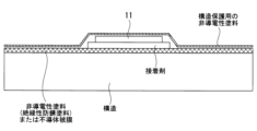
- FIG. 8 is a cross-sectional view AA of a circuit according to one embodiment of the present disclosure.
- the circuit 11 shown in FIG. 8 is formed by a conductive paint or conductive powder on top of a non-conductive layer (outside, outside the structure of the aircraft 31) of non-conductive paint or coating.
- FIG. 9 is a cross-section AA of a circuit according to one embodiment of the present disclosure.
- the circuit 11 shown in FIG. 9 is formed of a metal thin film or a small-diameter metal wire.
- FIG. 10 is a cross-sectional view AA of a circuit according to one embodiment of the present disclosure.
- the circuit 11 shown in FIG. 10 is formed by a conductive paint or powder on top of a non-conductive layer (outside, outside the structure of the aircraft 31) of non-conductive paint or coating. The entire circuit 11 is covered with non-conductive paint for structural protection.
- FIG. 11 is a cross-sectional view AA of a circuit according to one embodiment of the present disclosure.
- circuit 11 is formed by a metal thin film or a small-diameter metal wire.
- Circuit 11 is secured by an adhesive applied over a non-conductive layer of non-conductive paint or coating.
- the entire circuit 11 is covered with non-conductive paint for structural protection.
- the surface can be smoothed by suppressing steps while maintaining an economically valuable appearance. Therefore, it can be applied to moving objects sensitive to the influence of air resistance (for example, high-speed moving objects) and to moving objects whose appearance is important (for example, sports cars).
- a predetermined area including the installation area of the circuit 11 and the RFID tag 12 and other areas may be covered with a continuous non-conductive heat insulating material for heat retention. While maintaining the thermal environment inside the moving body, the surface can be smoothed by suppressing steps. Therefore, it can be applied to mobile objects (such as rockets and hydrogen aircraft) that are sensitive to the effects of air resistance.
- Non-conductive paints for structural protection include, but are not limited to, polyurethane enamels and epoxy primers.
- non-conductive heat insulating materials for heat retention include urethane foam heat insulating materials and glass wool, but are not limited to these.
- the RFID tag 12 It is preferable to mark the position where the RFID tag 12 is installed after covering it with a non-conductive paint for structural protection so that it can be recognized from the outside. Moreover, it is preferable to record in advance a combination of the installation position of the RFID tag 12 and the unique identification information in the RFID chip 14 of the RFID tag 12 .
- the circuit 11 Since the inspection system 10 detects damage to the outer surface of the aircraft 31, the circuit 11 is preferably located where damage is expected to occur.
- the places where damage is likely to occur are, for example, cutout positions (ends of members) and places where high stress occurs (places where stress concentration tends to occur). In other words, it is preferable to provide the circuit 11 around the cutout position and the stress concentrated portion.
- FIG. 4 is a diagram showing an example when the circuit 11 is installed on the aircraft 31.
- FIG. 4 shows an example of a circuit 11 provided around a cut-out location in the aircraft structure.
- the circuit 11 includes a window (for example, a cabin window) 21 of an aircraft 31, a cockpit windshield 24 of the aircraft 31, a door (door) 25, a door (emergency exit) 26, and an antenna attachment point on an outer surface. 27.
- the circuit 11 may be provided so as to pass through the vicinity of the fastener fastening portion (fastener portion) 28 on the outer surface (the range where the crack is expected to grow).
- the fastener fastening portion 28 is a joint portion between members constituting the aircraft 31, and particularly refers to a portion around an opening opened in the member and a portion provided with the fastener 22 to be inserted therein.
- FIG. 5 is a diagram showing an example in which the circuit 11 is installed on the aircraft 31.
- FIG. 5 is a view of the aircraft 31 viewed from below.
- FIG. 5 shows an example in which a circuit 11 is provided around a stress concentration point in an aircraft structure.
- the circuit 11 is provided so as to surround the manhole 41 .
- the circuit 11 is provided so as to pass through the vicinity (range where crack growth is expected) of each of the connecting portion 42 of the wing body, the mounting portion 43 of the landing gear, and the fitting portion 44 .
- the manhole 41 is an opening for accessing the inside and is closed with a lid.
- the metal fittings are metal fittings attached to the aircraft 31 .
- the neighborhood is a range of 2.5 cm from the end (or joint) of the part where the circuit 11 is provided.
- Fig. 6 shows an example of cracks.
- the circuit 11 is disconnected due to the damage and detected by the RFID tag 12 .
- the installation location of the circuit 11 illustrated in FIGS. 4 and 5 is not limited to the aircraft 31 and may be applied to other moving bodies as long as they have the same configuration. Also, the position where the circuit 11 is installed is not limited to the outer surface, and it may be installed inside the mobile structure.
- circuit 11 made of conductive paint, conductive powder, a metal thin film, or a small-diameter metal wire and an RFID tag 12
- protrusions on the outer surface of the moving body are minimized to suppress an increase in air resistance of the moving body. be able to.
- the circuit 11 is cut along the outer surface of the moving body by forming the circuit 11 with conductive paint, conductive powder, metal thin film, or small-diameter metal wire.
- the elasticity of the material maintains the conductive state of the circuit 11, thereby suppressing erroneous detection of damage.
- the circuit 11, the RFID tag 12, and a predetermined area around the circuit 11 and the RFID tag 12 on the outer surface of the moving body and other areas are continuously covered with an exterior material such as non-conductive paint or non-conductive heat insulating material. Therefore, it is possible to suppress steps on the surface and smooth the surface. In addition, both are possible without impairing economic efficiency and functionality such as appearance and heat insulation.
- An inspection system includes a conductive circuit provided on an insulating paint or a non-conductive film on a structural surface of a moving body and in close contact with the insulating paint or the non-conductive film; and a sensor connected to the conductive circuit. and an RF antenna terminal connected to an RF antenna, and an RFID IC chip for detecting the conduction state of a conductive circuit. Therefore, by detecting the conduction state (disconnection, resistance, etc.) of the conductive circuit with the RFID chip, it is possible to detect the state of cracks on the surface of the moving body. Since the status can be read by the RFID chip, inspection can be made more efficient. It is possible to increase the frequency of inspections, and an improvement in safety can be expected. In addition, since the non-conductive pedestal holds the sensor terminal, the RF antenna and the RFID chip, remote inspection using the RFID reader and the RFID chip is possible even for an object to be inspected, such as metal or CFRP, which does not transmit radio waves.
- the conductive circuit and the RFID chip provided on the insulating paint or the non-conductive film on the structural surface of the moving object and in close contact with the insulating paint or the non-conductive film the step on the surface of the moving object is suppressed. It is possible to suppress an increase in air resistance of the moving body.
- the insulating paint or non-conductive coating may have interfacial strength to adhere to the moving object.
- the insulating paint or non-conductive coating has an interfacial strength such that the insulating paint or non-conductive coating adheres to the moving body, so that the insulating coating or non-conductive coating is a layer that protects the structure of the moving body from corrosion and external damage. can be configured.
- the conductive circuit is formed by a conductive paint that is an organic compound solvent that uses conductive molecules or conductive single atoms as a solute and adheres to the insulating paint or non-conductive film when cured.
- a conductive paint that is an organic compound solvent that uses conductive molecules or conductive single atoms as a solute and adheres to the insulating paint or non-conductive film when cured.
- the conductive circuit can be attached to an insulating paint or a non-conductive coating, and is formed of a conductive powder in which conductive molecules or conductive single atoms account for 50% or more of the composition. may be
- a conductive circuit can be attached to an insulating paint or a non-conductive coating, and is formed of a conductive powder in which conductive molecules or conductive single atoms account for 50% or more of the composition. This creates a circuit that has the property of being adherent as it is formed, in addition to being conductive.
- the conductive circuit is formed by a metal thin film with a thickness of 70 ⁇ m or less or a metal wire with a diameter of 200 ⁇ m or less bonded to an insulating paint or non-conductive coating via an adhesive. Therefore, it is possible to control the dimension of the metal thin film or metal wire to a certain level or less so that the interface strength of the adhesive is superior, and to ensure the detection of damage.
- the RFID chip may receive power and transmit and receive signals wirelessly via an RF antenna to detect whether or not a conductive circuit is disconnected.
- the inspection system it is possible to detect cracks on the surface of the mobile object by detecting whether or not the RFID chip has caused a circuit breakage.
- the surface of the moving object is smoothed by suppressing steps.
- the RFID reader can read the conduction state of the conductive circuit detected by the RFID chip.
- the inspection system according to the present disclosure may include a non-conductive pedestal that holds the RF antenna and the RFID chip. According to the inspection system according to the present disclosure, since a non-conductive pedestal with appropriate dimensions is applied between the RF antenna and the structure to be inspected, even an inspection object such as metal or CFRP that does not transmit radio waves can be used as an RFID reader. Remote inspection using the RFID chip becomes possible, and power reception and signal transmission/reception capability from the RF reader can be improved.
Landscapes
- Engineering & Computer Science (AREA)
- Physics & Mathematics (AREA)
- Aviation & Aerospace Engineering (AREA)
- General Physics & Mathematics (AREA)
- Electromagnetism (AREA)
- Manufacturing & Machinery (AREA)
- Transportation (AREA)
- Computer Hardware Design (AREA)
- Microelectronics & Electronic Packaging (AREA)
- Theoretical Computer Science (AREA)
- Mechanical Engineering (AREA)
- Investigating Or Analyzing Materials By The Use Of Electric Means (AREA)
Priority Applications (2)
| Application Number | Priority Date | Filing Date | Title |
|---|---|---|---|
| JP2023542379A JP7725596B2 (ja) | 2021-08-17 | 2022-08-10 | 検査システム |
| US18/683,089 US20240344922A1 (en) | 2021-08-17 | 2022-08-10 | Inspection system |
Applications Claiming Priority (4)
| Application Number | Priority Date | Filing Date | Title |
|---|---|---|---|
| JP2021132689 | 2021-08-17 | ||
| JP2021-132689 | 2021-08-17 | ||
| JP2022086029 | 2022-05-26 | ||
| JP2022-086029 | 2022-05-26 |
Publications (1)
| Publication Number | Publication Date |
|---|---|
| WO2023022098A1 true WO2023022098A1 (ja) | 2023-02-23 |
Family
ID=85240698
Family Applications (1)
| Application Number | Title | Priority Date | Filing Date |
|---|---|---|---|
| PCT/JP2022/030662 Ceased WO2023022098A1 (ja) | 2021-08-17 | 2022-08-10 | 検査システム |
Country Status (3)
| Country | Link |
|---|---|
| US (1) | US20240344922A1 (https=) |
| JP (1) | JP7725596B2 (https=) |
| WO (1) | WO2023022098A1 (https=) |
Cited By (1)
| Publication number | Priority date | Publication date | Assignee | Title |
|---|---|---|---|---|
| CN115535292A (zh) * | 2022-09-13 | 2022-12-30 | 大连长丰实业总公司 | 一种交互式应急起落架开关检测系统 |
Citations (7)
| Publication number | Priority date | Publication date | Assignee | Title |
|---|---|---|---|---|
| JPS6262252U (https=) * | 1985-10-08 | 1987-04-17 | ||
| US5969260A (en) * | 1998-03-30 | 1999-10-19 | Mcdonnell Douglas Corporation | Remotely interrogatable apparatus and method for detecting defects in structural members |
| US20080223152A1 (en) * | 2005-12-14 | 2008-09-18 | The Boeing Company | Methods and systems for using active surface coverings for structural assessment and monitoring |
| US20110291802A1 (en) * | 2010-06-01 | 2011-12-01 | The Boeing Company | Structural health management device and associated system and method |
| JP2016040669A (ja) * | 2014-08-12 | 2016-03-24 | 東芝テック株式会社 | パッシヴ型ひび割れセンサ |
| JP2016136127A (ja) * | 2014-07-22 | 2016-07-28 | ザ・ボーイング・カンパニーThe Boeing Company | 鈍的衝撃を示す方法 |
| JP2020140605A (ja) * | 2019-03-01 | 2020-09-03 | トッパン・フォームズ株式会社 | 亀裂検知用ラベル |
Family Cites Families (8)
| Publication number | Priority date | Publication date | Assignee | Title |
|---|---|---|---|---|
| US6617963B1 (en) * | 1999-02-26 | 2003-09-09 | Sri International | Event-recording devices with identification codes |
| JP2006134249A (ja) | 2004-11-09 | 2006-05-25 | Fujitsu Ltd | Rfidタグ |
| WO2007085070A1 (en) * | 2006-01-26 | 2007-08-02 | National Research Council Of Canada | Surface-mounted crack detection |
| US8085165B2 (en) * | 2007-02-09 | 2011-12-27 | Luna Innovations Incorporated | Wireless corrosion sensor |
| US8040243B2 (en) * | 2008-11-18 | 2011-10-18 | The Boeing Company | RFID-based corrosion and moisture detection |
| US8886388B2 (en) * | 2009-06-29 | 2014-11-11 | The Boeing Company | Embedded damage detection system for composite materials of an aircraft |
| US20170167932A1 (en) * | 2015-12-10 | 2017-06-15 | The Trustees Of The Stevens Institute Of Technology | Integrated sensors for structural health monitoring |
| JP7084269B2 (ja) | 2018-09-26 | 2022-06-14 | トッパン・フォームズ株式会社 | 非接触通信媒体 |
-
2022
- 2022-08-10 JP JP2023542379A patent/JP7725596B2/ja active Active
- 2022-08-10 WO PCT/JP2022/030662 patent/WO2023022098A1/ja not_active Ceased
- 2022-08-10 US US18/683,089 patent/US20240344922A1/en active Pending
Patent Citations (7)
| Publication number | Priority date | Publication date | Assignee | Title |
|---|---|---|---|---|
| JPS6262252U (https=) * | 1985-10-08 | 1987-04-17 | ||
| US5969260A (en) * | 1998-03-30 | 1999-10-19 | Mcdonnell Douglas Corporation | Remotely interrogatable apparatus and method for detecting defects in structural members |
| US20080223152A1 (en) * | 2005-12-14 | 2008-09-18 | The Boeing Company | Methods and systems for using active surface coverings for structural assessment and monitoring |
| US20110291802A1 (en) * | 2010-06-01 | 2011-12-01 | The Boeing Company | Structural health management device and associated system and method |
| JP2016136127A (ja) * | 2014-07-22 | 2016-07-28 | ザ・ボーイング・カンパニーThe Boeing Company | 鈍的衝撃を示す方法 |
| JP2016040669A (ja) * | 2014-08-12 | 2016-03-24 | 東芝テック株式会社 | パッシヴ型ひび割れセンサ |
| JP2020140605A (ja) * | 2019-03-01 | 2020-09-03 | トッパン・フォームズ株式会社 | 亀裂検知用ラベル |
Cited By (1)
| Publication number | Priority date | Publication date | Assignee | Title |
|---|---|---|---|---|
| CN115535292A (zh) * | 2022-09-13 | 2022-12-30 | 大连长丰实业总公司 | 一种交互式应急起落架开关检测系统 |
Also Published As
| Publication number | Publication date |
|---|---|
| JPWO2023022098A1 (https=) | 2023-02-23 |
| JP7725596B2 (ja) | 2025-08-19 |
| US20240344922A1 (en) | 2024-10-17 |
Similar Documents
| Publication | Publication Date | Title |
|---|---|---|
| US9777838B2 (en) | Gasket seal, door of aircraft, seal structure for opening portion of aircraft, and aircraft | |
| EP2479110B1 (en) | Lightning strike detection | |
| US8766511B2 (en) | Method and system for distributed network of nanoparticle ink based piezoelectric sensors for structural health monitoring | |
| US8998140B2 (en) | Window of aircraft, closing member for opening and gasket seal | |
| EP2562078B1 (en) | Aircraft cockpit window having electromagnetic shield, and aircraft | |
| EP1767344B2 (en) | Wide area lightning diverter overlay | |
| US9845142B2 (en) | Conductive thermoplastic ground plane for use in an aircraft | |
| JP4125259B2 (ja) | 雷撃緩和装置および輸送装置 | |
| KR20050070088A (ko) | 구조물의 건전성 감시용 센서 및 시스템 | |
| CN103502802A (zh) | 监测粘合完整性的系统和方法 | |
| WO2023022098A1 (ja) | 検査システム | |
| US20140319277A1 (en) | Window of aircraft, aircraft, and assembly method for window of aircraft | |
| US9065171B2 (en) | Antenna support bracket | |
| EP3165890A1 (en) | System and method for monitoring structural health of bonded components | |
| WO2014184146A1 (en) | Anti-icing system | |
| CN112399916A (zh) | 并入有自动着陆辅助系统的天线的层压玻璃窗单元 | |
| CN101218757A (zh) | 用于确定航空器中的干扰场强的方法和装置 | |
| US20120006808A1 (en) | Thermal Countermeasures Technology Electro-Resistive Heating Materials and Composites | |
| CN111855807B (zh) | 一种超声检测与防雷固定的装置 | |
| CN114180083B (zh) | 一种利用铜杯实现的复合材料结构件之间导电处理方法 |
Legal Events
| Date | Code | Title | Description |
|---|---|---|---|
| 121 | Ep: the epo has been informed by wipo that ep was designated in this application |
Ref document number: 22858419 Country of ref document: EP Kind code of ref document: A1 |
|
| WWE | Wipo information: entry into national phase |
Ref document number: 2023542379 Country of ref document: JP |
|
| WWE | Wipo information: entry into national phase |
Ref document number: 18683089 Country of ref document: US |
|
| NENP | Non-entry into the national phase |
Ref country code: DE |
|
| 122 | Ep: pct application non-entry in european phase |
Ref document number: 22858419 Country of ref document: EP Kind code of ref document: A1 |