WO2023021639A1 - 情報処理装置及び検知システム - Google Patents
情報処理装置及び検知システム Download PDFInfo
- Publication number
- WO2023021639A1 WO2023021639A1 PCT/JP2021/030294 JP2021030294W WO2023021639A1 WO 2023021639 A1 WO2023021639 A1 WO 2023021639A1 JP 2021030294 W JP2021030294 W JP 2021030294W WO 2023021639 A1 WO2023021639 A1 WO 2023021639A1
- Authority
- WO
- WIPO (PCT)
- Prior art keywords
- information
- detection
- sensor
- detection sensor
- map
- Prior art date
- Legal status (The legal status is an assumption and is not a legal conclusion. Google has not performed a legal analysis and makes no representation as to the accuracy of the status listed.)
- Ceased
Links
Images


Classifications
-
- G—PHYSICS
- G01—MEASURING; TESTING
- G01V—GEOPHYSICS; GRAVITATIONAL MEASUREMENTS; DETECTING MASSES OR OBJECTS; TAGS
- G01V13/00—Manufacturing, calibrating, cleaning, or repairing instruments or devices covered by groups G01V1/00 – G01V11/00
-
- G—PHYSICS
- G08—SIGNALLING
- G08B—SIGNALLING SYSTEMS, e.g. PERSONAL CALLING SYSTEMS; ORDER TELEGRAPHS; ALARM SYSTEMS
- G08B29/00—Checking or monitoring of signalling or alarm systems; Prevention or correction of operating errors, e.g. preventing unauthorised operation
Definitions
- the technology disclosed herein relates to an information processing device and a detection system.
- Detection sensors are used for various purposes, and there are various methods such as infrared methods and laser methods. In the field of various detection sensors, differentiation from other companies' products is being carried out in order to promote sales.
- Patent Document 1 a technology that presents the detection area on a GUI terminal to differentiate it from other companies' products.
- a new concept is required in the field of detection sensors.
- the new concept achieves greater differentiation from other companies' products. This great differentiation increases the user's willingness to buy and further promotes sales.
- the disclosed technology aims to provide a new concept in the field of detection sensors and further promote product sales.
- An information processing apparatus is connected to at least one detection sensor and at least one projector, has a three-dimensional map of an environment in which the detection sensor is installed, and is three-dimensional information of the detection sensor.
- a receiving unit that receives detection range information and additional information about the detection sensor; a map information conversion unit that converts the detection range information into information on the map; and a projection content conversion unit that converts the projection content into projection content that can be projected onto a projection surface that is a part of the projection content, and an output unit that outputs the projection content to the projector.
- the detection system realized by the information processing apparatus according to the technology disclosed herein has the above configuration, it is possible to directly display and visualize the detection range of the invisible detection sensor in real space when necessary. In this way, the information processing apparatus according to the technology disclosed herein provides a detection system based on a new concept and contributes to sales promotion of products.
- FIG. 1 is a functional block diagram showing functions of a detection system realized by an information processing apparatus according to Embodiment 1.
- FIG. FIG. 2 is a schematic diagram showing the action of the detection system implemented by the information processing device according to the technology disclosed herein.
- FIG. 2A is a schematic diagram showing the operation of the detection system in the initial state with no obstructions.
- FIG. 2B is a schematic diagram showing the operation of the detection system when there is an obstruction.
- FIG. 3 is a flow chart showing processing steps of the detection system implemented by the information processing apparatus according to the first embodiment.
- FIG. 4 is a first schematic diagram showing an application example of the detection system according to the technology disclosed herein.
- FIG. 5 is a second schematic diagram showing an application example of the detection system according to the technology disclosed herein.
- FIG. 6 is a schematic diagram 3 showing an application example of the detection system according to the technology disclosed herein.
- FIG. 7 is a schematic diagram 4 showing an application example of the detection system according to the technology disclosed herein.
- FIG. 8 is a schematic diagram 5 showing an application example of the detection system according to the technology disclosed herein.
- FIG. 9 is a configuration diagram showing the hardware configuration of the information processing apparatus according to the first embodiment.
- FIG. 10 is a first reference diagram for explaining the disclosed technology.
- FIG. 11 is a second reference diagram for explaining the disclosed technology.
- FIG. 12 is a third reference diagram for explaining the disclosed technology.
- a new concept provided by the detection system realized by the information processing device 200 according to the technology disclosed herein is to directly display and visualize the detection range of an invisible sensor in real space when necessary. Moreover, the visualization is performed in a way that expresses additional information about the sensor. How this concept is embodied will become clear from the description of the embodiments below.
- FIG. 1 is a functional block diagram showing functions of a detection system realized by an information processing apparatus 200 according to Embodiment 1.
- the information processing device 200 according to the technology disclosed herein includes a receiving unit 210, a map information converting unit 220, a projected content converting unit 230, and an output unit 240.
- the information processing apparatus 200 according to Embodiment 1 is also connected to at least one detection sensor 10 and at least one projector 30 .
- the detection system according to the technology disclosed herein includes an information processing device 200 , at least one detection sensor 10 , and at least one projector 30 .
- the number of detection sensors 10 handled by the information processing device 200 may be one or more. Further, the detection sensor 10 may be an external sensor installed at a position separate from the information processing device 200 or a sensor integrated with the information processing device 200 . Furthermore, the information processing device 200 may handle both the external detection sensor 10 and the embedded detection sensor 10 at the same time.
- a specific example of the detection sensor 10 may be a sensor typified by a pyroelectric sensor for detecting surrounding objects (hereinafter referred to as a "human sensor"), a laser displacement meter, or a camera.
- a mode in which the detection sensor 10 is a camera will be clarified by another embodiment described later.
- the detection sensor 10 handled by the information processing apparatus 200 according to the technology disclosed herein may be an active sensor emitting infrared rays or the like.
- the detection sensor 10 may be a passive sensor, which will be described later.
- the detection sensor 10 may be a range sensor, an ultrasonic sensor, a temperature sensor, a depth sensor, a fiber sensor, or a color sensor.
- the detection sensor 10 can be used for elevator doors, escalator entrances, escalator exits, entrance/exit management gates, automatic doors for various entrances and exits, automatic security robots, air conditioners that detect humans, and the like. can be considered.
- the types of facilities using the detection sensor 10 may be signage in facilities, various facilities in architectural spaces, and surveillance cameras. Various facilities in the architectural space may be installed around passageways, around stairs, or at building entrances and exits.
- the detection sensor 10 is a camera, it is conceivable that it is used in a camera system used in a television station or the like, a shooting system in a concert venue, or the like.
- the information processing device 200 has a three-dimensional map of the environment in which the detection sensor 10 is installed.
- the environment in which the detection sensor 10 is installed refers to the elevator hall.
- a three-dimensional map is, in this case, numerical data that can reproduce the geometry inside an elevator hall.
- the term map used here may be considered to have the same meaning as a general map.
- a 3D map of the environment may be created using common 3D metrology techniques and methods of acquiring 3D data. Specifically, a three-dimensional map of the environment may be created using a 3D laser scanner.
- a method of creating a three-dimensional map of a wide environment may be a method of obtaining coordinates of three-dimensional points in the environment by combining measurement values obtained by LiDAR with GPS position information.
- a three-dimensional map of the environment may be detected based on the relative positions of the sensing sensors 10 .
- the receiving unit 210 of the information processing device 200 receives the detection range information of the detection sensor 10 .
- the detection range information of the detection sensor 10 refers to information regarding the range in which humans can be detected.
- a detection range is a three-dimensional area. Since the information processing apparatus 200 according to the technology disclosed herein handles detection range information of the detection sensor 10, the detection range of the detection sensor 10 must be able to be defined. However, even if the defined detection range does not match the actual detection range in a strict sense, the effect of the technology disclosed herein can be obtained. For example, in the case of a passive human sensor in which a lens captures the heat emitted by a person as light, the detection range may be defined as a detectable range obtained by trial.
- the detection range may be defined by a method corresponding to representation such as gray scale. Cameras are classified as sensors that have a well-defined detection range. When the detection sensor 10 is a camera, the detection range is a three-dimensional area captured by the camera.
- the detection range changes dynamically.
- the position (hereinafter referred to as “sensor position information”) and the attitude (hereinafter referred to as “sensor attitude information”) of the detection sensor 10 in the environment ) is also required.
- the receiving unit 210 of the information processing device 200 also receives sensor position information and sensor orientation information.
- the detection range in a relative coordinate system with the detection sensor 10 as a reference point is known only from the detection signal of the detection sensor 10, but the detection range in a coordinate system fixed to the environment is not known.
- Sensor position information and sensor orientation information are required for coordinate transformation from a relative coordinate system to a coordinate system fixed to the environment.
- the sensor position information and the sensor orientation information may use fixed initial values when the detection sensor 10 is installed in the environment. If the detection sensor 10 is a camera of a camera system used in a television station or the like, sensor position information and sensor orientation information change dynamically. Means for periodically acquiring sensor position information and sensor orientation information may use another camera fixed in the environment, or may use a method using a landmark and a laser displacement meter. , the sensor may be embedded in the floor surface. Further, the means for acquiring the sensor position information and the sensor attitude information may use encoders on the wheels or may use GPS.
- the detection range may be estimated by an image analysis technique represented by AI, based on the content of the image captured by the camera and the image information data of the environment that has been converted into data in advance.
- the detection range may be estimated by having the camera reconstruct the 3D information through techniques of computational photography and matching it with a 3D map of the environment.
- the receiving unit 210 of the information processing device 200 receives additional information about the detection sensor 10 in addition to the detection range information of the detection sensor 10 .
- the additional information about the detection sensor 10 is, for example, the type, number, identification number of the detection sensor 10, the state indicating whether it is operating or sleeping, the strength or sensitivity of the detection sensor 10, the distance from the detection sensor 10, and the like. It's okay. That is, the additional information consists of sensor information, which is information about the type, number, etc., of the detection sensor 10 and state information, which is information about the state and detection content of the detection sensor 10 .
- the type, number, identification number, etc. of the detection sensor 10 may be called sensor information.
- state information The state indicating whether the device is operating or sleeping, the strength or sensitivity of the detection sensor 10, the distance from the detection sensor 10, and the like may be referred to as state information.
- State information handled by the technology disclosed herein is information that dynamically changes according to changes in the surrounding environment. That is, it can be said that the state information is information that supplements the detection range information.
- the detection sensor 10 is a camera of a camera system used in a television station or the like
- the additional information includes the identification number of the camera, that is, the so-called 1st camera, 2nd camera, . Information as to whether it is in AIR, etc. can be considered.
- the method by which the receiving unit 210 of the information processing device 200 receives the detection signal and the like from the detection sensor 10 may be wired or wireless.
- the detection range of the detection sensor 10 is generally a conical area with the detection sensor 10 as the apex, but is not limited to this.
- the detection sensor 10 is an active human sensor, the detection sensor 10 emits a beam and detects what is reflected by a reflecting object, so the detection range is formed by a combination of line segments representing the beam.
- the detection sensor 10 is an IR sensor, a plurality of beam-like infrared rays are emitted from the detection sensor 10, and blocking of the infrared rays by a person is defined as "detection".
- the detection range of the detection sensor 10 is formed by a plurality of beam-shaped infrared rays.
- the detection sensor 10 As the detection sensor 10 according to the technology disclosed herein, a sensor whose detection range can be defined is used. Specifically, when the detection sensor 10 is an IR sensor, the detection sensor 10 measures the distance at which each irradiated infrared beam is reflected. A sensing range is periodically determined based on the distance to the reflector from which each emitted beam is reflected. In this way, the detection range in the initial state and the detection range when blocked by a person are obtained.
- the beam used by the detection sensor 10 may be an infrared beam or a laser beam. That is, the detection sensor 10 may adopt a method of a laser displacement meter.
- IR sensors detect changes in whether or not infrared rays are blocked, but many do not measure how far away the infrared rays are blocked. Even when the detection sensor 10 is such a sensor, the technology disclosed herein can be applied. For example, compared to the initial state, if the infrared rays are not blocked, the infrared rays are represented by a normal line segment, and if the infrared rays are blocked by an obstacle, the infrared rays are blinked or vibrated to distinguish them from the normal line segments. It may be represented in a manner having a visual effect to indicate the detection range.
- the detection sensor 10 is a passive human sensor
- the detection range is displayed in a normal color when there is no detection, and the detection range is displayed in a different color when there is detection.
- the detection range is displayed in a different color when there is detection.
- the information processing apparatus 200 and the detection system according to the technology disclosed herein are characterized in that the display content dynamically changes according to the detection situation.
- the map information conversion unit 220 of the information processing device 200 converts the detection range information obtained by reception into information on the map.
- the information on the map is information that can be plotted on the map, and specifically includes points, line segments, areas, and the like.
- the map information conversion unit 220 generates the invisible detection range of the sensor on a three-dimensional map, which is a virtual space.
- the detection system according to the technique of the present disclosure skillfully overlaps two coordinate spaces, real and virtual, to represent the invisible detection range of the sensor on the real space.
- the projection content conversion unit 230 of the information processing device 200 converts information on the map into projection content, which is two-dimensional information that can be projected onto a projection plane that is part of the environment in association with additional information.
- UI User Interface
- UI means hardware/software prepared as an interface for a user by a device such as a computer.
- UI is understood to be a display method of how data is displayed. Under such an interpretation, the technology disclosed herein can be said to be technology related to UI.
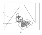
- FIG. 2 is a schematic diagram showing the action of the detection system implemented by the information processing device 200. As shown in FIG. FIG. 2 shows the action when the detection sensor 10 is an IR sensor.
- FIG. 2A is a schematic diagram showing the operation of the detection system in the initial state with no obstructions.
- FIG. 2B is a schematic diagram showing the operation of the detection system when there is an obstruction.
- FIG. 2A shows that 12 infrared rays are emitted from the detection sensor 10 toward the wall inside the environment.
- the 12 dots appearing on the wall represent the positions where the infrared rays are reflected.
- the detection range of the detection sensor 10 cannot be seen with the naked eye.
- the detection range can be represented as information on a virtual three-dimensional map by a model of 12 line segments starting from the detection sensor 10 and ending at each of the 12 points appearing on the wall.
- the detection range of the invisible sensor is visualized using the floor as a projection plane.
- the projection content conversion unit 230 performs mapping conversion for projecting information on a virtual three-dimensional map onto a projection plane. In the example shown in FIG.
- the projection content conversion unit 230 projects and converts the 12 line segments represented in three dimensions onto the floor, which is the projection plane.
- the projected sensing range in the example of FIG. 2A the 12 line segments projected onto the floor, is referred to as the "projected sensing range”.
- the projection content conversion unit 230 generates projection content expressed by projecting the projection detection range onto the projection surface of the real space using the projector 30 connected to the information processing device 200 .
- Projector 30 is preferably a short throw projector.
- An advantage of the short-focus projector is that when the projection surface is the floor, the projector 30 can be brought closer to the floor, and the projected content is less likely to be disturbed by human shadows.
- the projector 30 does not have to be installed at the same position as the detection sensor 10 .
- the projection content conversion unit 230 determines where the projector 30 is installed in the environment (hereinafter referred to as “projector position information”) and in what orientation it is installed (hereinafter “projector orientation information”), Generate projection content based on the information of
- projection detection ranges there are as many projection detection ranges as the number of detection sensors 10. For example, only one projector 30 may be prepared, and one projection content including all projection detection ranges may be projected. Also, the same number of projectors 30 as the number of detection sensors 10 may be prepared, for example, and each projector 30 may project the projection detection range of the corresponding detection sensor 10 with different projection contents. Also, the number of projectors 30 may be arbitrarily determined without depending on the number of detection sensors 10 . The number of projectors 30 may be determined in consideration of the scale of the environment and the like.
- the projected content should include additional information.
- the additional information may be, for example, the type of the detection sensor 10, the state indicating whether it is operating or sleeping, the intensity or sensitivity of the detection sensor 10, the distance from the detection sensor 10, and the like, as described above.
- the corresponding detection ranges may be color-coded depending on the type or individual difference of the detection sensors 10 .
- the projection content may be information different from the detection range. For example, if the detection sensor 10 is installed at the entrance/exit of a venue, the information different from the detection range is character information such as "closed", “exit only", "XX venue", or symbolic information such as pictograms. may be
- the setting of the projection content is specifically the color representing the detection range, the display mode, and the contents of the additional information.
- the external terminal of the information processing apparatus 200 may set items such as how to color-code the corresponding detection range according to the type or individual difference of the detection sensor 10 .
- Character information or symbol information included in the additional information may also be set by an external terminal of the information processing apparatus 200 .
- the example shown in Fig. 2 is not projection mapping because the place where the projected content is projected is the floor, which is a flat projection plane and is not three-dimensional.
- projection mapping technology may be used because the projected content is accurately aligned with the projection destination.
- the detection system according to the present disclosure does not limit the projection destination to a plane, and may perform projection mapping with the projection destination being a three-dimensional object.
- the output unit 240 outputs projection content to the projector 30 .
- the output method may be wired or wireless.
- FIG. 3 is a flow chart showing processing steps of the detection system implemented by the information processing apparatus 200 according to the first embodiment. As shown in FIG.
- the processing steps include a step in which the detection sensor 10 outputs detection range information and additional information (ST10), a step in which the receiving unit 210 receives the detection range information and additional information (ST210), A step in which the map information conversion unit 220 converts the detection range information into information on the map (ST220); a step in which the projection content conversion unit 230 converts the information on the map into projection content (ST230); It includes a step of outputting the content to projector 30 (ST240) and a step of projecting the projection content by projector 30 (ST30).
- FIG. 4 is a first schematic diagram showing an application example of the detection system according to the technology disclosed herein.
- the detection system according to the disclosed technique can be applied to a human sensor used in elevators. Since the detection range of the detection sensor 10 is visualized by the detection system according to the technology of the present disclosure, the user can use the elevator more safely.
- the detection sensor 10 is installed inside the elevator, and the projector 30 is installed outside the elevator. Therefore, the visualized detection range changes with the opening and closing of the elevator doors. Note that the installation location of the detection sensor 10 is not limited to the inside of the elevator. As shown in FIG.
- the display UI may be, for example, the detection range solidly painted with a density corresponding to the intensity or sensitivity.
- the detection system according to the technology of the present disclosure exerts a special effect during installation work and maintenance work, and is beneficial both to the installation worker who installs the detection sensor 10 and to the maintenance worker who performs maintenance. Projection of projected content can be used only during installation work and maintenance work.
- FIG. 5 is a second schematic diagram showing an application example of the detection system according to the technology disclosed herein.
- the detection system according to the technology disclosed herein can be applied to a human sensor used in an escalator.
- the detection sensor 10 is a laser sensor as shown in FIG. 5
- the display UI may be in the form of a line representing a beam of detection, for example. Since the detection range of the detection sensor 10 is visualized by the detection system according to the technology of the present disclosure, the user can use the escalator more safely.
- the detection system according to the technology disclosed herein exerts a special effect during installation work and maintenance work, and is beneficial both to the installation worker who installs the detection sensor 10 and to the maintenance worker who performs maintenance. There is no problem even if the projection of the projection content is used only during installation work and maintenance work.
- FIG. 5 shows an example of application to an escalator, it can of course also be applied to ordinary stairs.
- FIG. 6 is a schematic diagram 3 showing an application example of the detection system according to the technology disclosed herein.
- the detection system according to the technology disclosed herein can be applied to a human sensor installed in a room.
- the display UI may be in the form of a ring representing the detection range, for example.
- the display UI may have a size exceeding the projection range of the projector 30 .
- the detection system according to the disclosed technology exhibits a remarkable effect during installation work and maintenance work, and is beneficial to both the installation worker who installs the detection sensor 10 and the maintenance worker who performs maintenance. be. There is no problem even if the projection of the projection content is used only during installation work and maintenance work.
- FIG. 6 simply shows an example of application to a room, it can of course be applied to an air conditioner installed in a room and equipped with a human sensor.
- FIG. 7 is a schematic diagram 4 showing an application example of the detection system according to the technology disclosed herein.
- the detection system according to the disclosed technology can be applied to various gates.
- Various types of gates include gates at ticket gates of transportation facilities, gates at company facilities used by employees, and gates at facilities such as museums used by users.
- the gate is not limited to being made of metal, and may be made of glass, plastic, or the like that transmits the beam used for detection.
- the display UI may be selected according to the sensor information of the detection sensors 10 . Since the detection system according to the technology of the present disclosure visualizes the detection range of the detection sensor 10, the user can use the gate more safely.
- the detection system according to the technology disclosed herein exerts a special effect during installation work and maintenance work, and is beneficial both to the installation worker who installs the detection sensor 10 and to the maintenance worker who performs maintenance. There is no problem even if the projection of the projection content is used only during installation work and maintenance work.
- FIG. 8 is a schematic diagram 5 showing an application example of the detection system according to the technology disclosed herein.
- the detection system according to the disclosed technique can be applied to mobile robots such as security applications.
- the display UI may be in the form of scale lines extending in a fan shape from the detection sensor 10 .
- the detection system according to the disclosed technology is not limited to mobile robot applications, and has a special effect when collecting various data or when adjusting the parameters of the detection sensor 10 in the development stage or commercialization stage. .
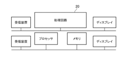
- FIG. 9 is a configuration diagram showing the hardware configuration of the information processing device 200 according to the first embodiment.
- Each function of the information processing device 200 is realized by the receiving device and the processing circuit 20 as shown in FIG.
- the receiver 210 is the receiver shown in FIG.
- Functions of the map information conversion unit 220 and the projection content conversion unit 230 are implemented by the processing circuit 20 .
- the output unit 240 is realized by an output device (not shown).
- the processing circuit 20, even if it is dedicated hardware, is also called a CPU (Central Processing Unit, central processing unit, processing unit, arithmetic unit, microprocessor, microcomputer, processor, DSP) that executes programs stored in memory. ).
- CPU Central Processing Unit
- processing circuitry 20 may be, for example, a single circuit, multiple circuits, programmed processors, parallel programmed processors, ASICs, FPGAs, or combinations thereof.
- the functions of each unit of the map information conversion unit 220 and the projection content conversion unit 230 may be realized by separate processing circuits 20, respectively, or the functions of each unit may be collectively realized by one processing circuit 20.
- the functions of the map information conversion section 220 and the projection content conversion section 230 are implemented by software, firmware, or a combination of software and firmware.
- Software and firmware are written as programs and stored in memory.
- the processing circuit 20 realizes the function of each part by reading and executing the program stored in the memory. That is, information processing apparatus 200, when executed by processing circuit 20, performs a step of receiving detection range information and additional information (ST210) and a step of converting detection range information into information on a map (ST220). , the step of converting the information on the map into projection content (ST230) and the step of outputting the projection content to the projector 30 (ST240). .
- the memory means any of non-volatile or volatile semiconductor memory such as RAM, ROM, flash memory, EPROM, EEPROM, or magnetic disk, flexible disk, optical disk, compact disk, mini disk, DVD, etc. is applicable.
- the functions of the map information conversion unit 220 and the projection content conversion unit 230 may be partly realized by dedicated hardware and partly by software or firmware.
- the function of the map information conversion unit 220 is realized by the processing circuit 20 as dedicated hardware, and the projection content conversion unit 230 is implemented by the processing circuit 20 reading and executing a program stored in the memory. It is also possible to implement functions.
- the processing circuit 20 can implement each of the above functions by hardware, software, firmware, or a combination thereof.
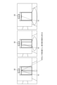
- FIG. 10 is a first reference diagram for explaining the disclosed technology.
- the projection content shows that the detection range of the detection sensor 10 is dynamically reflected. That is, FIG. 10 shows that the projected content changes moment by moment and reflects the detection result of the detection sensor 10 .
- the three pictures shown in the upper part of FIG. 10 show an example of changes in projected content when the detection sensor 10 is installed inside the glass door elevator and a sticker is attached to the glass door.
- the three pictures shown in the lower part of FIG. 10 show an example of changes in projected content when the detection sensor 10 is installed inside an elevator with a metal door and a person passes through.
- the selected display UI has the same semicircular shape. Even if the display UI selected in this way is the same, the projection content according to the technology of the present disclosure may change differently depending on the detection result of the detection sensor 10 .
- FIG. 11 is a second reference diagram for explaining the disclosed technology.
- FIG. 11 shows again that there are multiple types of display UIs that can be selected based on sensor information. It can be said that the reason why the display UI may be various is that the types of detection sensors 10 that are actually used are various and the contents to be detected are also various.
- the display UI shown in FIG. 11 is linear, fan-shaped, or semi-circular, but is not limited thereto.
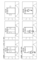
- FIG. 12 is a third reference diagram for explaining the disclosed technology.
- FIG. 12 compares changes in projection content when the detection sensor 10 is an optical range sensor and a sonic range sensor. In either case, a glass plate is placed in front of the detection sensor 10 .
- the left side of the lower part of FIG. 12 shows projected content when the detection sensor 10 is an optical distance sensor. In the case of optical distance sensors, glass panes are not detected.
- the projection content shown in the lower left part of FIG. 12 reflects the characteristics of the detection sensor 10 in this way.
- the right side of the lower part of FIG. 12 shows projected content when the detection sensor 10 is a sonic distance sensor. In the case of acoustic distance sensors, the sensing range is affected by the glass plate.
- the projection content shown on the right side of the lower part of FIG. 12 also reflects the characteristics of the detection sensor 10 .
- the detection system realized by the information processing apparatus 200 according to the first embodiment has the above configuration, the detection range of the invisible detection sensor 10 is directly displayed on the real space and visualized when necessary. is possible.
- the information processing apparatus 200 according to the technology disclosed herein provides a new concept detection system and contributes to sales promotion of products.
- a detection system realized by the information processing apparatus 200 according to the second embodiment is a system realized when the detection sensor 10 is a camera.
- the detection system according to the second embodiment can be applied to camera systems used in television stations and the like, photographing systems in concert venues, and the like.
- the reference numerals used in the second embodiment are the same as those in the first embodiment, except for intentional distinction. Further, explanations overlapping with those of the first embodiment are omitted as appropriate. Note that the term “detection" used in the second embodiment may be read as "capturing".
- Cameras are classified as sensors that have a clear detection range.
- the detection range is a three-dimensional area captured by the camera. A moving image captured by a camera is displayed in a rectangle such as a TV screen. From this, it can be said that when the detection sensor 10 is a camera, the detection range is a three-dimensional shape cut out from a quadrangular pyramid. Note that when a special lens such as a fisheye lens is used for the camera, the detection range may have another three-dimensional shape such as a cone.
- the detection sensor 10 Even if the detection sensor 10 is a camera, if a person has already been photographed, the area behind that person is not photographed.
- the detection sensor 10 is a camera, the detection range can be obtained by imagining that light is virtually emitted from the camera to form a quadrangular pyramid. When the emitted light hits the object being photographed, the area behind it becomes a shadow and the light does not reach it. Even if there is an object to be photographed, if the detection sensor 10 is a camera, the detection range is a three-dimensional shape cut out from a quadrangular pyramid.
- the detection sensor 10 is a camera of a camera system used in a television station or the like
- the sensor position information and sensor orientation information change dynamically.
- Means for periodically acquiring sensor position information and sensor orientation information may use another camera fixed in the environment, or may use a method using a landmark and a laser displacement meter.
- the sensor may be embedded in the floor surface.
- the means for acquiring the sensor position information and the sensor attitude information may use encoders on the wheels or may use GPS.
- the detection range may be estimated by an image analysis technique represented by AI, based on the content of the image captured by the camera and the image information data of the environment that has been converted into data in advance.
- the detection range may be estimated by having the camera reconstruct the 3D information through techniques of computational photography and matching it with a 3D map of the environment.
- the map information conversion unit 220 converts the detection range, which is a three-dimensional shape cut out from a quadrangular pyramid, into information on the map.
- the information on the map is the information that can be plotted on the map.
- a detection range, which is a three-dimensional shape cut out from a quadrangular pyramid, can be represented by a point group.
- a three-dimensional map defines a virtual space with a grid of points.
- a grid included in the detection range may be flagged with 1 to indicate that it is within the detection range so that the detection range can be specified.
- the additional information includes the identification number of the camera, that is, the so-called 1st camera, 2nd camera, .
- Information as to whether it is in AIR, etc. can be considered.
- the projection content conversion unit 230 converts information on the map into projection content, which is two-dimensional information that can be projected onto a projection plane that is part of the environment in association with additional information.
- the projection surface may be, for example, the floor surface in the second embodiment as well.
- the projection content conversion unit 230 projects and converts a detection range, which is a three-dimensional shape or the like cut out from a square pyramid, onto a projection plane. For example, if the detection range is represented by a point group, conversion to projection content may be achieved by projecting each point of the point group onto a projection plane.
- the detection system according to Embodiment 2 directly displays and visualizes the detection range of the invisible camera on the real space. Visualization of the detection range is realized by expressing additional information such as the ON/OFF state of the camera and the focus position of the camera. Therefore, the detection system according to the second embodiment is effective for photographers, announcers, performers, directors, producers, creators, and others.
- the mode of use of the detection system according to Embodiment 2 is effective, for example, in new employee training and rehearsals.
- the detection system according to Embodiment 2 can be applied not only to camera systems used at television stations, but also to shooting systems at concert venues. Moreover, the detection system according to the second embodiment can be applied not only to television stations but also to camera systems for general consumers.
- the information processing device 200 according to the technology disclosed herein and the detection system realized thereby can be applied to elevators, escalators, automatic doors, gates, mobile robots, camera systems, etc., and have industrial applicability.
- 1 detection system 10 detection sensor, 20 processing circuit, 30 projector, 200 information processing device, 210 reception unit, 220 map information conversion unit, 230 projection content conversion unit, 240 output unit.
Landscapes
- Engineering & Computer Science (AREA)
- Physics & Mathematics (AREA)
- General Physics & Mathematics (AREA)
- Computer Security & Cryptography (AREA)
- Manufacturing & Machinery (AREA)
- Life Sciences & Earth Sciences (AREA)
- General Life Sciences & Earth Sciences (AREA)
- Geophysics (AREA)
- Geophysics And Detection Of Objects (AREA)
- Alarm Systems (AREA)
Priority Applications (2)
| Application Number | Priority Date | Filing Date | Title |
|---|---|---|---|
| JP2022503910A JP7051031B1 (ja) | 2021-08-19 | 2021-08-19 | 情報処理装置及び検知システム |
| PCT/JP2021/030294 WO2023021639A1 (ja) | 2021-08-19 | 2021-08-19 | 情報処理装置及び検知システム |
Applications Claiming Priority (1)
| Application Number | Priority Date | Filing Date | Title |
|---|---|---|---|
| PCT/JP2021/030294 WO2023021639A1 (ja) | 2021-08-19 | 2021-08-19 | 情報処理装置及び検知システム |
Publications (1)
| Publication Number | Publication Date |
|---|---|
| WO2023021639A1 true WO2023021639A1 (ja) | 2023-02-23 |
Family
ID=81259454
Family Applications (1)
| Application Number | Title | Priority Date | Filing Date |
|---|---|---|---|
| PCT/JP2021/030294 Ceased WO2023021639A1 (ja) | 2021-08-19 | 2021-08-19 | 情報処理装置及び検知システム |
Country Status (2)
| Country | Link |
|---|---|
| JP (1) | JP7051031B1 (https=) |
| WO (1) | WO2023021639A1 (https=) |
Families Citing this family (1)
| Publication number | Priority date | Publication date | Assignee | Title |
|---|---|---|---|---|
| KR102548866B1 (ko) * | 2022-06-24 | 2023-06-29 | 주식회사 와따 | 3d 지오펜스를 이용한 위험 발생 감지 방법, 서버 및 컴퓨터프로그램 |
Citations (7)
| Publication number | Priority date | Publication date | Assignee | Title |
|---|---|---|---|---|
| JP2009010728A (ja) * | 2007-06-28 | 2009-01-15 | Olympus Corp | カメラ設置支援装置 |
| JP2009080514A (ja) * | 2007-09-25 | 2009-04-16 | Mitsubishi Electric Corp | センサ配置設計支援システム |
| US20130201292A1 (en) * | 2010-04-16 | 2013-08-08 | Otto-Von Guericke-Universitat Magdeburg | Device For Monitoring At Least One Three-Dimensional Safety Area |
| JP2015072609A (ja) * | 2013-10-03 | 2015-04-16 | アルパイン株式会社 | 電子装置、ジェスチャー入力方法、及びプログラム |
| JP2018074528A (ja) * | 2016-11-02 | 2018-05-10 | キヤノン株式会社 | 情報処理システムおよびその構成機器、実空間の監視方法 |
| JP2019010704A (ja) * | 2017-06-30 | 2019-01-24 | Idec株式会社 | 照光表示装置 |
| JP2021092442A (ja) * | 2019-12-10 | 2021-06-17 | オムロン株式会社 | 検出システム |
Family Cites Families (1)
| Publication number | Priority date | Publication date | Assignee | Title |
|---|---|---|---|---|
| WO2019176218A1 (ja) * | 2018-03-16 | 2019-09-19 | ソニー株式会社 | 情報処理装置、情報処理方法、および記録媒体 |
-
2021
- 2021-08-19 JP JP2022503910A patent/JP7051031B1/ja active Active
- 2021-08-19 WO PCT/JP2021/030294 patent/WO2023021639A1/ja not_active Ceased
Patent Citations (7)
| Publication number | Priority date | Publication date | Assignee | Title |
|---|---|---|---|---|
| JP2009010728A (ja) * | 2007-06-28 | 2009-01-15 | Olympus Corp | カメラ設置支援装置 |
| JP2009080514A (ja) * | 2007-09-25 | 2009-04-16 | Mitsubishi Electric Corp | センサ配置設計支援システム |
| US20130201292A1 (en) * | 2010-04-16 | 2013-08-08 | Otto-Von Guericke-Universitat Magdeburg | Device For Monitoring At Least One Three-Dimensional Safety Area |
| JP2015072609A (ja) * | 2013-10-03 | 2015-04-16 | アルパイン株式会社 | 電子装置、ジェスチャー入力方法、及びプログラム |
| JP2018074528A (ja) * | 2016-11-02 | 2018-05-10 | キヤノン株式会社 | 情報処理システムおよびその構成機器、実空間の監視方法 |
| JP2019010704A (ja) * | 2017-06-30 | 2019-01-24 | Idec株式会社 | 照光表示装置 |
| JP2021092442A (ja) * | 2019-12-10 | 2021-06-17 | オムロン株式会社 | 検出システム |
Also Published As
| Publication number | Publication date |
|---|---|
| JPWO2023021639A1 (https=) | 2023-02-23 |
| JP7051031B1 (ja) | 2022-04-08 |
Similar Documents
| Publication | Publication Date | Title |
|---|---|---|
| US9591267B2 (en) | Video imagery-based sensor | |
| JP7794083B2 (ja) | 情報処理装置、移動体、撮影システム、撮影制御方法およびプログラム | |
| WO2019240208A1 (ja) | ロボットおよびその制御方法、ならびにプログラム | |
| JP2020531848A (ja) | 少なくとも一つの幾何学情報を決定するためのレンジファインダ | |
| JP2020523717A (ja) | サーマルイメージングシステムにおける位置判断の装置および方法 | |
| JP2002250607A (ja) | 物体検知センサ | |
| KR100657915B1 (ko) | 코너 검출 방법 및 코너 검출 장치 | |
| JP7113375B2 (ja) | 表示装置、画像処理装置及び制御方法 | |
| WO2011054971A2 (en) | Method and system for detecting the movement of objects | |
| Koch et al. | Detection of specular reflections in range measurements for faultless robotic slam | |
| JP7051031B1 (ja) | 情報処理装置及び検知システム | |
| KR100942431B1 (ko) | 촬상소자와 광원을 이용한 터치 좌표 인식 방법 및 이를이용한 터치스크린 시스템 | |
| CN116952203A (zh) | 用于通过利用对移动对象的基于图像的干扰检测的地面扫描来进行协调测量的方法 | |
| CN105612566B (zh) | 烟雾识别设备以及用于探测至少一个烟雾探测特征的方法 | |
| JP7098081B1 (ja) | 検知システム | |
| CN116615763A (zh) | 用于确定多摄像头系统中的摄像头位姿的方法、计算机程序、机器可读介质和控制单元 | |
| JP5902006B2 (ja) | 監視カメラ | |
| JP4692437B2 (ja) | 監視カメラ装置 | |
| JP7607186B2 (ja) | 測定装置、作成装置、検査結果作成システム、およびプログラム | |
| KR101243848B1 (ko) | 무인 크레인 후크의 각도 산출 장치 | |
| Namee et al. | Compare People Counting Accuracy with OpenCV on Raspberry Pi and Infrared Sensor | |
| JPH11339150A (ja) | 画像処理を用いた火災検出装置 | |
| WO2020012906A1 (ja) | 表示装置、画像処理装置及び制御方法 | |
| WO2004057536A1 (en) | Optically triggered interactive apparatus and method of triggering said apparatus | |
| JP7369375B1 (ja) | 建築物又は土木構造物の管理支援システム |
Legal Events
| Date | Code | Title | Description |
|---|---|---|---|
| ENP | Entry into the national phase |
Ref document number: 2022503910 Country of ref document: JP Kind code of ref document: A |
|
| 121 | Ep: the epo has been informed by wipo that ep was designated in this application |
Ref document number: 21954212 Country of ref document: EP Kind code of ref document: A1 |
|
| NENP | Non-entry into the national phase |
Ref country code: DE |
|
| 122 | Ep: pct application non-entry in european phase |
Ref document number: 21954212 Country of ref document: EP Kind code of ref document: A1 |