WO2023017697A1 - 電子ペン - Google Patents
電子ペン Download PDFInfo
- Publication number
- WO2023017697A1 WO2023017697A1 PCT/JP2022/026901 JP2022026901W WO2023017697A1 WO 2023017697 A1 WO2023017697 A1 WO 2023017697A1 JP 2022026901 W JP2022026901 W JP 2022026901W WO 2023017697 A1 WO2023017697 A1 WO 2023017697A1
- Authority
- WO
- WIPO (PCT)
- Prior art keywords
- electronic pen
- push
- housing
- touch sensor
- attached
- Prior art date
- Legal status (The legal status is an assumption and is not a legal conclusion. Google has not performed a legal analysis and makes no representation as to the accuracy of the status listed.)
- Ceased
Links
Images


Classifications
-
- G—PHYSICS
- G06—COMPUTING OR CALCULATING; COUNTING
- G06F—ELECTRIC DIGITAL DATA PROCESSING
- G06F3/00—Input arrangements for transferring data to be processed into a form capable of being handled by the computer; Output arrangements for transferring data from processing unit to output unit, e.g. interface arrangements
- G06F3/01—Input arrangements or combined input and output arrangements for interaction between user and computer
- G06F3/02—Input arrangements using manually operated switches, e.g. using keyboards or dials
- G06F3/0202—Constructional details or processes of manufacture of the input device
-
- G—PHYSICS
- G06—COMPUTING OR CALCULATING; COUNTING
- G06F—ELECTRIC DIGITAL DATA PROCESSING
- G06F3/00—Input arrangements for transferring data to be processed into a form capable of being handled by the computer; Output arrangements for transferring data from processing unit to output unit, e.g. interface arrangements
- G06F3/01—Input arrangements or combined input and output arrangements for interaction between user and computer
- G06F3/03—Arrangements for converting the position or the displacement of a member into a coded form
- G06F3/033—Pointing devices displaced or positioned by the user, e.g. mice, trackballs, pens or joysticks; Accessories therefor
- G06F3/0354—Pointing devices displaced or positioned by the user, e.g. mice, trackballs, pens or joysticks; Accessories therefor with detection of two-dimensional [2D] relative movements between the device, or an operating part thereof, and a plane or surface, e.g. 2D mice, trackballs, pens or pucks
- G06F3/03545—Pens or stylus
-
- G—PHYSICS
- G06—COMPUTING OR CALCULATING; COUNTING
- G06F—ELECTRIC DIGITAL DATA PROCESSING
- G06F3/00—Input arrangements for transferring data to be processed into a form capable of being handled by the computer; Output arrangements for transferring data from processing unit to output unit, e.g. interface arrangements
- G06F3/01—Input arrangements or combined input and output arrangements for interaction between user and computer
- G06F3/03—Arrangements for converting the position or the displacement of a member into a coded form
- G06F3/033—Pointing devices displaced or positioned by the user, e.g. mice, trackballs, pens or joysticks; Accessories therefor
- G06F3/038—Control and interface arrangements therefor, e.g. drivers or device-embedded control circuitry
- G06F3/0383—Signal control means within the pointing device
-
- G—PHYSICS
- G06—COMPUTING OR CALCULATING; COUNTING
- G06F—ELECTRIC DIGITAL DATA PROCESSING
- G06F3/00—Input arrangements for transferring data to be processed into a form capable of being handled by the computer; Output arrangements for transferring data from processing unit to output unit, e.g. interface arrangements
- G06F3/01—Input arrangements or combined input and output arrangements for interaction between user and computer
- G06F3/03—Arrangements for converting the position or the displacement of a member into a coded form
- G06F3/041—Digitisers, e.g. for touch screens or touch pads, characterised by the transducing means
- G06F3/044—Digitisers, e.g. for touch screens or touch pads, characterised by the transducing means by capacitive means
- G06F3/0442—Digitisers, e.g. for touch screens or touch pads, characterised by the transducing means by capacitive means using active external devices, e.g. active pens, for transmitting changes in electrical potential to be received by the digitiser
-
- H—ELECTRICITY
- H01—ELECTRIC ELEMENTS
- H01H—ELECTRIC SWITCHES; RELAYS; SELECTORS; EMERGENCY PROTECTIVE DEVICES
- H01H9/00—Details of switching devices, not covered by groups H01H1/00 - H01H7/00
- H01H9/02—Bases, casings, or covers
Definitions
- the present invention relates to an electronic pen that enables information input by indicating coordinates to a position detection device mounted on an electronic device such as a tablet PC (Personal Computer).
- a position detection device mounted on an electronic device such as a tablet PC (Personal Computer).
- a side switch in an electronic pen means a switch provided on the side of the electronic pen so that it can be operated with a finger while holding the electronic pen.
- the side switch makes it possible to confirm a pointed position, open a window and select a function to be executed, etc., in the same way as a so-called click button of a mouse, which is a pointing device of a personal computer.
- Patent Literature 1 discloses an invention relating to a position indicator in which a side switch operating section is detachable as a unit from a body of the position indicator (electronic pen). As a result, the side switch operating portion can be attached or detached according to the frequency of use of the side switch.
- the side switch operating portion (side switch unit) is fixed to the position indicator main body by tightening screws, so it can be firmly attached, but it is difficult to attach and detach. It is time consuming and troublesome.
- the side switch unit is configured to protrude greatly from the position indicator main body in the direction crossing the axial direction. While there are users who prefer such a configuration, there are also users who want the side switch to be provided so as not to protrude from the body of the position indicator. Moreover, it would be more convenient if the side switch operation section could be easily replaced in an appropriate manner according to the type of input to be performed using the electronic pen.
- an object of the present invention is to realize an electronic pen that can flexibly change the mode of use of the side switch function according to the user's needs.
- a cylindrical housing in which an electronic pen function unit including a circuit board is mounted and a side opening for providing a side switch on the side is provided; a side attachment member attached to the side opening of the housing,
- the side mounting member has an engaging portion that engages with the housing at one end in the axial direction, and has a pressed portion at the other end,
- a pressing mechanism is provided inside the housing for pressing the pressed portion of the side attachment member attached to the side opening portion toward the one end side.
- the side mounting member is provided with an engaging portion at one end in the axial direction, and a pressed portion at the other end.
- one end side is obliquely inserted so as to abut one end side of the side opening of the housing, and the other end is inserted into the side opening of the housing.
- side is pushed down toward the side opening.
- the engaging portion at one end of the side mounting member is engaged with the inner side surface of the housing, and the pushed portion at the other end is pushed toward the one end by the pushing mechanism, thereby mounting the housing. Attached to the side opening part of the body.
- the side attachment member can be attached to the side opening of the housing by a simple operation of inserting and pushing down.
- FIG. 3 is a diagram for explaining a configuration example of a touch sensor unit according to an embodiment
- FIG. 4 is a cross-sectional view of a side switch unit and an electronic pen as side-mounted members of the embodiment; It is a figure for demonstrating the press mechanism part of the electronic pen of embodiment. It is a figure for demonstrating the example of the grip member which can be mounted
- Embodiments of the electronic pen according to the present invention will be described below with reference to the drawings.
- electronic pens such as an electromagnetic induction type (EMR (Electro Magnetic Resonance) type) electronic pen and an active capacitance type (AES (Active Electrostatic) type) electronic pen. do.
- EMR Electro Magnetic Resonance
- AES Active Electrostatic
- the present invention can be applied to any type of electronic pen as long as it is provided with a so-called side switch.
- side switch for the sake of simplification, an example of application to an electromagnetic induction type electronic pen will be described.
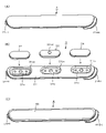
- FIG. 1 is a diagram for explaining the appearance of an electronic pen 1 and side mounting members 2, 3, and 4 according to an embodiment.
- the electronic pen 1 includes a cylindrical housing 11 that is tapered on the pen tip side and has an opening at the tip. Inside the housing 11, a core body 12 is attached to project the pen tip from an opening at the tip of the housing 11. Also, although details will be described later, a ferrite core, a coil, a writing pressure detection unit, a circuit board, and the like are mounted. An electronic pen function unit is installed to realize the electronic pen function.
- a side opening 11H is provided on the side of the housing 11 on the pen tip side, as shown in FIG. 1(A).
- a side switch unit (side switch operating portion) for pressing a switch originally provided on a circuit board mounted on the housing 11 is attached to the side opening 11H.
- a plurality of types of side attachment members can be attached to and detached from the side opening 11H of the housing 11 .
- three types of side mounting members 2, 3 and 4 are detachable.
- the side mounting member 2 shown in FIG. 1(B) functions as a lid member that closes the side opening 11H of the housing 11. As shown in FIG.
- the side mounting member 2 is hereinafter referred to as the lid member 2 .
- the cover member 2 When the cover member 2 is attached to the side opening 11H, the switch provided on the circuit board mounted inside the housing 11 cannot be operated, and the side switch function becomes unavailable. .
- the side mounting member 3 shown in FIG. 1(C) is a side switch unit consisting of one or more push-down knobs (push-down buttons) and a plate portion to which the push-down knobs are attached.
- the side mounting member 3 is hereinafter referred to as a side switch unit 3 .
- the side mounting member 4 shown in FIG. 1(D) is a touch sensor unit (touch sensor operation section) consisting of a capacitive or pressure-sensitive touch sensor and a plate section to which the touch sensor is attached.
- the side mounting member 4 is hereinafter referred to as the touch sensor unit 4 .
- the touch sensor unit 4 When the touch sensor unit 4 is attached to the side opening 11H, the switches provided on the circuit board mounted inside the housing 11 cannot be operated. Operation input through is possible.
- the three types of side mounting members 2, 3, and 4 can be easily attached to and detached from the side opening 11H of the housing 11 of the electronic pen 1.
- the user of the electronic pen 1 selects an appropriate one from the cover member 2, the side switch unit 3, and the touch sensor unit 4 in consideration of what kind of input is to be performed using the electronic pen 1. can be attached to the electronic pen 1 and used.
- FIGS. 2A, 2B, and 2C are diagrams for explaining configuration examples of the lid member 2, the side switch unit 3, and the touch sensor unit 4 as the side mounting member of the embodiment.
- the size (width, length, thickness) and outer edge shape of the lid member 2, the side switch unit 3, and the touch sensor unit 4 are all the same. It is.
- the lid member 2, the side switch unit 3, and the touch sensor unit 4 differ in whether or not they are equipped with functions, and, if they are equipped with functions, in the functions they are equipped with.
- Each of the lid member 2, the side switch unit 3, and the touch sensor unit 4 will be described below.
- FIG. 2A is a diagram for explaining a configuration example of the lid member 2.
- the cover member 2 is made of, for example, a resin material and formed in a plate shape, and is used to close the side opening 11H of the housing 11, and does not have other functions.
- the resin material constituting the lid member 2 for example, polyacetal resin (POM), polyamide resin (PA), polyethylene terephthalate resin (PET), polycarbonate resin (PC), ABS resin, etc. can be used. be.
- the lid member 2 has the same shape as the side opening 11H of the housing 11 of the electronic pen 1, and has a slightly smaller area than the side opening 11H. It is sized to fit within the opening 11H. That is, the lid member 2 is slightly shorter in width (length in the direction perpendicular to the axial direction) and overall length (length in the axial direction) than the side opening 11H. The thickness of the lid member 2 is such that the top surface of the lid member 2 substantially matches the side surface of the housing 11 when the lid member 2 is attached to the side opening 11H of the housing 11 .
- the lid member 2 is provided with a semi-cylindrical engaging portion 21FT near the bottom surface on the pen tip side so as to protrude toward the pen tip side. Further, the lid member 2 has a pressed portion 21BK on the side surface on the rear end side.
- the engaging portion 21FT of the lid member 2 is a portion that engages with the inner wall surface of the housing 11, and the pressed portion 21BK of the lid member 2 is pressed by a pressing mechanism provided inside the housing 11, which will be described later in detail. This is the portion that is pressed forward.
- the end of the pen tip side (engagement portion 21FT side) of the lid member 2 is obliquely inserted so as to abut against the pen tip side end of the side opening 11H of the housing 11, and the rear end side (cover The pressing portion 21BK side) is pushed down toward the side opening 11H, and attached to the side opening 11H.
- the lid member 2 has the engaging portion 21FT engaged with the inner wall surface of the housing 11, and the pressed portion 21BK is pushed toward the pen tip portion (one end side) by the pressing mechanism inside the housing 11. It can be attached to the side opening 11H portion of the housing 11 by being pressed.
- the pressed portion 21BK on the rear end side of the lid member 2 has a stepped shape because the pressed portion 21BK projecting toward the rear end side is pushed into the rear end side of the housing 11, The entire lid member 2 can be slidably moved to the rear end side. As a result, the engagement of the engaging portion 21FT with the inner wall surface of the housing is released so that the lid member 2 can be removed from the side opening 11H of the housing 11 . In this manner, the lid member 2 can be easily attached to the side opening 11H of the housing 11, and can be firmly maintained in the attached state. It can also be removed from the part 11H.
- FIG. 2B is a diagram for explaining a configuration example of the side switch unit 3.
- the side switch unit 3 includes a plate portion 31 and three push-down knobs (operation buttons) attached thereto, a first push-down knob 32 , a second push-down knob 33 , and a third push-down knob 34 .
- Each of the first push-down knob 32, the second push-down knob 33, and the third push-down knob 34 is made of hard rubber, for example.
- the push-down projections and mounting projections are provided on the back surfaces of the push-down knobs 32, 33, and 34, respectively, so they are not shown in FIG. 2(B).
- the surface (operation surface) of the second push-down knob 33 is provided with an operation surface projection 33TP.
- the user can confirm that the user is touching the second push-down knob 33 by touching the operation surface projection 33TP of the second push-down knob 33 with his/her finger, without looking at the side switch unit 3. , and it can be recognized that there are push-down knobs before and after it.
- the operation surface projection 33TP of the second push-down knob 33 allows the user to grasp the positions of the push-down knobs 32, 33, and 34 by touching and recognizing the side switch unit 3 without looking at the side switch unit 3. I have to.
- the plate portion 31 is formed using a metal material or various resin materials as in the case of the lid member 2 described above.
- the plate portion 31 includes a first mounting portion 31a to which the first push-down knob 32 is mounted, a second mounting portion 31b to which the second push-down knob 33 is mounted, and a third mounting portion 31c to which the third push-down knob 34 is mounted.
- a first mounting portion 31a to which the first push-down knob 32 is mounted a second mounting portion 31b to which the second push-down knob 33 is mounted
- a third mounting portion 31c to which the third push-down knob 34 is mounted.
- Each of the first mounting portion 31a, the second mounting portion 31b, and the third mounting portion 31c has, as shown in FIG. Small mounting holes are provided on the front and rear of the knob, into which mounting projections of corresponding push-down knobs are fitted.
- Each of the first mounting portion 31a, the second mounting portion 31b, and the third mounting portion 31c has a substantially rectangular shape.
- the plate portion It does not protrude from the upper surface of 31.
- the first mounting part 31a is connected to the plate part 31 through the first support part 31ax on the rear end side (the right side in FIG. 2(B)), and the other parts are not in contact with the plate part 31.
- the second mounting portion 31b is connected to the plate portion 31 through the second support portion 31bx on the rear end side, and the other portions are not in contact with the plate portion 31.
- the third mounting portion 31c is connected to the plate portion 31 through the third support portion 31cx on the rear end side, and the other portions are not in contact with the plate portion 31. As shown in FIG.
- the plate portion 31 shown in FIG. 2B has the same shape as the side opening 11H of the housing 11 of the electronic pen 1, similarly to the lid member 2 shown in FIG.
- the area is slightly smaller than that, and is sized to fit within the side opening 11H. That is, the plate portion 31 is slightly shorter in width and overall length than the side opening 11H.
- the thickness of the plate portion 31 is such that when the plate portion 31 is attached to the side opening portion 11H of the housing 11, the top surface of the plate portion 31 substantially matches the side surface of the housing 11. It has become.
- the plate portion 31 shown in FIG. 2B also has a semi-cylindrical engagement portion near the bottom surface of the pen tip so as to protrude toward the pen tip. It has a junction 31FT. Further, the plate portion 31 has a pressed portion 31BK on the side surface on the rear end side.
- the engaging portion 31FT of the plate portion 31 is a portion that engages with the inner wall surface of the housing 11, and the pressed portion 31BK of the plate portion 31 is pressed by a pressing mechanism provided in the housing 11, which will be described later in detail. This is the portion that is pressed forward.
- the side switch unit 3 formed by attaching the first push-down knob 32, the second push-down knob 33, and the third push-down knob 34 to the plate portion 31 is attached to the side opening 11H portion of the housing 11.
- the pen tip side (engagement portion 31FT side) of the side switch unit 3 is obliquely inserted so as to abut against the end side of the pen tip side of the side opening 11H of the housing 11, and the rear end side (pressed 31BK side) is pushed down toward the side opening 11H.
- the engaging portion 31FT of the side switch unit 3 is engaged with the inner wall surface of the housing 11, and the pressed portion 31BK is pressed toward the pen tip by the pressing mechanism inside the housing 11. can be attached to the side opening 11H portion of the
- the pushed portion 31BK projecting toward the rear end side is pushed toward the rear end side of the housing 11, whereby the side switch unit 3 as a whole moves backward.
- the engagement of the engaging portion 31FT can be released by slidably moving to the end side.
- the side switch unit 3 is not only easily attached to the side opening 11H of the housing 11, but also can be easily removed from the side opening 11H of the housing 11 as required. .
- FIG. 2C is a diagram for explaining a configuration example of the touch sensor unit 4.
- the touch sensor unit 4 is formed, for example, by providing a touch sensor section 42 on a plate section 41 made of various resins.
- the touch sensor section 42 is formed by covering a sheet-shaped touch sensor with an elastomer, as will be described later in detail.
- the plate portion 41 can be formed using various resins in the same manner as the lid member 2 described above.
- the touch sensor unit 4 also has the same shape and size as the lid member 2 shown in FIG. 2(A). Further, the plate portion 41 of the touch sensor unit 4 is provided with a semi-cylindrical engaging portion 41FT near the bottom surface on the pen tip side so as to protrude toward the pen tip side. Further, the plate portion 41 has a side surface on the rear end side that is a pressed portion 41BK.
- the engaging portion 41FT of the touch sensor unit 4 is a portion that engages with the inner wall surface of the housing 11, and the pressed portion 41BK of the touch sensor unit 4 is a pressing mechanism provided inside the housing 11, which will be described later in detail. This is the portion that is pressed toward the pen tip side by These points are also the same as those of the lid member 2 described above.
- the pen tip side (engaging portion 41FT side) of the touch sensor unit 4 is obliquely inserted so as to abut against the pen tip side end side of the side opening 11H of the housing 11, and the rear end side (pressed 41BK side) is pushed down toward the side opening 11H.
- the engaging portion 21FT of the touch sensor unit 4 is engaged with the inner wall surface of the housing 11, and the pressed portion 21BK is pressed toward the pen tip by the pressing mechanism inside the housing 11. can be attached to the side opening 11H portion of the
- the touch sensor unit 4 as in the case of the cover member 2, the pressed portion 41BK projecting toward the rear end side is pushed toward the rear end side of the housing 11, thereby completely covering the touch sensor unit 4.
- the engagement of the engaging portion 41FT can be released by sliding it to the rear end side.
- the touch sensor unit 4 can be easily attached to the side opening 11H portion of the housing 11, and can also be easily removed from the side opening 11H portion of the housing 11 as necessary. .
- FIG. 3 is a diagram for explaining a configuration example of the touch sensor unit 4 according to the embodiment.
- 3A is a cross-sectional view of the touch sensor unit 4
- FIG. 3B is a cross-sectional view of the touch sensor section 42 of the touch sensor unit 4.
- FIGS. 3C and 3D are diagrams showing examples of arrangement of touch sensors of different types with different detection methods.
- the two types of touch sensors with different detection methods are a pressure-sensitive (resistive film) sensor and a capacitive sensor.
- connection terminal 42T is led out from the touch sensor section 42, and is provided on a circuit board mounted in the housing 11 when the touch sensor unit 4 is attached to the side opening 11H portion of the housing 11. It is designed to be connected to a connection terminal. Thereby, the detection output from the touch sensor section 42 can be supplied to the circuit board.
- the touch sensor unit 42 is configured by stacking substrate Bd1 ⁇ pressure-sensitive sensors CH5 and CH6 ⁇ substrate Bd2 ⁇ capacitive sensors CH1, CH2, CH3, and CH4 in this order from the bottom (plate portion 41 side).
- Capacitive sensors CH1, CH2, CH3, and CH4 are arranged on a substrate Bd2 that is in the same plane as shown in FIG. 3(B). That is, as shown in FIGS. 3B and 3C, the capacitive sensors CH1, CH2, CH3, and CH4 are arranged in the axial direction of the electronic pen (the direction indicated by the arrow Ar in FIG. It is an array.
- Capacitive sensors CH1, CH2, CH3, and CH4 are capable of detecting changes in capacitance between fingertips and conductive films to detect whether or not they have been operated. It is possible to detect it by itself.
- the pressure-sensitive sensors CH5 and CH6 are arranged in a direction that intersects the axial direction of the electronic pen (direction indicated by arrow Cr in FIG. 3(D)). Since FIG. 3B is a cross-sectional view when viewed from the front side of FIG. It does not appear in (B).
- the pressure-sensitive sensor CH5 is configured by bonding a first electrode FE1 and a second electrode FE2 with an adhesive layer Ads.
- a voltage is applied to one of two opposing electrodes (resistive films). It is possible to detect whether or not the button has been pressed by generating a voltage. Therefore, unlike the capacitive sensors CH1, CH2, CH3, and CH4, the pressure-sensitive sensor CH5 does not generate a voltage just by bringing a fingertip close to it, and does not produce a detection output unless a certain amount of pressure is applied. It is.
- the pressure-sensitive sensor CH6 is also constructed in the same manner as the pressure-sensitive sensor CH5.
- the capacitive sensors CH1, CH2, CH3, and CH4 are capable of detecting when the user's fingertips come close to a certain distance.
- the pressure-sensitive sensors CH5 and CH6 cannot detect that they are being operated unless they are pressed with a certain amount of force.
- substrate Bd1 ⁇ pressure-sensitive sensors CH5 and CH6 ⁇ substrate Bd2 ⁇ capacitive sensors CH1, CH2, CH3, and CH4 are laminated in this order.
- the touch sensor unit 42 (FIG. 3(B)) is configured as a result.
- the operation is only detected by the capacitive sensors CH1, CH2, CH3, and CH4.
- a pressing operation is performed so as to apply pressure equal to or greater than a predetermined value on the touch sensor section 42 .
- the capacitance sensors CH1, CH2, CH3, and CH4 the capacitance sensors corresponding to the depressed portions and the pressure-sensitive sensors CH5 and CH6 located below them are simultaneously pressed. can be detected.
- the touch sensor unit 4 can accept slide operation input for which only the capacitive sensors CH1, CH2, CH3, and CH4 of the touch sensor section 42 function. Also, the touch sensor unit 4 can accept a press operation input in which both the capacitive sensors CH1, CH2, CH3, CH4 and the pressure-sensitive sensors CH5, CH6 function simultaneously. Also, by considering the position of the sensor that detects the operation input, it is possible to receive a plurality of different types of operation input.
- the electronic pen 1 of this embodiment can be used by freely replacing the lid member 2, the side switch unit 3, and the touch sensor unit 4. Therefore, the user can attach the lid member 2 to the electronic pen 1 and disable the side switch function when, for example, handwriting character input is performed. Further, for example, when creating an image using CG technology, the side switch unit 3 is attached to the electronic pen 1, and the side switch function is frequently used, the airbrush function is used, line type, color, etc. are used. can be freely drawn by frequently changing the Further, for example, when editing a sentence, the touch sensor unit 4 is attached to the electronic pen 1, and while the screen is freely scrolled, cutting out, moving, adding a document, etc. are performed, and the editing work is performed. can be done smoothly.
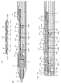
- FIG. 4 is a cross-sectional view of the side switch unit 3 and the electronic pen 1 as side mounting members of the embodiment.
- FIG. 4A is a cross-sectional view of the side switch unit 3 cut in half along the axial direction.
- the side switch unit 3 includes a plate portion 31, a first push-down knob 32, a second push-down knob 33, and a third push-down knob .
- the plate portion 31 includes a first mounting portion 31a, a second mounting portion 31b, and a third mounting portion 31c, as shown in FIG. 2B.
- the first pressing knob 32 is attached to the first attaching portion 31a
- the second pressing knob 33 is attached to the second attaching portion 31b
- the third pressing knob 34 is attached to the third attaching portion 31c.
- the side switch unit 3 is configured.
- each of the first to third push-down knobs 32, 33, and 34 has a push-down projection in the central portion of the lower surface and mounting projections in front and behind the corresponding first to third attachment points. It is mounted by being fitted into the push-down projection holes of the portions 31a, 31b, and 31c and the mounting holes in front and behind thereof.
- the first mounting portion 31a is connected to the plate portion 31 by the first support portion 31ax, and the other portion is not connected to the plate portion 31.
- the second mounting portion 31b is connected to the plate portion 31 by the second support portion 31bx, and is not connected to the plate portion 31 at other portions.
- the third mounting portion 31c is connected to the plate portion 31 by the third support portion 31cx, and is not connected to the plate portion 31 at other portions.
- the thickness of the first push-down knob 32 is thinner than the thicknesses of the second push-down knob 33 and the third push-down knob 34 .
- the operation surface projection 33TP is provided on the surface of the operation portion of the second push-down knob 33 .
- the thickness of these push-down knobs 32, 33, and 34 and the operation surface projection 33TP of the second push-down knob 33 allow the user to recognize which push-down knob his or her finger is touching. As a result, the user can appropriately press down the desired push-down knobs 32 , 33 , 34 without looking at the side switch unit 3 .
- the push knobs 32, 33, and 34 may all have different thicknesses, or may all have the same thickness.
- a metal plate (metal piece) 35 is fixed between the second mounting portion 31b and the third mounting portion 31c.
- the metal plate 35 together with a magnet provided inside the housing 11, which will be described later, holds the side switch unit in an appropriate position with respect to the housing 11 when the side switch unit 3 is attached to the side opening 11H portion of the housing 11. It functions as a positioning part that enables the attachment of 3.
- the metal plate 35 also functions as a holding portion that prevents the side switch unit 3 from easily coming off from the side opening 11H of the housing 11, together with a magnet provided inside the housing 11, which will be described later.
- FIG. 4B is a cross-sectional view of the electronic pen 1 when the side switch unit 3 is not attached to the side opening 11H of the housing 11, and the electronic pen 1 is axially aligned.
- 2 is a cross-sectional view of a portion from the pen tip to the vicinity of the central portion of the electronic pen 1 when cut in half.
- FIG. 4B includes the entire side opening 11H from the tip of the pen, but the rear end portion is omitted.
- the electronic pen function unit is mounted inside the housing 11 .
- the core 12 is inserted from the rear end of the core 12 through the tapered opening of the pen tip side of the housing 11 to form a pipe-shaped ferrite core. 13 to be attached to the writing pressure detection unit 15 .
- a coil 14 that forms a resonance circuit together with a capacitor mounted on a circuit board 17 (to be described later) is wound around the side surface of the ferrite core 13 .
- the core body 12 protrudes the pen tip from the opening at the tip of the tapered portion of the housing 11, and the core body 12 slides in the axial direction according to the writing pressure applied to the pen tip. It's becoming That is, the core body 12 is pushed into the housing 11 and moves toward the writing pressure detection unit 15 when the writing pressure is applied, and is pushed back to the original position when the writing pressure is released.
- the writing pressure detection unit 15 is configured as a variable capacitor, and detects the writing pressure according to the capacitance that changes according to the writing pressure applied to the core 12 .
- a circuit board 17 on which various circuit components such as push-down switches SW1, SW2, and SW3 that realize the side switch function, a capacitor, and a control IC are mounted is provided behind the writing pressure detection unit 15 .
- the circuit board 17 is placed on a half-pipe-shaped board holding member 16 whose upper side, which is the circuit board 17 side, is open, and is fixed in position within the housing 11 . That is, the substrate holding member 16 is fixed inside the housing 11 .
- an inverted half-pipe-shaped board protection member 18 with an opening on the lower side, which is on the side of the circuit board 17, is provided. You can't touch it.
- the board protection member 18 is provided with a first pressing portion 18a at a portion facing the first mounting portion 31a of the plate portion 31 of the side switch unit 3 when the side switch unit 3 is mounted in the side opening portion 11H. ing.
- a second pressing portion 18b is provided in the portion of the board protection member 18 that faces the second mounting portion 31b of the plate portion 31, and the board protection member 18 faces the third mounting portion 31c of the plate portion 31.
- a portion 18 is provided with a third pressing portion 18c.
- a pressing protrusion is provided on the lower side of the first pressing portion 18a so that the switch SW1 of the circuit board 17 can be pressed by this protrusion.
- a pressing projection is provided on the lower side of the second pressing portion 18b so that the switch SW2 on the circuit board 17 can be pressed.
- a pressing projection is provided on the lower side of the third pressing portion 18c so that the switch SW3 on the circuit board 17 can be pressed.
- first pressing portion 18a of the substrate protection member 18 is connected to the substrate protection member 18 through the first support portion 18ax, and the other portion is not connected to the substrate protection member 18.
- second pressing portion 18b of the substrate protection member 18 is connected to the substrate protection member 18 through the second support portion 18bx, and is not connected to the substrate protection member 18 at other portions.
- third pressing portion 18c is connected to the substrate protection member 18 through the third support portion 18cx, and is not connected to the substrate protection member 18 at other portions.
- a magnet 19 is fixed at a position on the pen tip side of the third support portion 18cx.
- the magnet 19 attracts the metal plate 35 of the side switch unit 3, functions as a positioning portion for the side switch unit 3, and also functions as a holding portion for holding the side switch unit 3 in the side opening portion 11H.
- a pressing mechanism 70 is provided on the top surface of the substrate protection member 18 on the rear end side.
- the pressing mechanism portion 70 includes a pressing member 71 and a coil spring 72 that is an elastic member.
- the pressing member 71 is positionally regulated so as not to protrude toward the tip of the pen more than necessary or be pushed toward the rear end more than necessary.
- the pressing member 71 is always urged toward the pen tip side by a coil spring 72, but when it is pushed toward the rear end side, the coil spring 72 shrinks so that it can slide toward the rear end side. It has become.
- FIG. 5 is a diagram for explaining the pressing mechanism section 70 of the electronic pen according to the embodiment.
- a rear end portion of the substrate protection member 18 serves as a mounting recess in which the pressing member 71 and the coil spring 72 are mounted.
- the pressing member 71 includes a pressing plate portion 71a, which is a plate-like body having an arc-shaped concave portion on the tip surface so as to match the pressed portion 31BK on the rear end side of the side switch unit 3, and a pressing plate portion 71a. and a rod-shaped portion 71b extending from the center of the end face toward the rear end side.
- a coil spring 72 is wound around the bar-shaped portion 71b.
- Recesses 71L and 71R are provided on the left and right side surfaces of the pressing plate portion 71a. Further, when the pressing member 71 is placed in the mounting recess of the substrate protection member 18, the left and right recesses of the substrate protection member 18 are placed at the positions corresponding to the left and right recesses 71L and 71R of the pressing plate portion 71a. Protrusions 18L and 18R projecting from the inner surface are provided. The pressing member 71 and the coil spring 72 are mounted in the mounting recess of the board protection member 18 as shown in FIG.
- the pressing member 71 is mounted in the mounting recess of the substrate protection member 18 so that the rear end side of the bar-shaped portion 71b around which the coil spring 72 is wound is hidden behind the arch portion 18AH at the rear end of the substrate protection member 18. be.
- the convex portion 18L protruding from the left inner side surface of the mounting concave portion of the substrate protection member 18 enters into the concave portion 71L on the left side surface of the pressing plate portion 71a, and the concave portion 71R on the right side surface of the pressing plate portion 71a
- a protrusion 18L protruding from the right inner side surface of the mounting recess of the substrate protection member 18 enters.
- the pressing member 71 and the coil spring 72 are mounted on the mounting recess on the rear end side of the board protection member 18 so as not to come off or shift.
- the axial lengths of the concave portions 71L and 71R of the pressing plate portion 71a are longer than the axial lengths of the convex portions 18L and 18R of the board protection member 18 .
- the length (depth of the recess) of the recesses 71L and 71R of the pressing plate portion 71a in the direction intersecting the axial direction is the length of the projections 18L and 18R of the substrate protection member 18 in the direction intersecting the axial direction. It is slightly longer (deeper) than the height (the length of the overhang of the convex portion) or approximately the same length.
- the pressing member 71 can slide in the axial direction within a range restricted by the left and right protrusions 18L and 18R of the substrate protection member 18. As shown in FIG. That is, the pressing member 71 is prevented from protruding more than necessary toward the tip of the pen or entering toward the rear end more than necessary.
- the rod-shaped portion 71b of the pressing member 71 is provided with a coil spring 72 so as to be wound thereon, and this is attached to the rear end surface of the pressing plate portion 71a and the rear end inner wall surface of the mounting recess of the substrate protection member 18.
- the pressing plate portion 71a is urged toward the pen tip side at all times. However, if the pressing plate portion 71a is pushed rearward, the coil spring 72 is contracted and can be slid to the rear end side within the range restricted by the convex portions 18L and 18R of the substrate protection member 18.
- the side switch unit 3 when the side switch unit 3 is attached, the side switch unit 3 can be firmly attached to the side opening 11H portion of the housing 11 by the action of the pressing mechanism 70 and maintained in that state. However, it is also possible to slide the pressing member 71 by pushing it toward the rear end side, so that the side switch unit 3 can be easily removed.
- FIG. 4C is a cross-sectional view of the electronic pen 1 when the side switch unit 3 is attached to the side opening 11H portion of the housing 11, and the electronic pen 1 is cut in half along the axial direction. It is an enlarged view centering on the side opening 11H portion when cut.
- the pen point side of the side switch unit 3 shown in FIG. 4A is tilted downward, and the engaging portion 31FT is inserted into the gap gp between the board protection member 18 and the housing 11 shown in FIG. 4B. , and push the rear end of the side switch unit 3 toward the side opening 11H.
- the side switch unit 3 can be attached to the side opening 11H of the housing 11 of the electronic pen 1, as shown in FIG. 4(C).
- the engaging portion 31FT of the side switch unit 3 engages with the inner wall surface of the housing 11 on the pen tip side of the side opening 11H. Further, the pressed portion 31BK at the rear end of the side switch unit 3 is pressed toward the pen tip by the pressing member 71 of the pressing mechanism portion 70 provided on the rear end side of the board protection member 18 . Furthermore, the metal plate 35 of the side switch unit 3 is attracted to the magnet 19 of the board protection member 18 .
- the side switch unit 3 can be attached to the proper position of the side opening 11H portion of the housing 11 of the electronic pen 1, and can be prevented from being easily removed due to the confusion of these three functions.
- the user touches the upper surface of the side switch unit 3 with his finger and touches the rear end side of the electronic pen 1. to push up.
- the side switch unit 3 is slid to the rear end side of the electronic pen 1 .
- the side switch unit 3 is slidably moved to the rear end side of the electronic pen 1 together with the pressing member 71 of the pressing mechanism section 70, and the inner side of the housing 11 at the pen tip side end portion of the side opening 11H.
- the engagement between the wall surface and the engagement portion 31FT on the pen point side of the side switch unit 3 is released.
- the pen tip side of the side switch unit 3 can be separated from the housing 11 of the electronic pen 1, so the pen tip side of the side switch unit 3 is lifted.
- the metal plate 35 of the side switch unit 3 is separated from the magnet 19 of the board protection member 18, and the pressing of the pressing member 71 of the pressing mechanism 70 to the pressed portion 31BK of the side switch unit 3 is released. .
- the side switch unit 3 can be easily removed from the side opening 11H.
- the side switch unit 3 is attached to and detached from the side opening 11H portion of the housing 11 of the electronic pen 1 . It can be put on and taken off in the same way. That is, when mounting, the cover member 2 and the touch sensor unit 4 are tilted with the pen tip side inclined so that the space gp between the board protection member 18 and the housing 11 shown in FIG. Insert joints 21FT and 41FT. Further, the lid member 2 and the rear end portions of the touch sensor unit 4 are pushed toward the side opening portion 11H. As a result, the lid member 2 and the touch sensor unit 4 can be easily attached to the side opening 11H of the housing 11 .
- the lid member 2 and the touch sensor unit 4 When removing, the lid member 2 and the touch sensor unit 4 are pushed up toward the rear end side of the electronic pen 1 and slidably moved to engage the inner wall surface of the housing 11 and the engaging portions 21FT and 41FT. remove the joint. After that, if the pen tip side of the cover member 2 and the touch sensor unit 4 is lifted, the pressed portions 21BK and 41BK of the cover member 2 and the touch sensor unit 4 are also pressed by the pressing member 71 of the pressing mechanism 70. be released. As a result, the lid member 2 and the touch sensor unit 4 can be easily removed from the side opening 11H.
- the lid member 2 and the touch sensor unit 4 may also be provided with metal plates (metal pieces) at the same positions as the metal plate 35 of the side switch unit 3 .
- the metal plate is attracted by the magnet 19 of the substrate protection member 18, and the cover member 2 and the touch sensor unit 4 are attached to appropriate positions, and easily removed from the side opening 11H portion of the housing 11. You can make sure it doesn't happen.
- the electronic pen 1 of this embodiment has a thin shaft as a whole. For this reason, some users may wish to make the shaft portion of the electronic pen 1 that they hold in their hand thicker. Therefore, it is considered that the electronic pen 1 is equipped with a post-installed grip member that thickens the shaft portion. In this case, the mounting of the side mounting member such as the side switch unit becomes a problem. In other words, if only the side opening is provided in the retrofitted grip member, the thickness of the grip member becomes an obstacle and the side switch function cannot be properly used. Therefore, a side mounting member such as a side switch unit corresponding to the retrofitted grip member can be used.
- FIG. 6 is a diagram for explaining an example of the grip member 5 that can be attached to the electronic pen 1 of the embodiment and the side attachment member 6 that can be used when the grip member 5 is attached to the electronic pen 1.
- the side mounting member 6 shown in FIG. 6 is an example of a side switch unit.
- the retrofitted grip member 5 is a cylindrical body with openings at the front end surface and the rear end surface.
- a side opening 5H is provided to match the side opening 11H of the body 11.
- the thickness of the grip member 5 in the direction orthogonal to the axial direction is a thickness h1 as shown in FIG. 6A, and the shaft portion of the electronic pen 1 can be thickened by this thickness h1.
- the side switch unit 6 used together with the grip member 5 is similar to that of the side switch unit 3 described with reference to FIGS. 2(B) and 4(A). Therefore, the side switch unit 6 comprises a plate portion 61, a first push-down knob 62, a second push-down knob 63, and a third push-down knob 64, as shown in FIG. 6(B).
- An engaging portion 61FT corresponding to the engaging portion 31FT of the side switch unit 3 is provided on the bottom side of the front end surface of the side switch unit 6, and the bottom side of the rear end surface is covered by the side switch unit 3.
- the pressed portion 61BK corresponds to the pressed portion 31BK.
- the thickness of the plate portion 61 (the thickness in the direction intersecting the axial direction) is the thickness h2 that is the sum of the thickness of the housing 11 of the electronic pen 1 and the thickness h1 of the grip member 5 .
- the plate portion 61 of this example also has the same configuration as the plate portion 31 shown in FIG. 2(B). That is, although not shown, it has a first mounting portion 61a, a second mounting portion 61b, and a third mounting portion 61c. Also in this example, the first mounting portion 61a is connected to the plate portion 61 by the first support portion 61ax, the second mounting portion 61b is connected to the plate portion 61 by the second support portion 61bx, and the third mounting portion 61c is connected to the plate portion 61 by the second support portion 61bx. It is connected to the plate portion 61 by 3 support portions 61cx.
- Each of the first mounting portion 61a, the second mounting portion 61b, and the third mounting portion 61c is attached to the plate portion 61 except for the portions connected by the first support portion 61ax, the second support portion 61bx, and the third support portion 61cx. is not connected.
- the thicknesses of the first mounting portion 61a, the second mounting portion 61b, and the third mounting portion 61c are basically the same as those of the first mounting portion 31a, the second mounting portion 31b, and the third mounting portion shown in FIG. 31c.
- the push-down protrusions provided in the central portion of the lower surface of the first push-down knob 62, the second push-down knob 63, and the third push-down knob 64 have a length corresponding to the thickness h2 of the plate portion 61.
- the push-down knobs provided at the center of the lower surface of the first push-down knob 62, the second push-down knob 63, and the third push-down knob 64 of the side switch unit 6 are designed to protect the substrate in the manner shown in FIG. 4(C). It contacts central portions of the first pressing portion 18a, the second pressing portion 18b, and the third pressing portion 18c of the member.
- the grip member 5 is not limited to the one shown in FIG. 5, and grip members with various designs that can be attached to the shaft of the electronic pen 1 can be used.
- the grip member 5 may be formed using various elastomers, which are polymeric materials having elasticity, such as natural rubber and synthetic rubber, or may be formed using various materials such as metal, wood, and hard resin. You can
- the side switch unit 6 is used as the side mounting member has been described here as an example.
- the lid member and the touch sensor unit can also be configured to have an increased thickness in the direction intersecting the axial direction.
- a cover member and a touch sensor unit corresponding to the grip member 5 attached later can be configured.
- the side switch function can be disabled in the same manner as when the cover member 2 is attached.
- the mode of use of the side switch function can be flexibly changed in the same manner as when the grip member 5 is not attached. be able to.
- the side switch unit 3 is provided with the three push-down knobs 32, 33, 34, and the side switch unit is provided with the three push-down knobs 62, 63, 64.
- the number of push-down knobs of the side switch unit such as a side switch unit having two push-down knobs or a side switch unit having one push-down knob, can be set appropriately within an operable range.
- the circuit board 17 of the electronic pen 1 may be provided with switches corresponding to the number of push-down knobs of the side switch unit. Two or any one may be used.
- the touch sensor unit 4 it is possible to use only a capacitive touch sensor or only a pressure sensitive touch sensor. Also, in this case, the arrangement of the touch sensors can be various arrangements. Of course, even when a capacitive touch sensor and a pressure-sensitive touch sensor are used, various arrangements and stacking orders can be used.
- the lid member, the side switch units 3 and 6, and the touch sensor unit 4 can have various sizes according to the size of the side opening 11H provided in the housing 11 of the electronic pen 1.
- the operation surface projection 33TP is provided on the operation surface of the second push-down knob 33, but the present invention is not limited to this.
- the operation surface projection 33TP can be omitted, or can be provided on the operation surface of another push-down knob.
- the side switch unit 3 is provided with the metal plate 35, and the board protection member 18 is provided with the magnet 19 at the corresponding position.
- the side switch unit 3 may be provided with a plurality of metal plates, and the board protection member 18 may also be provided with magnets at positions corresponding to the plurality of metal plates of the side switch unit 3 .
- the plate portions 31, 61 of the side switch units 3, 6 can be made of various metal materials, the weight can be changed according to the type of metal material. As a result, when it is desired to realize a so-called electronic pen 1 with a low center of gravity, the side switch unit 3 in which the plate portion 31 is formed using a heavy metal material can be used. Further, when an electronic pen that is light overall is realized, it is possible to use the side switch unit 3 in which the plate portion 31 is formed using a light metal material.
- the side mounting members such as the lid member 2, the side switch unit 3, and the touch sensor unit 4 can be freely, easily, and appropriately attached and detached, new functions can be added using this.
- the electronic pen 1 is of the active capacitive type, power is required to drive the oscillator in order to send out signals from the core.
- a charging terminal that can be connected when the side mounting member is removed to expose the inside of the housing 11 is provided, and the charging terminal is passed through the charging terminal. Battery charging can be enabled.
- the engaging portion 31FT is provided at the end on the pen tip side, and the pressed portion 31BK is provided on the rear end side.
- the end of the side switch unit 3 on the side of the pen tip may be used as the pressed portion, and the engaging portion may be provided on the end on the rear end side.
- a pressing mechanism 70 may be provided on the pen tip side of the board protection member 18 to press the side mounting member from the pen tip side toward the rear end side.
- the lid member 2, the touch sensor unit 4, and the side switch unit 6 can also have the same configuration.
Landscapes
- Engineering & Computer Science (AREA)
- General Engineering & Computer Science (AREA)
- Theoretical Computer Science (AREA)
- Human Computer Interaction (AREA)
- Physics & Mathematics (AREA)
- General Physics & Mathematics (AREA)
- Position Input By Displaying (AREA)
Priority Applications (4)
| Application Number | Priority Date | Filing Date | Title |
|---|---|---|---|
| CN202280042981.9A CN117501215A (zh) | 2021-08-13 | 2022-07-07 | 电子笔 |
| JP2023541241A JPWO2023017697A1 (https=) | 2021-08-13 | 2022-07-07 | |
| US18/434,421 US12321538B2 (en) | 2021-08-13 | 2024-02-06 | Electronic pen |
| US19/204,336 US20250271949A1 (en) | 2021-08-13 | 2025-05-09 | Electronic pen |
Applications Claiming Priority (2)
| Application Number | Priority Date | Filing Date | Title |
|---|---|---|---|
| JP2021131919 | 2021-08-13 | ||
| JP2021-131919 | 2021-08-13 |
Related Child Applications (1)
| Application Number | Title | Priority Date | Filing Date |
|---|---|---|---|
| US18/434,421 Continuation US12321538B2 (en) | 2021-08-13 | 2024-02-06 | Electronic pen |
Publications (1)
| Publication Number | Publication Date |
|---|---|
| WO2023017697A1 true WO2023017697A1 (ja) | 2023-02-16 |
Family
ID=85199941
Family Applications (1)
| Application Number | Title | Priority Date | Filing Date |
|---|---|---|---|
| PCT/JP2022/026901 Ceased WO2023017697A1 (ja) | 2021-08-13 | 2022-07-07 | 電子ペン |
Country Status (4)
| Country | Link |
|---|---|
| US (2) | US12321538B2 (https=) |
| JP (1) | JPWO2023017697A1 (https=) |
| CN (1) | CN117501215A (https=) |
| WO (1) | WO2023017697A1 (https=) |
Citations (6)
| Publication number | Priority date | Publication date | Assignee | Title |
|---|---|---|---|---|
| JPH0512939U (ja) * | 1991-07-19 | 1993-02-19 | 株式会社ワコム | スタイラスペン用サイドスイツチノブ、ノブストツパおよびそれまたはそれらを備えたスタイラスペン |
| JPH0887368A (ja) * | 1994-09-19 | 1996-04-02 | Japan Aviation Electron Ind Ltd | ペン入力装置用センサ及びペン入力装置 |
| JPH0895696A (ja) * | 1994-09-29 | 1996-04-12 | Pentel Kk | サイドスイッチ付き入力ペン |
| JPH096518A (ja) * | 1995-06-16 | 1997-01-10 | Wacom Co Ltd | サイドスイッチ機構及びスタイラスペン |
| JP2013045206A (ja) * | 2011-08-23 | 2013-03-04 | Seiko Epson Corp | 電子ペン |
| JP2020024660A (ja) * | 2018-08-07 | 2020-02-13 | 深▲セン▼普贏創新科技股▲分▼有限公司 | 側圧式ポインティングデバイス |
Family Cites Families (38)
| Publication number | Priority date | Publication date | Assignee | Title |
|---|---|---|---|---|
| JPH04349316A (ja) * | 1991-05-24 | 1992-12-03 | Matsushita Electric Ind Co Ltd | 電子機器用防水スイッチ |
| JP3849995B2 (ja) | 1997-04-28 | 2006-11-22 | 株式会社ワコム | 位置指示器 |
| FR2832230B1 (fr) * | 2001-11-13 | 2004-01-30 | France Telecom | Style pour ordinateur et ordinateur destine a etre utilise avec un tel stylet |
| US6727439B2 (en) * | 2002-01-28 | 2004-04-27 | Aiptek International Inc. | Pressure sensitive pen |
| US9389707B2 (en) * | 2011-10-28 | 2016-07-12 | Atmel Corporation | Active stylus with configurable touch sensor |
| US11347330B2 (en) * | 2011-10-28 | 2022-05-31 | Wacom Co., Ltd. | Adaptive transmit voltage in active stylus |
| CN203338261U (zh) * | 2013-05-31 | 2013-12-11 | 梁徽湖 | 具有防水功能的触控笔 |
| US9691570B1 (en) * | 2013-10-28 | 2017-06-27 | Apple Inc. | Modular tactile switch |
| EP3106966B1 (en) * | 2014-02-12 | 2019-12-11 | Wacom Co., Ltd. | Position pointer |
| KR102369723B1 (ko) * | 2015-06-26 | 2022-03-04 | 삼성전자주식회사 | 입력 장치 및 그 입력 장치로부터 신호를 수신하는 전자기기 |
| TWM517860U (zh) * | 2015-10-16 | 2016-02-21 | 翰碩電子股份有限公司 | 具抹除器的電容筆 |
| CA2913671A1 (en) * | 2015-12-02 | 2017-06-02 | Pat S. Hao | Thin keyswitch, keyboard and keyboard overlay |
| WO2017110338A1 (ja) * | 2015-12-21 | 2017-06-29 | 株式会社ワコム | 電子ペン |
| CN108604135B (zh) * | 2016-03-01 | 2021-07-30 | 株式会社和冠 | 电子笔、电子笔主体部以及电子笔主体部的制造方法 |
| KR102410713B1 (ko) * | 2016-03-31 | 2022-06-20 | 삼성전자주식회사 | 방수 구조를 갖는 전자 펜 및 그것으로 포함하는 전자 장치 |
| WO2018000333A1 (en) * | 2016-06-30 | 2018-01-04 | Intel Corporation | Wireless stylus with force expression capability |
| US9891726B1 (en) * | 2016-08-11 | 2018-02-13 | Microsoft Technology Licensing, Llc | Stylus with touch-sensitive retention clip |
| US10921907B2 (en) * | 2016-09-19 | 2021-02-16 | Apple Inc. | Multipurpose stylus with exchangeable modules |
| KR101956432B1 (ko) * | 2016-11-03 | 2019-03-08 | 현대자동차주식회사 | 터치입력장치 |
| US10203776B2 (en) * | 2017-01-26 | 2019-02-12 | Dexin Electronic Ltd. | Mouse with interchange capability |
| US11079812B1 (en) * | 2017-09-12 | 2021-08-03 | Apple Inc. | Modular button assembly for an electronic device |
| JP6952591B2 (ja) * | 2017-12-11 | 2021-10-20 | 株式会社ワコム | 電子ペン及び電子ペン本体部 |
| US11815968B2 (en) * | 2017-12-14 | 2023-11-14 | Societe Bic | Stylus for a touchscreen |
| US10691209B2 (en) * | 2018-06-19 | 2020-06-23 | Apple Inc. | Stylus with haptic feedback for texture simulation |
| US11340716B2 (en) * | 2018-07-06 | 2022-05-24 | Apple Inc. | Touch-based input for stylus |
| TWI697814B (zh) * | 2018-07-16 | 2020-07-01 | 禾瑞亞科技股份有限公司 | 功能模組化之觸控筆 |
| WO2020251551A1 (en) * | 2019-06-11 | 2020-12-17 | Hewlett-Packard Development Company, L.P. | Styluses for electronic devices |
| KR102734609B1 (ko) * | 2019-08-06 | 2024-11-27 | 삼성전자주식회사 | 스타일러스 펜 및 스타일러스 펜을 인식하는 전자 장치 및 그 동작 방법 |
| KR102732240B1 (ko) * | 2019-08-06 | 2024-11-22 | 삼성전자 주식회사 | 배터리를 포함하는 펜 입력 장치 및 그 동작 방법 |
| JP7417381B2 (ja) * | 2019-08-22 | 2024-01-18 | 株式会社ワコム | 電子ペン |
| JP7535534B2 (ja) * | 2019-11-08 | 2024-08-16 | 株式会社ワコム | 電子ペン |
| CN111381696A (zh) * | 2020-03-10 | 2020-07-07 | 东莞讯滔电子有限公司 | 一种触控笔及触控设备 |
| JP7577120B2 (ja) * | 2020-06-12 | 2024-11-01 | 株式会社ワコム | 電子ペン及び電子ペン本体部 |
| US11860585B2 (en) * | 2020-06-17 | 2024-01-02 | Apple Inc. | Wearable electronic device with a compressible air-permeable seal |
| KR20220159749A (ko) * | 2021-05-26 | 2022-12-05 | 현대자동차주식회사 | 커버링 타입 터치식 스위치 구조 |
| JPWO2023017725A1 (https=) * | 2021-08-13 | 2023-02-16 | ||
| US11914800B1 (en) * | 2022-10-28 | 2024-02-27 | Dell Products L.P. | Information handling system stylus with expansion bay and replaceable module |
| JP2024070028A (ja) * | 2022-11-10 | 2024-05-22 | 株式会社ワコム | 電子ペン |
-
2022
- 2022-07-07 JP JP2023541241A patent/JPWO2023017697A1/ja active Pending
- 2022-07-07 WO PCT/JP2022/026901 patent/WO2023017697A1/ja not_active Ceased
- 2022-07-07 CN CN202280042981.9A patent/CN117501215A/zh active Pending
-
2024
- 2024-02-06 US US18/434,421 patent/US12321538B2/en active Active
-
2025
- 2025-05-09 US US19/204,336 patent/US20250271949A1/en active Pending
Patent Citations (6)
| Publication number | Priority date | Publication date | Assignee | Title |
|---|---|---|---|---|
| JPH0512939U (ja) * | 1991-07-19 | 1993-02-19 | 株式会社ワコム | スタイラスペン用サイドスイツチノブ、ノブストツパおよびそれまたはそれらを備えたスタイラスペン |
| JPH0887368A (ja) * | 1994-09-19 | 1996-04-02 | Japan Aviation Electron Ind Ltd | ペン入力装置用センサ及びペン入力装置 |
| JPH0895696A (ja) * | 1994-09-29 | 1996-04-12 | Pentel Kk | サイドスイッチ付き入力ペン |
| JPH096518A (ja) * | 1995-06-16 | 1997-01-10 | Wacom Co Ltd | サイドスイッチ機構及びスタイラスペン |
| JP2013045206A (ja) * | 2011-08-23 | 2013-03-04 | Seiko Epson Corp | 電子ペン |
| JP2020024660A (ja) * | 2018-08-07 | 2020-02-13 | 深▲セン▼普贏創新科技股▲分▼有限公司 | 側圧式ポインティングデバイス |
Also Published As
| Publication number | Publication date |
|---|---|
| CN117501215A (zh) | 2024-02-02 |
| US20240176433A1 (en) | 2024-05-30 |
| US20250271949A1 (en) | 2025-08-28 |
| US12321538B2 (en) | 2025-06-03 |
| JPWO2023017697A1 (https=) | 2023-02-16 |
Similar Documents
| Publication | Publication Date | Title |
|---|---|---|
| US12216845B2 (en) | Electronic pen and electronic pen body portion | |
| US12585344B2 (en) | Electronic pen | |
| US7403191B2 (en) | Tactile overlay for an imaging display | |
| EP3338170B1 (en) | Ring button components in electronics | |
| EP3128393B1 (en) | Electronic apparatus | |
| US20130201162A1 (en) | Multi-purpose pen input device for use with mobile computers | |
| US10429956B2 (en) | Capacitive stylus with detachable eraser | |
| EP2073509B1 (en) | Portable electronic device | |
| JP2021507357A (ja) | アクティブスタイラス | |
| US7403192B2 (en) | Portable electronic device | |
| KR101665730B1 (ko) | 터치펜 기능을 갖는 다용도 필기구 | |
| WO2023017697A1 (ja) | 電子ペン | |
| CA2732946A1 (en) | An illuminated optical navigation module | |
| US10613647B2 (en) | Portable electronic device and stylus thereof | |
| JP2021182409A (ja) | タッチペン付き筆記具 | |
| KR20190029043A (ko) | 전자펜과 볼펜이 구비되는 터치펜 | |
| US11609648B1 (en) | Stylus pen | |
| TWI796068B (zh) | 觸控筆 | |
| US9977490B2 (en) | Dual mode input apparatus, electronic apparatus having the same, and control method thereof | |
| US12439511B2 (en) | Input device | |
| JP2015125744A (ja) | 位置指示器 | |
| CN217847169U (zh) | 一种扫描笔 | |
| US10895930B2 (en) | Message erasing device and message erasing system | |
| JP7715735B2 (ja) | 電子ペン | |
| WO2025255695A1 (en) | Capacitive sensing for an ar/vr stylus device |
Legal Events
| Date | Code | Title | Description |
|---|---|---|---|
| 121 | Ep: the epo has been informed by wipo that ep was designated in this application |
Ref document number: 22855761 Country of ref document: EP Kind code of ref document: A1 |
|
| WWE | Wipo information: entry into national phase |
Ref document number: 2023541241 Country of ref document: JP |
|
| WWE | Wipo information: entry into national phase |
Ref document number: 202280042981.9 Country of ref document: CN |
|
| NENP | Non-entry into the national phase |
Ref country code: DE |
|
| 122 | Ep: pct application non-entry in european phase |
Ref document number: 22855761 Country of ref document: EP Kind code of ref document: A1 |