WO2023008386A1 - 回転工具 - Google Patents
回転工具 Download PDFInfo
- Publication number
- WO2023008386A1 WO2023008386A1 PCT/JP2022/028663 JP2022028663W WO2023008386A1 WO 2023008386 A1 WO2023008386 A1 WO 2023008386A1 JP 2022028663 W JP2022028663 W JP 2022028663W WO 2023008386 A1 WO2023008386 A1 WO 2023008386A1
- Authority
- WO
- WIPO (PCT)
- Prior art keywords
- holding plate
- rotary tool
- resin substrate
- abrasive grain
- grain layer
- Prior art date
- Legal status (The legal status is an assumption and is not a legal conclusion. Google has not performed a legal analysis and makes no representation as to the accuracy of the status listed.)
- Ceased
Links
Images


Classifications
-
- B—PERFORMING OPERATIONS; TRANSPORTING
- B24—GRINDING; POLISHING
- B24D—TOOLS FOR GRINDING, BUFFING OR SHARPENING
- B24D3/00—Physical features of abrasive bodies, or sheets, e.g. abrasive surfaces of special nature; Abrasive bodies or sheets characterised by their constituents
- B24D3/02—Physical features of abrasive bodies, or sheets, e.g. abrasive surfaces of special nature; Abrasive bodies or sheets characterised by their constituents the constituent being used as bonding agent
- B24D3/04—Physical features of abrasive bodies, or sheets, e.g. abrasive surfaces of special nature; Abrasive bodies or sheets characterised by their constituents the constituent being used as bonding agent and being essentially inorganic
- B24D3/06—Physical features of abrasive bodies, or sheets, e.g. abrasive surfaces of special nature; Abrasive bodies or sheets characterised by their constituents the constituent being used as bonding agent and being essentially inorganic metallic or mixture of metals with ceramic materials, e.g. hard metals, "cermets", cements
-
- B—PERFORMING OPERATIONS; TRANSPORTING
- B24—GRINDING; POLISHING
- B24D—TOOLS FOR GRINDING, BUFFING OR SHARPENING
- B24D7/00—Bonded abrasive wheels, or wheels with inserted abrasive blocks, designed for acting otherwise than only by their periphery, e.g. by the front face; Bushings or mountings therefor
- B24D7/06—Bonded abrasive wheels, or wheels with inserted abrasive blocks, designed for acting otherwise than only by their periphery, e.g. by the front face; Bushings or mountings therefor with inserted abrasive blocks, e.g. segmental
Definitions
- the present invention relates to a rotating tool that is attached to a rotating shaft and grinds a surface to be ground such as concrete or stone.
- the grinding wheel is used as the tip tool.
- a rotary tool is used.
- the rotary tool has a cup-type substrate with a cup-shaped central portion and a radially extending outer peripheral portion, and a plurality of grinding tips, that is, an abrasive grain layer, is fixed to the surface of the outer peripheral portion of the substrate. It is disc-shaped or wheel-shaped.
- the rotary tool is used by being attached to the output shaft of the power tool, that is, the spindle, at the center of the substrate.
- Patent Literature 1 a rotary tool has been proposed in which a vibration reduction mechanism is mounted between a mounting portion of a power tool and the rotary tool to reduce vibration to the operator during grinding work.
- the rotary tool described in Patent Document 1 has a structure in which a ring-shaped elastic body is brought into contact with a metal substrate and the elastic body is sandwiched between the washer and the rotary tool. There is a problem that the weight of the whole increases. Further, when the substrate is made of a material other than metal that has a vibration-reducing effect, deformation of the substrate itself places a burden on the abrasive grain layer, that is, on the bonding portion of the polishing tip, which shortens the life of the product.
- the present invention has been made in view of the above problems, and its object is to provide a rotary tool that suppresses an increase in weight, reduces vibration transmitted to a worker, and suppresses a decrease in product life. to do.
- the present invention relates to a rotary tool mounted on an output shaft of a power tool, comprising: a resin substrate formed in a disc shape from a resin material; , wherein the grindstone chip includes a holding plate and an abrasive grain layer held by the holding plate, each of which is independently and integrally fixed to the resin substrate.
- a plurality of grinding wheel chips with abrasive grain layers and holding plates are arranged on a resin substrate, so the increase in weight of the rotary tool is suppressed. Since the abrasive grain layers are separated from each other and fixed to the resin substrate, the vibration applied to the abrasive grain layer during grinding is absorbed by the resin substrate, and the vibration transmitted to the operator is reduced. Since the abrasive grain layer is bonded to the holding plate, breakage of the abrasive grain layer is suppressed, and reduction in product life is suppressed.
- FIG. 1 is a side view showing a power tool to which a rotary tool according to one embodiment is attached;
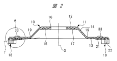
- FIG. 2 is an enlarged cross-sectional view of the rotary tool shown in FIG. 1;
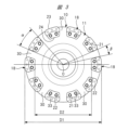
- FIG. It is a front view which shows the grinding surface of a rotary tool.
- It is an enlarged front view showing one grindstone tip attached to a resin substrate.
- 3 is an enlarged cross-sectional view of a portion A in FIG. 2;
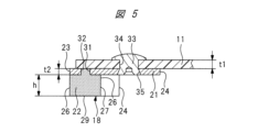
- FIG. FIG. 5 is a cross-sectional view taken along the line BB in FIG. 4;
- FIG. 4 is a cross-sectional view showing a state in which the surface of a member to be ground is ground by a rotary tool attached to a power tool; (A) shows a state in which all abrasive grain layers are pressed against the surface of the member to be ground; B) shows a state in which a part of all the abrasive grain layers is pressed against the surface of the member to be ground.
- FIG. 4 is a cross-sectional view showing a state in which a grindstone chip attached to a flexible resin substrate is grinding following undulations and undulations of a surface to be ground. It is a front view which shows one grindstone tip
- FIG. 10 is an enlarged cross-sectional view taken along line CC in FIG. 9;
- FIG. 4 is a cross-sectional view showing a grindstone tip in a rotary tool of another embodiment;
- FIG. 4 is a cross-sectional view showing a grindstone tip in a rotary tool of another embodiment;
- FIG. 4 is a cross-sectional view showing a grindstone tip in a rotary tool of another embodiment;
- FIG. 1 shows a power tool 1 used for grinding the surface of a member to be ground such as stone or metal.
- This power tool 1 is provided with an output shaft 3 extending in a direction perpendicular to the case body 2 at the tip of a case body 2 in which an electric motor (not shown) is incorporated.
- It is a power tool that A grindstone wheel as a tip tool, that is, a rotary tool 10 is mounted on the output shaft 3 with a mounting bracket 4 on the rear side and a mounting bracket 5 on the front side.
- the mounting bracket 5 is a nut screwed to a male screw (not shown) provided at the tip of the output shaft 3 .
- the rotary tool 10 has a resin substrate 11 made of a resin material and shaped like a disc.
- the resin substrate 11 has a mounting portion 12 mounted on the output shaft 3 by means of mounting brackets 4 and 5, and a mounting portion 13 offset forward of the output shaft 3 with respect to the mounting portion 12.
- An inclined wall portion 14 is provided between the portion 13 and the portion 13 .
- the inclined wall portion 14 has a truncated cone shape as a whole.
- the resin substrate 11 has a central portion formed into a cup shape by the mounting portion 12 and the inclined wall portion 14, and the mounting portion 13, which is the outer peripheral portion, is radially extending. It is a cup type that extends to When the resin substrate 11 is attached to the output shaft 3, the surface facing the member to be ground is the front surface or the front surface, and the opposite surface is the rear surface or back surface.
- fiber reinforced plastic containing fibers and resin
- FRP fiber reinforced plastic
- GFRP epoxy resin
- glass fiber as a reinforcing material
- the base material that is, the matrix
- the base material may be other thermosetting resin such as unsaturated polyester or phenolic resin, or GFRTP using thermoplastic resin such as polyamide resin, polycarbonate resin, polyphenylene sulfide resin, etc.
- CFRP or CFRTP using carbon fiber as the reinforcing material may be used as the resin material.
- the resin substrate 11 made of a resin material such as fiber-reinforced plastic is elastically deformable and flexible compared to a substrate made of metal or hard resin.
- a collar 15 made of a metal material is fixed to the central portion of the mounting portion 12 .
- the collar 15 has a hollow shaft portion 16 through which the output shaft 3 passes and a flat portion 17 arranged on the surface side of the mounting portion 12 . have.
- the resin substrate 11 is attached to the output shaft 3 by abutting the mounting bracket 4 on the rear surface of the mounting portion 12 and tightening the mounting bracket 5 on the surface of the flat portion 17 .
- a plurality of grindstone chips 18 are arranged in the circumferential direction on the surface of the outer peripheral portion of the resin substrate 11, that is, the outer peripheral portion of the mounting portion 13. As shown in FIG. In this rotary tool 10, a total of 10 grindstone chips 18 are arranged on the outer peripheral portion of the resin substrate 11 at regular intervals in the circumferential direction. and integrated with the resin substrate 11 .
- Each grinding wheel tip 18 includes a metal holding plate 21 fixed to the surface of the resin substrate 11 and an abrasive grain layer 22 held by the holding plate 21 .
- the holding plate 21 is attached in a range straddling the radial center portion of the mounting portion 13 that is offset forward of the output shaft 3 with respect to the mounting portion 12 , and the abrasive grain layer 22 is attached to the radially outer peripheral portion of the holding plate 21 .
- attached to the The abrasive grain layer 22 is a hard sintered body formed by heat-treating and sintering a mixed powder of granular synthetic diamond abrasive grains and bond (metal bond) in a heating furnace. It is also called yui chip or simply chip.
- abrasive grains such as CBN (cubic boron nitride) and GC (green silicon carbide) can be used instead of synthetic diamond.
- metal used for the metal bond cobalt, nickel, iron, tungsten-carbite, tungsten, bronze, etc., or a known material in which these are mixed can be used. Any binder such as resinoid or vitrified bond may be used instead of metal bond.
- the abrasive grain layer 22 may be a so-called diamond sintered compact (PCD) having a low binder ratio.
- FIG. 4 is an enlarged front view showing one grindstone tip 18 attached to the resin substrate 11.
- FIG. 5 is an enlarged cross-sectional view of part A in FIG. 2, and
- FIG. 6 is a cross-sectional view taken along the line BB in FIG.
- the holding plate 21 has an arc-shaped outer peripheral surface 23 and an arc-shaped inner peripheral surface 24 extending in the circumferential direction of the resin substrate 11. have the same center of curvature O, and the center of curvature O is the central axis of rotation of the circular resin substrate 11 .
- Both end faces 25 in the circumferential direction of the holding plate 21 are bent surfaces that are convex outward from the end faces 25 .
- Hard resin or the like may be used as the material of the holding plate.
- the distance between the outer peripheral surfaces 23 of the two grindstone tips 18 facing each other through the rotation center axis O that is, the diameter of the rotary tool 10 is D1
- the distance between the two grindstone tips 18 facing each other is D1.
- the diameter D1 is 100 mm
- the diameter D2 is 84 mm.
- the circumferential tip angle ⁇ of each grinding wheel tip 18 is 24 degrees
- the circumferential gap angle ⁇ between two circumferentially adjacent grinding wheel tips 18 is 11 degrees.
- the abrasive grain layer 22 fixed to the holding plate 21 has an outer peripheral surface 26 and an inner peripheral surface 27 .
- the outer peripheral surface 26 is an arcuate surface having a radius of curvature R1 with the center of curvature O, and is coplanar with the outer peripheral surface 23 and is continuous therewith.
- the inner peripheral surface 27 is an arcuate surface with a curvature radius R3 having a center of curvature P at a position radially outwardly displaced from the center of curvature O of the outer peripheral surface 26 .
- the virtual line M is an arc surface with a curvature radius R2 with the curvature center O of the outer peripheral surface 26 as the center of curvature.
- the inner peripheral surface 27 is an arcuate surface indicated by an imaginary line M, and the center of curvature of the outer peripheral surface 26 and the inner peripheral surface 27 is the same point O, the thickness dimension in the radial direction of the abrasive grain layer 22 is along the circumferential direction. almost identical.
- both ends of the abrasive grain layer 22 in the circumferential direction The thickness W2 of the portion is thicker than the thickness W1 of the central portion in the circumferential direction. That is, the abrasive grain layer 22 has a portion where the thickness in the radial direction is larger at the end portions in the circumferential direction than at the center portion in the circumferential direction. As a result, impacts in the rotational direction applied to both ends of the abrasive grain layer 22 during grinding are appropriately dispersed, and damage due to local application of force can be suppressed.
- the thickness W1 is 5 mm, while the thickness W2 is 8 mm.
- the thickness t1 is 1.4 mm and the thickness t2 is 1 mm.
- the thickness t2 is desirably thin and lightweight while ensuring strength for fixing to the resin substrate 11, and is formed to be equal to or thinner than the thickness t1.
- the thickness t2 is in the range of 0.1 to 0.8 times the thickness t1, more preferably in the range of 0.5 to 0.75 times.
- the height of the abrasive grain layer 22, that is, the dimension along the central axis of rotation is h
- the height h is 4 mm.
- the front surface of the abrasive grain layer 22 is a grinding surface 29 that is pressed against the surface of the object to be ground.
- Both circumferential end surfaces of the abrasive grain layer 22 are inclined surfaces 28 that are inclined with respect to the radial direction line.
- the inclined surface 28 has an outward inclined surface 28a radially outside the radial center of the abrasive layer 22 and an inward inclined surface 28b radially inside the central portion.
- the outward inclined surface 28a faces radially outward of the rotary tool 10 about a radial line that contacts the projecting end of the convex curved surface of the inclined surface 28a.
- the inward inclined surface 28b faces the rotary tool 10 radially inward.
- the grindstone tip 18 has a holding plate 21 and an abrasive grain layer 22 bonded thereto, is fixed to the outer peripheral portion of the surface of the resin substrate 11, and the plurality of grindstone tips 18 are separated from each other. Since the abrasive grain layer 22 is bonded to the holding plate 21 made of metal or hard resin, it is neither tilted nor displaced with respect to the holding plate 21 during grinding.
- a region 30 of the resin substrate 11 between the grindstone tips 18 adjacent in the circumferential direction is a flexible material that can be elastically deformed according to the displacement of the grindstone tips 18 during grinding. is the area of As a result, the grindstone tip 18 can be displaced with respect to the resin substrate while maintaining its overall shape without being deformed during grinding.
- a rotary tool 10 with ten abrasive tips 18 has ten flexible regions 30 .
- the holding plate 21 is formed with a bonding hole 31 penetrating through the holding plate 21, and the abrasive grain layer 22 has a convex portion 32 that enters the bonding hole 31.
- the abrasive grain layer 22 is bonded to the surface of the holding plate 21 and the protrusions 32 are bonded to the inner peripheral surface of the bonding hole 31, so that the holding plate 21 and the abrasive grain layer 22 are separated from each other as shown in FIG.
- the holding plate 21 having holes as the bonding holes 31 is placed in a sintering mold, and with the holding plate 21 placed, the abrasive grains and the bond are bonded.
- the mixture is filled into a sintering mold and heat treated.
- the abrasive grain layer 22 to which the holding plate 21 is joined is insert-molded by the sintering mold.
- the holding plate 21 and the abrasive grain layer 22 are joined in a stepped manner, so that the joining strength is enhanced.
- the abrasive grain layer 22 is inserted into the bonding hole 31 formed through the holding plate 21, it is possible to form a groove with a bottom in the holding plate 21 and insert the abrasive grain layer 22 into the groove. Therefore, the holding plate 21 and the abrasive grain layer 22 may be bonded to each other at the stepped bonding surface.
- the holding plate 21 is fixed to the resin substrate 11 by two rivets 33, respectively.
- the resin substrate 11 is formed with mounting holes 34 as grindstone chip fixing portions, and each of the holding plates 21 is formed with two tapered caulking holes 35 .
- the rivet 33 is a projecting portion projecting from the holding plate 21 toward the resin substrate 11 , and the rivet 33 as the projecting portion is inserted into the mounting hole 34 as the grindstone chip fixing portion to fix the holding plate 21 to the resin substrate 11 . do.
- the holding plate 21 and the resin substrate 11 are fixed with the rivets 33, the holding plate 21 can be formed of a metal plate thinner than the resin substrate 11, thereby suppressing imbalance in rotational balance caused by variations in the weight of the grindstone tip 18. be able to.
- the rivets 33 are previously attached to the mounting holes 34 of the resin substrate 11 and the mounting holes 34 of the resin substrate 11 are fixed.
- the crimping hole 35 of the holding plate 21 is inserted into the rivet 33 protruding from the holding plate 21 , and the tip of the rivet 33 is plastically deformed from the side opposite to the insertion side of the crimping hole 35 .
- the rivet 33 as the projecting portion may be fixed to the holding plate 21 by welding, the rivet 33 may be inserted into the mounting hole 34, and the head of the rivet 33 may be plastically deformed.
- each rivet 33 with respect to the holding plate 21 radially overlaps within the groove 36 formed by the inner peripheral surface 27 of the abrasive grain layer 22, as shown in FIG.
- the abrasive grain layer 22 is set to have a smaller thickness at the center in the circumferential direction than at the ends in the circumferential direction, and the rivets 33 are arranged at the center in the circumferential direction and have a greater thickness at both ends in the circumferential direction. Therefore, it is possible to increase the contact area between the grinding surface 29 of the abrasive grain layer 22 and the member to be ground, thereby suppressing an increase in surface pressure.
- FIG. 7 is a cross-sectional view showing a state in which the surface S of the member to be ground V is ground by the rotating tool 10 attached to the power tool.
- FIG. 7(A) shows a state in which the grinding surfaces 29 of all the abrasive grain layers 22 are pressed against the grinding target S of the grinding target member. The state in which the grinding surface 29 of the abrasive grain layer 22 is pressed is maintained.
- FIG. 7B shows a state in which a portion of the grinding surfaces 29 of all the abrasive grain layers 22 is in contact with the grinding surface S of the member V to be ground, and the rotation center axis O is inclined at an angle b.
- the grinding surfaces 29 of some of the abrasive grain layers 22 are pressed against the surface S to be ground, and the other abrasive grain layers 22 are separated from the surface S to be ground.
- the resin substrate 11 When the abrasive grain layer 22 is pressed against the ground surface S of the member V to be ground, the resin substrate 11 is flexible, so that the inclined wall portion 14 is elastically deformed so that the inner diameter on the surface side increases. Grinding is performed with the entire grinding surface 29 of each abrasive grain layer 22 pressed against the surface to be ground. In this state, the edge of the abrasive grain layer 22 is less likely to bite into the surface S to be ground, and the weight of the grindstone tip 18 is suppressed, so that the surface S to be ground S is prevented from being excessively ground. In other words, the amount of grinding can be easily controlled because the pressing force for performing the grinding work appropriately can be given a range. As a result, the surface S to be ground can be ground with high accuracy.
- the vibration applied to the abrasive grain layer 22 is absorbed by the flexible resin substrate 11, the vibration transmitted to the operator is reduced. Since the abrasive grain layer 22 is bonded to the holding plate 21, the abrasive grain layer 22 is not subjected to an external force that deforms it, and the product life of the abrasive grain layer 22 can be suppressed from being shortened.
- the grindstone tip 18 is displaced following the surface of the surface S to be ground, thereby enabling a uniform grinding operation with little unevenness in the amount of grinding.
- excessive grinding caused by the edge of the abrasive grain layer 22 digging into the surface S to be ground is also suppressed in such work.
- the resin substrate 11 does not contain a metal material, even if it is repeatedly elastically deformed due to the displacement of the grindstone tip 18, metal fatigue does not occur, and damage to the resin substrate 11 can be suppressed. It is possible to suppress the deterioration of the product life.
- the end surface of the abrasive grain layer 22 is an inclined surface 28 that is inclined with respect to the radial direction line, even if the projection of the member to be ground hits the end surface, the abrasive grain layer 22 is prevented from being damaged. It is possible to prevent the corners formed by the inclined surfaces 28 from interfering with the deformation of the resin substrate 11 .
- the inclined surface 28 By forming the inclined surface 28 with the outward inclined surface 28a and the inward inclined surface 28b, the inclined surface 28 can be formed on the end surface without increasing the length of the abrasive layer 22 in the circumferential direction.
- the circumferential tip angle ⁇ of the grinding wheel tip 18 is set to 24 degrees, and the gap angle ⁇ is set to 11 degrees.
- the angles at which flexibility can be exhibited are not limited to these angles.
- the tip angle ⁇ should be 10 degrees or more and 30 degrees or less, and the gap angle ⁇ should be 7 degrees or more and 20 degrees or less.
- the thickness t1 of the resin substrate 11, the thickness t2 of the holding plate 21, and the height h of the abrasive grain layer 22 are not limited to the values described above.
- the holding plate 21 is attached in a range straddling the radial center portion of the attachment portion 13 that is offset from the attachment portion 12, the abrasive grain layer 22 is worn as indicated by the virtual line T in FIG. Even so, the connecting portion 19 between the inclined wall portion 14 and the mounting portion 13 can be protected.
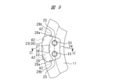
- FIG. 9 is a front view showing one grindstone tip 18 in a rotary tool of another embodiment
- FIG. 10 is an enlarged cross-sectional view taken along line CC in FIG.
- bonding grooves 41 are formed in the outer peripheral surface 23 and the end surface 25 of the holding plate 21 , and the abrasive grain layer 22 is provided with projections 42 that enter the respective bonding grooves 41 .
- the bonding portion between the abrasive grain layer 22 and the holding plate 21 has the bonding groove 41 and the convex portion 42 , and the holding plate 21 and the abrasive grain layer 22 extend in the circumferential direction of the resin substrate 11 . They are joined in a stepped or zigzag shape to increase the joining strength.
- 11 and 12 are cross-sectional views showing a grindstone tip 18 of another embodiment.
- a bonding groove 43 is formed on the back surface of the abrasive grain layer 22, and a convex portion 44 that enters the bonding groove 43 and bonds is provided on the surface of the holding plate 21 so as to protrude forward.
- the joint grooves 43 and the protrusions 44 are provided in plural numbers, for example three each, along the circumferential direction, for example, similarly to the joint holes 31 and the protrusions 32 shown in FIGS. 4 and 5 .
- bonding grooves 45 are formed on the surface of the holding plate 21 , and projections 46 bonded to the bonding grooves 45 are provided on the abrasive grain layer 22 .
- Two bonding grooves 45 and protrusions 46 are provided in pairs in the radial direction, and a plurality of pairs, for example, three pairs, are provided in the circumferential direction.
- the holding plate 21 and the abrasive grain layer 22 are joined in a stepped manner in the circumferential direction, and are also joined in a stepped manner in the radial direction.
- the bonding strength can be increased, and even if vibration is applied to the abrasive grain layer 22 during grinding, Separation or breakage of the abrasive grain layer 22 and the holding plate 21 is prevented, and a reduction in product life is suppressed.
- FIG. 13 is a cross-sectional view showing a grinding wheel tip 18 of another embodiment.
- a holding plate 21 and a rivet 33 are formed with coaxial joint holes 47, and projections 48 are joined to the joint holes 47. is provided on the abrasive grain layer 22 .
- the projections 48 By joining the projections 48 to the holding plate 21 and the rivets 33 in this way, the joining force between the abrasive grain layer 22, the holding plate 21 and the rivets 33 can be increased.
- the holding plate 21 and the rivets 33 are integrally molded.
- the present invention is not limited to the above-described embodiments, and can be modified in various ways without departing from the spirit of the present invention.
- the number of grindstone tips 18 attached to the resin substrate 11 is not limited to ten as in the illustrated embodiment, and various numbers of rotary tools can be used.
- the outer diameter of the rotary tool 10 can also be varied according to the member to be ground.
- the abrasive grain layer is bonded to the holding plate 21 at the time of binding, but after the abrasive grain layer is molded, the abrasive grain layer is fixed to the holding plate by an electrodeposition method using electroplating or a welding method using brazing material.
- the rotary tool of the present invention is applied for grinding a surface to be searched, such as concrete or stone.
Landscapes
- Engineering & Computer Science (AREA)
- Mechanical Engineering (AREA)
- Chemical & Material Sciences (AREA)
- Ceramic Engineering (AREA)
- Inorganic Chemistry (AREA)
- Polishing Bodies And Polishing Tools (AREA)
Priority Applications (2)
| Application Number | Priority Date | Filing Date | Title |
|---|---|---|---|
| CN202280051114.1A CN117677471A (zh) | 2021-07-30 | 2022-07-25 | 旋转工具 |
| JP2023538525A JP7633408B2 (ja) | 2021-07-30 | 2022-07-25 | 回転工具 |
Applications Claiming Priority (2)
| Application Number | Priority Date | Filing Date | Title |
|---|---|---|---|
| JP2021-125427 | 2021-07-30 | ||
| JP2021125427 | 2021-07-30 |
Publications (1)
| Publication Number | Publication Date |
|---|---|
| WO2023008386A1 true WO2023008386A1 (ja) | 2023-02-02 |
Family
ID=85086958
Family Applications (1)
| Application Number | Title | Priority Date | Filing Date |
|---|---|---|---|
| PCT/JP2022/028663 Ceased WO2023008386A1 (ja) | 2021-07-30 | 2022-07-25 | 回転工具 |
Country Status (3)
| Country | Link |
|---|---|
| JP (1) | JP7633408B2 (https=) |
| CN (1) | CN117677471A (https=) |
| WO (1) | WO2023008386A1 (https=) |
Citations (2)
| Publication number | Priority date | Publication date | Assignee | Title |
|---|---|---|---|---|
| JPH11156729A (ja) * | 1997-11-21 | 1999-06-15 | Yano Kazuya | チップ交換可能な砥石車 |
| JP2014042980A (ja) * | 2012-06-11 | 2014-03-13 | Goei Seisakusho:Kk | カップ型回転砥石 |
Family Cites Families (7)
| Publication number | Priority date | Publication date | Assignee | Title |
|---|---|---|---|---|
| JPS5683366U (https=) * | 1979-11-27 | 1981-07-04 | ||
| JP2505097B2 (ja) * | 1993-04-28 | 1996-06-05 | 浩 秋田 | 研磨用砥石およびその製造方法 |
| JP2000094341A (ja) * | 1998-09-22 | 2000-04-04 | Noritake Diamond Ind Co Ltd | ダイヤモンドオフセット研削砥石 |
| JP3762754B2 (ja) * | 2003-03-18 | 2006-04-05 | 株式会社呉英製作所 | ディスク状砥石 |
| JP2010069604A (ja) | 2008-09-22 | 2010-04-02 | Asahi Diamond Industrial Co Ltd | 回転工具 |
| JP2015223691A (ja) * | 2014-05-30 | 2015-12-14 | 天龍製鋸株式会社 | カップホイール |
| CN204868582U (zh) * | 2015-09-02 | 2015-12-16 | 郑州华菱超硬材料有限公司 | 既能打磨又能切割的超硬角磨片 |
-
2022
- 2022-07-25 CN CN202280051114.1A patent/CN117677471A/zh active Pending
- 2022-07-25 JP JP2023538525A patent/JP7633408B2/ja active Active
- 2022-07-25 WO PCT/JP2022/028663 patent/WO2023008386A1/ja not_active Ceased
Patent Citations (2)
| Publication number | Priority date | Publication date | Assignee | Title |
|---|---|---|---|---|
| JPH11156729A (ja) * | 1997-11-21 | 1999-06-15 | Yano Kazuya | チップ交換可能な砥石車 |
| JP2014042980A (ja) * | 2012-06-11 | 2014-03-13 | Goei Seisakusho:Kk | カップ型回転砥石 |
Also Published As
| Publication number | Publication date |
|---|---|
| JPWO2023008386A1 (https=) | 2023-02-02 |
| CN117677471A (zh) | 2024-03-08 |
| JP7633408B2 (ja) | 2025-02-19 |
Similar Documents
| Publication | Publication Date | Title |
|---|---|---|
| EP2361725B1 (en) | Grinding wheel | |
| US7744447B2 (en) | Abrasive disc | |
| US8585470B2 (en) | Wearable backing for an abrasive flap disk | |
| US6428406B1 (en) | Soft polishing disc with holes and method of manufacturing the same | |
| US20130331016A1 (en) | Cup type grinding wheel | |
| JP2004276197A (ja) | ディスク状砥石 | |
| US20130331015A1 (en) | Cup type grinding wheel | |
| CN102026777A (zh) | 粗磨磨削盘 | |
| JP7633408B2 (ja) | 回転工具 | |
| JPH11239979A (ja) | 研磨用回転砥石 | |
| JP3811463B2 (ja) | 研磨工具 | |
| JPH11156729A (ja) | チップ交換可能な砥石車 | |
| US12564917B2 (en) | Buffing pad | |
| EP4635663A1 (en) | Tool insert for cutting or grinding applications | |
| JP3111041U (ja) | 平形カップブラシ | |
| CN214869717U (zh) | 一种超精密研磨金刚石砂轮 | |
| JP7560895B2 (ja) | 加工用砥石及びコアドリル | |
| JPH11188637A (ja) | 研削ホイール及びその製造方法 | |
| CN216299022U (zh) | 一种超宽组合倒角砂轮 | |
| JP7233132B2 (ja) | 回転刃具 | |
| CN216098421U (zh) | 一种重负荷砂轮 | |
| JP2004338022A (ja) | ディスク砥石およびその製造方法 | |
| JP7020717B1 (ja) | 回転刃具 | |
| JP5307686B2 (ja) | 回転砥石 | |
| JPH08132348A (ja) | 曲面加工用研摩工具 |
Legal Events
| Date | Code | Title | Description |
|---|---|---|---|
| 121 | Ep: the epo has been informed by wipo that ep was designated in this application |
Ref document number: 22849447 Country of ref document: EP Kind code of ref document: A1 |
|
| WWE | Wipo information: entry into national phase |
Ref document number: 202280051114.1 Country of ref document: CN Ref document number: 2023538525 Country of ref document: JP |
|
| NENP | Non-entry into the national phase |
Ref country code: DE |
|
| 122 | Ep: pct application non-entry in european phase |
Ref document number: 22849447 Country of ref document: EP Kind code of ref document: A1 |