WO2023007603A1 - 室外機、および冷凍サイクル装置 - Google Patents
室外機、および冷凍サイクル装置 Download PDFInfo
- Publication number
- WO2023007603A1 WO2023007603A1 PCT/JP2021/027848 JP2021027848W WO2023007603A1 WO 2023007603 A1 WO2023007603 A1 WO 2023007603A1 JP 2021027848 W JP2021027848 W JP 2021027848W WO 2023007603 A1 WO2023007603 A1 WO 2023007603A1
- Authority
- WO
- WIPO (PCT)
- Prior art keywords
- fan
- outdoor unit
- rotation axis
- bell mouth
- housing
- Prior art date
- Legal status (The legal status is an assumption and is not a legal conclusion. Google has not performed a legal analysis and makes no representation as to the accuracy of the status listed.)
- Ceased
Links
Images


Classifications
-
- F—MECHANICAL ENGINEERING; LIGHTING; HEATING; WEAPONS; BLASTING
- F24—HEATING; RANGES; VENTILATING
- F24F—AIR-CONDITIONING; AIR-HUMIDIFICATION; VENTILATION; USE OF AIR CURRENTS FOR SCREENING
- F24F1/00—Room units for air-conditioning, e.g. separate or self-contained units or units receiving primary air from a central station
- F24F1/06—Separate outdoor units, e.g. outdoor unit to be linked to a separate room comprising a compressor and a heat exchanger
- F24F1/38—Fan details of outdoor units, e.g. bell-mouth shaped inlets or fan mountings
Definitions
- the present disclosure relates to outdoor units and refrigeration cycle devices.
- Patent Document 1 describes an outdoor unit of an air conditioner that includes a propeller fan and a bell mouth that surrounds the propeller fan.
- the gap between the propeller fan and the bell mouth is made small, and air is blown in the axial direction from the gap between the propeller fan and the bell mouth.
- Methods are known to reduce escaping airflow.
- the smaller the gap between the propeller fan and the bell mouth the greater the effect of the friction that the propeller fan receives from the stationary air in the vicinity of the bell mouth, and the greater the braking force generated in the propeller fan. Therefore, there is a problem that simply reducing the gap between the propeller fan and the bellmouth cannot sufficiently improve the air blowing efficiency.
- an object of the present disclosure is to provide an outdoor unit having a structure capable of improving the blowing efficiency of a blower fan, and a refrigeration cycle apparatus including such an outdoor unit.
- One aspect of the outdoor unit according to the present disclosure is an outdoor unit of a refrigeration cycle apparatus, which includes a housing having an opening, and a rotor disposed inside the housing so as to face the opening. a blower fan; and an annular bell mouth that surrounds at least a portion of the rotor blades around the rotation axis of the rotor blades, wherein the bell mouth is arranged around the rotation axis with respect to the housing and the rotor blades. Relative rotation is possible.
- One aspect of the refrigeration cycle apparatus according to the present disclosure includes the outdoor unit described above.
- the blowing efficiency of the blower fan can be improved.
- FIG. 1 is a schematic diagram showing a schematic configuration of a refrigeration cycle apparatus according to Embodiment 1.
- FIG. 1 is a perspective view showing an outdoor unit according to Embodiment 1.
- FIG. Fig. 2 is a front view of the outdoor unit with the fan grille removed according to the first embodiment;
- FIG. 2 is a partial cross-sectional view of part of the outdoor unit according to Embodiment 1 as seen from above.
- Fig. 2 is a perspective view showing part of the outdoor unit according to Embodiment 1;
- 1 is a perspective view showing a bell mouth according to Embodiment 1.
- FIG. 4 is a perspective view showing a portion of the bell mouth and a fixing member according to Embodiment 1.
- FIG. 1 is a schematic diagram showing a schematic configuration of a refrigeration cycle apparatus according to Embodiment 1.
- FIG. 1 is a perspective view showing an outdoor unit according to Embodiment 1.
- FIG. Fig. 2 is a front view of the outdoor unit with the fan grille
- FIG. 4 is a diagram for explaining the flow of air blown out from the outdoor unit in Embodiment 1.
- FIG. FIG. 4 is a diagram for explaining velocity distribution of air intervening in a fan gap;
- Fig. 10 is a front view of the outdoor unit according to Embodiment 2;
- FIG. 11 is a partial cross-sectional view of a part of the outdoor unit according to Embodiment 2 as viewed from above;
- FIG. 11 is a partial cross-sectional view of a part of the outdoor unit according to Embodiment 3 as viewed from above;
- the drawings show the X-axis, Y-axis, and Z-axis as appropriate.
- the X-axis indicates the front-rear direction of the outdoor units of the following embodiments.
- the Y-axis indicates the width direction of the outdoor unit orthogonal to the front-rear direction.
- the Z-axis indicates the vertical direction.
- the front-rear direction, width direction, and vertical direction are directions orthogonal to each other.
- the width direction is the lateral direction of the outdoor unit.
- the side in the width direction to which the Y-axis arrow points (+Y side) is the left side of the outdoor unit, and the side opposite to the side in the width direction to which the Y-axis arrow points (-Y side) is the right side of the outdoor unit.
- the side of the width direction where the arrow of the Y axis points (+Y side) that is, the left side is called “one side in the width direction”
- the side opposite to the side of the width direction where the arrow of the Y axis points (- Y side) is called "the other side in the width direction”.
- FIG. 1 is a schematic diagram showing a schematic configuration of a refrigeration cycle apparatus 100 according to Embodiment 1.
- FIG. Refrigeration cycle device 100 in Embodiment 1 is an air conditioner. As shown in FIG. 1 , the refrigeration cycle device 100 includes an outdoor unit 10, an indoor unit 20, and a circulation path section 18. The outdoor unit 10 is arranged outdoors. The indoor unit 20 is arranged indoors. The outdoor unit 10 and the indoor unit 20 are connected to each other by a circulation path portion 18 through which the refrigerant 19 circulates.
- the refrigeration cycle device 100 can adjust the temperature of the indoor air by exchanging heat between the refrigerant 19 flowing through the circulation path portion 18 and the indoor air in which the indoor unit 20 is arranged.
- the refrigerant 19 for example, a fluorine-based refrigerant having a low global warming potential (GWP), a hydrocarbon-based refrigerant, or the like can be used.
- GWP global warming potential
- hydrocarbon-based refrigerant or the like
- the outdoor unit 10 has a housing 11, a compressor 12, a heat exchanger 13, a flow control valve 14, a blower fan 15, a four-way valve 16, and a controller 17.
- a compressor 12 , a heat exchanger 13 , a flow control valve 14 , a blower fan 15 , a four-way valve 16 , and a controller 17 are housed inside the housing 11 .
- the compressor 12 , the heat exchanger 13 , the flow control valve 14 and the four-way valve 16 are provided in a portion of the circulation path section 18 located inside the housing 11 .
- Compressor 12 , heat exchanger 13 , flow control valve 14 , and four-way valve 16 are connected by a portion of circulation path portion 18 located inside housing 11 .
- the four-way valve 16 is provided in a portion of the circulation path portion 18 that is connected to the discharge side of the compressor 12 .
- the four-way valve 16 can reverse the direction of the refrigerant 19 flowing through the circulation path portion 18 by switching a part of the circulation path portion 18 .
- the path connected by the four-way valve 16 is the path indicated by the solid line in the four-way valve 16 in FIG. 1
- the refrigerant 19 flows through the circulation path portion 18 in the direction indicated by the solid arrow in FIG.
- the path connected by the four-way valve 16 is the path indicated by the dashed line in the four-way valve 16 in FIG. 1
- the refrigerant 19 flows in the circulation path section 18 in the direction indicated by the dashed arrow in FIG.
- the indoor unit 20 has a housing 21, a heat exchanger 22, and a blower fan 23.
- a heat exchanger 22 and a blower fan 23 are housed inside the housing 21 .
- the indoor unit 20 is capable of a cooling operation for cooling the air in the room in which the indoor unit 20 is arranged and a heating operation for warming the air in the room in which the indoor unit 20 is arranged.
- the refrigerant 19 flowing through the circulation path portion 18 flows in the direction indicated by the solid arrow in FIG. That is, when the indoor unit 20 is in a cooling operation, the refrigerant 19 flowing through the circulation path portion 18 flows through the compressor 12, the heat exchanger 13 of the outdoor unit 10, the flow control valve 14, and the heat exchanger 22 of the indoor unit 20. in that order back to the compressor 12 .
- the heat exchanger 13 inside the outdoor unit 10 functions as a condenser
- the heat exchanger 22 inside the indoor unit 20 functions as an evaporator.
- the refrigerant 19 flowing through the circulation path portion 18 flows in the direction indicated by the dashed line in FIG.
- the refrigerant 19 flowing through the circulation path portion 18 flows through the compressor 12, the heat exchanger 22 of the indoor unit 20, the flow control valve 14, and the heat exchanger 13 of the outdoor unit 10. in that order back to the compressor 12 .
- the heat exchanger 13 inside the outdoor unit 10 functions as an evaporator
- the heat exchanger 22 inside the indoor unit 20 functions as a condenser.
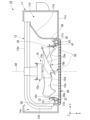
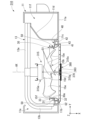
- FIG. 2 is a perspective view showing the outdoor unit 10.
- FIG. 3 is a front view (+X direction) of the outdoor unit 10 with the fan grill 60 removed.
- FIG. 4 is a partial cross-sectional view of part of the outdoor unit 10 as seen from above.
- FIG. 5 is a perspective view showing part of the outdoor unit 10. FIG. In FIG. 4, illustration of the rear panel of the housing 11 is omitted. In FIG. 5, illustration of part of the housing 11 is omitted.
- the housing 11 of the outdoor unit 10 has a substantially rectangular parallelepiped box shape.
- the housing 11 has an opening 11b.
- the opening 11b is provided in the front panel 11a located on the front side (+X side) of the housing 11 .
- the opening 11b passes through the front panel 11a in the front-rear direction (X-axis direction) and opens forward.
- the opening 11b is a circular hole centered on a rotation axis AX, which will be described later.
- the inner edge of the opening 11b is provided with a bearing holding portion 11c protruding rearward (-X direction).
- the bearing holding portion 11c has a cylindrical shape centered on the rotation axis AX and opening on both sides in the front-rear direction.
- the inner peripheral surface of the bearing holding portion 11c constitutes the inner peripheral surface of the opening portion 11b.
- the bearing holding portion 11c holds therein a bearing 40, which will be described later.
- a partition member 11d that divides the inside of the housing 11 into a fan room 11e and a machine room 11f in the width direction (Y-axis direction).
- a heat exchanger 13 and a blower fan 15 are accommodated in the fan chamber 11e.
- the heat exchanger 13 in the first embodiment has a substantially L shape when viewed in the vertical direction.
- the heat exchanger 13 has a first portion 13a extending in the width direction and a second portion 13b extending forward (+X direction) from the end of the first portion 13a on the other width direction side ( ⁇ Y side).
- the machine room 11f is positioned on one widthwise side (+Y side) of the fan room 11e.
- the compressor 12 and the controller 17 are housed in the machine room 11f.
- the blower fan 15 in Embodiment 1 is a propeller fan. As shown in FIGS. 4 and 5 , the blower fan 15 is positioned in front of the heat exchanger 13 (+X direction). More specifically, the blower fan 15 is located in front of the first portion 13a of the heat exchanger 13 and located on one widthwise side (+Y side) of the second portion 13b. As shown in FIG. 4, the blower fan 15 has a motor 15a and rotary blades 15b. The motor 15a has a forwardly projecting shaft 15c. A rotor blade 15b is fixed to the front end of the shaft 15c.
- the rotor 15b is rotated around the rotation axis AX by the motor 15a.
- the rotation axis AX is a virtual axis extending in the front-rear direction (X-axis direction). That is, in Embodiment 1, the axial direction of the rotation axis AX is the front-rear direction.
- the radial direction around the rotation axis AX is simply called “radial direction”
- the circumferential direction around the rotation axis AX is simply called "circumferential direction”.
- the rotor 15b is arranged inside the housing 11 so as to face the opening 11b. As shown in FIG. 3, the entire rotor blade 15b is located inside the inner edge of the opening 11b when viewed from the front (+X direction). As shown in FIG. 4, the rotor 15b is located behind the opening 11b (-X direction).
- the rotor blade 15b has a base portion 15d fixed to the shaft 15c of the motor 15a, and a plurality of blade portions 15e protruding radially outward from the base portion 15d. A plurality of blade portions 15e are arranged along the circumferential direction. In Embodiment 1, three blade portions 15e are provided.
- the outdoor unit 10 further has a bellmouth 30, a bearing 40, and a fixing member 50.
- the bellmouth 30 is a member that guides air blown forward (+X direction) from the blower fan 15 .
- the bell mouth 30 is also called a shroud.
- Bell mouth 30 is fixed to bearing 40 by fixing member 50 and attached to housing 11 via bearing 40 .
- the bellmouth 30 has an annular shape surrounding at least a portion of the rotor blade 15b around the rotation axis AX of the rotor blade 15b.
- the bellmouth 30 surrounds the front portion of the rotor blade 15b around the rotation axis AX.
- a rear portion of the rotor blade 15b protrudes rearward (-X direction) from the bell mouth 30.
- a gap is provided between the bellmouth 30 and the rotor 15b in the radial direction. This gap is called a fan gap G1.
- the fan gap G1 is a radial gap between the inner peripheral surface 30a of the bellmouth 30 and the radial outer edge portion 15f of the blade portion 15e.
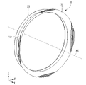
- FIG. 6 is a perspective view showing the bell mouth 30.
- the bell mouth 30 has a trumpet shape opening forward (+X direction).
- the bellmouth 30 is cylindrical with openings on both sides in the front-rear direction (X-axis direction) centering on the rotation axis AX.
- the bellmouth 30 has a base portion 31 , a front enlarged diameter portion 32 and a rear enlarged diameter portion 33 .
- the inner diameter of the base 31 and the outer diameter of the base 31 are constant.
- the front enlarged diameter portion 32 is connected to the front end portion of the base portion 31 .
- the inner diameter of the front enlarged diameter portion 32 and the outer diameter of the front enlarged diameter portion 32 increase toward the front.
- the rear enlarged diameter portion 33 is connected to the rear end portion of the base portion 31 .
- the inner diameter of the rear enlarged diameter portion 33 and the outer diameter of the rear enlarged diameter portion 33 increase toward the rear (-X direction).
- the dimension of the front enlarged diameter portion 32 in the front-rear direction (X-axis direction) is larger than the dimension of the rear enlarged diameter portion 33 in the front-rear direction.
- a front portion of the rotor blade 15 b is arranged radially inward of the base portion 31 and radially inward of the rear enlarged diameter portion 33 .
- the front enlarged diameter portion 32 of the bell mouth 30 has a shape in which four portions along the circumferential direction are notched.
- the bearing 40 is arranged inside the opening 11b.
- the bearing 40 in Embodiment 1 is a ball bearing.
- the bearing 40 has an inner ring 41 , an outer ring 42 and a plurality of balls 43 .
- the inner ring 41 and the outer ring 42 are annular with the rotation axis AX as the center.
- the outer ring 42 is positioned radially outward of the inner ring 41 .
- the plurality of balls 43 are positioned radially between the inner ring 41 and the outer ring 42 .
- the plurality of balls 43 are arranged along the circumferential direction between the inner ring 41 and the outer ring 42 in the radial direction.
- the inner ring 41 and the outer ring 42 are connected via a plurality of balls 43 so as to be relatively rotatable about the rotation axis AX.
- the outer ring 42 is fixed to the inner peripheral surface of the bearing holding portion 11c, that is, the inner peripheral surface of the opening 11b. Thereby, the bearing 40 is attached to the housing 11 .
- the inner ring 41 is fixed to the outer peripheral surface of the bellmouth 30 via a fixing member 50 .
- the bell mouth 30 fixed to the inner ring 41 is rotatable relative to the outer ring 42 fixed to the housing 11 around the rotation axis AX. That is, the bell mouth 30 can rotate relative to the housing 11 around the rotation axis AX.
- the bell mouth 30 is attached to the housing 11 via the bearing 40 so as to be rotatable around the rotation axis AX.
- the bellmouth 30 since the bellmouth 30 is not fixed to the rotary blade 15b, it can also rotate relative to the rotary blade 15b around the rotation axis AX.
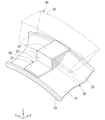
- FIG. 7 is a perspective view showing part of the bell mouth 30 and the fixing member 50.
- the fixing member 50 is a metal fitting that fixes the bellmouth 30 and the inner ring 41 of the bearing 40 .
- the fixing member 50 has a first fixing portion 51 , a second fixing portion 52 and a connecting portion 53 .
- the first fixing part 51 and the second fixing part 52 have a substantially rectangular plate shape whose plate surface faces the radial direction.
- the first fixing portion 51 and the second fixing portion 52 are curved along the circumferential direction.
- the first fixing portion 51 is fixed to the outer peripheral surface of the base portion 31 of the bell mouth 30 .
- the second fixing portion 52 is fixed to the inner peripheral surface of the inner ring 41 .
- the second fixing portion 52 is located radially outside and forward (+X direction) of the first fixing portion 51 .
- the second fixing portion 52 is positioned radially outward of the front enlarged diameter portion 32 .
- the connecting portion 53 has a substantially rectangular plate shape with a plate surface facing in the front-rear direction (X-axis direction).
- the connecting portion 53 connects the front end of the first fixing portion 51 and the rear ( ⁇ X side) end of the second fixing portion 52 .
- a plurality of fixing members 50 are provided at intervals in the circumferential direction.
- four fixing members 50 are provided at regular intervals along the circumference.
- the outdoor unit 10 further has a fan grill 60 arranged to face the rotor blades 15b.
- the fan grill 60 is positioned in front of the rotor blade 15b.
- the fan grill 60 is positioned outside the housing 11 .
- the fan grille 60 covers the opening 11b and the rotor blades 15b from the front.
- the outer peripheral edge of the fan grill 60 is fixed to the front surface of the front panel 11 a of the housing 11 .
- the fan grille 60 can prevent a user or the like from accidentally touching the rotating blades 15b.
- the fan grille 60 has a substantially rectangular shape when viewed from the front (+X direction).
- the fan grill 60 has a plurality of first grill portions 61 and a plurality of second grill portions 62 .
- the plurality of first grill portions 61 are bar-shaped and extend in the vertical direction.
- the plurality of first grill portions 61 are arranged at intervals in the width direction (Y-axis direction).
- the plurality of second grill portions 62 are bar-shaped and extend in the width direction.
- the plurality of second grill portions 62 are arranged at intervals in the vertical direction.
- the plurality of first grill portions 61 and the plurality of second grill portions 62 form the fan grill 60 in a grid pattern.
- FIG. 8 is a diagram for explaining the flow of air blown out from the outdoor unit 10.
- FIG. FIG. 8 shows the outdoor unit 10 with the fan grill 60 removed.
- air is blown forward (+X direction) of the outdoor unit 10 from the opening 11b.
- the air blown forward of the outdoor unit 10 by the blower fan 15 becomes a spiral swirling flow AF that travels forward and spreads radially outward around the rotation axis AX.
- the velocity V of the air in the swirling flow AF includes an axial component Vx along the axial direction of the rotation axis AX, that is, the front-rear direction (X-axis direction), a radial component Vr along the radial direction of the rotation axis AX, and a rotational component Vr. and a circumferential component V ⁇ along the circumferential direction about the axis AX.
- the axial component Vx corresponding to the air volume is greater than the radial component Vr and the circumferential component V ⁇
- the circumferential component V ⁇ caused by the rotation of the rotor blades 15b is greater than the radial component Vr.
- the pressure on the downstream side, that is, the front side (+X side) of the rotor blade 15b that sends air is higher than the pressure on the upstream side, that is, the rear side (-X side) of the rotor blade 15b. Therefore, part of the air that has passed through the rotor blade 15b from the rear side to the front side flows from the front side where the pressure is high to the rear side where the pressure is low through the gap between the bellmouth 30 and the rotor blade 15b, that is, the fan gap G1. flow. Therefore, the air sent by the blower fan 15 may leak rearward through the fan gap G1, and the blowing amount of the blower fan 15 may decrease. Therefore, it is generally considered that the blowing efficiency of the blower fan 15 can be improved by making the fan gap G1 smaller.
- the fan gap G1 is made too small, there is a possibility that the vanes 15e will extend due to centrifugal force and collide with the bellmouth 30 when the rotor blades 15b rotate. Moreover, there is a possibility that the blade portion 15e may come into contact with the bellmouth 30 due to vibration of at least one of the housing 11 and the rotor blade 15b.
- the size of the fan gap G1 also varies. Considering these factors, the fan gap G1 must be designed to be large with a certain amount of margin so that the rotor blades 15b do not contact the bell mouth 30. As shown in FIG. Therefore, there is a limit to reducing the fan gap G1, and there is also a limit to improving the blowing efficiency of the blower fan 15 by reducing the fan gap G1.
- Air also intervenes in the fan gap G1. Therefore, when the rotor blade 15b rotates, friction between the rotor blade 15b and the air causes a braking force to stop the rotation of the rotor blade 15b.
- the method of improving the blowing efficiency of the blower fan 15 by reducing the fan gap G1 is not only limited by the dimensional restrictions of each part, There is also a possibility that the friction may rather reduce the air blowing efficiency. Therefore, there is a problem that the blowing efficiency of the blower fan 15 cannot be sufficiently improved by simply reducing the fan gap G1.
- the bellmouth 30 is rotatable about the rotation axis AX relative to the housing 11 and the rotor blades 15b. That is, the bellmouth 30 is in a state of being freely rotatable with respect to the housing 11 and the rotor blades 15b. Therefore, when the air present in the fan gap G1 is dragged by the rotor blades 15b and tries to move in the direction in which the rotor blades 15b rotate, the bell mouth 30 receives a frictional force from the air contacting the inner peripheral surface 30a of the bell mouth 30. As a result, the rotary blade 15b starts to rotate around the rotation axis AX in the same direction as the rotary blade 15b.
- the air intervening in the fan gap G1 will be becomes easier to flow in the direction of rotation. Therefore, the air intervening in the fan gap G1 is less likely to hinder the rotation of the rotor blades 15b, and the braking force that the rotor blades 15b receive from the air intervening in the fan gap G1 can be reduced. Therefore, the blowing efficiency of the blower fan 15 can be improved.
- FIG. 9 is a diagram for explaining the velocity distribution of air intervening in the fan gap G1.
- a velocity distribution VD1 indicated by a solid line in FIG. 9 is the velocity distribution of air intervening in the fan gap G1 in the first embodiment.
- a velocity distribution VD2 indicated by a two-dot chain line in FIG. 9 is the velocity distribution of air intervening in the fan gap G1 when the bell mouth 30 is fixed to the housing 11 so as not to rotate.
- the frictional force (shear stress) generated on the surface of the object that the fluid contacts is proportional to the velocity gradient of the fluid on the surface of the object.
- ⁇ the frictional force (shear stress)
- dv/dr the velocity gradient.
- ⁇ the viscosity coefficient of air. Therefore, when the bell mouth 30 is fixed to the housing 11 and the air velocity distribution becomes the velocity distribution VD2, the frictional force generated on the inner peripheral surface 30a of the bell mouth 30 also acts on the radial outer edge 15f of the blade 15e. The resulting frictional force is also relatively large. Therefore, the braking force generated in the rotor blades 15b due to friction with air is relatively large.
- the rotation of the bellmouth 30 causes the air contacting the inner peripheral surface 30a to move in the same direction as the rotor 15b. and the air velocity at the radial outer edge portion 15f of the blade portion 15e becomes smaller than the velocity distribution VD2.
- the air velocity gradient VRb1 on the inner peripheral surface 30a of the bell mouth 30 and the velocity gradient VRf1 on the radial outer edge 15f of the vane part 15e are higher than the velocity gradients VRb2 and VRf2 in the velocity distribution VD2. become smaller.
- both the frictional force generated on the inner peripheral surface 30a of the bell mouth 30 and the frictional force generated on the radial outer edge 15f of the blade portion 15e are reduced compared to the case where the bellmouth 30 is fixed to the housing 11. becomes smaller. Therefore, the braking force generated in the rotor blade 15b due to friction with air can be reduced. Therefore, the blowing efficiency of the blower fan 15 can be improved.
- the rotational speed Vb of the bell mouth 30 is, for example, smaller than the rotational speed Vf of the rotor 15b.
- FIG. 9 shows an example in which the rotational speed Vb of the bellmouth 30 is half or less than the rotational speed Vf of the rotor blade 15b.
- the rotational speed Vb of the bellmouth 30 is the frictional force generated in the bellmouth 30 by the air in the fan gap G1, that is, the force to rotate the bellmouth 30 and the frictional force the inner ring 41 of the bearing 40 receives from the balls 43. The speed is balanced with the rotational resistance that the bell mouth 30 receives.
- the rotational speed Vb of the bell mouth 30 does not increase to the extent that the frictional force between the inner ring 41 and the balls 43 increases.
- the rotational speed at which the load is minimized is reached. Therefore, an excessive load is not applied to the blower fan 15 for rotating the bellmouth 30 through the air, and the rotation speed Vb of the bellmouth 30 is adjusted according to the rotation speed Vf of the rotor blade 15b. automatically adjusted to minimize the load on As a result, even if the rotation speed Vf of the rotor blade 15b changes, the load applied to the blower fan 15 can be minimized according to the rotation speed Vf. Therefore, power consumption of the blower fan 15 can be reduced. Such an effect is more useful when applied to an inverter-type air conditioner in which the rotation speed of the blower fan 15 changes steplessly.
- the bell mouth 30 is attached to the housing 11 via the bearing 40 so as to be rotatable around the rotation axis AX. Therefore, the bellmouth 30 can be easily made relatively rotatable about the rotation axis AX with respect to the housing 11 and the rotor blades 15b. Moreover, by using the bearing 40, the rotational resistance generated in the bell mouth 30 when the bell mouth 30 rotates can be reduced.
- FIG. 10 is a diagram of the outdoor unit 210 of Embodiment 2 as seen from the front (+X direction).
- FIG. 11 is a partial cross-sectional view of part of the outdoor unit 210 viewed from above.
- the description may be omitted by appropriately assigning the same reference numerals to the same configurations as those of the above-described embodiment.
- the fan grille 260 in the second embodiment has a circular shape centered on the rotation axis AX.
- the fan grill 260 has a plurality of first grill portions 261 and a plurality of second grill portions 262 .
- the plurality of first grill portions 261 have an annular shape centered on the rotation axis AX.
- the plurality of first grill portions 261 are arranged side by side at intervals in the radial direction.
- the radially inner first grill portion 261 has a smaller inner diameter
- the radial outer first grill portion 261 has a larger inner diameter.
- the plurality of second grill portions 262 linearly extend in the radial direction from the radially innermost first grill portion 261 to the radially outermost first grill portion 261 .
- the plurality of second grill portions 262 are arranged side by side at intervals in the circumferential direction. Each of the plurality of second grill portions 262 is connected to the plurality of first grill portions 261 .
- the proportion of fan grill 260 occupied by first grill portion 261 is greater than the proportion of fan grill 260 occupied by second grill portion 262 .
- the fan grille 260 has a plurality of through holes 263 that penetrate the fan grille 260 in the axial direction of the rotation axis AX, that is, in the front-rear direction (X-axis direction).
- the plurality of through-holes 263 are formed inside surrounded by a pair of radially adjacent first grill portions 261 and a pair of circumferentially adjacent second grill portions 262 .
- the through hole 263 has an arcuate shape extending in the circumferential direction around the rotation axis AX.
- the radial outer edge of the fan grille 260 is fixed to the front (+X side) surface of the inner ring 41 of the bearing 40 .
- fan grille 260 is fixed to bell mouth 30 via bearing 40 in the second embodiment.
- the fan grille 260 is rotatable around the rotation axis AX together with the bell mouth 30 . That is, in the second embodiment, the fan grille 260 is rotatable about the rotation axis AX relative to the housing 11 and the rotor blades 15b.
- Other configurations of the outdoor unit 210 are the same as the other configurations of the outdoor unit 10 of the first embodiment.
- the air blown out from the blower fan 15 forms a swirling flow AF swirling around the rotation axis AX.
- Part of the air blown out as swirling flow AF collides with the first grill portion 261 or the second grill portion 262 of the fan grill 260 when passing through the fan grill 260 .
- pressure loss occurs in the air blown out by the blower fan 15 . Therefore, the blowing efficiency of the blower fan 15 may decrease.
- the fan grill 260 is rotatable about the rotation axis AX relative to the housing 11 and the rotor blades 15b. That is, the fan grille 260 is in a state of being freely rotatable with respect to the housing 11 and the rotor blades 15b. Therefore, when the air blown out as the swirling flow AF is about to pass through the fan grille 260, if a fluid force around the rotation axis AX is applied to the fan grille 260, the fan grille 260 is moved by the fluid force to move the rotor blades. 15b begins to rotate around the rotation axis AX in the same direction as the direction in which 15b rotates.
- the resistance that the air receives from the fan grille 260 can be reduced compared to the case where the fan grille 260 is fixed to the housing 11 and is stationary. Therefore, the pressure loss that occurs when the air blown by the blower fan 15 passes through the fan grill 260 can be reduced. Therefore, the blowing efficiency of the blower fan 15 can be further improved.
- the fan grille 260 is fixed to the bellmouth 30 . Therefore, both the bell mouth 30 and the fan grill 260 rotate around the rotation axis AX.
- the force about the rotation axis AX received by the fan grille 260 from the air blown out as the swirling flow AF can be used as a force for rotating the bell mouth 30 about the rotation axis AX.
- the force about the rotation axis AX received by the bell mouth 30 from the air intervening in the fan gap G1 can be used as a force for rotating the fan grille 260 about the rotation axis AX. Therefore, both the bell mouth 30 and the fan grill 260 can be easily rotated around the rotation axis AX. Therefore, the braking force generated in the rotor blades 15b and the pressure loss generated when the air blown by the blower fan 15 passes through the fan grill 260 can be further reduced. Thereby, the ventilation efficiency of the ventilation fan 15 can be improved more.
- the pressure loss that the air passing through the fan grill 260 receives The pressure loss of the air increases when the air collides perpendicularly with the first grill portion 261 and the second grill portion 262 that constitute the fan grill 260, and the air travels along the first grill portion 261 and the second grill portion 262. It becomes smaller when flowing.
- the velocity V of the air blown out of the outdoor unit 10 as the swirling flow AF by the blower fan 15 includes the axial component Vx, the circumferential component V ⁇ , and the radial component Vr.
- the axial component Vx since it is a velocity component in the direction of perpendicularly colliding with the fan grill 260, it is difficult to reduce the pressure loss.
- the pressure loss of the circumferential component V ⁇ and the radial component Vr varies depending on the shape of the fan grille 260 .
- the pressure loss received by the radial component Vr perpendicularly colliding with the portions increases.
- the pressure loss received by the circumferential direction component V ⁇ perpendicularly colliding with such portions increases.
- the circumferential component V ⁇ tends to be greater than the radial component Vr.
- the fan grille 260 is shaped so that the portion extending in the radial direction is small, so that the pressure loss generated in the air passing through the fan grille 260 can be preferably reduced.
- the fan grille 260 has a plurality of through holes 263 extending in the circumferential direction around the rotation axis AX. Therefore, the shape of the fan grille 260 can be easily made to have a large portion extending in the circumferential direction and a small portion extending in the radial direction. As a result, the pressure loss received by the circumferential component V ⁇ can be suitably reduced, and the pressure loss occurring in the air passing through the fan grill 260 can be suitably reduced. Therefore, the blowing efficiency of the blower fan 15 can be further improved.
- the fan grille 260 also rotates in the direction in which the rotor blades 15b rotate. move in the circumferential direction. That is, by rotating the fan grill 260, the portion that tends to cause pressure loss in the circumferential direction component V ⁇ moves in the same direction as the direction of the circumferential direction component V ⁇ . As a result, the circumferential component V ⁇ is less likely to collide with the portion of the fan grill 260 extending in the radial direction, and the pressure loss caused by the circumferential component V ⁇ can be further reduced. Therefore, the blowing efficiency of the blower fan 15 can be further improved.
- the plurality of first grill portions 261 are arranged concentrically around the rotation axis AX. Therefore, even if the fan grille 260 rotates around the rotation axis AX, the shape of the first grille portion 261 is the same at any circumferential position regardless of the rotation angle of the fan grille 260 . Therefore, regardless of the rotation angle of the fan grill 260, the pressure loss generated in the circumferential component V ⁇ can be preferably reduced.
- FIG. 12 is a partial cross-sectional view of part of the outdoor unit 310 according to Embodiment 3, viewed from above.
- the description may be omitted by appropriately assigning the same reference numerals to the same configurations as those of the above-described embodiment.
- the shaft 315c of the motor 315a of the blower fan 315 passes through the rotor blade 15b in the front-rear direction (X-axis direction) and protrudes forward (+X direction) beyond the rotor blade 15b.
- a portion of the shaft 315c that protrudes forward from the rotor blade 15b is a protruding portion 315g that protrudes from the rotor blade 15b along the rotation axis AX.
- the protruding portion 315g has a cylindrical shape centered on the rotation axis AX.
- a front end portion of the projecting portion 315g projects to the outside of the housing 11 through the opening portion 11b.
- the rest of the configuration of blower fan 315 is similar to the rest of the configuration of blower fan 15 of the first embodiment.
- the fan grille 360 is rotatably attached to the protrusion 315g around the rotation axis AX.
- Fan grill 360 is not fixed to bellmouth 30, unlike in the second embodiment.
- the fan grill 360 and the bell mouth 30 are relatively rotatable about the rotation axis AX.
- the fan grille 360 is attached via a bearing 370 to the front (+X side) end of the projecting portion 315g.
- bearing 370 is a ball bearing that supports fan grille 360 rotatably around rotation axis AX.
- the fan grille 360 has a bearing holding portion 363 that holds the bearing 370 at the radially central portion of the rear ( ⁇ X side) surface.
- the bearing holding portion 363 has a cylindrical shape centered on the rotation axis AX and opening rearward.
- the fan grille 360 is arranged away from the housing 11 forward (+X direction).
- a gap G2 is provided between fan grille 360 and bell mouth 30 and bearing 40 in the front-rear direction (X-axis direction).
- a radial outer edge portion of the fan grille 360 is arranged in front of the inner ring 41 of the bearing 40 to face the inner ring 41 with a gap G2 therebetween.
- Other configurations of fan grill 360 are similar to other configurations of fan grill 260 of the second embodiment.
- Other configurations of the outdoor unit 310 are the same as the other configurations of the outdoor unit 210 of the second embodiment.
- the fan grill 360 and the bell mouth 30 are relatively rotatable about the rotation axis AX. That is, the fan grille 360 and the bell mouth 30 are freely rotatable around the rotation axis AX. Therefore, the rotational speed of the fan grille 360 and the rotational speed of the bellmouth 30 are set so that the load on the blower fan 315 is minimized by the balance between the rotational force received from the air and the rotational resistance received from bearings and the like. automatically adjusted. Therefore, power consumption of the blower fan 315 can be further reduced.
- the blower fan 315 has a protruding portion 315g that protrudes from the rotor blade 15b along the rotation axis AX.
- the fan grill 360 is rotatably attached to the protrusion 315g around the rotation axis AX. Therefore, it is easy to dispose the fan grille 360 so as to be relatively rotatable with respect to the bell mouth 30 around the rotation axis AX.
- a gap G2 is provided between the fan grille 360 and the bell mouth 30 and the bearing 40 in the longitudinal direction, that is, between the axial direction of the rotation axis AX. Therefore, even if the fan grill 360 and the bell mouth 30 rotate at different rotational speeds, the fan grill 360 can be prevented from contacting and rubbing against the bell mouth 30 and the bearing 40 .
- the bellmouth may be attached anywhere on the outdoor unit in any manner as long as it can rotate relative to the casing and the rotor blades around the rotation axis of the rotor blades.
- the bell mouth may be rotatably attached to a projection projecting from the rotor blade in the rotation axis direction via a bearing or the like.
- the bell mouth includes, for example, a bell mouth main body, a connecting part that is rotatably connected to the projecting part of the blower fan via a bearing, and a bell mouth that extends radially to connect the connecting part and the bell mouth main body. and a connecting spoke portion.
- the bearing that rotatably supports the bell mouth and the bearing that rotatably supports the fan grill may be of any type, or may be of different types.
- the bearings that rotatably support the bell mouth and the bearings that rotatably support the fan grill may be rolling bearings other than ball bearings, may be slide bearings, or may be fitted in the gap between the bearing and the shaft. It may be a fluid bearing that uses a fluid such as oil sealed therein.
- the materials that make up the bell mouth are not particularly limited.
- the bell mouth may be made of metal or resin. When the bell mouth is made of resin, it is easier to reduce the mass of the bell mouth compared to when the bell mouth is made of metal. This makes it easier to rotate the bell mouth.
- the fan grill When the fan grill is rotatable around the rotation axis relative to the housing, rotor blades, and bell mouth, the fan grill may be rotatably attached to the housing via bearings.
- the shape of the fan grill is not particularly limited.
- the fan grille may have a shape having a grille portion extending spirally around the rotation axis instead of the plurality of first grille portions 261 of the second embodiment described above.
- a material constituting the fan grill is not particularly limited.
- the fan grill may be made of metal or resin. When the fan grill is made of resin, it is easier to reduce the mass of the fan grill compared to when the fan grill is made of metal. This makes it easier to rotate the fan grill when the fan grill is rotatable.
- the protruding part provided on the blower fan may have any configuration as long as it protrudes from the rotating blade along the rotating shaft.
- the protruding portion 315g is a part of the shaft 315c of the motor 315a, but the present invention is not limited to this.
- the projecting portion 315g may be a separate member from the shaft 315c, and may be a portion provided on the base portion 15d of the rotor blade 15b, for example.
- a refrigerating cycle device equipped with the outdoor unit of the present disclosure is not limited to an air conditioner as long as it uses a refrigerating cycle in which a refrigerant circulates.
- the refrigeration cycle device may be a heat pump water heater or the like.
Landscapes
- Engineering & Computer Science (AREA)
- Chemical & Material Sciences (AREA)
- Combustion & Propulsion (AREA)
- Mechanical Engineering (AREA)
- General Engineering & Computer Science (AREA)
- Other Air-Conditioning Systems (AREA)
- Structures Of Non-Positive Displacement Pumps (AREA)
Priority Applications (2)
| Application Number | Priority Date | Filing Date | Title |
|---|---|---|---|
| PCT/JP2021/027848 WO2023007603A1 (ja) | 2021-07-28 | 2021-07-28 | 室外機、および冷凍サイクル装置 |
| JP2023537805A JP7462843B2 (ja) | 2021-07-28 | 2021-07-28 | 室外機、および冷凍サイクル装置 |
Applications Claiming Priority (1)
| Application Number | Priority Date | Filing Date | Title |
|---|---|---|---|
| PCT/JP2021/027848 WO2023007603A1 (ja) | 2021-07-28 | 2021-07-28 | 室外機、および冷凍サイクル装置 |
Publications (1)
| Publication Number | Publication Date |
|---|---|
| WO2023007603A1 true WO2023007603A1 (ja) | 2023-02-02 |
Family
ID=85086445
Family Applications (1)
| Application Number | Title | Priority Date | Filing Date |
|---|---|---|---|
| PCT/JP2021/027848 Ceased WO2023007603A1 (ja) | 2021-07-28 | 2021-07-28 | 室外機、および冷凍サイクル装置 |
Country Status (2)
| Country | Link |
|---|---|
| JP (1) | JP7462843B2 (https=) |
| WO (1) | WO2023007603A1 (https=) |
Citations (4)
| Publication number | Priority date | Publication date | Assignee | Title |
|---|---|---|---|---|
| JPS4869558U (https=) * | 1971-12-03 | 1973-09-03 | ||
| JPS6229554U (https=) * | 1980-11-03 | 1987-02-23 | ||
| JPS6231225U (https=) * | 1985-08-09 | 1987-02-25 | ||
| JP2018151144A (ja) * | 2017-03-15 | 2018-09-27 | 株式会社富士通ゼネラル | 空気調和機の室外機 |
-
2021
- 2021-07-28 JP JP2023537805A patent/JP7462843B2/ja active Active
- 2021-07-28 WO PCT/JP2021/027848 patent/WO2023007603A1/ja not_active Ceased
Patent Citations (4)
| Publication number | Priority date | Publication date | Assignee | Title |
|---|---|---|---|---|
| JPS4869558U (https=) * | 1971-12-03 | 1973-09-03 | ||
| JPS6229554U (https=) * | 1980-11-03 | 1987-02-23 | ||
| JPS6231225U (https=) * | 1985-08-09 | 1987-02-25 | ||
| JP2018151144A (ja) * | 2017-03-15 | 2018-09-27 | 株式会社富士通ゼネラル | 空気調和機の室外機 |
Also Published As
| Publication number | Publication date |
|---|---|
| JPWO2023007603A1 (https=) | 2023-02-02 |
| JP7462843B2 (ja) | 2024-04-05 |
Similar Documents
| Publication | Publication Date | Title |
|---|---|---|
| EP2447542B1 (en) | Air conditioner with outdoor unit | |
| CN118705199B (zh) | 一种采用一体式散热的磁悬浮空气压缩机及工作方法 | |
| CN104764180B (zh) | 导向叶片和具有该导向叶片的空调 | |
| CN118713368A (zh) | 一种具有推力盘散热风道的磁悬浮电机及真空泵 | |
| JPH0534567B2 (https=) | ||
| JP6620427B2 (ja) | 送風機 | |
| JPWO2020234997A1 (ja) | 軸流ファン、送風装置、及び、冷凍サイクル装置 | |
| CN105588185A (zh) | 一种风管机及空调器 | |
| WO2020008519A1 (ja) | 多翼送風機及び空気調和装置 | |
| KR20120080789A (ko) | 공기조화기의 실외기 | |
| JP7462843B2 (ja) | 室外機、および冷凍サイクル装置 | |
| US10797565B2 (en) | Motor with inner fan | |
| JP7258136B2 (ja) | 軸流ファン、送風装置、及び、冷凍サイクル装置 | |
| JP7693023B2 (ja) | 遠心送風機、および室内機 | |
| EP1245908B1 (en) | Air conditioner and indoor unit therefor | |
| CN115516211A (zh) | 轴流风扇、送风装置以及制冷循环装置 | |
| JP6925571B1 (ja) | 送風機、室内機および空気調和装置 | |
| JP6974760B2 (ja) | モータ組立体、及び、空気調和装置 | |
| CN108167228A (zh) | 一种大风量低功耗的风机 | |
| CN207961047U (zh) | 一种大风量低功耗的风机 | |
| JP2015214912A (ja) | 軸流ファン及びこれを備える空気調和機 | |
| CN115493212B (zh) | 空调外机机壳及空调外机 | |
| JP7640886B2 (ja) | 送風装置および冷凍装置 | |
| JP7370466B2 (ja) | 空気調和機の室外機 | |
| JP7289235B2 (ja) | エアコン装置の室外機用プロペラファン |
Legal Events
| Date | Code | Title | Description |
|---|---|---|---|
| 121 | Ep: the epo has been informed by wipo that ep was designated in this application |
Ref document number: 21951811 Country of ref document: EP Kind code of ref document: A1 |
|
| ENP | Entry into the national phase |
Ref document number: 2023537805 Country of ref document: JP Kind code of ref document: A |
|
| NENP | Non-entry into the national phase |
Ref country code: DE |
|
| 122 | Ep: pct application non-entry in european phase |
Ref document number: 21951811 Country of ref document: EP Kind code of ref document: A1 |