WO2023007559A1 - 点群データを生成する装置、方法及びプログラム - Google Patents
点群データを生成する装置、方法及びプログラム Download PDFInfo
- Publication number
- WO2023007559A1 WO2023007559A1 PCT/JP2021/027596 JP2021027596W WO2023007559A1 WO 2023007559 A1 WO2023007559 A1 WO 2023007559A1 JP 2021027596 W JP2021027596 W JP 2021027596W WO 2023007559 A1 WO2023007559 A1 WO 2023007559A1
- Authority
- WO
- WIPO (PCT)
- Prior art keywords
- point cloud
- correction
- coordinates
- measuring instrument
- data
- Prior art date
- Legal status (The legal status is an assumption and is not a legal conclusion. Google has not performed a legal analysis and makes no representation as to the accuracy of the status listed.)
- Ceased
Links
Images


Classifications
-
- G—PHYSICS
- G06—COMPUTING OR CALCULATING; COUNTING
- G06F—ELECTRIC DIGITAL DATA PROCESSING
- G06F30/00—Computer-aided design [CAD]
- G06F30/20—Design optimisation, verification or simulation
-
- G—PHYSICS
- G01—MEASURING; TESTING
- G01B—MEASURING LENGTH, THICKNESS OR SIMILAR LINEAR DIMENSIONS; MEASURING ANGLES; MEASURING AREAS; MEASURING IRREGULARITIES OF SURFACES OR CONTOURS
- G01B11/00—Measuring arrangements characterised by the use of optical techniques
- G01B11/24—Measuring arrangements characterised by the use of optical techniques for measuring contours or curvatures
-
- G—PHYSICS
- G06—COMPUTING OR CALCULATING; COUNTING
- G06F—ELECTRIC DIGITAL DATA PROCESSING
- G06F30/00—Computer-aided design [CAD]
- G06F30/10—Geometric CAD
Definitions
- the present disclosure relates to technology for generating point cloud data having coordinate information.
- Point cloud data acquired using MMS (Mobile Mapping System) etc. is used for high-precision maps and structure measurement.
- Point cloud data only has coordinate information, and it is necessary to extract objects to be measured, such as utility poles and steel towers, from the obtained point cloud data.
- this extraction act is called modeling.
- Various methods have been proposed for modeling technology, one of which is a method using machine learning.
- As one of the methods of modeling by machine learning there is a method of learning feature points using point cloud data obtained from a measurement object as correct data (see, for example, Patent Document 1).
- the point cloud data was visually checked, and information indicating that the point cloud obtained from the target object was the target object was manually specified.
- the learning data since the learning data must be point cloud data obtained from the actual environment, there is the problem that learning data for objects that have not yet been used in the actual environment cannot be created.
- the present disclosure aims to reduce the work time for creating correct data, and to enable creation of correct data even for objects that do not exist in the actual environment.
- the apparatus and methods of the present disclosure comprise: Correction point cloud data obtained by measuring a known shape correction data acquisition object with a point cloud measuring instrument, and the installation positions of the point cloud measuring instrument and the correction data acquisition object at the time of measuring the correction point cloud data , calculating a correction value according to the relative position of the correction data acquisition object and the point cloud measuring instrument; Using the simulated data of the measurement object, calculate the ideal point cloud coordinates obtained when the measurement object is measured with the point cloud measuring instrument, Correct point cloud data simulating the measurement object is generated by correcting the ideal point cloud coordinates with correction values corresponding to the relative positions of the measurement object and the point cloud measuring instrument.
- the program of the present disclosure is a program for realizing a computer as each functional unit provided in the device of the present disclosure, and the computer executes each step of the communication method executed by the device of the present disclosure. It is a program for
- FIG. 5 is a flowchart showing an example of a method for generating correction point cloud data in a correction data generation function unit; An example of acquisition of point cloud data for correction using a point cloud measuring instrument is shown. An example of correction data is shown. An example of acquisition of point cloud data for correction using a plane plate is shown.
- FIG. 5 is a flow diagram showing an example of a correction data generation method in a correction data generation function unit; An example of the probability distribution of ⁇ x is shown.
- FIG. 5 is a flow diagram showing an example of a correction data generation method in a correction data generation function unit; An example of an approximate curved surface representing coordinate errors is shown.
- FIG. 5 is a flowchart showing an example of a method for generating correction point cloud data in a correction data generation function unit; An example of acquisition of point cloud data for correction using a point cloud measuring instrument is shown. An example of correction data is shown. An example of acquisition of point cloud data for correction using a plane plate is shown.
- FIG. 5 is a flow diagram showing
- FIG. 9 is a flowchart showing an example of a method for generating corrected point cloud coordinates D in a correct data point cloud generating function unit;
- FIG. 4 is an explanatory diagram for generating ideal point group coordinates C from 3D CAD data;
- FIG. 4 is an explanatory diagram for generating corrected point cloud coordinates D from point cloud coordinates C;
- An example of acquisition of correction point cloud data using a mobile point cloud measuring instrument is shown.
- An example of acquisition of correction point cloud data using a mobile point cloud measuring instrument is shown.
- FIG. 4 is an explanatory diagram for generating ideal point group coordinates C from 3D CAD data;
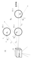
- FIG. 1 shows a system configuration example of the present disclosure.
- the system of the present disclosure includes a point cloud data generation device 91 , a point cloud measuring instrument 92 , a measurement object 93 , and a correction data acquisition object 95 .
- the point cloud data generation device 91 includes a correct data point cloud generation function unit 11 , a correction data generation function unit 12 , and a storage unit 13 .
- the device of the present disclosure can also be implemented by a computer and a program, and the program can be recorded on a recording medium or provided through a network.
- This disclosure is A method for creating correct data used in machine learning for modeling based on measured point cloud data, Correction point cloud data 22 obtained by measuring a known shape correction data acquisition object 95 with a point cloud measuring instrument 92, and installation of the point cloud measuring instrument 92 and the correction data acquisition object 95 when measuring the correction point cloud data 22 Using the position, calculate the correction data 23 according to the relative position of the correction data acquisition object 95 and the point cloud measuring device 92, Using the 3D CAD data 21 simulating the measurement object 93, the ideal point cloud coordinates C obtained when the measurement object 93 is measured by the point cloud measuring instrument 92 are calculated, A correction value according to the relative position of the measurement object 93 and the point cloud measuring instrument 92 used when calculating the point cloud coordinates C is extracted from the correction data 23, By correcting the ideal point cloud coordinates C of the measuring object 93 using the extracted correction values, the corrected point cloud coordinates D are calculated, and correct point cloud data simulating the measuring object 93 is generated.
- the storage unit 13 stores a point cloud measurement method 24 and a point cloud measuring instrument installation position 25 .
- the point cloud measurement method 24 is data for setting the point cloud measurement method (laser emission method, etc.) 24 of the point cloud measuring device 92 .
- the point group measurement method is, for example, a method by which the point group measuring instrument 92 acquires the point group coordinates A, and can be exemplified by, for example, a laser emission method.
- the point cloud measuring instrument installation position 25 is data for setting the installation position of the point cloud measuring instrument 92 .
- the installation position includes installation position coordinates where the point group measuring instrument 92 was installed when the point group of the correction data acquisition object 95 was measured.
- the 3D CAD data 21 is simulated data simulating the object 93 to be measured.
- the measurement object 93 is an arbitrary object to be modeled, and for example, a utility pole or a steel tower can be exemplified.
- the correction data generation function unit 12 uses the point cloud measuring instrument 92 to obtain a plurality of patterns of point clouds of the correction data acquisition object 95 and acquires the correction point cloud data 22 . Then, the correction data generation function unit 12 creates correction data 23 from the correction point cloud data 22 .
- 3D CAD data 21 simulating the measurement object 93 is input to the correct data point group generation function unit 11 .
- the correct data point cloud generation function unit 11 uses the 3D CAD data 21 to calculate the ideal point cloud coordinates C obtained when the measurement object 93 is measured by the point cloud measuring device 92 . Then, the correct data point cloud generation function unit 11 creates the corrected point cloud coordinates D by adding the correction data 23 to the ideal point cloud coordinates C thus obtained. Then, the correct data point cloud generation function unit 11 outputs the corrected point cloud coordinates D as correct point cloud data.
- FIG. 2 is a flowchart showing an example of a method for creating the correction point cloud data 22 in the correction data generation function unit 12.
- Step S11 Acquire the point group coordinates A (x A , y A , z A ) of the correction data acquisition object 95 .
- Step S12 Acquire the installation position coordinates of the correction data acquisition object 95 .
- Step S13 Acquire the diameter of the object 95 for correction data acquisition.
- Step S14 Acquire the installation position coordinates (0, 0) of the point cloud measuring instrument 92 from the point cloud measuring instrument installation position 25 .
- Step S15 Using the installation position coordinates and diameter of the correction data acquisition object 95, ideal point cloud coordinates B (xB, yB , zB ) are obtained from the installation position coordinates (0, 0) of the point cloud measuring instrument 92 ) is calculated.
- Step S16 The distance L from the point group coordinates B to the point group measuring device 92 and the angle ⁇ at which the light from the point group measuring device 92 is reflected at the point group coordinates B are calculated.
- the angle ⁇ an example of an incident angle at which the light from the point group measuring device 92 is incident on the point group coordinates B will be described.
- Step S17 Coordinate errors ( ⁇ x, ⁇ y, ⁇ z) of point group coordinates A and point group coordinates B are calculated.
- ⁇ x x B ⁇ x A
- ⁇ y y B ⁇ y A
- ⁇ z z B ⁇ z A
- Step S18 Coordinate error ⁇ ( ⁇ x, ⁇ y, ⁇ z) of point cloud coordinates A and B is linked to angle ⁇ and distance L of point cloud coordinates B to create correction data.
- FIG. 3 shows an example of acquisition of correction point cloud data using the point cloud measuring instrument 92.
- the correction data acquisition object 95 is assumed to be a perfect sphere.
- the correction data acquisition object 95 is measured using the fixed point group measuring instrument 92F.
- the horizontal and vertical distances between the correction data acquiring object 95 and the fixed point group measuring instrument 92F are changed.
- the fixed point cloud measuring instrument 92F measures the correction data acquisition object 95 at distances L1, L2, and L3. Thereby, it is possible to acquire a plurality of patterns of point group coordinates A having different distances L and angles ⁇ from the correction data acquiring object 95 .
- the correction data generation function unit 12 calculates ideally obtained point group coordinates B from the obtained point group coordinates A and the diameter of the sphere. Then, the correction data generation function unit 12 calculates the distance L from the point cloud coordinates B to the point cloud measuring instrument 92F and the angle ⁇ .
- the difference between the point group coordinates A and B is derived as a coordinate error ⁇ for each (x, y, z) axis.
- the coordinate error ⁇ ( ⁇ x, ⁇ y, ⁇ z) is obtained.
- the correction data 23 is created by associating the distance and angle (L, ⁇ ) of the point cloud coordinates B with the coordinate error ⁇ .
- FIG. 4 shows an example of correction data. ⁇ x included in the correction data 23 is calculated for each combination of the distance L and the angle ⁇ . The same is true for ⁇ y and ⁇ z.
- the correction data acquisition object 95 may have the same shape as the measurement object 93, or may have a different shape.
- the correction data acquisition object 95 may be a plane plate 95P. In the case of the plane plate 95P, not only the horizontal direction shown in FIG. 5A and the vertical direction shown in FIG. is desirable. Accordingly, the coordinate error ⁇ corresponding to the angle ⁇ can be obtained more accurately.
- FIG. 6 is a flowchart showing a first method of creating the correction data 23 in the correction data generation function unit 12.
- Step S21 Obtain ⁇ x, ⁇ y, and ⁇ z for ⁇ and L N times.
- the coordinates error ⁇ for the angle ⁇ and the distance L is measured N times ( ⁇ x 1 to ⁇ x N , ⁇ y 1 to ⁇ y N , ⁇ z 1 to ⁇ z N ).
- Step S22 Create a probability distribution (frequency distribution) of the coordinate error ⁇ from ( ⁇ x 1 to ⁇ x N , ⁇ y 1 to ⁇ y N , ⁇ z 1 to ⁇ zN). For example, as shown in FIG.
- a probability distribution of ⁇ x is created for ⁇ x acquired N times.
- a probability distribution is created for ⁇ y and ⁇ z in the same manner as for ⁇ x. This generates a probability distribution of the coordinate error ⁇ .
- ⁇ x, ⁇ y, and ⁇ z are determined based on the created probability distribution. For example, ⁇ x, ⁇ y, and ⁇ z are determined as the most probable values in the probability distribution.
- Step S23 The angle ⁇ and the distance L are associated with the coordinate error ⁇ and stored as correction data.
- FIG. 8 is a flowchart showing a second method of creating the correction data 23 in the correction data generation function unit 12. As shown in FIG. This method differs from the first method in that the approximation is performed using the value of one measurement for each (L, ⁇ ), and the correction is a single value for some (L, ⁇ ).
- Step S31 A coordinate error ⁇ with respect to the angle ⁇ and the distance L is obtained.
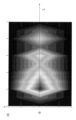
- Step S32 An approximate curved surface representing the coordinate error ⁇ with respect to the angle ⁇ and the distance L is calculated.
- FIG. 9 shows an example of an approximate curved surface.
- Step S33 Save the approximate curved surface formula for the angle ⁇ and the distance L as correction data.
- step S32 approximation may be performed for ⁇ x, ⁇ y, and ⁇ z according to ⁇ and L to uniquely determine the values. For example, the closer the value of ⁇ to 0, the smaller ⁇ x, ⁇ y, and ⁇ z, and the larger the value, the larger ⁇ x, ⁇ y, and ⁇ z. Also, the closer the value of L is to 0, the larger ⁇ x, ⁇ y, and ⁇ z. Therefore, it is desirable to decompose on the ⁇ axis and approximate L with a quadratic function or a cubic function.
- FIG. 10 is a flow chart showing an example of a method for creating the corrected point cloud coordinates D in the correct data point cloud generating function unit 11 .
- Step S41 The 3D CAD data 21 of the measurement object 93 and the installation position coordinates of the measurement object 93 are obtained.
- Step S42 The point group measuring instrument installation position 25 is acquired.
- Step S43 Acquire the laser emission method (laser emission angle) as the point group measurement method 24 of the point group measuring device 92 .
- Step S44 Using the 3D CAD data 21 of the measurement object 93, the point cloud coordinates C of the measurement object 93 that are ideally obtained when the measurement object 93 is measured by the point cloud measuring instrument 92 are calculated. At this time, using the point cloud measuring device installation position 25 and the point cloud measuring method 24, the relative positions of the measurement object 93 and the point cloud measuring device 92 when the correction point cloud data 22 is acquired are included. . Step S45: Using the installation position coordinates of the measurement object 93, the installation position coordinates 25 of the point cloud measuring instrument 92, and the point cloud measurement method 24, the angle ⁇ and the distance L at each point cloud coordinate C are calculated.
- Step S46 Acquire the correction data 23 .
- Step S47 Coordinate error ⁇ ( ⁇ x, ⁇ y, ⁇ z) at angle ⁇ and distance L is calculated from correction data 23 .
- the coordinate error ⁇ ( ⁇ x, ⁇ y, ⁇ z) corresponding to (La, ⁇ a) is extracted from the correction data 23 .
- Step S48 As shown in FIG. 12, a coordinate error .DELTA.(.DELTA.x, .DELTA.y, .DELTA.z) is added to the point cloud coordinates C to calculate the corrected point cloud coordinates D.
- Step S49 Output the corrected point cloud coordinates D to the outside as correct point cloud data.
- step S45 for example, when the point cloud measurement method is by emitting laser light, the distance and angle ⁇ in the point cloud coordinates Ca are (La, ⁇ a), as shown in FIG.
- the coordinate error ⁇ corresponding to (La, ⁇ a) is extracted from the correction data 23 (S47), and the extracted coordinate error ⁇ is added to the point cloud coordinates Ca.
- the corrected point cloud coordinates D obtained by correcting the point cloud coordinates Ca can be calculated.
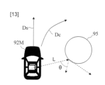
- the point group measuring instrument 92 is a mobile point group measuring instrument 92M such as MMS
- 13 and 14 show examples of acquisition of the correction point cloud data 22 using the mobile point cloud measuring instrument 92M.
- the correction data acquisition object 95 is assumed to be a perfect sphere.
- step S11 shown in FIG. 2 the mobile point cloud measuring instrument 92M is used to measure the correction data acquisition object 95 in order to acquire the point cloud coordinates A.
- the measurement (running) direction of the mobile point group measuring device 92M with respect to the correction data acquisition object 95 is acquired in two patterns of a straight line Dc and a curve Dc.
- the measurement (running) direction of the mobile point cloud measuring instrument 92M can be any number of patterns equal to or greater than two.
- the curvature of the curve Dc may be obtained by further subdividing it.
- two or more patterns of correction data acquisition objects such as correction data acquisition objects 95-1 and 95-2 can be obtained.
- the installation position coordinates of the correction data acquisition object 95 may be subdivided and acquired.
- the traveling position of the mobile point group measuring device 92M may be changed.
- the installation position coordinates of the correction data acquisition object 95 and the diameter of the sphere are acquired in advance (S12 to S14).
- point group coordinates B ideally obtained in each measurement direction are calculated using the installation position coordinates of the correction data acquisition object 95 and the diameter of the sphere. For example, point group coordinates B (x B , y B , z B ) are calculated for each of straight line Dc and curve Dc.
- step S16 the distance L and the angle ⁇ from the point cloud coordinates B to the point cloud measuring instrument 92 are calculated for each measurement direction.
- step S17 a coordinate error ⁇ ( ⁇ x, ⁇ y, ⁇ z) between the point group coordinates A and B is calculated for each measurement direction.
- step S18 the coordinate error ⁇ ( ⁇ x, ⁇ y, ⁇ z) is linked to the distance L and the angle ⁇ of the point group coordinates B to create the correction data 23 .
- correction data 23 is created for each measurement direction.
- the correction data acquisition object 95 is made of the same material as the measurement object 93 . Further, the correction data acquisition object 95 may be a plane plate 95P as shown in FIGS. 5(a) and 5(b).
- correction data generation function unit 12 A first method for creating the correction data 23 in the correction data generation function unit 12 will be described. Also in this embodiment, steps S21 to S23 are executed as in the first embodiment. At this time, each step is executed for each measurement direction executed in step S11. Thereby, correction data in which the probability distribution of the coordinate error ⁇ is associated with the distance L and the angle ⁇ is generated for each measurement direction.
- the correction data generation function unit 12 may generate correction data using the second generation method shown in FIG. This allows an approximation to be made using the value of a single measurement for each (L, ⁇ ) and the correction to a single value for some (L, ⁇ ).
- the distance L and the angle ⁇ in the point cloud coordinates C are calculated (S45). For example, as shown in FIG. 15, the distance and angle (La, ⁇ a) in point group coordinates Ca and the distance and angle (Lb, ⁇ b) in point group coordinates Cb are calculated.
- the coordinate error ⁇ ( ⁇ x, ⁇ y, ⁇ z) at the point group coordinates Ca is obtained from (La, ⁇ a) (S47). Then, as shown in FIG. 12, a coordinate error ⁇ ( ⁇ x, ⁇ y, ⁇ z) corresponding to (La, ⁇ a) is added to the point cloud coordinates Ca to obtain corrected point cloud coordinates at the point cloud coordinates Ca. Da is calculated (S48). This processing is performed for all the point group coordinates C.
- correction data in which the angle ⁇ , the distance L, and the probability distribution of the coordinate error ⁇ are linked is generated for each measurement direction. Therefore, in this embodiment, the corrected point cloud coordinates D are calculated for each measurement direction. For example, if the measurement direction is the straight line Ds, the straight line correction coordinates are used, and if the measurement direction is the curve Dc, the curve correction coordinates are used. Finally, the corrected point cloud coordinates D are output for each measurement direction and stored as a correct data point cloud (S49).
- the correct data generation device 91 of the present embodiment includes the correct data point cloud generation function unit 11, so that the correction data 23 can be used to automatically generate correct point cloud data.
- the correct data generation device 91 of the present embodiment it becomes unnecessary to manually create correct data from the point cloud, and the work time for manually creating correct data can be reduced.
- the correct data generation device 91 of the present embodiment corrects the point cloud coordinates C using the coordinate error ⁇ according to the angle ⁇ and the distance L, the actual data considering the measurement error of the point cloud measuring device 92 Close simulation data is possible.
- correct data can be created even if the measurement object 93 is not present in the actual equipment.
- the present embodiment enables reproduction of actual equipment using 3D CAD, and generation of correct data for machine learning by point cloud simulation in consideration of measurement errors of the point cloud measuring device 92 .
- This disclosure can be applied to the information and communications industry.
Landscapes
- Engineering & Computer Science (AREA)
- Physics & Mathematics (AREA)
- Theoretical Computer Science (AREA)
- General Physics & Mathematics (AREA)
- Geometry (AREA)
- Evolutionary Computation (AREA)
- Computer Hardware Design (AREA)
- General Engineering & Computer Science (AREA)
- Pure & Applied Mathematics (AREA)
- Mathematical Optimization (AREA)
- Mathematical Analysis (AREA)
- Computational Mathematics (AREA)
- Length Measuring Devices With Unspecified Measuring Means (AREA)
- Length Measuring Devices By Optical Means (AREA)
Priority Applications (3)
| Application Number | Priority Date | Filing Date | Title |
|---|---|---|---|
| JP2023537767A JP7670136B2 (ja) | 2021-07-26 | 2021-07-26 | 点群データを生成する装置、方法及びプログラム |
| PCT/JP2021/027596 WO2023007559A1 (ja) | 2021-07-26 | 2021-07-26 | 点群データを生成する装置、方法及びプログラム |
| US18/576,083 US20240330537A1 (en) | 2021-07-26 | 2021-07-26 | Device, method and program for generating point cloud data |
Applications Claiming Priority (1)
| Application Number | Priority Date | Filing Date | Title |
|---|---|---|---|
| PCT/JP2021/027596 WO2023007559A1 (ja) | 2021-07-26 | 2021-07-26 | 点群データを生成する装置、方法及びプログラム |
Publications (1)
| Publication Number | Publication Date |
|---|---|
| WO2023007559A1 true WO2023007559A1 (ja) | 2023-02-02 |
Family
ID=85086391
Family Applications (1)
| Application Number | Title | Priority Date | Filing Date |
|---|---|---|---|
| PCT/JP2021/027596 Ceased WO2023007559A1 (ja) | 2021-07-26 | 2021-07-26 | 点群データを生成する装置、方法及びプログラム |
Country Status (3)
| Country | Link |
|---|---|
| US (1) | US20240330537A1 (https=) |
| JP (1) | JP7670136B2 (https=) |
| WO (1) | WO2023007559A1 (https=) |
Citations (2)
| Publication number | Priority date | Publication date | Assignee | Title |
|---|---|---|---|---|
| WO2019138677A1 (ja) * | 2018-01-15 | 2019-07-18 | キヤノン株式会社 | 情報処理装置及びその制御方法及びコンピュータ可読記憶媒体、並びに、運転制御システム |
| JP2021060199A (ja) * | 2019-10-02 | 2021-04-15 | 株式会社大林組 | 鉄筋推定システム、鉄筋推定方法及び鉄筋推定プログラム |
-
2021
- 2021-07-26 WO PCT/JP2021/027596 patent/WO2023007559A1/ja not_active Ceased
- 2021-07-26 US US18/576,083 patent/US20240330537A1/en active Pending
- 2021-07-26 JP JP2023537767A patent/JP7670136B2/ja active Active
Patent Citations (2)
| Publication number | Priority date | Publication date | Assignee | Title |
|---|---|---|---|---|
| WO2019138677A1 (ja) * | 2018-01-15 | 2019-07-18 | キヤノン株式会社 | 情報処理装置及びその制御方法及びコンピュータ可読記憶媒体、並びに、運転制御システム |
| JP2021060199A (ja) * | 2019-10-02 | 2021-04-15 | 株式会社大林組 | 鉄筋推定システム、鉄筋推定方法及び鉄筋推定プログラム |
Also Published As
| Publication number | Publication date |
|---|---|
| JP7670136B2 (ja) | 2025-04-30 |
| JPWO2023007559A1 (https=) | 2023-02-02 |
| US20240330537A1 (en) | 2024-10-03 |
Similar Documents
| Publication | Publication Date | Title |
|---|---|---|
| JP5350729B2 (ja) | 出来型確認システムおよび出来型確認プログラム、並びに出来型確認方法 | |
| CN104899378A (zh) | 基于bim和三维测量的高层钢结构数字化安装方法 | |
| CN110060342B (zh) | 一种三维曲面拟合方法 | |
| CN110706331A (zh) | 一种基于bim点云技术与三维扫描的施工质量控制方法 | |
| CN110290463A (zh) | 基于最优化理论的uwb基站坐标自动标定方法和系统 | |
| CN116151628B (zh) | 隧道施工中地面沉降的监测与预警系统 | |
| CN113536412A (zh) | 一种基于bim和gis的三维实景模型高精度融合方法 | |
| CN115509176A (zh) | 一种基于在机测量的曲面随形补偿加工系统以及加工方法 | |
| CN105279371B (zh) | 一种基于控制点的移动测量系统pos精度改善方法 | |
| CN114777687A (zh) | 基于概率分布函数的分区域相位误差补偿方法及设备 | |
| WO2023007559A1 (ja) | 点群データを生成する装置、方法及びプログラム | |
| KR20060100157A (ko) | 공간정보/위치정보의 정밀 위치정보 변환을 위한 변동량모델링 방법 | |
| CN118115688B (zh) | 一种用于无人驾驶矿车的矿洞三维地图构建方法及系统 | |
| CN108875139A (zh) | 一种基于现实环境的三维布置方法和系统 | |
| CN113515513B (zh) | 轨迹矫正方法及装置、点云地图生成方法及装置 | |
| CN118036140A (zh) | 矿井巷道的三维模型的构建方法、装置、介质和电子设备 | |
| KR20030036988A (ko) | 영상 매칭을 위한 파라메터 변환 장치 및 그 방법 | |
| CN115713607A (zh) | 基于激光雷达和倾斜摄影提升建模质量的方法 | |
| Lichti et al. | Observation distribution modelling and closed-from precision estimation of scanned 2D geometric features for network design | |
| CN109858149B (zh) | 海上勘探井点快速定位方法和装置、电子设备、存储介质 | |
| CN111366172A (zh) | 数字高程模型的质量检测方法、装置和存储介质 | |
| NL2030845B1 (en) | Positioning and correction method and system of video data using seabed topographic profile | |
| JP7563498B2 (ja) | 3d点群の座標を変換する装置、方法及びプログラム | |
| CN113518358B (zh) | 一种无线传感器网络布测位置误差的校正方法和装置 | |
| WO2025211016A1 (ja) | 管路推定システム、管路推定方法、および管路推定プログラム |
Legal Events
| Date | Code | Title | Description |
|---|---|---|---|
| 121 | Ep: the epo has been informed by wipo that ep was designated in this application |
Ref document number: 21951770 Country of ref document: EP Kind code of ref document: A1 |
|
| WWE | Wipo information: entry into national phase |
Ref document number: 2023537767 Country of ref document: JP |
|
| WWE | Wipo information: entry into national phase |
Ref document number: 18576083 Country of ref document: US |
|
| NENP | Non-entry into the national phase |
Ref country code: DE |
|
| 122 | Ep: pct application non-entry in european phase |
Ref document number: 21951770 Country of ref document: EP Kind code of ref document: A1 |