WO2023002892A1 - 生体分子を検出する方法及び装置 - Google Patents
生体分子を検出する方法及び装置 Download PDFInfo
- Publication number
- WO2023002892A1 WO2023002892A1 PCT/JP2022/027516 JP2022027516W WO2023002892A1 WO 2023002892 A1 WO2023002892 A1 WO 2023002892A1 JP 2022027516 W JP2022027516 W JP 2022027516W WO 2023002892 A1 WO2023002892 A1 WO 2023002892A1
- Authority
- WO
- WIPO (PCT)
- Prior art keywords
- electrode
- aptamer
- protein
- biomolecule
- mediator
- Prior art date
- Legal status (The legal status is an assumption and is not a legal conclusion. Google has not performed a legal analysis and makes no representation as to the accuracy of the status listed.)
- Ceased
Links
Images


Classifications
-
- G—PHYSICS
- G01—MEASURING; TESTING
- G01N—INVESTIGATING OR ANALYSING MATERIALS BY DETERMINING THEIR CHEMICAL OR PHYSICAL PROPERTIES
- G01N33/00—Investigating or analysing materials by specific methods not covered by groups G01N1/00 - G01N31/00
- G01N33/48—Biological material, e.g. blood, urine; Haemocytometers
- G01N33/50—Chemical analysis of biological material, e.g. blood, urine; Testing involving biospecific ligand binding methods; Immunological testing
- G01N33/53—Immunoassay; Biospecific binding assay; Materials therefor
- G01N33/543—Immunoassay; Biospecific binding assay; Materials therefor with an insoluble carrier for immobilising immunochemicals
- G01N33/54366—Apparatus specially adapted for solid-phase testing
- G01N33/54373—Apparatus specially adapted for solid-phase testing involving physiochemical end-point determination, e.g. wave-guides, FETS, gratings
- G01N33/5438—Electrodes
-
- G—PHYSICS
- G01—MEASURING; TESTING
- G01N—INVESTIGATING OR ANALYSING MATERIALS BY DETERMINING THEIR CHEMICAL OR PHYSICAL PROPERTIES
- G01N27/00—Investigating or analysing materials by the use of electric, electrochemical, or magnetic means
- G01N27/02—Investigating or analysing materials by the use of electric, electrochemical, or magnetic means by investigating impedance
- G01N27/026—Dielectric impedance spectroscopy
-
- G—PHYSICS
- G01—MEASURING; TESTING
- G01N—INVESTIGATING OR ANALYSING MATERIALS BY DETERMINING THEIR CHEMICAL OR PHYSICAL PROPERTIES
- G01N27/00—Investigating or analysing materials by the use of electric, electrochemical, or magnetic means
- G01N27/02—Investigating or analysing materials by the use of electric, electrochemical, or magnetic means by investigating impedance
- G01N27/22—Investigating or analysing materials by the use of electric, electrochemical, or magnetic means by investigating impedance by investigating capacitance
- G01N27/226—Construction of measuring vessels; Electrodes therefor
-
- G—PHYSICS
- G01—MEASURING; TESTING
- G01N—INVESTIGATING OR ANALYSING MATERIALS BY DETERMINING THEIR CHEMICAL OR PHYSICAL PROPERTIES
- G01N27/00—Investigating or analysing materials by the use of electric, electrochemical, or magnetic means
- G01N27/26—Investigating or analysing materials by the use of electric, electrochemical, or magnetic means by investigating electrochemical variables; by using electrolysis or electrophoresis
- G01N27/28—Electrolytic cell components
- G01N27/30—Electrodes, e.g. test electrodes; Half-cells
- G01N27/327—Biochemical electrodes, e.g. electrical or mechanical details for in vitro measurements
- G01N27/3275—Sensing specific biomolecules, e.g. nucleic acid strands, based on an electrode surface reaction
- G01N27/3276—Sensing specific biomolecules, e.g. nucleic acid strands, based on an electrode surface reaction being a hybridisation with immobilised receptors
-
- G—PHYSICS
- G01—MEASURING; TESTING
- G01N—INVESTIGATING OR ANALYSING MATERIALS BY DETERMINING THEIR CHEMICAL OR PHYSICAL PROPERTIES
- G01N33/00—Investigating or analysing materials by specific methods not covered by groups G01N1/00 - G01N31/00
- G01N33/48—Biological material, e.g. blood, urine; Haemocytometers
- G01N33/483—Physical analysis of biological material
-
- G—PHYSICS
- G01—MEASURING; TESTING
- G01N—INVESTIGATING OR ANALYSING MATERIALS BY DETERMINING THEIR CHEMICAL OR PHYSICAL PROPERTIES
- G01N33/00—Investigating or analysing materials by specific methods not covered by groups G01N1/00 - G01N31/00
- G01N33/48—Biological material, e.g. blood, urine; Haemocytometers
- G01N33/50—Chemical analysis of biological material, e.g. blood, urine; Testing involving biospecific ligand binding methods; Immunological testing
- G01N33/53—Immunoassay; Biospecific binding assay; Materials therefor
- G01N33/5308—Immunoassay; Biospecific binding assay; Materials therefor for analytes not provided for elsewhere, e.g. nucleic acids, uric acid, worms, mites
-
- G—PHYSICS
- G01—MEASURING; TESTING
- G01N—INVESTIGATING OR ANALYSING MATERIALS BY DETERMINING THEIR CHEMICAL OR PHYSICAL PROPERTIES
- G01N33/00—Investigating or analysing materials by specific methods not covered by groups G01N1/00 - G01N31/00
- G01N33/48—Biological material, e.g. blood, urine; Haemocytometers
- G01N33/50—Chemical analysis of biological material, e.g. blood, urine; Testing involving biospecific ligand binding methods; Immunological testing
- G01N33/53—Immunoassay; Biospecific binding assay; Materials therefor
- G01N33/543—Immunoassay; Biospecific binding assay; Materials therefor with an insoluble carrier for immobilising immunochemicals
- G01N33/54393—Improving reaction conditions or stability, e.g. by coating or irradiation of surface, by reduction of non-specific binding, by promotion of specific binding
-
- G—PHYSICS
- G01—MEASURING; TESTING
- G01N—INVESTIGATING OR ANALYSING MATERIALS BY DETERMINING THEIR CHEMICAL OR PHYSICAL PROPERTIES
- G01N2333/00—Assays involving biological materials from specific organisms or of a specific nature
- G01N2333/435—Assays involving biological materials from specific organisms or of a specific nature from animals; from humans
- G01N2333/76—Assays involving albumins other than in routine use for blocking surfaces or for anchoring haptens during immunisation
- G01N2333/765—Serum albumin, e.g. HSA
-
- G—PHYSICS
- G01—MEASURING; TESTING
- G01N—INVESTIGATING OR ANALYSING MATERIALS BY DETERMINING THEIR CHEMICAL OR PHYSICAL PROPERTIES
- G01N2440/00—Post-translational modifications [PTMs] in chemical analysis of biological material
- G01N2440/38—Post-translational modifications [PTMs] in chemical analysis of biological material addition of carbohydrates, e.g. glycosylation, glycation
-
- G—PHYSICS
- G01—MEASURING; TESTING
- G01N—INVESTIGATING OR ANALYSING MATERIALS BY DETERMINING THEIR CHEMICAL OR PHYSICAL PROPERTIES
- G01N2600/00—Assays involving molecular imprinted polymers/polymers created around a molecular template
Definitions
- the present disclosure relates to methods and devices for detecting biomolecules.
- biosensing there is a demand for technology that more accurately and/or simply determines the amount or presence of biomolecules in solutions such as body fluids. They are also useful for point-of-care testing. They are also desired for inspection of minute amounts of specimens.
- biomolecules to be measured among various substances eg, proteins, etc.
- a method of detecting a biomolecule comprises providing an electrode and an aptamer that specifically binds to a biomolecule of interest positioned in proximity to the electrode.
- the method comprises introducing a cationic mediator to said electrode on which said aptamer is disposed.
- the method comprises contacting the aptamer with a solution containing the biomolecule of interest to allow the aptamer to bind to the biomolecule.
- the method comprises measuring electrical signals generated at the electrode due to the cationic mediator.
- the amount of biomolecules in bodily fluids can be accurately specified.
- FIG. 1 schematically shows a cross-sectional view of a biomolecule detection device according to an embodiment
- FIG. 1 schematically shows a cross-sectional view of a biomolecule detection device according to an embodiment
- FIG. 1 schematically shows a cross-sectional view of a biomolecule detection device according to an embodiment
- FIG. 1 schematically shows a cross-sectional view of a biomolecule detection device according to an embodiment
- FIG. 1 schematically shows a cross-sectional view of a biomolecule detection device according to an embodiment
- FIG. 1 schematically shows a cross-sectional view of a biomolecule detection device according to an embodiment
- FIG. FIG. 4 shows a Nyquist plot from electrochemical impedance spectroscopy obtained in a measurement according to an embodiment
- FIG. FIG. 4 shows a Nyquist plot from electrochemical impedance spectroscopy obtained in a measurement according to an embodiment
- FIG. FIG. 4 shows a Nyquist plot from electrochemical impedance spectroscopy obtained in a measurement according to
- FIG. 4 shows a Nyquist plot from electrochemical impedance spectroscopy obtained in a measurement according to an embodiment
- FIG. FIG. 4B shows a graph showing the relationship between detection output and concentration obtained from the measurement results shown in FIGS. 4A and 4B.
- FIG. 1 schematically shows a cross-sectional view of a biomolecule detection device according to an embodiment
- FIG. 1 schematically shows a cross-sectional view of a biomolecule detection device according to an embodiment
- FIG. FIG. 4 shows a Nyquist plot from electrochemical impedance spectroscopy obtained in a measurement according to an embodiment
- FIG. FIG. 4 shows a Nyquist plot from electrochemical impedance spectroscopy obtained in a measurement according to an embodiment
- FIG. 4 shows a Nyquist plot from electrochemical impedance spectroscopy obtained in a measurement according to an embodiment
- FIG. 4 shows a Nyquist plot from electrochemical impedance spectroscopy, according to an embodiment.
- FIG. 4 shows a graph of detected output versus concentration obtained from measurements according to an embodiment;
- FIG. 1 schematically shows a cross-sectional view of a biomolecule detection device according to an embodiment;
- FIG. 1 schematically shows a cross-sectional view of a biomolecule detection device according to an embodiment;
- FIG. 1 schematically shows a cross-sectional view of a biomolecule detection device according to an embodiment;
- FIG. 1 schematically shows a cross-sectional view of a biomolecule detection device according to an embodiment;
- FIG. FIG. 4 shows a Nyquist plot from electrochemical impedance spectroscopy obtained in a measurement according to an embodiment;
- FIG. FIG. 4 shows a Nyquist plot from electrochemical impedance spectroscopy obtained in a measurement according to an embodiment;
- FIG. FIG. 4 shows a Nyquist plot from electrochemical impedance spectroscopy obtained
- FIG. 4 shows a Nyquist plot from electrochemical impedance spectroscopy obtained in a measurement according to an embodiment
- FIG. 4 shows a graph of detected output versus concentration obtained from measurements according to an embodiment
- FIG. 1 shows a flowchart of a method for measuring biomolecules, according to an embodiment. 1 shows a flowchart of a method for measuring biomolecules, according to an embodiment.
- Biomolecule generally refers to biological molecules, molecules that exist or function in vivo.
- Biomolecules include, without limitation, proteins, oligonucleotides, nucleic acids (DNA, RNA), amino acids, peptides, lipids, cells, vesicles, sugars, carbohydrates, antibodies, and modified or altered substances thereof.
- Proteins as target biomolecules include, but are not limited to, albumin and hemoglobin.
- the biomolecule of interest may be glucose.
- Other biomolecules of interest include, but are not limited to, neurotransmitters such as dopamine, metabolites, diabetes markers, cancer markers, allergy-related substances such as histamine, Alzheimer-related substances such as amyloid ⁇ , and the like.
- biomolecules include, for example and without limitation, biomolecules such as nucleic acids and proteins derived from bacteria or viruses.
- Viruses include, for example, without limitation, influenza virus, ronavirus, norovirus, Ebola virus, and the like.
- biomolecules comprise extracellular vesicles.
- An extracellular vesicle (EV) may be an exosome.
- biomolecules of interest include glycated biomolecules.
- the biomolecule of interest may be a glycated protein.
- the biomolecule of interest may be glycoalbumin.
- Biomolecules of interest include, but are not limited to, glycated hemoglobin (HbA1c); glycated proteins containing sialic acid and related glycopeptides that are abundantly expressed on cancer cell surfaces; and N ⁇ -carboxymethyllysine (CML), N ⁇ - Carboxyethyllysine (CEL), argupyrimidine, pentosidine, pyraline, crossrin, GA-pyridine, N ⁇ -carboxymethylarginine (CMA), furoylfuranilimidazole, advanced glycation end products (AGEs) including glucospan, and the like.
- HbA1c glycated hemoglobin
- CML N ⁇ -carboxymethyllysine
- CEL N ⁇ - Carboxyethyllysine
- argupyrimidine pentosidine, pyraline, crossrin, GA-pyridine, N ⁇ -carboxymethylarginine (CMA), furoylfuranilimi
- the biomolecules of interest may comprise multiple types of biomolecules of interest.
- Biomolecules may be naturally produced or artificially produced.
- the target biomolecule may be provided in a liquid (solution).
- the liquid may be a bodily fluid secreted from the subject or a liquid other than the bodily fluid.
- the liquid other than the bodily fluid may be a liquid adhering to the subject or a liquid not adhering to the subject.
- the liquid not adhering to the subject may be liquid contained in the subject.
- the provided liquid may contain or possibly contain the target biomolecule, or may be a reference liquid used to measure the target biomolecule.
- the liquid (or solution) containing the target biomolecules may be referred to as including these cases.
- the liquid containing the target biomolecules may be a solution.
- the liquid may be a body fluid, a solution derived from the body fluid, or a diluted solution of the body fluid.
- the liquid may be a solution that is not a bodily fluid (derived from a non-bodily fluid), or a mixture of a bodily fluid or a bodily fluid-derived solution and a non-bodily fluid-derived solution.
- the solution may be the solution used for sample measurements or the solution used for calibration measurements.
- the solution may be a standard solution or a calibrator solution.
- the sample to be measured may be a specimen.
- the body fluid may be lymph, interstitial fluid such as interstitial fluid, intercellular fluid, interstitial fluid, body cavity fluid, serous fluid, pleural fluid, ascites, pericardial fluid, cerebrospinal fluid (cerebrospinal fluid). ), synovial fluid (synovial fluid), aqueous humor (aqueous humor).
- the bodily fluid may be a digestive fluid such as saliva, gastric juice, bile, pancreatic juice, intestinal juice, sweat, tears, runny nose, urine, semen, vaginal fluid, amniotic fluid, milk.
- the bodily fluid may be an animal bodily fluid or a human bodily fluid.
- a "bodily fluid" may be a solution.
- the solutions include phosphate buffered saline (PBS), N-tris(hydroxymethyl)methyl-2-aminoethanesulfonic acid buffer (TES), hydroxyethylpiperazine ethanesulfonic acid buffer (HEPES ) and other physiological buffers.
- PBS phosphate buffered saline
- TES N-tris(hydroxymethyl)methyl-2-aminoethanesulfonic acid buffer
- HPES hydroxyethylpiperazine ethanesulfonic acid buffer
- the solution is not particularly limited as long as it contains the substance to be measured.
- the bodily fluid may be blood.
- blood may be drawn.
- blood may be collected at the same time as the puncture bleeding.
- blood may be needled and aspirated.
- a puncture device eg, needle, hypodermic needle, etc.; hereinafter the same
- the capillary tube may be configured as a piercer.
- the subject may include humans or may be humans. In some embodiments, the subject may include non-human animals and may be non-human animals. Non-human animals may include mammals and may be mammals. Non-human animals can be, for example, without limitation, working animals, livestock animals, companion animals, wild animals.
- electrodes may be used for electrochemical measurements.
- the electrodes may be made of a conductive material.
- the electrodes may be made of metal.
- the electrodes may be made of, for example and without limitation, metal materials such as gold (Au), platinum (Pt), palladium (Pd), and the like.
- the electrodes may be made of non-metallic materials.
- the electrodes may be made of carbon (C).
- the electrodes may be made of graphene, carbon nanotubes, or the like.
- the electrodes may be connected or configured to be connected to a meter, measuring device or measuring element.
- the electrodes may be connected to an impedance meter.
- electrical signals at the electrodes may be detected or analyzed using electrochemical impedance spectroscopy (EIS). Cole-Cole plots or Nyquist plots may thereby be generated. A capacitive component of the measurement system may be determined or analyzed.
- electrical signals at the electrodes may be detected or analyzed using cyclic voltammetry (CV).
- the electrode near the aptamer may be used as the working electrode (WE).
- WE working electrode
- a counter electrode (CE) as well as a reference electrode (RE) may be arranged.
- the electrodes may be connected to ammeters, ammeters, amperometers, or the like.
- the electrical signal at the electrodes may be amperometrically measured or analyzed.
- the electrodes may be connected to voltmeters, potentiometers, transistors (eg, field effect transistors), and the like.
- the electrical signal at the electrodes may be measured or analyzed potentiometrically.
- a device or apparatus may comprise multiple electrodes.
- multiple electrodes may have the same aptamer.
- at least some or all of the multiple electrodes may have aptamers that are different from each other. This allows, for example, different biomolecules to be detected or measured on one device.
- at least some or all of the multiple electrodes may have different densities of aptamers from each other. Accordingly, for example, appropriate measurements can be performed in different concentration ranges.
- a device or apparatus may comprise multiple electrodes arranged in an array. This allows, for example, sensor integration. Alternatively, for example, the two-dimensional or spatial distribution of the introduced biomolecule or its reaction with an aptamer or the like, or its temporal change can be measured or observed.
- the device or apparatus comprises multiple electrodes, some of which may have sensing configurations other than aptamer use. In some embodiments, the device or apparatus comprises multiple electrodes, some of which may have aptamers, and some or all of which may have other sensing configurations. For example, some of the multiple electrodes may have a sensing configuration that recognizes a biomolecule different from the target biomolecule of the aptamer. For example, the electrodes may have antibodies that recognize specific biomolecules.
- aptamer is used interchangeably with the term “nucleic acid ligand” and refers to a DNA, RNA, oligonucleotide or peptide molecule that binds to a specific target molecule. Aptamers may be single-stranded. Aptamers are generally relatively inexpensive and have long lifetimes.
- the aptamer may be placed near the electrode. In some embodiments, aptamers may be immobilized relative to electrodes. The aptamer may be directly immobilized to the electrode, or indirectly immobilized to the electrode via another substance. In some embodiments, aptamers may not be immobilized to electrodes.
- an anchor layer may be formed on the surface of the electrode and the aptamer may be fixed to the anchor layer, or the aptamer may be synthesized using the anchor layer as a scaffold.
- the anchor layer may be formed as a protective coating as described in this disclosure. That is, the anchor layer and the protective film may be defined as the same member. In some embodiments, the anchor layer may be placed in addition to the protective film and formed above (opposite the electrode) or below (between the electrode and the protective film) the protective film as viewed from the electrode. good too.
- an aptamer may be an aptamer that specifically binds to a protein. Aptamers may be single-stranded. In some embodiments, the aptamer may be an aptamer that specifically binds to glycoalbumin.
- the base sequences constituting the aptamers may be as follows (Table 1). 5′-TGCGGTTGTAGTACTCGTGGCCG-3′ (SEQ ID NO: 1)
- the biomolecule to which the aptamer specifically binds may be a cell surface-expressed protein or a cell surface membrane protein.
- the aptamer may be an aptamer that specifically binds to a membrane protein on the surface of leukemic cancer cells, and the base sequence that constitutes the aptamer may be the following (Table 1). 5′-AAAAAAAAAAAATCTAACTGCTGCGCCGCCGGGAAAATACTGTACGGTTAGA-3′ (SEQ ID NO: 2)
- a virus may be, for example, without limitation, a coronavirus.
- the coronavirus may be, for example and without limitation, the SARS virus.
- the coronavirus may be the SARS-C coronavirus OVID-19 virus.
- the base sequences constituting the aptamers may be as follows (Table 1).
- Aptamers are not limited to one or more nucleotide sequences selected from SEQ ID NO: 1 to 5 above, and may contain other nucleotide sequences or may be aptamers that recognize other biomolecules.
- a “mediator” as used herein may have an opposite charge to the aptamer.
- cationic mediator refers to a mediator that has a positive charge or is positively charged and that can be used in electrochemical measurements.
- nucleic acids that constitute aptamers generally have a negative charge.
- Cationic mediators may be complexes with cationic ligands.
- Cationic mediators may be, for example, ruthenium complexes (also referred to as “complex ions”).
- the ruthenium complex can be a ruthenium (II) complex.
- the ruthenium complex may be, for example, [Ru( NH3 ) 6 ] 2+ .
- Cationic mediators may be, for example, osmium complexes.
- the osmium complex can be an osmium (II) complex.
- the osmium complex can be a cobalt (II) complex ([Co(bpy) 3 ] 3+ /2 + , [Co(phen) 3 ] 3+ /2 + , etc.).
- the mediator may be provided in a solution.
- the mediator may be dissolved or contained in water, for example.
- the mediator solution may be a buffered solution such as, for example and without limitation, phosphate buffered saline (PBS).
- PBS phosphate buffered saline
- a protective film or protective layer may be arranged on the surface of the electrode.
- the protective film substantially prevents substances (such as contaminants) that affect the measurement of the object from reaching, contacting, approaching, adsorbing, and chemically or electrically affecting the electrode. It may have the ability to avoid or reduce its effects.
- the protective film may be made of an organic substance, an inorganic substance, or a mixture thereof. In some embodiments, the protective film may be substantially made of a polymer.
- the protective film may have the ability to allow the mediator to pass through sufficiently for measurement by the electrode.
- the protective membrane may have the ability to block or restrict the penetration of contaminants.
- the protective film may be an aryl-based single layer film or multilayer film.
- Aryl-based membranes may be formed using an electrochemical grafting process.
- a diazonium molecule may also be used.
- the diazonium molecule can be, for example, a 4-nitrobenzene diazonium salt.
- Aryl-based films may be formed using cyclic voltammetry (CV).
- the aryl-based film may be formed using a radical scavenger (also called a radical scavenger or radical scavenger).
- a radical scavenger may be, for example and without limitation, 2,2-diphenyl-1-picrylhydrazyl (DPPH).
- DPPH 2,2-diphenyl-1-picrylhydrazyl
- a radical scavenger may be used to form a monolayer film. Diazonium radicals electrochemically generated from diazonium molecules bind to the surface of an electrode (eg Au) in the presence of a radical scavenger. Thereby, a relatively dense film can be formed. The higher the surface coverage of the grafted monolayer, the more inhibited the redox reaction between the molecule and the electrode surface. For example, a monomolecular layer may be formed to a density that permits permeation of the mediator.
- a multi-layer film can be formed by repeating electrochemical polymerization, for example, by cyclic voltammetry (CV) on a diazonium layer grafted as a monolayer film.
- CV cyclic voltammetry
- the electrically generated diazonium radicals do not react with the electrode surface, but with the grafted diazonium. Therefore, a multi-layer film can be formed by diazonium grafting without changing the density of the initial diazonium layer on the electrode surface. Therefore, this multilayer film has a certain amount of gap. It is also possible to control the thickness of the multilayer film. In this way, contaminants are prevented from approaching the electrode surface, and biomolecules with a relatively low molecular weight can reach the electrode surface through the gaps in the multilayer film.
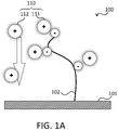
- FIG. 1A and 1B schematically show the basic configuration of the electrochemical sensor 100 when the target biomolecules are not present in the system and when the target biomolecules are present in the system, respectively.
- 1 to 1C exemplarily use glycoalbumin (GA) as the biomolecule of interest and a nucleic acid ligand that specifically binds to glycoalbumin as the aptamer, that is, an aptamer consisting of the base sequence of SEQ ID NO: 1.
- GSA Human serum albumin
- immunoglobulins eg IgG
- a sensor 100 shown in FIG. 1A includes an electrode 101 and an aptamer 102 placed on the electrode 101 and having a negative charge.
- a sensor such as sensor 100 can be manufactured, for example, in the following manner. First, an aryldiazonium salt is electrochemically fixed or electrodeposited on the surface of an electrode to obtain a multilayer film or a single layer film. Next, N-succinimidyl 3-maleimidobenzoate (MBS) (having a carboxyl group and a maleimide group at both ends, respectively) is reacted with a functional group (eg, amino group) in the multilayer film or single layer film. As a result, the carboxyl groups react with the amino groups in the multilayer film or single-layer film. Therefore, the maleimide terminus becomes a free end. Thiolated DNA (aptamers) are reacted against it. The aptamer molecule is thereby immobilized on the electrode surface.
- MMS N-succinimidyl 3-male
- the cationic mediator 110 When the cationic mediator 110 is introduced in an environment where the target substance does not exist, some of the cationic mediators 111 are electrically attracted to the oppositely charged sites of the aptamer 102 . Other cationic mediators 112 reach the electrode 101 without sensing the electrically neutralized aptamer 102 . The reached cation mediator 112 is detected as an electrical signal at the electrode 101 .
- Ruthenium complexes [Ru(NH 3 ) 6 ] 2+ may be used as cationic mediators 110, 111, 112 in FIGS. 1A-1C.
- a ruthenium complex causes an oxidation-reduction reaction represented by the following reaction formula at the electrode 101 .
- cations other than ruthenium complexes may be used as mediators.
- osmium complexes may be used.
- FIG. 1B shows the configuration when the biomolecules to be measured are present.
- Sensor 100 is similar to FIG. 1A.
- Glycoalbumin 120 the biomolecule of interest, binds to aptamer 102 when introduced into the system.
- Glycoalbumin 120 has a positive charge at lysine 121 and arginine 122 . Aptamers 102 are believed to electrically bind to these coordinates.
- the surrounding environment of aptamer 102 bound with glycoalbumin 120 is electrically neutral. Therefore, the introduced cationic mediator 113 reaches the electrode 101 without the aptamer 102 reacting.
- the cationic mediator may be introduced first to create the situation shown in FIG. 1A, and then glycoalbumin 120 may be introduced. Glycoalbumin 120 binds to aptamer 102 . As a result, cationic mediator 111 that was electrically bound to aptamer 102 is released from aptamer 102, reaches electrode 101, and can be detected.
- the number of cationic mediators that can be detected by the electrode 101 changes depending on whether the target biomolecule (glycoalbumin 120) is present (FIG. 1A) or not (FIG. 1B).
- the resistance (R) is relatively large and the capacitance (C) is small
- the resistance (R ) is small and the capacitance (C) is large.
- anions do not have the same effect as cationic mediators.
- [Fe(CN) 6 ] 4 ⁇ is frequently used as an anion mediator. It is believed that anions exert a repulsive force on aptamers, which are normally negatively charged.
- the present invention should not be construed as being limited to these mechanisms, but may be explained or interpreted by other theories or mechanisms.
- aptamers 102 of multiple molecules of the same type may be placed on electrode 101 .
- the target biomolecule glycoalbumin 120
- the ratio of aptamers 102 that react with target biomolecules 120 to the total amount of aptamers 102 placed on electrode 101 depends on the concentration of target biomolecules 120 in the solution introduced near aptamers 102 . Therefore, the electrical signal detected by the electrode 101 depends on the concentration of the biomolecule of interest 120 in the solution.
- the number or density of aptamers 102 on the electrode 101 may vary, and multiple electrodes 101 with different amounts of aptamers 102 may be provided. You can change the area of
- the number of cationic mediators that can be detected by the electrode 101 changes according to the concentration of the target biomolecule (glycoalbumin 120). Therefore, the concentration of glycoalbumin 120 recognized by aptamer 102 can be obtained based on the electrical signal at electrode 101 .
- FIG. 1C shows a configuration where contaminants 130 such as human serum albumin (HSA), immunoglobulins (eg IgG) are present in the system. Aptamers 102 that specifically bind to glycoalbumin 120 do not recognize these contaminants 130 . Therefore, cationic mediator 111 is electrically attracted to oppositely charged sites of aptamer 102 . Other cationic mediators 112 reach the electrode 101 without sensing the electrically neutralized aptamer 102 . This is similar to the situation shown in FIG. 1A. Alternatively, the system shown in FIG.
- the electrode 101 detects an electrical signal signifying the absence of the target biomolecule (glycoalbumin 120).
- ⁇ Protective film> Some of the contaminants may be electrically active or reach the electrodes and cause noise signals.
- a protective film may be provided on the surface of the electrode. This can, for example and without limitation, eliminate or reduce the influence of these contaminants on the measurement.
- the protective membrane can prevent contaminants from reaching or being detected by the electrode, for example, without limitation, substantially retaining or not degrading the function of the aptamer.
- the overcoat can be formed in various forms or methods. Several exemplary aspects are described below.
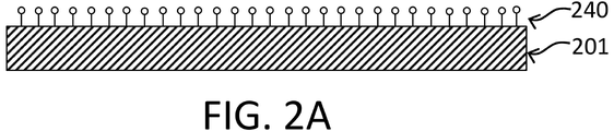
- a diazonium multilayer film is formed as a protective film 240 on the surface of the electrode 201 .
- the protective membrane 240 prevents HSA, IgG, and other biomolecular contaminants from approaching the electrode 201 while allowing the biomolecule of interest, glycoalbumin, to access the electrode 201 .
- the protective film 240 shown in FIG. 2A may be a diazonium multilayer film.
- the sensor may include an electrode, a protective film placed on the electrode, and an aptamer placed in a position that can bind to the biomolecule of interest.
- FIG. 2B shows sensor 200 as one embodiment.
- Sensor 200 includes electrode 201 , protective film 240 covering the surface of electrode 201 , and aptamer 202 immobilized on the surface of protective film 240 .
- Protective film 240 also functions as an anchor for fixing aptamer 202 on electrode 201 .
- the protective film 240 can also be called an anchor layer.
- An aptamer 202 can be formed at one end of the anchor layer 240 of FIG. 2A (FIG. 2B). This aptamer 202 may be similar to aptamer 102 of FIGS. 1A-1C.
- Aptamers 202 bind to target biomolecules 220 and do not bind to contaminants 230 .
- the protective film (anchor layer) 240 can further prevent noise-causing substances such as contaminants from reacting with the electrode 201 . Thereby, the measurement accuracy can be improved.
- the protective film may have fouling resistance (fouling suppression ability).
- the overcoat may include polyethylene glycol (PEG). Generally, PEG has fouling resistance.
- PEG may be grown or placed directly on the electrode.
- PEG (second overcoat) may be attached to an anchor layer (first overcoat) formed over the electrode.
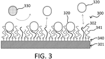
- a first protective film (anchor layer) 340 is formed on an electrode 301, and an aptamer 302 and a second protective film (PEG, anti-fouling layer) 341 are formed thereon. It is PEG is not present at the surface sites of anchor layer 340 where aptamers 302 are present. Thus, the biomolecule of interest 320 can bind to the aptamer 302 .
- PEG may be, for example and without limitation, PEG (eg, may have a molecular weight of 800, 2000, etc.).
- the first protective film (anchor layer) 340 shown in FIG. 3 may be the same anchor layer 240 as in FIGS. 2A and 2B.
- the anti-fouling layer 341 can further prevent noise-causing substances caused by contaminants 330 from reacting with the electrode 301 . Thereby, the measurement accuracy can be further improved.
- FIG. 4A shows the measurement results of a sensor with no aptamer and only the anchor layer placed on the electrode.
- the vertical axis indicates the imaginary axis (Z'') and the horizontal axis indicates the real axis (Z').
- the charge transfer resistance Rct is obtained from the diameter of the semicircle of the Nyquist plot.
- this R value was too large due to the installation, possibly due to the anchor layer, making it difficult to represent a semicircle. Since the anchor layer is considered to be an insulating film in a sense, evaluation was performed using the C component.
- the vertical axis represents the imaginary axis (C'') of capacitance
- the horizontal axis represents the real axis (C') of capacitance.
- ⁇ is the angular frequency
- a similar representation is adopted for other Nyquist plots.
- the impedance measurement may comprise scanning frequencies.
- the concentration may be obtained from a characteristic such as the diameter D of the semicircle of the Nyquist plot.
- the concentration may be obtained based on the displacement (D ⁇ D 0 ) from the diameter D 0 when the target biomolecule concentration is zero.
- the density may be obtained based on the ratio of the displacement (D ⁇ D 0 ) to the diameter D 0 of zero density, (D ⁇ D 0 )/D 0 .
- a calibration curve between the concentration and the characteristics of the Nyquist plot may be prepared in advance.
- impedance measurements may be made at multiple frequencies or at a single frequency. For example, a relationship between a predetermined frequency and concentration may be determined in advance to create a calibration curve. In actual measurements, concentrations may be determined based on measurements at one or more predetermined frequencies.
- glycoalbumin (GA) was introduced into the above sensor and EIS measurement was performed.
- the output of this electrode varied with changes in the concentration of GA. That is, in this sensor, the anchor layer is densely formed, but Ru complex ions, which are mediators, can permeate the anchor layer.
- GA non-specifically adsorbs to the surface of the anchor layer and prevents mediators from entering the electrode surface. That is, the capacitance decreases as the GA concentration increases. From the viewpoint of comparison with the following, the signal was measured in a situation where no aptamer was placed.
- FIG. 4B shows the measurement results of a sensor with a PEG layer.
- An anchor layer similar to that in FIG. 4A was formed on another electrode from the sensor in FIG. 4A, and a PEG layer was formed thereon. Therefore, the anchor layer may be considered substantially identical between FIGS. 4A and 4B.
- no aptamer is formed. Tears (with tears) and a PBS solution (w/o tears) were introduced to the electrodes, respectively, and EIS measurements were performed. Tears contain proteins such as albumin and glycoalbumin. The PBS solution did not contain those proteins. As shown in FIG. 4B, no difference was found between tears and PBS in electrode output.
- FIG. 5 shows the relationship between the concentration of GA in solution (horizontal axis) and (DD 0 )/D 0 (vertical axis) based on the measurement results shown in FIGS. 4A and 4B. It can be seen that the value of (D ⁇ D 0 )/D 0 changes especially at 1 mg/mL with the anchor layer alone, and does not change nearly at any concentration with the PEG layer. it is obvious. This result therefore means that contaminants such as proteins in tears were blocked or repelled by the PEG layer and did not reach the electrodes. Thus, it was confirmed that the anti-fouling layer (PEG in this example) has a high ability to block protein contaminants.
- the protective membrane may comprise bovine serum albumin (BSA).
- BSA bovine serum albumin
- BSA has fouling resistance.
- BSA may be grown or deposited directly on the electrode.
- BSA (second overcoat) may be attached to an anchor layer (first overcoat) formed over the electrode.
- the BSA may or may not be anchored to the anchor layer.
- a BSA molecule may be placed between the aptamers 402 .
- the biomolecule of interest 420 can bind to the aptamer 402 .
- a sensor 400 shown in FIG. 6 has a first protective film (anchor layer) 440 formed on an electrode 401, and an aptamer 402 and a second protective film (BSA, anti-fouling layer) 441 formed thereon. It is
- the first protective film (anchor layer) 440 shown in FIG. 6 may be the same anchor layer 240 as in FIGS. 2A and 2B.
- the BSA layer 441 can further prevent noise-causing substances such as contaminants 430 from reacting with the electrode 401 . Thereby, the measurement accuracy can be further improved.
- the protective membrane may have a molecular template (MIP).
- MIP molecular template
- the MIP may be grown or placed directly on the electrode.
- the MIP may be attached to an anchor layer (first overcoat) formed over the electrode.
- a sensor 500 shown in FIG. 7 has a first protective film (anchor layer) 540 formed on an electrode 501, and a MIP layer 541 formed thereon.
- the first protective film (anchor layer) 540 shown in FIG. 7 may be the same anchor layer 240 as in FIGS. 2A and 2B.
- the MIP layer 541 may be formed by, for example and without limitation, polymerizing a monomer of 2-(methacryloyloxy)ethyl 2-(trimethylammonio)ethylphosphate. This may form a layer of 2-methacryloyloxyethylphosphorylcholine (MPC) polymer.
- MPC 2-methacryloyloxyethylphosphorylcholine
- the aptamer 542 protrudes at one end inside the molecular template site (MIP) 542 of the MIP layer 541 .
- the MCP polymer forming MIP layer 541 may be provided with functional groups that recognize the biomolecules of interest at the exposed end of MIP 542, as shown in FIG. This functional group may be phenylboronic acid (PBA).
- the sensor 500 shown in FIG. 7 suppresses non-specific adsorption of contaminants by the MIP 542 and the MIP layer 541, and recognizes the target biomolecule 520 more specifically by the MIP 542, the aptamer 502 therein, and the PBA 543, It is possible to prevent other noise source substances such as impurities 530 from reacting with the electrode 501 . Thereby, the measurement accuracy can be further improved.
- Example 1 GA sensor> Using the sensor having the structure shown in FIG. 3, electrode outputs were examined for multiple proteins.
- the sensor used consisted of an electrode, an anchor layer (first protective layer) formed of a diazonium multilayer film placed thereon, an aptamer for GA and a PEG layer (resistant layer) on the anchor layer. fouling layer, second protective layer).
- a GA sensor was used.
- the sensor has an Au electrode as an electrode, a diazonium multilayer film as a first protective film, a PEG layer as a second protective layer (anti-fouling layer), and the sequence of SEQ ID NO: 1 (Table 1) as an aptamer. Specific binding Nucleic Acid Ligands were used.
- the measurement procedure is as follows. 1) First, phosphate-buffered saline (PBS) solutions of proteins GA, HSA, and IgG were prepared at the following concentrations. GA: 0, 0.01, 0.1, 1 mg/mL HSA: 0, 0.01, 0.1, 1 mg/mL IgG: 0, 0.01, 0.1, 1 mg/mL
- concentrations of GA, HSA, and IgG mean that PBS solutions containing no protein were used.
- Each protein at each concentration described above was introduced into the sensor. At this stage, GA binds to the aptamer and no other proteins.
- B/F (Bond/Free) separation was performed.
- washing may be performed using SDS (sodium dodecyl sulfate).
- SDS sodium dodecyl sulfate
- substances that have not bound to the aptamer or that have non-specifically adsorbed to the sensor surface, eg, the surface of the PEG layer are washed away from the sensor.
- proteins other than GA, that is, contaminants, and GA that did not bind to the aptamer do not contribute to the intended measurement and may cause noise. These noise sources can be removed.
- a ruthenium complex [Ru(NH 3 ) 6 ] 2+ ) was then introduced and EIS was used to analyze the dependence of the electrode output on protein concentration.
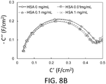
- FIG. 8A to 8C show multiple concentration Nyquist plots for each protein. As shown in FIG. 8A, it was observed that the plot varied significantly with concentration for GA. On the other hand, as shown in FIG. 8B, with HSA, the plot changed slightly, but did not change significantly. With IgG, the plots were almost unchanged, as shown in FIG. 8C.
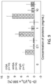
- Figure 9 shows the difference between the concentration of each protein (horizontal axis) and the diameter displacement (D-D 0 )/D 0 (vertical axis) of the Nyquist plot based on the measurement results shown in Figures 8A to 8C. Show relationship.
- the value of (D ⁇ D 0 )/D 0 is concentration dependent in GA and virtually concentration independent or much less concentration dependent in HSA and IgG than in GA. It became clear. Therefore, such a configuration can be used to manufacture a sensor that specifically recognizes GA or measures the concentration of GA.
- the present disclosure also provides an albumin sensor.
- the albumin sensor comprises an electrode and an albumin antibody (HSA antibody, anti-albumin antibody) placed on or near the electrode.
- HSA antibody albumin antibody
- anti-albumin antibody placed on or near the electrode.
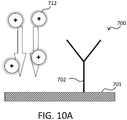
- FIG. 10A shows an albumin sensor 700 according to one embodiment.
- Albumin sensor 700 comprises electrode 701 and albumin antibody (HSA antibody) 702 disposed on electrode 701 .
- Albumin sensor 700 can detect or measure introduced mediator 712 with electrode 701 .
- albumin 720 When the target biomolecule, albumin 720, is introduced, albumin 720 is recognized and captured by albumin antibody 720 (Fig. 10B). Trapped albumin 720 reduces the effective surface area of electrode 701 and limits the access of mediator 712 to electrode 701 . In other words, in the situation of FIG. 10B, the resistance (R) is large and the capacitance (C) is small, relative to the situation of FIG. 10A.
- FIG. 11A shows a sensor 800 according to one embodiment.
- the sensor 800 comprises an electrode 801 , a protective film 840 covering the surface of the electrode 801 , and an antibody 802 immobilized on the surface of the protective film 840 .
- Protective film 840 may be, for example, without limitation, similar to anchor layer 240 shown in FIG. 2B.
- An antibody 802 may be formed at one end of a protective film (anchor layer) 840, similar to FIG. 2B.
- Antibody 802 binds to albumin 820 , which is the biomolecule of interest, and does not bind to contaminants 830 .
- the protective layer 840 can further prevent noise-causing substances such as contaminants from reacting with the electrode 801 . Thereby, the measurement accuracy can be improved.
- FIG. 11B shows a sensor 900 according to one embodiment.
- a sensor 900 has a first protective film (anchor layer) 940 formed on an electrode 901, and an antibody 902 and a second protective film (PEG, anti-fouling layer) 941 formed thereon.
- PEG is not present at the surface sites of anchor layer 340 where antibody 902 is present.
- biomolecules of interest 920 can bind to antibodies 902 .
- PEG may be, for example and without limitation, PEG-800 and PEG-2000.
- the first protective film (anchor layer) 940 shown in FIG. 11B may be the same anchor layer 240 as in FIGS. 2A and 2B.
- the anti-fouling layer 941 can further prevent noise-causing substances caused by contaminants 930 from reacting with the electrode 901 . Thereby, the measurement accuracy can be further improved.
- HSA sensor> Using the sensor having the structure shown in FIG. 11B, the output of the electrodes was investigated for GA and HSA.
- the sensor used consisted of an electrode, an anchor layer (first protective layer) formed of a diazonium multilayer film disposed thereon, and an anti-albumin antibody and a PEG layer (anti-fouling) on the anchor layer. layer, second protective layer).
- the measurement procedure is as follows. 1) First, phosphate-buffered saline (PBS) solutions of proteins HSA and GA were prepared at the following concentrations. HSA: 0, 0.1, 1, 10 mg/mL GA: 0, 0.1, 1, 10 mg/mL
- concentration of HSA and GA 0 mg/mL
- B/F Bond/Free separation was performed. For example, washing may be performed using SDS (sodium dodecyl sulfate).
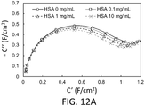
- Figures 12A and 12B show multiple concentration Nyquist plots for HSA and GA, respectively.
- HSA was observed to change the plot with concentration.
- FIG. 12B the plot changed in GA, but not as much as in FIG. 12A.
- the reason why the output from the HSA antibody is thus affected by GA is considered to be the non-specific adsorption of GA to the HSA antibody.
- the possibility that the HSA antibody used in this example also recognizes GA will be examined.
- Figure 13 shows the difference between the concentration of each protein (horizontal axis) and the diameter displacement (D-D 0 )/D 0 (vertical axis) of the Nyquist plot based on the measurement results shown in Figures 12A and 12B. Show relationship. The value of (D ⁇ D 0 )/D 0 was found to be concentration dependent in HSA. Such a configuration can therefore be used to fabricate a sensor for measuring the concentration of albumin in solution.
- the effects of GA seen in FIGS. 12B and 13 can be removed or corrected.
- an antibody that specifically recognizes HSA (or non-glycated albumin) but does not recognize GA may be used.
- the GA value is the sum (denominator) of the non-glycated albumin concentration ([HSA]) determined using the HSA antibody and the glycated albumin concentration ([GA]) determined using the GA aptamer. It can be obtained as a ratio ([GA]/ ⁇ [HSA]+[GA] ⁇ ) of the concentration (molecule) ([GA]) of glycated albumin.
- the output of the sensor with the HSA antibody is the sum of the concentration of non-glycated albumin and part of the concentration of glycated albumin ([HSA]+ ⁇ [GA]). . Therefore, by specifying the ratio ⁇ , the original HSA concentration can be obtained. It is conceivable that specific or non-specific effects by other substances, such as IgG, can be similarly or otherwise removed or corrected.
- a calibration curve can be generated based on the data shown in FIG. Using this calibration curve, GA concentration and albumin concentration are determined. GA values can be determined as the ratio of GA concentration to albumin concentration.
- the method of obtaining the GA value is not limited to the above.
- the GA value is obtained by dividing the amount of glycated albumin by the total amount of non-glycated and glycated albumin.
- the GA value may be determined based on the concentration of non-glycated albumin (HSA) and the concentration of GA determined by other sensors.
- a value calculated using the total value of non-glycated albumin (HSA) concentration and glycated albumin (GA) concentration or both, and the concentration of GA determined by another sensor Based on this, the GA value may be obtained.
- a device for measuring GA values may comprise a GA sensor and an albumin sensor.
- the GA sensor and albumin sensor may be configured to receive and measure the same solution to be measured.
- both sensors may be placed inside the container, channel, or volume of the solution to be measured.
- the device may be configured such that the GA sensor and the albumin sensor are arranged inside different containers, and the solution to be measured is divided and introduced into each container.
- the albumin sensor is a sensor that measures the total amount of glycated and non-glycated albumin or the amount of non-glycated albumin.
- the form of the albumin sensor used in the dual sensor of the present disclosure should not be particularly limited.
- a device for measuring GA values may include a GA sensor and an albumin sensor.
- a system or unit for measuring GA values may be configured to interface with a GA sensor and an albumin sensor.
- EIS was performed as follows. Using a BAS electrochemical analyzer, the frequency was scanned from 100 to 1,000,000 Hz (1 MHz) and impedance measurements were made at each frequency. The initial voltage was -0.14V. A phosphate buffer solution (pH 7.4) containing Ru complex ions was used as a mediator. A phosphate buffer solution (pH 7.4) was used to measure the reaction between a protein such as GA and the electrode without adding Ru complex ions. After the reaction of protein and aptamer, it was washed, ie B/F separation, and measured.
- FIG. 14 shows the process of a method for measuring biomolecules, according to an embodiment.
- a device or apparatus is provided or prepared that includes an electrode and an aptamer that specifically binds to a target biomolecule in the vicinity thereof.
- a cationic mediator is introduced into the system. Cationic mediators bind to oppositely charged aptamers.
- a target biomolecule is introduced. A solution containing or potentially containing the biomolecule of interest may be introduced into the system.
- an electrical signal is read at the electrode resulting from the reaction (eg, redox reaction) between the cation mediator and the electrode. This identifies the amount of the target biomolecule bound to the aptamer, such as the concentration of the target biomolecule in the introduced solution.
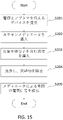
- FIG. 15 illustrates the process of a biomolecule measurement method, according to an embodiment.
- Steps S201 to S203 are the same, or at least the same in purpose, as steps S101 to S103.
- step S204 contaminants present in the system may be removed. This step may be called washing. This step may include B/F separation.
- step S205 an electrical signal is read at the electrode resulting from the reaction (eg, redox reaction) between the cation mediator and the electrode. This identifies the amount of the target biomolecule bound to the aptamer, such as the concentration of the target biomolecule in the introduced solution.
- Cleaning in step S204 removes or reduces contaminants that may affect measurement, thereby enabling more accurate measurement.
- a method of detecting a biomolecule comprising: providing an electrode and an aptamer that specifically binds to a biomolecule of interest located in the vicinity of the electrode or immobilized on the electrode; introducing a cationic mediator to the electrode on which the aptamer is disposed; contacting the aptamer with a solution containing the biomolecule of interest to allow the aptamer to bind to the biomolecule; and measuring an electrical signal generated at the electrode due to the cationic mediator; How to prepare.
- A001b The method of embodiment A001 or any embodiment, wherein wherein said mediator is a cationic mediator; Method.
- a method of detecting a biomolecule comprising: providing an electrode and a charged aptamer that specifically binds to a biomolecule of interest and is located near or immobilized on the electrode; introducing a mediator having a charge opposite to the charge of the aptamer to the electrode on which the aptamer is disposed; contacting the aptamer with a solution containing the biomolecule of interest to allow the aptamer to bind to the biomolecule; and measuring an electrical signal generated at the electrode due to the mediator; How to prepare.
- A002 The method of any one of embodiments A001 through A001c or any embodiment, wherein The method further comprising determining the amount of the biomolecule of interest in the solution based on the electrical signal.
- A002b The method of embodiment A002 or any embodiment, wherein: determining the amount of the biomolecule of interest in solution based on the capacitance component of the electrical signal; Method.
- A002c The method of embodiment A002 or any embodiment, wherein: determining the amount of the biomolecule of interest in the solution based on the current component of the electrical signal; Method.
- A003 The method of any one of embodiments A001 through A002c or any embodiment, wherein measuring the electrical signal generated at the electrode due to the mediator comprises performing electrochemical impedance spectroscopy; Method.
- A004 The method of embodiment A003 or any embodiment, wherein: evaluating the capacitance component of the mediator redox reaction at the electrode obtained by the electrochemical impedance spectroscopy; Method.
- A004b The method of embodiment A003 or any embodiment, wherein: evaluating a value for the charge transfer resistance (Rct) of the mediator redox reaction at the electrode obtained by the electrochemical impedance spectroscopy; Method.
- A005 The method of embodiment A004 or any embodiment, wherein: determining the amount of the biomolecule of interest bound to the aptamer based on the value of the capacitance component of the mediator redox reaction at the electrode; Method.
- A005b The method of embodiment A004 or any embodiment, wherein: determining the amount of the biomolecule of interest bound to the aptamer based on the value for the charge transfer resistance (Rct) of the mediator redox reaction at the electrode; Method.
- A011 The method of any one of embodiments A001 through A005b or any embodiment, wherein wherein the biomolecule of interest is a glycated protein; Method.
- A012 The method of embodiment A011 or any embodiment, wherein The biomolecule of interest is glycoalbumin, Method.
- A013 The method of any one of embodiments A001 through A005b or any embodiment, wherein The biomolecule of interest is one or more selected from the group consisting of cells, viruses, and extracellular vesicles. Method.
- A021 The method of embodiment A012 or any embodiment, wherein The aptamer comprises the base sequence of SEQ ID NO: 1, Method.
- A031 The method of any one of embodiments A001 through A021 or any embodiment, wherein the mediator is a ruthenium complex, Method.
- A041 The method of any one of embodiments A001 through A031 or any embodiment, wherein introducing the mediator to the electrode on which the aptamer is arranged is performed before contacting the biomolecule with the aptamer; Method.
- A042 The method of embodiment A041 or any embodiment, wherein after introducing the mediator to the electrode on which the aptamer is disposed, and before contacting the biomolecule with the aptamer, The method further comprising substantially removing mediators that did not bind to the aptamer.
- A051 The method of any one of embodiments A001 through A042 or any embodiment, wherein measuring an electrical signal generated at the electrode due to the mediator comprises performing an impedance measurement; Method.
- B001 A method for evaluating the degree of saccharification of a protein, comprising: providing an electrode having disposed thereon an aptamer that specifically binds to a glycated protein of interest; introducing a solution containing a glycated protein of interest and a non-glycated protein of interest to the electrode to allow the protein of interest to bind to the aptamer; introducing a mediator to the electrode on which the aptamer is disposed; measuring an electrical signal generated at the electrode due to the mediator; Determining the amount of the protein to be glycated in the solution based on the measured electrical signal; Determining the amount of protein to be glycated, or the total amount of said protein to be glycated and non-glycated, in said solution; determining the degree of saccharification of
- a method for evaluating the degree of saccharification of a protein comprising: Providing a first electrode on the surface of which an aptamer that specifically binds to a target protein for glycation is arranged; providing a second electrode having disposed thereon an antibody that recognizes the protein of interest; Introducing a solution containing the protein to be glycated and the protein of interest to the first electrode and the second electrode, binding the protein to be glycated to the aptamer, and binding the protein of interest to the antibody; introducing a mediator to the first electrode and the second electrode on which the aptamer is disposed; measuring a first electrical signal generated at the first electrode and a second electrical signal generated at the second electrode due to the mediator; and measuring the measured first electrical signal and the second electrical signal.
- a device for detecting biomolecules comprising: an electrode; and an aptamer disposed on the surface of the electrode and specifically binding to a biomolecule of interest; with contacting the aptamer with a solution containing the target biomolecule; introducing a mediator to the electrode on which the aptamer is disposed; measuring an electrical signal generated at the electrode due to the mediator;
- a device configured to C002 The apparatus of embodiment C001 or any embodiment, wherein: wherein said mediator is a cationic mediator; Device.
- C011 The apparatus of embodiment C001 or any embodiment, wherein: a protective film disposed on the surface of the electrode, the protective film having the ability to allow the mediator to pass toward the electrode and to inhibit contaminants from passing toward the electrode; Further equipment.
- C012 The apparatus of embodiment C011 or any embodiment, wherein: The protective film has a diazonium multilayer film, Device.
- C013 The apparatus of embodiment C012 or any embodiment, wherein: the aptamer is anchored to the diazonium multilayer; Device.
- C014 The apparatus of any one of embodiments C011 through C013 or any embodiment, wherein:
- the protective film comprises a second protective film having anti-fouling performance, Device.
- the protective film comprises a second protective film having anti-fouling performance formed on the surface of the diazonium multilayer film, Device.
- C016 The apparatus of embodiment C014 or C015 or any embodiment, wherein: wherein the second protective film consists essentially of polyethylene glycol (PEG) or bovine serum albumin (BSA); Device.
- PEG polyethylene glycol
- BSA bovine serum albumin
- C021 The apparatus of any one of embodiments C011 through C013 or any embodiment, wherein:
- the protective film has a molecular template (MIP) that recognizes the target biomolecule and has one end of the aptamer inside it. Device.
- MIP molecular template
- C022 The apparatus of embodiment C021 or any embodiment, wherein: The apparatus, wherein the molecular template has a functional group that recognizes the target biomolecule on its inner surface.
- C023 The apparatus of embodiment C021 or any embodiment, wherein: the functional group is phenylboronic acid (PBA); Device.
- PBA phenylboronic acid
- C031 The apparatus of any one of embodiments C001 through C023 or any embodiment, wherein: The apparatus further comprising a measuring device connected to said electrodes.
- C032 The apparatus of any one of embodiments C011 through C023 or any embodiment, wherein: The measuring device is capable of performing measurements using electrochemical impedance spectroscopy. device.
- C101 A device for measuring glycoalbumin, comprising: an electrode; and an aptamer disposed on the surface of said electrode and having the sequence of SEQ ID NO: 1; device with D001 A device for obtaining a GA value, a device for measuring glycoalbumin according to embodiment C101 or any embodiment; and a device for measuring albumin, Device.
- D002 The apparatus of embodiment D001 or any embodiment, wherein: The device for measuring albumin comprises an electrode; and an anti-albumin antibody disposed on the surface of the electrode. Device.
Landscapes
- Health & Medical Sciences (AREA)
- Life Sciences & Earth Sciences (AREA)
- Immunology (AREA)
- Chemical & Material Sciences (AREA)
- Engineering & Computer Science (AREA)
- Molecular Biology (AREA)
- Physics & Mathematics (AREA)
- Biomedical Technology (AREA)
- Pathology (AREA)
- Hematology (AREA)
- General Physics & Mathematics (AREA)
- Urology & Nephrology (AREA)
- Biochemistry (AREA)
- Analytical Chemistry (AREA)
- General Health & Medical Sciences (AREA)
- Food Science & Technology (AREA)
- Medicinal Chemistry (AREA)
- Chemical Kinetics & Catalysis (AREA)
- Biotechnology (AREA)
- Microbiology (AREA)
- Cell Biology (AREA)
- Electrochemistry (AREA)
- Spectroscopy & Molecular Physics (AREA)
- Tropical Medicine & Parasitology (AREA)
- Biophysics (AREA)
- Investigating Or Analyzing Materials By The Use Of Electric Means (AREA)
Priority Applications (4)
| Application Number | Priority Date | Filing Date | Title |
|---|---|---|---|
| JP2023536704A JPWO2023002892A1 (https=) | 2021-07-18 | 2022-07-13 | |
| EP22845826.1A EP4375654A4 (en) | 2021-07-18 | 2022-07-13 | METHOD AND DEVICE FOR DETECTING BIOMOLECULES |
| US18/579,722 US20240310372A1 (en) | 2021-07-18 | 2022-07-13 | Method and device for detecting biomolecule |
| CN202280046798.6A CN117677839A (zh) | 2021-07-18 | 2022-07-13 | 检测生物分子的方法和装置 |
Applications Claiming Priority (2)
| Application Number | Priority Date | Filing Date | Title |
|---|---|---|---|
| JP2021-118354 | 2021-07-18 | ||
| JP2021118354 | 2021-07-18 |
Publications (1)
| Publication Number | Publication Date |
|---|---|
| WO2023002892A1 true WO2023002892A1 (ja) | 2023-01-26 |
Family
ID=84979166
Family Applications (1)
| Application Number | Title | Priority Date | Filing Date |
|---|---|---|---|
| PCT/JP2022/027516 Ceased WO2023002892A1 (ja) | 2021-07-18 | 2022-07-13 | 生体分子を検出する方法及び装置 |
Country Status (5)
| Country | Link |
|---|---|
| US (1) | US20240310372A1 (https=) |
| EP (1) | EP4375654A4 (https=) |
| JP (1) | JPWO2023002892A1 (https=) |
| CN (1) | CN117677839A (https=) |
| WO (1) | WO2023002892A1 (https=) |
Cited By (1)
| Publication number | Priority date | Publication date | Assignee | Title |
|---|---|---|---|---|
| WO2025121412A1 (ja) * | 2023-12-08 | 2025-06-12 | 株式会社エヌエフホールディングス | 第2メディエータの選択方法、検出方法および検出システム |
Families Citing this family (1)
| Publication number | Priority date | Publication date | Assignee | Title |
|---|---|---|---|---|
| CN120761464B (zh) * | 2025-09-09 | 2025-11-21 | 浙江大学 | 一种电化学多靶标联合检测电极及其制备方法 |
Citations (5)
| Publication number | Priority date | Publication date | Assignee | Title |
|---|---|---|---|---|
| US20140170766A1 (en) * | 2007-08-06 | 2014-06-19 | Epinex Diagnostics, Inc. | Aptamer Based Point-of-Care Test for Glycated Albumin |
| WO2015057177A2 (en) * | 2013-10-17 | 2015-04-23 | National Science And Technology Development Agency | Aptamers bound human serum albumin and glycated human serum albumin |
| JP2015087293A (ja) * | 2013-10-31 | 2015-05-07 | 日立化成株式会社 | グリコアルブミンの測定キットおよび測定方法 |
| WO2019188902A1 (ja) * | 2018-03-30 | 2019-10-03 | 株式会社Provigate | バイオセンサ |
| WO2022067051A1 (en) * | 2020-09-24 | 2022-03-31 | University Of Cincinnati | Aptamer sensors with reference and counter voltage control |
-
2022
- 2022-07-13 JP JP2023536704A patent/JPWO2023002892A1/ja active Pending
- 2022-07-13 EP EP22845826.1A patent/EP4375654A4/en active Pending
- 2022-07-13 US US18/579,722 patent/US20240310372A1/en active Pending
- 2022-07-13 CN CN202280046798.6A patent/CN117677839A/zh active Pending
- 2022-07-13 WO PCT/JP2022/027516 patent/WO2023002892A1/ja not_active Ceased
Patent Citations (5)
| Publication number | Priority date | Publication date | Assignee | Title |
|---|---|---|---|---|
| US20140170766A1 (en) * | 2007-08-06 | 2014-06-19 | Epinex Diagnostics, Inc. | Aptamer Based Point-of-Care Test for Glycated Albumin |
| WO2015057177A2 (en) * | 2013-10-17 | 2015-04-23 | National Science And Technology Development Agency | Aptamers bound human serum albumin and glycated human serum albumin |
| JP2015087293A (ja) * | 2013-10-31 | 2015-05-07 | 日立化成株式会社 | グリコアルブミンの測定キットおよび測定方法 |
| WO2019188902A1 (ja) * | 2018-03-30 | 2019-10-03 | 株式会社Provigate | バイオセンサ |
| WO2022067051A1 (en) * | 2020-09-24 | 2022-03-31 | University Of Cincinnati | Aptamer sensors with reference and counter voltage control |
Non-Patent Citations (2)
| Title |
|---|
| MIYASAKA SUMITO, TOSHIYA SAKATA: "Selective detection of low-molecular-weight stress marker using aptamer-based transistor", JSAP ANNUAL MEETINGS EXTENDED ABSTRACTS, 1 January 2018 (2018-01-01), XP093026503, Retrieved from the Internet <URL:https://confit.atlas.jp/guide/event-img/jsap2018a/19p-221C-7/public/pdf?type=in> [retrieved on 20230223] * |
| See also references of EP4375654A4 * |
Cited By (1)
| Publication number | Priority date | Publication date | Assignee | Title |
|---|---|---|---|---|
| WO2025121412A1 (ja) * | 2023-12-08 | 2025-06-12 | 株式会社エヌエフホールディングス | 第2メディエータの選択方法、検出方法および検出システム |
Also Published As
| Publication number | Publication date |
|---|---|
| EP4375654A1 (en) | 2024-05-29 |
| US20240310372A1 (en) | 2024-09-19 |
| JPWO2023002892A1 (https=) | 2023-01-26 |
| CN117677839A (zh) | 2024-03-08 |
| EP4375654A4 (en) | 2025-07-16 |
Similar Documents
| Publication | Publication Date | Title |
|---|---|---|
| KR102138106B1 (ko) | 피분석물을 검출 및 측정하기 위한 방법 및 장치 | |
| Wang et al. | Antifouling and ultrasensitive biosensing interface based on self-assembled peptide and aptamer on macroporous gold for electrochemical detection of immunoglobulin E in serum | |
| EP3586115B1 (en) | Analyte detector for detecting at least one analyte in at least one fluid sample | |
| JP6280632B2 (ja) | 透明なマイクロアレイで正確にpHをモニターするためのデバイスおよび方法 | |
| Ferreira et al. | An ultrasensitive Cystatin C renal failure immunosensor based on a PPy/CNT electrochemical capacitor grafted on interdigitated electrode | |
| US10330677B2 (en) | Electrochemical aptasensors with a gelatin B matrix | |
| WO2023002892A1 (ja) | 生体分子を検出する方法及び装置 | |
| Bertok et al. | Comparison of the 2D and 3D nanostructured lectin-based biosensors for in situ detection of sialic acid on glycoproteins | |
| CN107438763A (zh) | 量子电容感测 | |
| Alizadeh et al. | Synthesis and application of different nano-sized imprinted polymers for the preparation of promethazine membrane electrodes and comparison of their efficiencies | |
| US20150355133A1 (en) | Nano-well based electrical immunoassays | |
| Zakaria et al. | An impedimetric micro-immunosensing assay to detect Alzheimer's disease biomarker: Aβ40 | |
| Ahlawat et al. | Gold-coated nanoporous polycarbonate track–etched solid platform for the rapid detection of mesothelin | |
| JPWO2023002892A5 (https=) | ||
| Saputra et al. | Dual-signal output biosensor for the detection of program death-ligand 1 and therapy progress monitoring of cancer | |
| Hartati et al. | A voltammetric epithelial sodium channels immunosensor using screen-printed carbon electrode modified with reduced graphene oxide | |
| WO2013164613A1 (en) | Electrochemical detection method | |
| Blel et al. | Ultrasensitive electrochemical sensors for psa detection: related surface functionalization strategies | |
| Niu et al. | A peptide-based antifouling aptasensor for tetracycline analysis | |
| KR102923506B1 (ko) | 검출용 센서 | |
| Zhang et al. | High-performance antifouling electrochemical aptsensor based on a Y-shaped glycopeptide and platinum nanoparticles for detecting aflatoxin B1 in food | |
| Kundacina et al. | A versatile gold leaf immunosensor with a novel functionalization strategy based on Protein L and Trastuzumab-modified surface for efficient HER2 detection | |
| WO2025047629A1 (ja) | 生体分子を測定する方法及び装置 | |
| Galyamin | Treball Final de Grau |
Legal Events
| Date | Code | Title | Description |
|---|---|---|---|
| 121 | Ep: the epo has been informed by wipo that ep was designated in this application |
Ref document number: 22845826 Country of ref document: EP Kind code of ref document: A1 |
|
| WWE | Wipo information: entry into national phase |
Ref document number: 202280046798.6 Country of ref document: CN |
|
| WWE | Wipo information: entry into national phase |
Ref document number: 2023536704 Country of ref document: JP |
|
| WWE | Wipo information: entry into national phase |
Ref document number: 202417007674 Country of ref document: IN |
|
| WWE | Wipo information: entry into national phase |
Ref document number: 2022845826 Country of ref document: EP |
|
| NENP | Non-entry into the national phase |
Ref country code: DE |
|
| ENP | Entry into the national phase |
Ref document number: 2022845826 Country of ref document: EP Effective date: 20240219 |