WO2023002653A1 - 空気調和機 - Google Patents
空気調和機 Download PDFInfo
- Publication number
- WO2023002653A1 WO2023002653A1 PCT/JP2022/005925 JP2022005925W WO2023002653A1 WO 2023002653 A1 WO2023002653 A1 WO 2023002653A1 JP 2022005925 W JP2022005925 W JP 2022005925W WO 2023002653 A1 WO2023002653 A1 WO 2023002653A1
- Authority
- WO
- WIPO (PCT)
- Prior art keywords
- air
- port
- damper
- outside
- return
- Prior art date
- Legal status (The legal status is an assumption and is not a legal conclusion. Google has not performed a legal analysis and makes no representation as to the accuracy of the status listed.)
- Ceased
Links
Images


Classifications
-
- F—MECHANICAL ENGINEERING; LIGHTING; HEATING; WEAPONS; BLASTING
- F24—HEATING; RANGES; VENTILATING
- F24F—AIR-CONDITIONING; AIR-HUMIDIFICATION; VENTILATION; USE OF AIR CURRENTS FOR SCREENING
- F24F1/00—Room units for air-conditioning, e.g. separate or self-contained units or units receiving primary air from a central station
- F24F1/0003—Room units for air-conditioning, e.g. separate or self-contained units or units receiving primary air from a central station characterised by a split arrangement, wherein parts of the air-conditioning system, e.g. evaporator and condenser, are in separately located units
-
- F—MECHANICAL ENGINEERING; LIGHTING; HEATING; WEAPONS; BLASTING
- F24—HEATING; RANGES; VENTILATING
- F24F—AIR-CONDITIONING; AIR-HUMIDIFICATION; VENTILATION; USE OF AIR CURRENTS FOR SCREENING
- F24F7/00—Ventilation
- F24F7/04—Ventilation with ducting systems, e.g. by double walls; with natural circulation
- F24F7/06—Ventilation with ducting systems, e.g. by double walls; with natural circulation with forced air circulation, e.g. by fan positioning of a ventilator in or against a conduit
- F24F7/08—Ventilation with ducting systems, e.g. by double walls; with natural circulation with forced air circulation, e.g. by fan positioning of a ventilator in or against a conduit with separate ducts for supplied and exhausted air with provisions for reversal of the input and output systems
-
- F—MECHANICAL ENGINEERING; LIGHTING; HEATING; WEAPONS; BLASTING
- F24—HEATING; RANGES; VENTILATING
- F24F—AIR-CONDITIONING; AIR-HUMIDIFICATION; VENTILATION; USE OF AIR CURRENTS FOR SCREENING
- F24F11/00—Control or safety arrangements
- F24F11/70—Control systems characterised by their outputs; Constructional details thereof
- F24F11/72—Control systems characterised by their outputs; Constructional details thereof for controlling the supply of treated air, e.g. its pressure
-
- F—MECHANICAL ENGINEERING; LIGHTING; HEATING; WEAPONS; BLASTING
- F24—HEATING; RANGES; VENTILATING
- F24F—AIR-CONDITIONING; AIR-HUMIDIFICATION; VENTILATION; USE OF AIR CURRENTS FOR SCREENING
- F24F13/00—Details common to, or for air-conditioning, air-humidification, ventilation or use of air currents for screening
- F24F13/08—Air-flow control members, e.g. louvres, grilles, flaps or guide plates
- F24F13/10—Air-flow control members, e.g. louvres, grilles, flaps or guide plates movable, e.g. dampers
-
- F—MECHANICAL ENGINEERING; LIGHTING; HEATING; WEAPONS; BLASTING
- F24—HEATING; RANGES; VENTILATING
- F24F—AIR-CONDITIONING; AIR-HUMIDIFICATION; VENTILATION; USE OF AIR CURRENTS FOR SCREENING
- F24F13/00—Details common to, or for air-conditioning, air-humidification, ventilation or use of air currents for screening
- F24F13/30—Arrangement or mounting of heat-exchangers
-
- F—MECHANICAL ENGINEERING; LIGHTING; HEATING; WEAPONS; BLASTING
- F24—HEATING; RANGES; VENTILATING
- F24F—AIR-CONDITIONING; AIR-HUMIDIFICATION; VENTILATION; USE OF AIR CURRENTS FOR SCREENING
- F24F3/00—Air-conditioning systems in which conditioned primary air is supplied from one or more central stations to distributing units in the rooms or spaces where it may receive secondary treatment; Apparatus specially designed for such systems
- F24F3/001—Air-conditioning systems in which conditioned primary air is supplied from one or more central stations to distributing units in the rooms or spaces where it may receive secondary treatment; Apparatus specially designed for such systems in which the air treatment in the central station takes place by means of a heat-pump or by means of a reversible cycle
-
- F—MECHANICAL ENGINEERING; LIGHTING; HEATING; WEAPONS; BLASTING
- F24—HEATING; RANGES; VENTILATING
- F24F—AIR-CONDITIONING; AIR-HUMIDIFICATION; VENTILATION; USE OF AIR CURRENTS FOR SCREENING
- F24F11/00—Control or safety arrangements
- F24F11/30—Control or safety arrangements for purposes related to the operation of the system, e.g. for safety or monitoring
- F24F11/32—Responding to malfunctions or emergencies
- F24F11/36—Responding to malfunctions or emergencies to leakage of heat-exchange fluid
-
- F—MECHANICAL ENGINEERING; LIGHTING; HEATING; WEAPONS; BLASTING
- F24—HEATING; RANGES; VENTILATING
- F24F—AIR-CONDITIONING; AIR-HUMIDIFICATION; VENTILATION; USE OF AIR CURRENTS FOR SCREENING
- F24F11/00—Control or safety arrangements
- F24F11/89—Arrangement or mounting of control or safety devices
-
- F—MECHANICAL ENGINEERING; LIGHTING; HEATING; WEAPONS; BLASTING
- F24—HEATING; RANGES; VENTILATING
- F24F—AIR-CONDITIONING; AIR-HUMIDIFICATION; VENTILATION; USE OF AIR CURRENTS FOR SCREENING
- F24F12/00—Use of energy recovery systems in air conditioning, ventilation or screening
- F24F12/001—Use of energy recovery systems in air conditioning, ventilation or screening with heat-exchange between supplied and exhausted air
- F24F12/006—Use of energy recovery systems in air conditioning, ventilation or screening with heat-exchange between supplied and exhausted air using an air-to-air heat exchanger
-
- F—MECHANICAL ENGINEERING; LIGHTING; HEATING; WEAPONS; BLASTING
- F24—HEATING; RANGES; VENTILATING
- F24F—AIR-CONDITIONING; AIR-HUMIDIFICATION; VENTILATION; USE OF AIR CURRENTS FOR SCREENING
- F24F13/00—Details common to, or for air-conditioning, air-humidification, ventilation or use of air currents for screening
- F24F13/02—Ducting arrangements
-
- F—MECHANICAL ENGINEERING; LIGHTING; HEATING; WEAPONS; BLASTING
- F24—HEATING; RANGES; VENTILATING
- F24F—AIR-CONDITIONING; AIR-HUMIDIFICATION; VENTILATION; USE OF AIR CURRENTS FOR SCREENING
- F24F2203/00—Devices or apparatus used for air treatment
- F24F2203/10—Rotary wheel
- F24F2203/104—Heat exchanger wheel
-
- Y—GENERAL TAGGING OF NEW TECHNOLOGICAL DEVELOPMENTS; GENERAL TAGGING OF CROSS-SECTIONAL TECHNOLOGIES SPANNING OVER SEVERAL SECTIONS OF THE IPC; TECHNICAL SUBJECTS COVERED BY FORMER USPC CROSS-REFERENCE ART COLLECTIONS [XRACs] AND DIGESTS
- Y02—TECHNOLOGIES OR APPLICATIONS FOR MITIGATION OR ADAPTATION AGAINST CLIMATE CHANGE
- Y02B—CLIMATE CHANGE MITIGATION TECHNOLOGIES RELATED TO BUILDINGS, e.g. HOUSING, HOUSE APPLIANCES OR RELATED END-USER APPLICATIONS
- Y02B30/00—Energy efficient heating, ventilation or air conditioning [HVAC]
- Y02B30/56—Heat recovery units
Definitions
- This disclosure relates to an air conditioner that supplies air to a room through a duct.
- a conventional air conditioner consists of a main duct installed on the ceiling or the like, an indoor unit installed in the middle of the main duct to divide the main duct into an intake side and an air outlet side, and a conditioned air generated by the indoor unit that is blown out.
- Patent Document 1 further includes an exhaust duct that communicates with the outside from the main duct on the blowout side, and an exhaust fan that is arranged in the exhaust duct.
- a leakage detection sensor is arranged in the main duct on the blowout side in preparation for leakage of the combustible refrigerant. Refrigerant was discharged outside from the main duct on the blowout side through the exhaust duct.
- Patent Document 1 when the air conditioner is stopped, that is, when the exhaust fan is stopped, the leaked refrigerant cannot be discharged to the outside, and the leaked refrigerant stays in the indoor unit. Since the outflow duct is always in communication with the room, in Patent Document 1, the leaked refrigerant that has accumulated in the indoor unit flows from the main duct on the suction side into the room via the outflow duct, possibly creating a flammable area in the room. There was a problem that there is
- the present disclosure has been made to solve such problems, and in an air conditioner that supplies air to a room through a duct, a flammable area is generated in the room even when the air conditioner is stopped.
- An object of the present invention is to obtain an air conditioner capable of suppressing this.
- An air conditioner according to the present disclosure is an air conditioner that operates a blower to supply conditioned air to a room through a supply air duct, and is connected to an outside air inlet for taking in outside air and an air supply duct to take in air from the outside air opening.
- a housing formed with an air supply port for supplying outside air into the room, a return air port for taking in air from the room, and an exhaust port for discharging the air taken in from the return air port to the outside; an outside-air-side air passage that communicates the outside-air port and the air supply port; an exhaust-side air passage that is formed separately from the outside-air-side air passage in the housing and communicates the return-air port and the exhaust port;
- An indoor heat exchanger arranged in an air passage through which a refrigerant flows, a blower arranged in an air passage on the outside air side and generating an air flow from an outside air port to the room through an air supply port and an air supply duct during operation, and an air supply.
- a damper that opens and closes a mouth is provided with an air supply damper that is opened when the blower is in operation and closed when the blower is stopped.
- the air supply damper is closed when the fan is stopped, so in a state where the air conditioner is stopped It is possible to suppress the generation of a combustible area in the room.
- FIG. 1 is a schematic diagram showing the overall configuration of an air conditioner according to Embodiment 1;
- FIG. FIG. 4 is a schematic diagram showing a modification of the air conditioner according to Embodiment 1;
- FIG. 2 is a schematic diagram showing the overall configuration of an air conditioner according to Embodiment 2;
- FIG. 11 is a schematic diagram showing the overall configuration of an air conditioner according to Embodiment 3;
- FIG. 11 is a schematic diagram showing a modification of the air conditioner according to Embodiment 3;
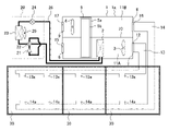
- FIG. 1 is a schematic diagram showing the overall configuration of an air conditioner according to Embodiment 1.
- FIG. 1 is a schematic diagram showing the overall configuration of an air conditioner according to Embodiment 1.
- the air conditioner has a fan unit 1 and an outdoor unit 20 installed outdoors.
- the fan unit 1 includes a blower 3 inside, and operates the blower 3 to supply conditioned air to the room 30 to be air-conditioned through an air supply duct 13 (hereinafter referred to as air supply). Since the air conditioner distributes conditioned air through the air supply duct 13 and supplies the air to the rooms 30 , one fan unit 1 can supply air to a plurality of rooms 30 .
- the conditioned air is the conditioned air temperature-controlled by the indoor heat exchanger 2 in the air-conditioning/ventilation operation described later, or the outside air taken in from the outside in the ventilation operation described later.
- the fan unit 1 has a rectangular parallelepiped housing 1a, and an indoor heat exchanger 2, a blower 3, a return fan 4, and a total heat exchanger 5 are arranged in the housing 1a.
- the housing 1a has an outside air port 6 that takes in air from the outside, an air supply port 7 that supplies the outside air taken in from the outside air port 6 to the room 30, a return air port 8 that takes in air from the room 30, and a return air port.
- An exhaust port 9 for discharging the air taken in from the air port 8 to the outside of the room is formed penetrating therethrough.
- a partition wall 10 is horizontally disposed inside the housing 1a, and the partition wall 10 vertically separates an outside air passage 11A and an exhaust air passage 11B inside the housing 1a.
- An outside-air-side air passage 11A is formed on the lower side of the housing 1a, and an exhaust-side air passage 11B is formed on the upper side of the housing.
- the air conditioner is not limited to the configuration in which the inside of the housing 1a is separated vertically, and may be configured to be separated horizontally.
- the outside air side air passage 11A is an air passage that connects the outside air port 6 and the air supply port 7, and is an air passage that supplies the outside air taken in from the outside air port 6 to the room 30 through the air supply port 7.
- the exhaust-side air passage 11B is an air passage that connects the return air port 8 and the exhaust port 9, and is an air passage that exhausts the air in the room 30 taken in from the return air port 8 to the outside from the exhaust port 9.
- the white arrows in FIG. 1 indicate the flow of air in the air passage 11A on the outside air side and the air passage 11B on the exhaust side.
- An indoor heat exchanger 2 and a blower 3 are arranged in order from the windward side of the outdoor air passage 11A.
- a return fan 4 is arranged in the exhaust-side air passage 11B.
- a total heat exchanger 5 is arranged in common in the middle of the air passage 11A on the outside air side and the air passage 11B on the exhaust side. The total heat exchanger 5 is arranged on the windward side of the indoor heat exchanger 2 in the outdoor air passage 11A and on the windward side of the return fan 4 in the exhaust air passage 11B.
- the blower 3 is driven during operation of the air conditioner, and generates an airflow from the outside air port 6 to the room 30 via the air supply port 7 and the air supply duct 13 described later.
- the return fan 4 is driven during operation of the air conditioner, and generates an airflow from the room 30 toward the exhaust port 9 via the return air duct 14 and the return air port 8 described later.
- the total heat exchanger 5 exchanges heat between outside air taken in from the outside air port 6 and air in the room 30 taken in from the return air port 8 .
- the total heat exchanger 5 is a device that recovers air-conditioning energy lost due to ventilation with the outside air by exchanging heat between the outside air passing through the outside air passage 11A and the exhaust air passing through the exhaust side air passage 11B.
- the total enthalpy heat exchanger 5 is a rotary type total enthalpy heat exchanger that has a configuration in which a honeycomb rotor 5b is arranged in a casing 5a that is separated into an outside air side and an exhaust side, and heat is exchanged by rotating the honeycomb rotor 5b. be.
- the total enthalpy heat exchanger 5 is not limited to a rotary type total enthalpy heat exchanger, and the flow path on the outside air side and the flow path on the exhaust side are separated by a flat sheet to form mutually independent flow paths. , a static total heat exchanger in which heat is exchanged between outside air and exhaust air.
- the fan unit 1 is connected with a supply air duct 13 for supplying the air after passing through the outside air passage 11A to each room 30, and a return air duct 14 for returning the air in each room 30 to the return air port 8. ing.
- the air supply duct 13 communicates the air supply port 7 with each room 30 .
- the air supply duct 13 extends from the air supply port 7 toward each room 30 , and blows air toward the room 30 from a blower outlet 13 a provided corresponding to each room 30 .
- the return air duct 14 extends from the return air port 8 toward each room 30, sucks the air in the room 30 from the suction port 14a provided corresponding to each room 30, and returns it to the return air port 8. .
- the air outlet 13a is located on the ceiling side of the room 30, and the suction port 14a is located on the floor side of the room. An air flow is formed.
- an air supply damper 12 that opens and closes the air supply port 7 is provided at the air supply port 7 .
- the supply air damper 12 is opened during operation of the air conditioner and closed while the operation of the air conditioner is stopped. Opening/closing control of the air supply damper 12 is performed by a control device (not shown).
- the fan unit 1 is not limited to the configuration in which the air supply damper 12 is provided in the air supply port 7, and may be configured to be provided in each blowout port 13a.
- the air supply damper 12 operates in the same manner as when it is provided at the air supply port 7 .
- the supply air damper 12 is opened while the air conditioner is in operation and closed while the air conditioner is stopped.
- the installation position of the fan unit 1 is not limited to outdoors. may be placed in
- the outdoor unit 20 includes a compressor 21 , a four-way valve 22 , an outdoor heat exchanger 23 , a pressure reducing device 24 and an outdoor fan 25 .
- the compressor 21 is a device that compresses refrigerant to increase the pressure and temperature of the refrigerant.
- a rotary compressor, a scroll compressor, or the like can be used as the compressor 21 .
- the decompression device 24 is a device that expands the refrigerant to reduce the pressure of the refrigerant.
- the decompression device 24 is composed of an electronic expansion valve (LEV) or the like.
- the air conditioner includes a compressor 21 installed in the outdoor unit 20, a four-way valve 22, an outdoor heat exchanger 23, a pressure reducing device 24, and an indoor heat exchanger 2 installed in the fan unit 1, which are connected to refrigerant pipes. 26 to form a refrigerant circuit in which the refrigerant circulates.
- the refrigerant piping 26 extending from the outdoor unit 20 to the outside of the outdoor unit 20 and the refrigerant piping 26 extending from the fan unit 1 to the outside of the fan unit 1 are connected to metal joints such as joints (not shown). are connected via and form a refrigerant circuit.
- An air conditioner selectively operates an air-conditioning/ventilation operation in which a refrigerant is circulated in a refrigerant circuit to perform air conditioning while performing a refrigeration cycle operation, and a ventilation operation in which only ventilation is performed without performing the refrigeration cycle operation. conduct.
- the air-conditioning/ventilation operation the compressor 21 and the outdoor fan 25 are operated, and the fan 3 is operated.
- the air conditioner can switch between the cooling operation and the heating operation by switching the four-way valve 22 to reverse the circulation direction of the refrigerant in the refrigerant circuit.
- the ventilation operation the compressor 21 and the outdoor fan 25 are stopped and the fan 3 is operated.
- air conditioners can be controlled by a remote controller in the room 30 or the like.
- "when the air conditioner is in operation” means that the air conditioner is performing the air conditioning/ventilation operation or the ventilation operation, and at least the blower 3 is operating.
- “when the air conditioner is stopped” means that the air conditioner has stopped the air conditioning ventilation operation or the ventilation operation, and unless otherwise specified, the compressor 21, the outdoor fan 25, the fan 3, and the return fan 4 are It indicates that it is stopped.
- GWP global warming potential
- the refrigerant used here is combustible and has a higher average molecular weight than air. That is, refrigerants are denser than air and heavier than air at atmospheric pressure. Therefore, the refrigerant has the property of sinking downward in the direction of gravity in the air.
- cooling operation In the air conditioner, during cooling operation, the refrigerant circulates in the order of the compressor 21, the outdoor heat exchanger 23, the decompression device 24, and the indoor heat exchanger 2, the indoor heat exchanger 2 functions as an evaporator, and the outdoor heat is Exchanger 23 functions as a condenser.
- the refrigerant circulates in the order of the compressor 21, the indoor heat exchanger 2, the decompression device 24 and the outdoor heat exchanger 23, the indoor heat exchanger 2 functions as a condenser, and the outdoor heat is Exchanger 23 functions as an evaporator.
- a gas-liquid two-phase refrigerant having a temperature higher than the room temperature flows through the indoor heat exchanger 2 . Therefore, the air passing through the indoor heat exchanger 2 in the fan unit 1 is warmed by the refrigerant, and each room 30 is heated by supplying the warmed air to each room 30 .
- Air conditioner ventilation operation The operation of the air conditioner during the air-conditioning/ventilating operation will be described using the cooling operation as an example.
- the refrigerant circuit performs the cooling operation described above.
- the air supply damper 12 is opened, and the fan 3 and the return fan 4 are operated.
- the blower 3 By the operation of the blower 3, outside air is taken in from the outside air port 6 in the outside air side air passage 11A.
- the outside air taken in from the outside air port 6 passes through the total heat exchanger 5, thereby exchanging heat with the air passing through the exhaust side air passage 11B.
- the warm outside air passing through the outside air passage 11A is totally heat-exchanged with the relatively cold air from the room 30 passing through the exhaust side air passage 11B in the total heat exchanger 5 to be cooled. It is further cooled by heat exchange with the refrigerant.
- the air After passing through the indoor heat exchanger 2 in the outdoor air passage 11A, the air passes through the blower 3 and the air supply port 7, is distributed through the air supply duct 13, and is distributed from each air outlet 13a to each room 30. be supplied with air. Thereby, each room 30 is cooled.
- the air in each room 30 flows into the return air duct 14 from each suction port 14a, passes through the return air duct 14, and is exhausted from the return air port 8. It flows into the side air passage 11B.
- the air flowing into the exhaust air passage 11B passes through the total heat exchanger 5, exchanges heat with the air passing through the outside air passage 11A, passes through the return air fan 4, and is exhausted to the outside.
- the air conditioner can also perform ventilation operation in which the refrigeration cycle operation is not performed as described above.
- the ventilation operation as described above, the operation of the compressor 21 is stopped, and the blower 3 and the return air fan 4 are operated.
- the supply air damper 12 is opened as described above.
- the refrigerant leak occurs inside the housing 1a, for example, the refrigerant leaks from the indoor heat exchanger 2 or the refrigerant piping 26 inside the housing 1a, the leaked refrigerant flows through the air supply port 7. Reach room 30.
- the concentration of the refrigerant in the room 30 does not exceed the flammable concentration, and no flammable region is generated in the room 30.
- the air conditioner closes the supply air damper 12 .
- the flow of air from the outside air passage 11A to the room 30 is blocked. Therefore, when the refrigerant leaks when the blower 3 is stopped, the refrigerant leaked in the fan unit 1 does not enter the room 30, and flows in the outside air side air passage 11A in the direction opposite to the normal flow direction, and is opened. The air is discharged to the outside from the outside air port 6 .
- the air conditioner can suppress the generation of a flammable area due to the refrigerant inside the room 30 even if the refrigerant leaks when the blower 3 is stopped.
- the supply air damper 12 it is desirable to use a damper that opens when energized and closes when not energized.
- a damper for example, a damper that is opened by being driven by a motor and closed by a spring when power is removed may be used.
- the air conditioner can keep the air supply damper 12 closed during a power failure. Therefore, even if a refrigerant leak occurs during a power failure, a flammable region is generated by the refrigerant in the room 30. can be suppressed.
- the air conditioner is not limited to the structure shown in FIG. 1, and as shown in the next FIG. may be configured.
- FIG. 2 is a schematic diagram showing a modification of the air conditioner according to Embodiment 1.
- an outside air damper 15 is provided at the outside air port 6
- a return air damper 16 is provided at the return air port 8
- an exhaust damper 17 is provided at the exhaust port 9 .
- the air conditioner closes the outside air damper 15 and the exhaust damper 17 when stopped. Since the outside air port 6 and the exhaust port 9 communicate with the outside of the room, by closing these with the outside air damper 15 and the exhaust damper 17, the air conditioner prevents insects, small animals, etc. from entering the housing 1a. can be prevented.
- it is desirable that the external air damper 15 and the exhaust damper 17 are opened when energized and closed when energized. As a result, the outside air damper 15 and the exhaust damper 17 are closed during a power failure, so that the air conditioner can prevent insects or small animals from entering the housing 1a during a power failure.
- the air conditioner opens the return air damper 16 during operation and closes it when stopped. This allows: By closing the return air damper 16 when the air conditioner is stopped, for example, the refrigerant leaking from the indoor heat exchanger 2 in the outside air side air passage 11A flows through the total heat exchanger 5 into the exhaust side air passage 11B. Thus, entry into the room 30 from the return air duct 14 can be prevented.
- the air conditioner uses a damper that opens when energized and closes when not energized as the return air damper 16, so that the return air damper 16 is closed when a refrigerant leak occurs during a power failure. , leakage refrigerant can be suppressed from entering the room 30 at the time of power failure.
- the open/close control of the outside air damper 15, the exhaust damper 17 and the return air damper 16 is performed by a control device (not shown).
- the air conditioner uses a damper with a higher sealing degree than the return air damper 16 for the supply air damper 12, in other words, by using the damper with the highest sealing degree among the four dampers, Intrusion of the refrigerant into the room 30 can be suppressed. That is, since refrigerant leakage occurs in the indoor heat exchanger 2, by closing the air supply port 7 communicating with the outside air side air passage 11A in which the indoor heat exchanger 2 is arranged, the air conditioning The machine can more reliably prevent the refrigerant from entering the room 30 .
- the air conditioner of Embodiment 1 includes the outside air port 6 that takes in the outside air, the air supply port 7 that supplies the outside air taken in from the outside air port 6 to the room 30, and the return air that takes in the air from the room 30. It has a housing 1a formed with an exhaust port 9 for discharging the air taken in from the port 8 and the return air port 8 to the outside of the room.
- the air conditioner also includes an air supply duct 13 that communicates the air supply port 7 and the room 30, and an outside air side air passage 11A that is formed in the housing 1a and communicates the outside air port 6 and the air supply port 7.
- the air conditioner is further arranged in the outside air side air passage 11A, and is arranged in the outside air side air passage 11A with a blower 3 that generates an air flow from the outside air port 6 to the room 30 via the air supply port 7 and the air supply duct 13. and an indoor heat exchanger 2 through which a refrigerant flows, and an air supply damper 12 that is opened when the blower 3 is in operation and closed when the blower 3 is stopped.
- the air conditioner closes the air supply damper 12 when the blower 3 is stopped, so it is possible to suppress the generation of a flammable region indoors when the air conditioner is stopped.
- the air conditioner of Embodiment 1 includes a return air duct 14 that communicates the return air port 8 with the room 30, a return air damper 16 that opens and closes the return air port 8, and an outside air damper that opens and closes the outside air port 6. 15, an exhaust damper 17 that opens and closes the exhaust port 9, and a return fan 4 that is arranged in the exhaust side air passage 11B and generates an air flow from the room 30 toward the exhaust port 9 via the return air duct 14 and the return air port 8. and have The return air damper 16, the outside air damper 15 and the exhaust air damper 17 are closed when the fan 3 and the return fan 4 are stopped.
- the air conditioner may be configured with a damper for each opening.
- the air conditioner closes the outside air damper 15 and the exhaust damper 17 communicating with the outside of the room when stopped, it is possible to prevent insects, small animals, etc. from entering the housing 1a.
- the air conditioner closes the return air damper 16 when stopped, the refrigerant leaking from the indoor heat exchanger 2 in the outside air side air passage 11A flows through the total heat exchanger 5 into the exhaust side air passage 11B. Thus, entry into the room 30 from the return air duct 14 can be prevented.
- the airtightness of the supply air damper 12 and the return air damper 16 is higher than the airtightness of the outside air damper 15 and the exhaust air damper 17 .
- the refrigerant leaking inside the housing 1a when the air conditioner is stopped is easily discharged to the outside through the gap between the outside air damper 15 and the outside air port 6 or the gap between the exhaust damper 17 and the exhaust port 9.
- the airtightness of the supply air damper 12 is higher than the airtightness of the return air damper 16 .
- the air conditioner can prevent refrigerant leaking inside the housing 1a from entering the room 30 through the air supply port 7 when the air conditioner is stopped.
- Embodiment 2 differs from the first embodiment in the configuration of the housing 1a of the fan unit 1.
- FIG. Other configurations are the same as or equivalent to those of the first embodiment.
- the second embodiment will be described with a focus on the configuration different from the first embodiment, and the configurations not described in the second embodiment are the same as those in the first embodiment.
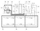
- FIG. 3 is a schematic diagram showing the overall configuration of an air conditioner according to Embodiment 2.
- FIG. 3 is a schematic diagram showing the overall configuration of an air conditioner according to Embodiment 2.
- the housing 1a is formed with an opening 40 for opening the external air passage 11A to the outside, and the opening 40 is opened and closed.
- An open damper 41 is provided for this purpose.
- the open damper 41 is closed when the air conditioner is in operation, that is, when the blower 3 is in operation, and is opened when it is stopped. That is, during operation, the air supply damper 12 is opened and the open damper 41 is closed, and during stoppage, the air supply damper 12 is closed and the open damper 41 is opened. Opening/closing control of the air supply damper 12 and the opening damper 41 is performed by a control device (not shown).
- a damper that closes when energized and opens when not energized it is desirable to use a damper that closes when energized and opens when not energized.
- a damper for example, a damper that is closed by being driven by a motor and opened by a spring when the current is removed may be used.
- the air conditioner closes the open damper 41 during operation, so that the air inside the outside-air-side air passage 11A does not leak to the outside through the open port 40. Therefore, the air conditioner is not affected by the provision of the opening 40 during operation, and exerts an air conditioning effect due to the normal air conditioning and ventilation operation and the influence of the ventilation operation.
- the open damper 41 is opened, and the inside and outside of the fan unit 1 communicate with each other through the opening 40 . Therefore, when refrigerant leakage occurs inside the housing 1 a when the air conditioner is stopped, the air conditioner can discharge the leaked refrigerant to the outside of the fan unit 1 through the opening 40 .
- the second embodiment is suitable for such a case, and the opening 40 that is opened when the operation is stopped is provided in the housing 1a. 12 and the air supply port 7 is discharged to the outside with priority from the open port 40. - ⁇ As a result, when there is a gap, leakage refrigerant can be prevented from entering the interior of the room 30 through the gap and generating a flammable region.
- the position of the open port 40 may be any position that allows the outside air passage 11A to be opened to the outside. From the point of view, it is desirable that the position be close to the air supply port 7 and the indoor heat exchanger 2 where refrigerant leakage occurs. As such a desirable position, FIG. 3 shows an example in which the open port 40 is provided between the indoor heat exchanger 2 and the air supply port 7 on the bottom surface of the housing 1a.
- the opening 40 it is desirable to install the opening 40 on the bottom surface of the housing 1a as shown in FIG. 3 in consideration of the intrusion of rain. In addition, it is desirable to add a net or the like to the opening 40 to prevent insects or small animals from entering.
- the air conditioner is provided with an outside air damper 15 and an exhaust damper 17 which are closed when the operation is stopped in the same manner as in the first embodiment, at the outside air port 6 and the exhaust port 9, so that insects or small animals from the outside air port 6 and the exhaust port 9 are provided. It is good also as a structure which prevents an intrusion, such as.
- the air conditioner may be provided with a return air damper 16 at the return air port 8 . In this way, when dampers are provided in all four openings, if the opening 40 is not provided, there is a possibility that a flammable area will be generated inside the housing 1a when the refrigerant leaks. However, since the air conditioner of Embodiment 2 is provided with the open port 40, it is possible to suppress the generation of a combustible region within the housing 1a when the refrigerant leaks.
- the air conditioner of Embodiment 2 can obtain the same effect as that of Embodiment 1, and has the opening 40 for opening the outside-air-side air passage 11A to the outside, and the opening 40 when the operation is stopped.
- the following effects can be obtained by providing the opening damper 41 for opening the . That is, the air conditioner of Embodiment 2 can efficiently discharge the refrigerant from the opening 40 to the outside of the housing 1a when the refrigerant leaks inside the housing 1a while the operation is stopped. It is possible to suppress the generation of a combustible region within 30 .
- Embodiment 3 differs from the first embodiment in the configuration of the housing 1a of the fan unit 1.
- FIG. Other configurations are the same as or equivalent to those of the first embodiment.
- the following description focuses on the configuration of the third embodiment that differs from the first embodiment, and the configurations not described in the third embodiment are the same as those of the first embodiment.
- FIG. 4 is a schematic diagram showing the overall configuration of an air conditioner according to Embodiment 3.
- FIG. 4 is a schematic diagram showing the overall configuration of an air conditioner according to Embodiment 3.
- a communication port 50 is formed in the partition wall 10 inside the housing 1a of the fan unit 1 to communicate the air passage 11A on the outside air side and the air passage 11B on the exhaust side.
- a penetrating damper 51 for opening and closing the communication port 50 is provided in the communication port 50 .
- the penetration damper 51 is closed when the air conditioner is in operation, that is, when the blower 3 is in operation, and is opened when the air conditioner is stopped. Opening/closing control of the penetrating damper 51 is performed by a control device (not shown).
- a damper that closes when energized and opens when not energized is preferably used as the penetrating damper 51 .
- a damper for example, a damper that is closed by a motor drive and opened by a spring when the current is removed may be used.
- a return air damper 16 for opening and closing the return air port 8 is provided at the return air port 8 .
- the air conditioner opens the supply air damper 12 and the return air damper 16 and closes the penetration damper 51 during operation.
- the air conditioner closes the supply air damper 12 and the return air damper 16 and opens the penetration damper 51 when stopped.
- the air conditioner stops the operation of the fan 3 is stopped, but the operation of the return fan 4 is continued.
- the air flow in the fan unit 1 during operation of the air conditioner is the same as in Embodiment 1, and the air conditioner exhibits the air conditioning effect of the normal air conditioning and ventilation operation or the ventilation operation during operation.
- the penetration damper 51 is opened as described above, the blower 3 is stopped, and the return fan 4 continues to operate.
- an airflow indicated by solid line arrows in FIG. 4 is generated in the fan unit 1 . That is, the outside air is taken into the outside air passage 11A in the housing 1a from the outside air port 6, passes through the total heat exchanger 5 and the indoor heat exchanger 2, and then flows through the communication port 50 into the exhaust side air passage 11B.
- the air conditioner if the refrigerant leaks from the indoor heat exchanger 2 when stopped, the airflow in the fan unit 1 diffuses the refrigerant in the housing 1a and discharges it to the outside of the room 30. No refrigerant reaches. Therefore, the air conditioner can suppress generation of a flammable region due to the refrigerant inside the room 30 even if refrigerant leakage occurs inside the housing 1a when operation is stopped.
- the position of the penetrating damper 51 is not limited to the position shown in FIG. 1, and may be the position shown in FIG.
- FIG. 5 is a schematic diagram showing a modification of the air conditioner according to Embodiment 3.
- FIG. 5 is a schematic diagram showing a modification of the air conditioner according to Embodiment 3.
- a communication port 50 and a penetration damper 51 are provided on the windward side of the indoor heat exchanger 2 .
- the airflow generated in the fan unit 1 by the operation of the return fan 4 when the operation is stopped becomes a flow passing through the outside air port 6 , the communication port 50 and the exhaust port 9 . That is, in the modified example, the airflow generated in the fan unit 1 when the operation is stopped does not pass through the indoor heat exchanger 2, so that the decrease in the flow rate due to the pressure loss can be suppressed.
- the leaked refrigerant can be efficiently stirred and exhausted, and the generation of a flammable region in the room 30 is minimized. becomes possible.
- the present disclosure can be used for an air conditioner that air-conditions a target room using a duct.
- 1 fan unit 1a housing, 2 indoor heat exchanger, 3 blower, 4 return air fan, 5 total heat exchanger, 5a casing, 5b honeycomb rotor, 6 outside air port, 7 air supply port, 8 return air port, 9 exhaust Mouth, 10 partition, 11A outside air passage, 11B exhaust air passage, 12 supply air damper, 13 supply air duct, 13a outlet, 14 return air duct, 14a suction port, 15 outside air damper, 16 return air damper, 17 Exhaust damper, 20 outdoor unit, 21 compressor, 22 four-way valve, 23 outdoor heat exchanger, 24 decompression device, 25 outdoor blower, 26 refrigerant piping, 30 indoor, 40 open port, 41 open damper, 50 communication port, 51 penetration damper.
Landscapes
- Engineering & Computer Science (AREA)
- Chemical & Material Sciences (AREA)
- Combustion & Propulsion (AREA)
- Mechanical Engineering (AREA)
- General Engineering & Computer Science (AREA)
- Air-Flow Control Members (AREA)
- Air Conditioning Control Device (AREA)
- Air Filters, Heat-Exchange Apparatuses, And Housings Of Air-Conditioning Units (AREA)
Priority Applications (4)
| Application Number | Priority Date | Filing Date | Title |
|---|---|---|---|
| CN202280049632.XA CN117693651A (zh) | 2021-07-23 | 2022-02-15 | 空调机 |
| AU2022313619A AU2022313619A1 (en) | 2021-07-23 | 2022-02-15 | Air conditioner |
| US18/564,196 US20240247824A1 (en) | 2021-07-23 | 2022-02-15 | Air-conditioning apparatus |
| JP2023536587A JPWO2023002653A1 (https=) | 2021-07-23 | 2022-02-15 |
Applications Claiming Priority (2)
| Application Number | Priority Date | Filing Date | Title |
|---|---|---|---|
| EP21425035.9A EP4123233B1 (en) | 2021-07-23 | 2021-07-23 | Air-conditioning apparatus |
| EP21425035.9 | 2021-07-23 |
Publications (1)
| Publication Number | Publication Date |
|---|---|
| WO2023002653A1 true WO2023002653A1 (ja) | 2023-01-26 |
Family
ID=77543458
Family Applications (1)
| Application Number | Title | Priority Date | Filing Date |
|---|---|---|---|
| PCT/JP2022/005925 Ceased WO2023002653A1 (ja) | 2021-07-23 | 2022-02-15 | 空気調和機 |
Country Status (6)
| Country | Link |
|---|---|
| US (1) | US20240247824A1 (https=) |
| EP (1) | EP4123233B1 (https=) |
| JP (1) | JPWO2023002653A1 (https=) |
| CN (1) | CN117693651A (https=) |
| AU (1) | AU2022313619A1 (https=) |
| WO (1) | WO2023002653A1 (https=) |
Cited By (3)
| Publication number | Priority date | Publication date | Assignee | Title |
|---|---|---|---|---|
| WO2024252670A1 (ja) * | 2023-06-09 | 2024-12-12 | 三菱電機株式会社 | 外気処理ユニットおよび空気調和機 |
| WO2025197133A1 (ja) * | 2024-03-22 | 2025-09-25 | 三菱電機株式会社 | 同時給排形換気装置 |
| WO2025215854A1 (ja) * | 2024-04-08 | 2025-10-16 | 三菱電機株式会社 | 換気装置 |
Citations (3)
| Publication number | Priority date | Publication date | Assignee | Title |
|---|---|---|---|---|
| JP2005188915A (ja) * | 2003-12-03 | 2005-07-14 | Daikin Ind Ltd | 調湿装置 |
| JP2011127847A (ja) * | 2009-12-18 | 2011-06-30 | Mitsubishi Electric Corp | 空気調和機 |
| KR101256780B1 (ko) * | 2013-01-24 | 2013-04-25 | (주)새한공조 | 직접 부하 제어 모드를 갖는 하이브리드 공조 시스템 |
Family Cites Families (4)
| Publication number | Priority date | Publication date | Assignee | Title |
|---|---|---|---|---|
| WO2015054303A1 (en) * | 2013-10-08 | 2015-04-16 | Johnson Controls Technology Company | Systems and methods for air conditioning a building using an energy recovery wheel |
| JP6851500B2 (ja) | 2017-11-15 | 2021-03-31 | 日立ジョンソンコントロールズ空調株式会社 | ダクト式空気調和機 |
| US10935454B2 (en) * | 2017-12-01 | 2021-03-02 | Johnson Controls Technology Company | Systems and methods for refrigerant leak management |
| WO2021050617A1 (en) * | 2019-09-13 | 2021-03-18 | Carrier Corporation | Hvac/r system with one or more leak mitigation dampers and method of diluting a leaked refrigerant in such a system |
-
2021
- 2021-07-23 EP EP21425035.9A patent/EP4123233B1/en active Active
-
2022
- 2022-02-15 WO PCT/JP2022/005925 patent/WO2023002653A1/ja not_active Ceased
- 2022-02-15 AU AU2022313619A patent/AU2022313619A1/en not_active Abandoned
- 2022-02-15 JP JP2023536587A patent/JPWO2023002653A1/ja active Pending
- 2022-02-15 CN CN202280049632.XA patent/CN117693651A/zh not_active Withdrawn
- 2022-02-15 US US18/564,196 patent/US20240247824A1/en active Pending
Patent Citations (3)
| Publication number | Priority date | Publication date | Assignee | Title |
|---|---|---|---|---|
| JP2005188915A (ja) * | 2003-12-03 | 2005-07-14 | Daikin Ind Ltd | 調湿装置 |
| JP2011127847A (ja) * | 2009-12-18 | 2011-06-30 | Mitsubishi Electric Corp | 空気調和機 |
| KR101256780B1 (ko) * | 2013-01-24 | 2013-04-25 | (주)새한공조 | 직접 부하 제어 모드를 갖는 하이브리드 공조 시스템 |
Cited By (3)
| Publication number | Priority date | Publication date | Assignee | Title |
|---|---|---|---|---|
| WO2024252670A1 (ja) * | 2023-06-09 | 2024-12-12 | 三菱電機株式会社 | 外気処理ユニットおよび空気調和機 |
| WO2025197133A1 (ja) * | 2024-03-22 | 2025-09-25 | 三菱電機株式会社 | 同時給排形換気装置 |
| WO2025215854A1 (ja) * | 2024-04-08 | 2025-10-16 | 三菱電機株式会社 | 換気装置 |
Also Published As
| Publication number | Publication date |
|---|---|
| CN117693651A (zh) | 2024-03-12 |
| US20240247824A1 (en) | 2024-07-25 |
| EP4123233B1 (en) | 2024-08-28 |
| EP4123233A1 (en) | 2023-01-25 |
| AU2022313619A1 (en) | 2023-12-14 |
| JPWO2023002653A1 (https=) | 2023-01-26 |
Similar Documents
| Publication | Publication Date | Title |
|---|---|---|
| CN107429934B (zh) | 利用侧空调装置以及包括该利用侧空调装置的空调装置 | |
| AU2013317055B2 (en) | Refrigeration cycle device | |
| JP5465338B2 (ja) | 空気調和装置 | |
| JP5452629B2 (ja) | 空気調和装置 | |
| WO2023002653A1 (ja) | 空気調和機 | |
| JP2015042930A (ja) | 空気調和装置および冷媒漏洩検知方法 | |
| JP2017075777A5 (https=) | ||
| JPWO2012049710A1 (ja) | 室外機および空気調和装置 | |
| JP5677461B2 (ja) | 冷凍サイクル装置の部品交換方法および冷凍サイクル装置 | |
| JPWO2002077535A1 (ja) | 空気調和装置及びその設置方法 | |
| JP2020183829A (ja) | 空調システム及び補助ファン | |
| AU2010364872A1 (en) | Part replacement method for refrigeration cycle device | |
| CN204704930U (zh) | 空调装置 | |
| EP3199881B1 (en) | Refrigeration cycle device | |
| JP7439517B2 (ja) | 送風装置及び送風システム | |
| JP2001012763A (ja) | 空調換気システム | |
| WO2016046965A1 (ja) | 冷凍サイクル装置 | |
| JP2024129524A (ja) | 冷凍サイクル装置 | |
| JP2008209045A (ja) | 換気空調装置 | |
| JP6399044B2 (ja) | 換気システム | |
| JPH1114178A (ja) | 空気調和装置 |
Legal Events
| Date | Code | Title | Description |
|---|---|---|---|
| 121 | Ep: the epo has been informed by wipo that ep was designated in this application |
Ref document number: 22845594 Country of ref document: EP Kind code of ref document: A1 |
|
| WWE | Wipo information: entry into national phase |
Ref document number: 2023536587 Country of ref document: JP |
|
| WWE | Wipo information: entry into national phase |
Ref document number: 18564196 Country of ref document: US |
|
| WWE | Wipo information: entry into national phase |
Ref document number: 2022313619 Country of ref document: AU Ref document number: AU2022313619 Country of ref document: AU |
|
| ENP | Entry into the national phase |
Ref document number: 2022313619 Country of ref document: AU Date of ref document: 20220215 Kind code of ref document: A |
|
| WWE | Wipo information: entry into national phase |
Ref document number: 202280049632.X Country of ref document: CN |
|
| NENP | Non-entry into the national phase |
Ref country code: DE |
|
| 122 | Ep: pct application non-entry in european phase |
Ref document number: 22845594 Country of ref document: EP Kind code of ref document: A1 |