WO2022269955A1 - アンテナ - Google Patents
アンテナ Download PDFInfo
- Publication number
- WO2022269955A1 WO2022269955A1 PCT/JP2021/048951 JP2021048951W WO2022269955A1 WO 2022269955 A1 WO2022269955 A1 WO 2022269955A1 JP 2021048951 W JP2021048951 W JP 2021048951W WO 2022269955 A1 WO2022269955 A1 WO 2022269955A1
- Authority
- WO
- WIPO (PCT)
- Prior art keywords
- electrodes
- antenna
- pair
- sheath
- electrode
- Prior art date
- Legal status (The legal status is an assumption and is not a legal conclusion. Google has not performed a legal analysis and makes no representation as to the accuracy of the status listed.)
- Ceased
Links
Images


Classifications
-
- H—ELECTRICITY
- H01—ELECTRIC ELEMENTS
- H01Q—ANTENNAS, i.e. RADIO AERIALS
- H01Q9/00—Electrically-short antennas having dimensions not more than twice the operating wavelength and consisting of conductive active radiating elements
- H01Q9/04—Resonant antennas
- H01Q9/16—Resonant antennas with feed intermediate between the extremities of the antenna, e.g. centre-fed dipole
- H01Q9/28—Conical, cylindrical, cage, strip, gauze, or like elements having an extended radiating surface; Elements comprising two conical surfaces having collinear axes and adjacent apices and fed by two-conductor transmission lines
-
- H—ELECTRICITY
- H01—ELECTRIC ELEMENTS
- H01Q—ANTENNAS, i.e. RADIO AERIALS
- H01Q1/00—Details of, or arrangements associated with, antennas
- H01Q1/04—Adaptation for subterranean or subaqueous use
Definitions
- This technology relates to antennas. More particularly, it relates to antennas for wireless communication over lossy media.
- a half-sheath dipole antenna with a part of the element exposed has been proposed as an antenna for wireless communication through a lossy medium. It is known that this half-sheath dipole antenna has higher impedance characteristics than a sheathless dipole antenna and a better transmission coefficient than a full-sheath dipole antenna (see, for example, Non-Patent Document 1).
- the transmission characteristics have been analyzed by electromagnetic field simulation, but the principle is not sufficiently clarified, and the optimal structure is not necessarily clear.
- This technology was created in view of this situation, and aims to optimize the structure and improve the transmission characteristics of antennas for wireless communication via lossy media.
- the present technology has been made to solve the above-described problems, and a first aspect thereof is to electrically connect at least a pair of electrodes, each of the at least a pair of electrodes, and its corresponding power supply terminal. and a sheath that encloses the wiring to be connected, and the minimum diameter of the electrode is larger than the width of the wiring. This brings about the effect of making the minimum diameter of the electrode connected to the wiring included in the sheath larger than the width of the wiring. As will be described later, the larger the diameter of the electrode, the better.
- the distance between the at least one pair of electrodes may be longer than the minimum diameter of the electrodes. As will be described later, the wider the distance between the electrodes, the better.
- each of the at least one pair of electrodes may be substantially spherical, spheroidal, or polyhedral. As will be described later, the closer the shape of the electrode is to a sphere, the better.
- the sheath may have a columnar shape extending in a direction in which the at least one pair of electrodes are connected. Further, the sheath may have a shape branching from the columnar shape.
- the sheath may contain air or pure water inside. Further, the sheath may contain a material having a conductivity of less than 1 S/m inside.
- each of the at least one pair of electrodes may have a coating on its surface.
- the magnitude of the impedance at the operating frequency between each of the at least one pair of electrodes and the external medium is smaller than the impedance when the coating is not provided.
- each of the at least one pair of electrodes may contain a material having a conductivity of less than 1 S/m inside.
- each of the at least one pair of electrodes may have a cavity inside.
- each of the at least one pair of electrodes may have at least one hole passing through the cavity.
- a transformer may be further provided in which the number of turns of the coil connected to the power supply terminal is smaller than that of the other coil. This brings about the effect of matching the impedance.
- a switching power amplifier connected to the power supply terminal may be further provided. This brings about the effect of matching the impedance.
- FIG. 1 is a diagram illustrating an overall configuration example of a wireless communication system according to an embodiment of the present technology
- FIG. It is a figure showing an example of shape of electrode 130 of antennas 101 and 102 in an embodiment of this art. It is a figure which shows the structural example of the wiring connection inside the electrode 130 in embodiment of this technique. It is a figure which shows the structural example of the cavity inside the electrode 130 in embodiment of this technique. It is a figure showing an example which provided two pairs of electrodes 130 in an embodiment of this art. It is a figure showing an equivalent circuit of antennas 101 and 102 in an embodiment of this art. It is a figure which shows the example of the electric field which generate
- Embodiment (antenna) 2. Application example (connection with wireless device)
- FIG. 1 is a diagram showing an overall configuration example of a wireless communication system according to an embodiment of the present technology.
- This wireless communication system includes a transmitting circuit 310 and a receiving circuit 320 as wireless devices for wireless communication. That is, the transmission circuit 310 transmits a radio signal to the reception circuit 320 and the reception circuit 320 receives the radio signal from the transmission circuit 310 .
- Transmitting circuit 310 and receiving circuit 320 are provided with antennas 101 and 102 respectively, and perform wireless communication via antennas 101 and 102 .
- Wireless communication between the transmitting circuit 310 and the receiving circuit 320 takes place over a lossy medium.
- the lossy medium is assumed to be, for example, seawater or a human body.
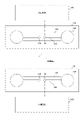
- Each of antennas 101 and 102 includes a pair of electrodes 130 and sheath 110 .
- the sheath portion 110 includes a pair of wires 120 that electrically connect the electrode 130 and the power supply terminal 190 corresponding to the electrode 130 .
- the sheath part 110 is also called a sheath.
- the sheath part 110 has, for example, a columnar shape extending in a direction connecting between the pair of electrodes 130 .
- a columnar shape a columnar shape or a prismatic shape is assumed.
- the shape may be branched from the middle of the columnar shape.
- the sheath 110 may contain a low-loss dielectric inside. Air, pure water, resin, glass, ceramic materials, etc. are assumed as low-loss dielectrics, for example.
- the low-loss dielectric inside sheath 110 may be made of a plurality of materials.
- a low-loss dielectric inside the sheath 110 air has the lowest loss, but is not suitable for environments with high water pressure.
- pure water is more suitable as a low-loss dielectric inside the sheath 110 in an environment with high water pressure.
- the low-loss dielectric inside the sheath 110 consideration must be given to prevent external media such as seawater from penetrating and coming into contact with the wiring 120 . be. However, as long as the medium does not come into contact with the wiring 120, it does not matter if the medium from the outside permeates inside the low-loss dielectric.
- the electrical conductivity of the low-loss dielectric inside the sheath 110 is less than 1 S/m, preferably less than 0.1 S/m.
- FIG. 2 is a diagram showing a shape example of the electrodes 130 of the antennas 101 and 102 according to the embodiment of the present technology.
- the shape of the electrode 130 it is desirable that it be spherical as shown in a in the figure, but any shape close to a sphere is sufficient.
- it may have a spheroidal shape, as indicated by b in FIG.
- the surface may not be smooth, and may have a polyhedral shape as shown in c in the figure.
- an icosahedron or more is desirable, but the polyhedron does not necessarily have to have 20 faces or more, and it does not have to be a regular polyhedron.
- the minimum diameter of the electrode 130 is larger than the width of the wiring 120 regardless of its shape.
- Materials for the electrodes 130 include highly corrosion-resistant metals such as copper (Cu), aluminum (Al), gold (Au), platinum (Pt), silver (Ag), and alloys thereof.
- the inside of the electrode 130 may be provided with a dielectric.
- the dielectric inside the electrode 130 may be made of a plurality of materials.
- the conductivity of the dielectric inside the electrode 130 is less than 1 S/m.
- the surface of the electrode 130 may be coated with a coating to prevent corrosion.
- the type of coating may be metal coating, inorganic coating, or organic coating.
- metal coating is applied to the surface of the electrode 130, for example, plating, metal spraying, metal diffusion, etc. are performed.
- the metal substance in this case it is desirable to use a material with high conductivity.
- an inorganic coating for example, coating or lining of glass, enamel, mortar, concrete, or the like is performed. Further, when the surface of the electrode 130 is coated with an organic substance, for example, coating or lining such as paint, rubber, or plastic is performed. However, it is preferable to make it as thin as possible or to choose a material with as high a dielectric constant as possible so that the capacitance generated by the coating is sufficiently large. Specifically, the magnitude of the impedance at the operating frequency between the electrode and the external medium is preferably smaller than the impedance when the surface of the electrode 130 is not coated.
- FIG. 3 is a diagram showing a structural example of wiring connection inside the electrode 130 according to the embodiment of the present technology.
- the wiring 120 connected to the power supply terminal 190 and the electrode 130 may be connected in any manner. That is, they may be connected at the front end as indicated by a in the figure, or may be connected at the farthest end as indicated by b in the figure. Moreover, as shown in c in the same figure, you may connect in the middle of the most near side and the farthest back. Furthermore, as indicated by d in the figure, the electrodes 130 may be connected at a plurality of points.
- FIG. 4 is a diagram showing a structural example of a cavity inside the electrode 130 according to the embodiment of the present technology.
- a cavity 138 may be provided inside the electrode 130 and at least one hole 139 passing through the cavity 138 may be provided in order to avoid deformation due to a pressure difference between the inside and outside of the electrode 130 .
- An external medium such as seawater enters the cavity 138 through this hole 139 . At this time, it is desirable to secure a low-loss material inside near the electrode 130 .
- a certain number of holes 139 passing through the cavity 138 may be provided. However, if the number of holes 139 is too large, the surface area of the electrode 130 is reduced and the electric field may be partially concentrated, leading to loss.
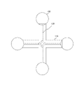
- FIG. 5 is a diagram showing an example in which two pairs of electrodes 130 are provided in the embodiment of the present technology.
- an electrode 130 is provided at each of the four ends of a cross-shaped sheath 110, and wiring 120 that electrically connects each electrode 130 to a power supply terminal 190 corresponding thereto is included. .
- FIG. 6 is a diagram showing equivalent circuits of antennas 101 and 102 in the embodiment of the present technology.
- the portion corresponding to the electrode 130 is assumed to have a cylindrical shape to formulate the impedance.
- This equivalent circuit of antennas 101 and 102 assumes a short-wavelength antenna in a lossy medium.
- Ls be the length corresponding to the sheath 110 and L be the length corresponding to the electrode 130 .
- rcyl be the radius of the cylindrical conductor corresponding to the electrode 130 .
- the columnar conductor antenna part is considered to be a series connection of an inductance 611 or 612 and a resistance 621 or 622.
- the reactance of the inductance 611 or 612 be Lhs/2.
- the resistance value of the resistor 621 or 622 be Rhs/2.
- an external medium such as seawater is considered to be a parallel connection of resistance 631 or 632 and capacitance 641 or 642.
- the conductance of the resistor 631 or 632 be 2Ghs.
- the capacitance of the capacitance 641 or 642 be 2Chs.
- the impedance Zhs seen from the power supply terminal 190 is obtained by the following equation.
- the conductance between the electrodes 130 is half that of a single electrode. Therefore, the conductance Ghs is given by the following equation. However, rell is defined as half the minor axis of an ellipse having the same area as a cylinder of length l and radius rcyl, and whose focus coordinates are ( ⁇ l/2, 0).
- the higher the impedance the lower the current under constant power conditions and the lower the charge on electrode 130 . This weakens the electric field and reduces efficiency.
- the surrounding electric field does not change under the condition of constant current, but the voltage increases, so the input power increases and the efficiency decreases. Therefore, under any condition, the efficiency decreases as the radius rcyl decreases. From this, it can be seen that the larger the diameter of the electrode 130, the better.
- FIG. 7 is a diagram showing an example of an electric field generated around the electrode 130 according to the embodiment of the present technology.
- the electric field around a conductor with the same charge is considered isotropic at a sufficient distance compared to the size of the conductor, regardless of the shape of the conductor.
- objects with the same surface area have the same charge density on the surface, so the density of electric lines of force near the conductor surface, that is, the electric field strength, is the same.
- the electric field intensity decreases in inverse proportion to the square of the distance in the sphere indicated by a in the figure.
- the electric field intensity drops gently in the vicinity of the conductor. Therefore, the loss will increase in the cylinder. Therefore, it can be seen that the shape of the electrode 130 is preferably spherical.
- FIG. 8 is a diagram showing an arrangement example of antennas 101 and 102 in the embodiment of the present technology.
- the transmission coefficient ⁇ between the antennas is expressed by the following equation.
- Kcorr is a correction coefficient for correcting the electrostatic field distribution to a high-frequency electric field distribution including the contribution of the displacement current and radiation.
- ⁇ is given by the following equation.
- the transmission coefficient ⁇ is inversely proportional to the square of the impedance. That is, the lower the impedance, the larger the transmission coefficient ⁇ . Since the transmission coefficient indicates the power efficiency during ideal transmission/reception matching, it can be seen that the lower the impedance, the better the power efficiency.
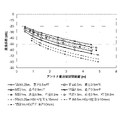
- FIG. 9 is a diagram showing an example of the relationship between the center-to-center distance of the electrodes 130 and the transmission coefficient in the embodiment of the present technology.
- FIG. 10 is a diagram showing an example of the relationship between the closest distance of the electrode 130 and the transmission coefficient in the embodiment of the present technology.
- the shape of the electrode 130 is (1) a sphere with a diameter of 0.5 m, (2) a spheroid with a major axis of 0.5 m and a minor axis of 0.2 m, and (3) a length of 0.5 m and a diameter of 0.01 m.
- 3 types of cylinders (HS in the figure) were assumed. The former two correspond to this embodiment, and the latter one corresponds to a conventional half-sheath dipole antenna.
- the transmission coefficient is larger in the order of (1) sphere, (2) spheroid, and (3) cylinder at both the center-to-center distance of the electrodes 130 and the closest distance of the electrodes 130 . Therefore, it is desirable that the electrode 130 be spherical also from this analysis result.
- the distance between the electrodes 130 is compared, it can be seen that the wider the distance, the better. Specifically, it is desirable that the distance between the electrodes 130 is longer than the minimum diameter of the electrodes 130 .
- this embodiment in which the electrodes are substantially spherical, has an improvement of about 15 dB. This corresponds to an area expansion of about ⁇ /3 in the far field region at the same power, and corresponds to a reduction in power consumption of about 15 dB (1/30 or less) at the same communication area.
- FIG. 11 is a diagram showing an example of the relationship between conductivity and transmission coefficient of the electrode 130 according to the embodiment of the present technology.
- FIG. 12 is a diagram showing an example of the relationship between the coating thickness of the electrode 130 and the transmission coefficient in the embodiment of the present technology.
- the electrode 130 is spherical with a radius of 0.25 m, the radius of the sheath 110 is 0.05 m, the length of the sheath 110 is 1 m, the radius of the wire 120 is 5 mm, and the distance between the antennas 101 and 102 is 2 m.
- FIG. 13 is a diagram showing a first impedance countermeasure example for the antenna according to the embodiment of the present technology.
- the transmission circuit 310 and the reception circuit 320 are provided with transformers 312 and 322, respectively, to step up and step down the voltage.
- a transmission signal input to transmission circuit 310 with an impedance of 50 ohms is amplified by power amplifier 311 (power amplifier) and supplied to transformer 312 .
- the number of turns of the coil connected to the power supply terminal 190 of the antenna 101 is smaller than the number of turns of the other coil connected to the power amplifier 311 .
- the impedance of the transmission signal input to the transmission circuit 310 and the signal output to the feeding terminal 190 of the antenna 101 are matched.
- the number of turns of the coil connected to the power supply terminal 190 of the antenna 102 is smaller than the number of turns of the other coil connected to the LNA (Low Noise Amplifier) 321 .
- the impedance of the signal input from the feeding terminal 190 of the antenna 102 and the received signal output from the receiving circuit 320 are matched.
- the impedance ratio can be 36:1.
- a 0.15 ohm antenna can appear to be 5.4 ohms when viewed from the amplifier side, and a good matching state with a 5 ohm amplifier can be realized.
- FIG. 14 is a diagram showing a second impedance countermeasure example for the antenna according to the embodiment of the present technology.
- the transmission circuit 310 is provided with a switching power amplifier (power amplifier) 313 .
- This power amplifier 313 can be realized by, for example, a class D amplifier or a class E amplifier. The output of this power amplifier 313 is supplied to the feeding terminal 190 of the antenna 101 .
- the switching power amplifier 313 is a constant voltage source, ideally the impedance is 0 ohms and the power efficiency is 100%.
- the impedance of antennas 101 and 102 is approximately 0.15 ohms at an operating frequency of 10 kHz, enabling operation with low impedance.
- transformers 312 and 322 and the power amplifier 313 are provided in the transmission circuit 310 or the like is shown, but these may be configured as a part of the antenna 101 or 102 .
- sheath structure In the above-described embodiment, the structure of the sheath portion 110 is assumed to be a columnar shape extending in the direction connecting the pair of electrodes 130 . However, the structure of the sheath 110 can be modified in various ways as described below.
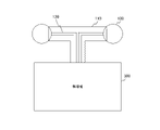
- FIG. 15 is a diagram showing another structural example of the sheath 110 according to the embodiment of the present technology.
- This example of the sheath 110 has a T-shaped structure that branches in the middle of the columnar shape. Thereby, the wiring 120 is configured to be pulled into the wireless device 300 .
- the wireless device 300 may be either the transmission circuit 310 or the reception circuit 320 described above.
- FIG. 16 is a diagram showing still another structural example of the sheath 110 according to the embodiment of the present technology.
- sheath 110 As still another structural example of the sheath 110, as shown in a in FIG. may be connected.
- the entire sheath 110 may be configured to be incorporated inside the wireless device 300 .
- the transmission characteristics of the antenna for wireless communication through a lossy medium can be improved. can be improved.
- the present technology can also have the following configuration.
- each of the at least one pair of electrodes has a polyhedral shape.
- each of the at least one pair of electrodes has a coating on its surface.
- the antenna according to (11), wherein the magnitude of the impedance at the operating frequency between each of the at least one pair of electrodes and an external medium is smaller than the impedance when the coating is not provided.
- each of the at least one pair of electrodes contains a material having a conductivity of less than 1 S/m.
- the antenna according to any one of (1) to (13), wherein each of the at least one pair of electrodes has a cavity inside.
- each of the at least one pair of electrodes has at least one hole penetrating the cavity.
Landscapes
- Details Of Aerials (AREA)
Priority Applications (4)
| Application Number | Priority Date | Filing Date | Title |
|---|---|---|---|
| CN202180099466.XA CN117501544A (zh) | 2021-06-23 | 2021-12-28 | 天线 |
| EP21947233.9A EP4362230A4 (en) | 2021-06-23 | 2021-12-28 | ANTENNA |
| JP2023529455A JP7732509B2 (ja) | 2021-06-23 | 2021-12-28 | アンテナ |
| US18/570,070 US12603437B2 (en) | 2021-06-23 | 2021-12-28 | Antenna |
Applications Claiming Priority (2)
| Application Number | Priority Date | Filing Date | Title |
|---|---|---|---|
| JP2021103942 | 2021-06-23 | ||
| JP2021-103942 | 2021-06-23 |
Publications (1)
| Publication Number | Publication Date |
|---|---|
| WO2022269955A1 true WO2022269955A1 (ja) | 2022-12-29 |
Family
ID=84543760
Family Applications (1)
| Application Number | Title | Priority Date | Filing Date |
|---|---|---|---|
| PCT/JP2021/048951 Ceased WO2022269955A1 (ja) | 2021-06-23 | 2021-12-28 | アンテナ |
Country Status (5)
| Country | Link |
|---|---|
| US (1) | US12603437B2 (https=) |
| EP (1) | EP4362230A4 (https=) |
| JP (1) | JP7732509B2 (https=) |
| CN (1) | CN117501544A (https=) |
| WO (1) | WO2022269955A1 (https=) |
Citations (3)
| Publication number | Priority date | Publication date | Assignee | Title |
|---|---|---|---|---|
| JP2008211778A (ja) * | 2007-02-01 | 2008-09-11 | Canon Inc | アンテナ素子 |
| CN207542389U (zh) * | 2017-12-04 | 2018-06-26 | 深圳市威嘉诚科技有限公司 | 一种全向天线 |
| JP2019533260A (ja) * | 2016-08-26 | 2019-11-14 | シャンハイ イネサ インテリジェント エレクトロニクス カンパニー リミテッドShanghai Inesa Intelligent Electronics Co., Ltd. | タイヤ埋込型電子タグ及び組立プロセス |
Family Cites Families (10)
| Publication number | Priority date | Publication date | Assignee | Title |
|---|---|---|---|---|
| CA401693A (en) | 1941-12-23 | Alexander Schelkunoff Sergei | Ultra-short wave radio system | |
| DE1109748B (de) | 1958-12-10 | 1961-06-29 | Siemens Ag | Antennenanordnung fuer kurze und sehr kurze elektromagnetische Wellen |
| US5521610A (en) * | 1993-09-17 | 1996-05-28 | Trimble Navigation Limited | Curved dipole antenna with center-post amplifier |
| US6424309B1 (en) * | 2000-02-18 | 2002-07-23 | Telecommunications Research Laboratories | Broadband compact slot dipole/monopole and electric dipole/monopole combined antenna |
| JP2005051747A (ja) * | 2003-07-14 | 2005-02-24 | Ngk Spark Plug Co Ltd | アンテナ装置およびその製造方法 |
| JP2005124030A (ja) | 2003-10-20 | 2005-05-12 | Nippon Telegr & Teleph Corp <Ntt> | 球状ダイポールアンテナ |
| US7327318B2 (en) * | 2006-02-28 | 2008-02-05 | Mti Wireless Edge, Ltd. | Ultra wide band flat antenna |
| US8816484B2 (en) | 2007-02-09 | 2014-08-26 | Semiconductor Energy Laboratory Co., Ltd. | Semiconductor device |
| CN110176668B (zh) * | 2019-05-22 | 2021-01-15 | 维沃移动通信有限公司 | 天线单元和电子设备 |
| US10985464B2 (en) * | 2019-07-31 | 2021-04-20 | Verily Life Sciences Llc | Miniaturized inductive loop antenna with distributed reactive loads |
-
2021
- 2021-12-28 US US18/570,070 patent/US12603437B2/en active Active
- 2021-12-28 CN CN202180099466.XA patent/CN117501544A/zh active Pending
- 2021-12-28 WO PCT/JP2021/048951 patent/WO2022269955A1/ja not_active Ceased
- 2021-12-28 EP EP21947233.9A patent/EP4362230A4/en active Pending
- 2021-12-28 JP JP2023529455A patent/JP7732509B2/ja active Active
Patent Citations (3)
| Publication number | Priority date | Publication date | Assignee | Title |
|---|---|---|---|---|
| JP2008211778A (ja) * | 2007-02-01 | 2008-09-11 | Canon Inc | アンテナ素子 |
| JP2019533260A (ja) * | 2016-08-26 | 2019-11-14 | シャンハイ イネサ インテリジェント エレクトロニクス カンパニー リミテッドShanghai Inesa Intelligent Electronics Co., Ltd. | タイヤ埋込型電子タグ及び組立プロセス |
| CN207542389U (zh) * | 2017-12-04 | 2018-06-26 | 深圳市威嘉诚科技有限公司 | 一种全向天线 |
Non-Patent Citations (2)
| Title |
|---|
| H. SATO ET AL.: "Dipole antenna with sheath-cover for seawater use", 2017 INTERNATIONAL SYMPOSIUM ON ANTENNAS AND PROPAGATION (ISAP, vol. 1376, 2017, pages 1 - 2, XP033285312, DOI: 10.1109/ISANP.2017.8228941 |
| See also references of EP4362230A4 |
Also Published As
| Publication number | Publication date |
|---|---|
| EP4362230A4 (en) | 2024-10-23 |
| JPWO2022269955A1 (https=) | 2022-12-29 |
| EP4362230A1 (en) | 2024-05-01 |
| JP7732509B2 (ja) | 2025-09-02 |
| CN117501544A (zh) | 2024-02-02 |
| US20240275056A1 (en) | 2024-08-15 |
| US12603437B2 (en) | 2026-04-14 |
Similar Documents
| Publication | Publication Date | Title |
|---|---|---|
| CN110676575B (zh) | 一种小型化的高增益双频wifi天线 | |
| US7626558B2 (en) | Wideband antenna | |
| JP4098818B2 (ja) | スロット付き円筒アンテナ | |
| TW201001811A (en) | Folded conical antenna and associated methods | |
| US20080211727A1 (en) | System and apparatus for transmitting a surface wave over a single conductor | |
| JP3123386B2 (ja) | アンテナ一体型ストリップラインケーブル | |
| JP2007110723A (ja) | 広帯域アンテナおよびその製造方法 | |
| US20100033391A1 (en) | Horn Antenna with Integrated Impedance Matching Network for Improved Operating Frequency Range | |
| US7764242B2 (en) | Broadband antenna system | |
| CN1237278A (zh) | 用于便携无线电设备的小型天线 | |
| US6486849B2 (en) | Small L-band antenna | |
| CN100483847C (zh) | 不平衡天线 | |
| CN113036457B (zh) | 一种基于微波输能的柔性天线阵列 | |
| CN107785666A (zh) | 基于siw技术的h面喇叭天线 | |
| CN104183914B (zh) | 无线耳机及用于无线耳机的天线 | |
| CN206040960U (zh) | 电小平面惠更斯源天线 | |
| JP7732509B2 (ja) | アンテナ | |
| RU2357337C1 (ru) | Плоская резонаторная антенна (варианты) | |
| CN103943948A (zh) | 用于入耳式无线耳机的可折叠pcb板螺旋天线 | |
| TWI268011B (en) | Dual-band or single-band dipole antenna | |
| CN216085294U (zh) | 一种小型化磁天线 | |
| CN210778973U (zh) | 一种星载vhf天线 | |
| CN110943285B (zh) | 一种星载vhf天线 | |
| CN100364171C (zh) | 平面式双频单极天线 | |
| CN207165754U (zh) | 增强型芯片天线结构 |
Legal Events
| Date | Code | Title | Description |
|---|---|---|---|
| 121 | Ep: the epo has been informed by wipo that ep was designated in this application |
Ref document number: 21947233 Country of ref document: EP Kind code of ref document: A1 |
|
| WWE | Wipo information: entry into national phase |
Ref document number: 2023529455 Country of ref document: JP |
|
| WWE | Wipo information: entry into national phase |
Ref document number: 18570070 Country of ref document: US |
|
| WWE | Wipo information: entry into national phase |
Ref document number: 202180099466.X Country of ref document: CN |
|
| WWE | Wipo information: entry into national phase |
Ref document number: 2021947233 Country of ref document: EP |
|
| NENP | Non-entry into the national phase |
Ref country code: DE |
|
| ENP | Entry into the national phase |
Ref document number: 2021947233 Country of ref document: EP Effective date: 20240123 |