WO2022269658A1 - 負荷時タップ切換器のタップ選択器 - Google Patents
負荷時タップ切換器のタップ選択器 Download PDFInfo
- Publication number
- WO2022269658A1 WO2022269658A1 PCT/JP2021/023316 JP2021023316W WO2022269658A1 WO 2022269658 A1 WO2022269658 A1 WO 2022269658A1 JP 2021023316 W JP2021023316 W JP 2021023316W WO 2022269658 A1 WO2022269658 A1 WO 2022269658A1
- Authority
- WO
- WIPO (PCT)
- Prior art keywords
- shaft
- rollers
- pair
- roller
- case
- Prior art date
- Legal status (The legal status is an assumption and is not a legal conclusion. Google has not performed a legal analysis and makes no representation as to the accuracy of the status listed.)
- Ceased
Links
Images




Classifications
-
- H—ELECTRICITY
- H01—ELECTRIC ELEMENTS
- H01F—MAGNETS; INDUCTANCES; TRANSFORMERS; SELECTION OF MATERIALS FOR THEIR MAGNETIC PROPERTIES
- H01F29/00—Variable transformers or inductances not covered by group H01F21/00
- H01F29/02—Variable transformers or inductances not covered by group H01F21/00 with tappings on coil or winding; with provision for rearrangement or interconnection of windings
Definitions
- the problem to be solved by the present invention is to provide a tap selector for an on-load tap changer that can reduce the adjustment process of the tap selector.
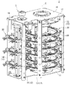
- the tap selector of the on-load tap changer of the embodiment has a holding member, a case, a shaft, a roller, and a bottom plate.
- a holding member holds the movable contact.
- a case is attached to the holding member.
- a shaft is attached to the case.
- the roller is rotatable around said shaft.
- the bottom plate has a guide portion that guides the roller.
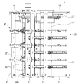
- the main switching device 20 includes a main fixed unit 21 (fixed portion) and a main movable unit 22 (movable portion) movable with respect to the main fixed unit 21 .
- the main fixing units 21 are provided in the same number as the collector rings 18 (for example, six in this embodiment).
- the number of main fixing units 21 corresponding to the three phases of U phase, V phase and W phase (for example, two for each phase in this embodiment, total six) is provided.
- a plurality of main fixing units 21 are fixed to the main strut 13 at substantially the same intervals in the vertical direction.
- the movable plate 60 extends in the radial direction of the current collection ring 18 so as to straddle the current collection ring 18 and the fixed plate 40 .
- the inner portion of the movable plate 60 overlaps the current collection ring 18 when viewed from above and below.
- the outer portion of the movable plate 60 overlaps the fixed plate 40 when viewed from above and below.
- a pair of holding members 90 are provided with the main movable unit 22 interposed therebetween.
- a pair of holding members 90 are arranged on both sides of the main movable unit 22 in the circumferential direction of the collector ring 18 .
- the main movable unit 22 is vertically movable by being held by a pair of holding members 90 .
- FIG. 5 is a perspective view showing part of the tap selector 2 of the embodiment.
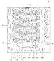
- the bottom plate 11 has guide grooves 110 that guide the moving mechanism 100 .
- the guide groove 110 is formed in an annular shape when viewed from above.
- the guide groove 110 has an annular shape concentric with the central axis C of the main switch 20 (the central axis C of the column 19).
- the moving mechanism 100 can move in the direction along the guide groove 110 (the arrow V3 direction in FIG. 5) via the holding member 90 .
- the direction of arrow V3 in FIG. 5 is the same as the direction of arrow V1 in FIG.
- the direction along the central axis C of the main switch 20 will be referred to as the "axial direction of the main switch 20"
- the direction orthogonal to the axial direction of the main switch 20 will be referred to as the "radial direction of the main switch 20”
- the direction along the central axis C The peripheral direction is defined as "the peripheral direction of the main switch 20”.
- the axial direction of the main switch 20 is a direction (vertical direction) perpendicular to the horizontal direction.
- the case 101 has a female threaded portion 124 into which a bolt 123 can be screwed.
- the holding member 90 has a bolt hole 91 through which the bolt 123 can be inserted. According to this configuration, the case 101 can be attached to the holding member 90 by inserting the bolt 123 into the bolt hole 91 of the holding member 90 and screwing it into the female threaded portion 124 of the case 101 . Therefore, no special fixing members or special jigs are required. Therefore, the number of assembly man-hours can be reduced.
- FIG. 13 is a cross-sectional perspective view of a movable contact moving mechanism 200 of a comparative example.
- the movable contact moving mechanism 200 of the comparative example includes a sphere 202 built in a case 201 .
- the case 201 of the comparative example is provided with a set screw 205 for size adjustment.
- the bottom plate 209 of the comparative example has guide grooves 210 that guide the spheres 202 .
- Guide groove 210 is formed in an annular shape when viewed from above.
- the moving mechanism 200 can move in the direction along the guide groove 210 via the holding member 90 .
- FIG. 14 is a side view of the connecting wire 206 of the movable contact moving mechanism 200 of the comparative example.
- the movable contact moving mechanism 200 of the comparative example has a connection line 206 for obtaining a potential.
- One end of the connection line 206 is connected to the upper portion of the case 201 .
- the other end of the connection line 206 is arranged near the upper surface of the bottom plate 209 .
- installation of the connection line 206 requires material cost. Therefore, it is required to reduce the material cost.
- the roller 103 is rotatable around the shaft 102, so that the contact state of the roller 103 with the guide portions 113 and 114 is maintained constant. Therefore, it is not necessary to adjust the contact state of the roller 103 .
- the roller 103 does not come off the guide groove 110, the quality is stable.
- the movement of the moving mechanism 100 does not slow down. Therefore, it is possible to reduce the adjustment process of the tap selector 2, reduce the number of assembly man-hours, and improve the quality.
- the case 101, the rollers 103 and the bottom plate 11 are made of metal.
- a pair of rollers are provided facing each other in the axial direction of the shaft.
- the tap selector includes a biasing member provided between a pair of rollers.
- the biasing member biases the pair of rollers toward the guide.
- the configuration of the rollers is not limited to this.
- a pair of rollers may not be provided.
- the tap selector may not have a biasing member.
- only one roller may be provided.
- the rollers may contact the guides under the action of gravity.
- the number of rollers installed and the manner of contact with the guide portion can be changed according to the required specifications.
Landscapes
- Engineering & Computer Science (AREA)
- Power Engineering (AREA)
- Transmission Devices (AREA)
Priority Applications (2)
| Application Number | Priority Date | Filing Date | Title |
|---|---|---|---|
| PCT/JP2021/023316 WO2022269658A1 (ja) | 2021-06-21 | 2021-06-21 | 負荷時タップ切換器のタップ選択器 |
| JP2023529192A JP7532662B2 (ja) | 2021-06-21 | 2021-06-21 | 負荷時タップ切換器のタップ選択器 |
Applications Claiming Priority (1)
| Application Number | Priority Date | Filing Date | Title |
|---|---|---|---|
| PCT/JP2021/023316 WO2022269658A1 (ja) | 2021-06-21 | 2021-06-21 | 負荷時タップ切換器のタップ選択器 |
Publications (1)
| Publication Number | Publication Date |
|---|---|
| WO2022269658A1 true WO2022269658A1 (ja) | 2022-12-29 |
Family
ID=84544285
Family Applications (1)
| Application Number | Title | Priority Date | Filing Date |
|---|---|---|---|
| PCT/JP2021/023316 Ceased WO2022269658A1 (ja) | 2021-06-21 | 2021-06-21 | 負荷時タップ切換器のタップ選択器 |
Country Status (2)
| Country | Link |
|---|---|
| JP (1) | JP7532662B2 (https=) |
| WO (1) | WO2022269658A1 (https=) |
Citations (3)
| Publication number | Priority date | Publication date | Assignee | Title |
|---|---|---|---|---|
| JPS59195405A (ja) * | 1983-04-19 | 1984-11-06 | Kazuo Fujita | キヤスタ車輪 |
| JPH11329870A (ja) * | 1998-05-18 | 1999-11-30 | Toshiba Corp | 負荷時タップ切換器 |
| CN1534189A (zh) * | 2003-04-01 | 2004-10-06 | 王庚法 | 一种空气动力发电装置 |
Family Cites Families (1)
| Publication number | Priority date | Publication date | Assignee | Title |
|---|---|---|---|---|
| JPS62263620A (ja) * | 1986-05-12 | 1987-11-16 | Toshiba Corp | 負荷時タツプ切換器 |
-
2021
- 2021-06-21 JP JP2023529192A patent/JP7532662B2/ja active Active
- 2021-06-21 WO PCT/JP2021/023316 patent/WO2022269658A1/ja not_active Ceased
Patent Citations (3)
| Publication number | Priority date | Publication date | Assignee | Title |
|---|---|---|---|---|
| JPS59195405A (ja) * | 1983-04-19 | 1984-11-06 | Kazuo Fujita | キヤスタ車輪 |
| JPH11329870A (ja) * | 1998-05-18 | 1999-11-30 | Toshiba Corp | 負荷時タップ切換器 |
| CN1534189A (zh) * | 2003-04-01 | 2004-10-06 | 王庚法 | 一种空气动力发电装置 |
Also Published As
| Publication number | Publication date |
|---|---|
| JP7532662B2 (ja) | 2024-08-13 |
| JPWO2022269658A1 (https=) | 2022-12-29 |
Similar Documents
| Publication | Publication Date | Title |
|---|---|---|
| JP7279264B2 (ja) | 負荷時タップ切換器のタップ選択器の切換機構 | |
| CN102410395A (zh) | 电子膨胀阀 | |
| WO2022269658A1 (ja) | 負荷時タップ切換器のタップ選択器 | |
| KR20230048567A (ko) | 부하시 탭 절환기용 스위칭 시스템, 부하시 탭 절환기 및 부하시 탭 절환기의 탭 연결을 스위칭하는 방법 | |
| WO2023001962A1 (en) | On-load tap changer with positioning device and method for assembling an on-load tap changer | |
| CN216161908U (zh) | 腔体滤波器 | |
| WO2022085288A1 (ja) | 負荷時タップ切換器のタップ選択器 | |
| JP7358641B2 (ja) | 負荷時タップ切換器のタップ選択器 | |
| CN112108822B (zh) | 一种用于真空开关管焊接的固定装置 | |
| WO2022083902A1 (en) | Switching system for an on-load tap changer, on-load tap changer and method for switching a tap connection of an on-load tap changer | |
| CN111842980B (zh) | 一种伺服电机转动配件制造加工工艺 | |
| KR102322881B1 (ko) | 맨드렐 장치 | |
| CN105690248A (zh) | 一种双平面磨床的主轴进给装置 | |
| GB2035694A (en) | Selector switch for a tapped transformer | |
| CN117182775A (zh) | 一种用于绝缘轴承外圈涂层磨削的夹紧装置 | |
| CN113753740B (zh) | 一种向心关节轴承内圈孔吊装芯轴的装置及其方法 | |
| CN109378255B (zh) | 一种继电器 | |
| CN208067706U (zh) | 滚针轴承的卡簧压装装置 | |
| CN115815645B (zh) | 一种辊芯加工工装及加工方法 | |
| JP4939566B2 (ja) | タップ選択器 | |
| EP4517794A1 (en) | Contact ring unit for a tap changer and tap changer | |
| CN223793419U (zh) | 一种筛鼓固定环定位装置 | |
| CN112676720B (zh) | 用于激光无缝焊接的夹具 | |
| CN211101244U (zh) | 一种外径尺寸可调节的夹具 | |
| JPH11329870A (ja) | 負荷時タップ切換器 |
Legal Events
| Date | Code | Title | Description |
|---|---|---|---|
| 121 | Ep: the epo has been informed by wipo that ep was designated in this application |
Ref document number: 21946949 Country of ref document: EP Kind code of ref document: A1 |
|
| ENP | Entry into the national phase |
Ref document number: 2023529192 Country of ref document: JP Kind code of ref document: A |
|
| NENP | Non-entry into the national phase |
Ref country code: DE |
|
| 122 | Ep: pct application non-entry in european phase |
Ref document number: 21946949 Country of ref document: EP Kind code of ref document: A1 |