WO2022265055A1 - 反応装置、及び、ビニル系重合体の製造方法 - Google Patents
反応装置、及び、ビニル系重合体の製造方法 Download PDFInfo
- Publication number
- WO2022265055A1 WO2022265055A1 PCT/JP2022/024028 JP2022024028W WO2022265055A1 WO 2022265055 A1 WO2022265055 A1 WO 2022265055A1 JP 2022024028 W JP2022024028 W JP 2022024028W WO 2022265055 A1 WO2022265055 A1 WO 2022265055A1
- Authority
- WO
- WIPO (PCT)
- Prior art keywords
- polymerization
- cooling pipe
- meandering
- baffle
- reactor
- Prior art date
- Legal status (The legal status is an assumption and is not a legal conclusion. Google has not performed a legal analysis and makes no representation as to the accuracy of the status listed.)
- Ceased
Links
Images


Classifications
-
- B—PERFORMING OPERATIONS; TRANSPORTING
- B01—PHYSICAL OR CHEMICAL PROCESSES OR APPARATUS IN GENERAL
- B01F—MIXING, e.g. DISSOLVING, EMULSIFYING OR DISPERSING
- B01F27/00—Mixers with rotary stirring devices in fixed receptacles; Kneaders
- B01F27/05—Stirrers
- B01F27/11—Stirrers characterised by the configuration of the stirrers
- B01F27/19—Stirrers with two or more mixing elements mounted in sequence on the same axis
- B01F27/191—Stirrers with two or more mixing elements mounted in sequence on the same axis with similar elements
-
- B—PERFORMING OPERATIONS; TRANSPORTING
- B01—PHYSICAL OR CHEMICAL PROCESSES OR APPARATUS IN GENERAL
- B01F—MIXING, e.g. DISSOLVING, EMULSIFYING OR DISPERSING
- B01F27/00—Mixers with rotary stirring devices in fixed receptacles; Kneaders
- B01F27/80—Mixers with rotary stirring devices in fixed receptacles; Kneaders with stirrers rotating about a substantially vertical axis
- B01F27/86—Mixers with rotary stirring devices in fixed receptacles; Kneaders with stirrers rotating about a substantially vertical axis co-operating with deflectors or baffles fixed to the receptacle
-
- B—PERFORMING OPERATIONS; TRANSPORTING
- B01—PHYSICAL OR CHEMICAL PROCESSES OR APPARATUS IN GENERAL
- B01F—MIXING, e.g. DISSOLVING, EMULSIFYING OR DISPERSING
- B01F27/00—Mixers with rotary stirring devices in fixed receptacles; Kneaders
- B01F27/80—Mixers with rotary stirring devices in fixed receptacles; Kneaders with stirrers rotating about a substantially vertical axis
- B01F27/90—Mixers with rotary stirring devices in fixed receptacles; Kneaders with stirrers rotating about a substantially vertical axis with paddles or arms
-
- B—PERFORMING OPERATIONS; TRANSPORTING
- B01—PHYSICAL OR CHEMICAL PROCESSES OR APPARATUS IN GENERAL
- B01F—MIXING, e.g. DISSOLVING, EMULSIFYING OR DISPERSING
- B01F35/00—Accessories for mixers; Auxiliary operations or auxiliary devices; Parts or details of general application
- B01F35/50—Mixing receptacles
- B01F35/53—Mixing receptacles characterised by the configuration of the interior, e.g. baffles for facilitating the mixing of components
- B01F35/531—Mixing receptacles characterised by the configuration of the interior, e.g. baffles for facilitating the mixing of components with baffles, plates or bars on the wall or the bottom
- B01F35/5312—Mixing receptacles characterised by the configuration of the interior, e.g. baffles for facilitating the mixing of components with baffles, plates or bars on the wall or the bottom with vertical baffles mounted on the walls
-
- B—PERFORMING OPERATIONS; TRANSPORTING
- B01—PHYSICAL OR CHEMICAL PROCESSES OR APPARATUS IN GENERAL
- B01F—MIXING, e.g. DISSOLVING, EMULSIFYING OR DISPERSING
- B01F35/00—Accessories for mixers; Auxiliary operations or auxiliary devices; Parts or details of general application
- B01F35/90—Heating or cooling systems
- B01F35/93—Heating or cooling systems arranged inside the receptacle
-
- B—PERFORMING OPERATIONS; TRANSPORTING
- B01—PHYSICAL OR CHEMICAL PROCESSES OR APPARATUS IN GENERAL
- B01J—CHEMICAL OR PHYSICAL PROCESSES, e.g. CATALYSIS OR COLLOID CHEMISTRY; THEIR RELEVANT APPARATUS
- B01J19/00—Chemical, physical or physico-chemical processes in general; Their relevant apparatus
- B01J19/0006—Controlling or regulating processes
- B01J19/0013—Controlling the temperature of the process
-
- B—PERFORMING OPERATIONS; TRANSPORTING
- B01—PHYSICAL OR CHEMICAL PROCESSES OR APPARATUS IN GENERAL
- B01J—CHEMICAL OR PHYSICAL PROCESSES, e.g. CATALYSIS OR COLLOID CHEMISTRY; THEIR RELEVANT APPARATUS
- B01J19/00—Chemical, physical or physico-chemical processes in general; Their relevant apparatus
- B01J19/0053—Details of the reactor
- B01J19/006—Baffles
-
- B—PERFORMING OPERATIONS; TRANSPORTING
- B01—PHYSICAL OR CHEMICAL PROCESSES OR APPARATUS IN GENERAL
- B01J—CHEMICAL OR PHYSICAL PROCESSES, e.g. CATALYSIS OR COLLOID CHEMISTRY; THEIR RELEVANT APPARATUS
- B01J19/00—Chemical, physical or physico-chemical processes in general; Their relevant apparatus
- B01J19/0053—Details of the reactor
- B01J19/0066—Stirrers
-
- B—PERFORMING OPERATIONS; TRANSPORTING
- B01—PHYSICAL OR CHEMICAL PROCESSES OR APPARATUS IN GENERAL
- B01J—CHEMICAL OR PHYSICAL PROCESSES, e.g. CATALYSIS OR COLLOID CHEMISTRY; THEIR RELEVANT APPARATUS
- B01J19/00—Chemical, physical or physico-chemical processes in general; Their relevant apparatus
- B01J19/18—Stationary reactors having moving elements inside
-
- B—PERFORMING OPERATIONS; TRANSPORTING
- B01—PHYSICAL OR CHEMICAL PROCESSES OR APPARATUS IN GENERAL
- B01J—CHEMICAL OR PHYSICAL PROCESSES, e.g. CATALYSIS OR COLLOID CHEMISTRY; THEIR RELEVANT APPARATUS
- B01J19/00—Chemical, physical or physico-chemical processes in general; Their relevant apparatus
- B01J19/24—Stationary reactors without moving elements inside
- B01J19/2415—Tubular reactors
-
- C—CHEMISTRY; METALLURGY
- C08—ORGANIC MACROMOLECULAR COMPOUNDS; THEIR PREPARATION OR CHEMICAL WORKING-UP; COMPOSITIONS BASED THEREON
- C08F—MACROMOLECULAR COMPOUNDS OBTAINED BY REACTIONS ONLY INVOLVING CARBON-TO-CARBON UNSATURATED BONDS
- C08F114/00—Homopolymers of compounds having one or more unsaturated aliphatic radicals, each having only one carbon-to-carbon double bond, and at least one being terminated by a halogen
- C08F114/02—Monomers containing chlorine
- C08F114/04—Monomers containing two carbon atoms
- C08F114/06—Vinyl chloride
-
- C—CHEMISTRY; METALLURGY
- C08—ORGANIC MACROMOLECULAR COMPOUNDS; THEIR PREPARATION OR CHEMICAL WORKING-UP; COMPOSITIONS BASED THEREON
- C08F—MACROMOLECULAR COMPOUNDS OBTAINED BY REACTIONS ONLY INVOLVING CARBON-TO-CARBON UNSATURATED BONDS
- C08F14/00—Homopolymers and copolymers of compounds having one or more unsaturated aliphatic radicals, each having only one carbon-to-carbon double bond, and at least one being terminated by a halogen
- C08F14/02—Monomers containing chlorine
- C08F14/04—Monomers containing two carbon atoms
- C08F14/06—Vinyl chloride
-
- C—CHEMISTRY; METALLURGY
- C08—ORGANIC MACROMOLECULAR COMPOUNDS; THEIR PREPARATION OR CHEMICAL WORKING-UP; COMPOSITIONS BASED THEREON
- C08F—MACROMOLECULAR COMPOUNDS OBTAINED BY REACTIONS ONLY INVOLVING CARBON-TO-CARBON UNSATURATED BONDS
- C08F2/00—Processes of polymerisation
- C08F2/01—Processes of polymerisation characterised by special features of the polymerisation apparatus used
-
- C—CHEMISTRY; METALLURGY
- C08—ORGANIC MACROMOLECULAR COMPOUNDS; THEIR PREPARATION OR CHEMICAL WORKING-UP; COMPOSITIONS BASED THEREON
- C08F—MACROMOLECULAR COMPOUNDS OBTAINED BY REACTIONS ONLY INVOLVING CARBON-TO-CARBON UNSATURATED BONDS
- C08F2/00—Processes of polymerisation
- C08F2/12—Polymerisation in non-solvents
- C08F2/16—Aqueous medium
- C08F2/18—Suspension polymerisation
- C08F2/20—Suspension polymerisation with the aid of macromolecular dispersing agents
-
- B—PERFORMING OPERATIONS; TRANSPORTING
- B01—PHYSICAL OR CHEMICAL PROCESSES OR APPARATUS IN GENERAL
- B01F—MIXING, e.g. DISSOLVING, EMULSIFYING OR DISPERSING
- B01F35/00—Accessories for mixers; Auxiliary operations or auxiliary devices; Parts or details of general application
- B01F35/90—Heating or cooling systems
- B01F2035/98—Cooling
-
- B—PERFORMING OPERATIONS; TRANSPORTING
- B01—PHYSICAL OR CHEMICAL PROCESSES OR APPARATUS IN GENERAL
- B01F—MIXING, e.g. DISSOLVING, EMULSIFYING OR DISPERSING
- B01F2101/00—Mixing characterised by the nature of the mixed materials or by the application field
- B01F2101/2204—Mixing chemical components in generals in order to improve chemical treatment or reactions, independently from the specific application
-
- B—PERFORMING OPERATIONS; TRANSPORTING
- B01—PHYSICAL OR CHEMICAL PROCESSES OR APPARATUS IN GENERAL
- B01J—CHEMICAL OR PHYSICAL PROCESSES, e.g. CATALYSIS OR COLLOID CHEMISTRY; THEIR RELEVANT APPARATUS
- B01J2208/00—Processes carried out in the presence of solid particles; Reactors therefor
- B01J2208/00796—Details of the reactor or of the particulate material
- B01J2208/00823—Mixing elements
- B01J2208/00831—Stationary elements
- B01J2208/0084—Stationary elements inside the bed, e.g. baffles
-
- B—PERFORMING OPERATIONS; TRANSPORTING
- B01—PHYSICAL OR CHEMICAL PROCESSES OR APPARATUS IN GENERAL
- B01J—CHEMICAL OR PHYSICAL PROCESSES, e.g. CATALYSIS OR COLLOID CHEMISTRY; THEIR RELEVANT APPARATUS
- B01J2219/00—Chemical, physical or physico-chemical processes in general; Their relevant apparatus
- B01J2219/00049—Controlling or regulating processes
- B01J2219/00051—Controlling the temperature
- B01J2219/00074—Controlling the temperature by indirect heating or cooling employing heat exchange fluids
- B01J2219/00076—Controlling the temperature by indirect heating or cooling employing heat exchange fluids with heat exchange elements inside the reactor
- B01J2219/00081—Tubes
-
- B—PERFORMING OPERATIONS; TRANSPORTING
- B01—PHYSICAL OR CHEMICAL PROCESSES OR APPARATUS IN GENERAL
- B01J—CHEMICAL OR PHYSICAL PROCESSES, e.g. CATALYSIS OR COLLOID CHEMISTRY; THEIR RELEVANT APPARATUS
- B01J2219/00—Chemical, physical or physico-chemical processes in general; Their relevant apparatus
- B01J2219/00049—Controlling or regulating processes
- B01J2219/00051—Controlling the temperature
- B01J2219/00074—Controlling the temperature by indirect heating or cooling employing heat exchange fluids
- B01J2219/00087—Controlling the temperature by indirect heating or cooling employing heat exchange fluids with heat exchange elements outside the reactor
- B01J2219/00094—Jackets
-
- B—PERFORMING OPERATIONS; TRANSPORTING
- B01—PHYSICAL OR CHEMICAL PROCESSES OR APPARATUS IN GENERAL
- B01J—CHEMICAL OR PHYSICAL PROCESSES, e.g. CATALYSIS OR COLLOID CHEMISTRY; THEIR RELEVANT APPARATUS
- B01J2219/00—Chemical, physical or physico-chemical processes in general; Their relevant apparatus
- B01J2219/00049—Controlling or regulating processes
- B01J2219/00051—Controlling the temperature
- B01J2219/00074—Controlling the temperature by indirect heating or cooling employing heat exchange fluids
- B01J2219/00087—Controlling the temperature by indirect heating or cooling employing heat exchange fluids with heat exchange elements outside the reactor
- B01J2219/00103—Controlling the temperature by indirect heating or cooling employing heat exchange fluids with heat exchange elements outside the reactor in a heat exchanger separate from the reactor
-
- B—PERFORMING OPERATIONS; TRANSPORTING
- B01—PHYSICAL OR CHEMICAL PROCESSES OR APPARATUS IN GENERAL
- B01J—CHEMICAL OR PHYSICAL PROCESSES, e.g. CATALYSIS OR COLLOID CHEMISTRY; THEIR RELEVANT APPARATUS
- B01J2219/00—Chemical, physical or physico-chemical processes in general; Their relevant apparatus
- B01J2219/00761—Details of the reactor
- B01J2219/00763—Baffles
- B01J2219/00765—Baffles attached to the reactor wall
- B01J2219/00768—Baffles attached to the reactor wall vertical
Definitions
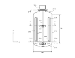
- FIG. 100 Details of an example of the polymerization apparatus 100 will be described with reference to FIGS. 1, 2, 3 and 4.
- FIG. The polymerization apparatus 100 is used, for example, for production of polymers.
- the polymerization apparatus 100 may be used for suspension polymerization applications.
- the suspension of vinyl chloride monomers or monomer mixtures mainly composed of vinyl chloride compounds (both together are sometimes referred to as vinyl chloride monomers).
- the required power of the stirrer 120 increases.
- the shape, size and installation position of the internal structure described above affect the mixing performance of the polymerization apparatus 100 . Therefore, depending on the internal structure, a portion of slow flow may occur inside the reaction vessel 110 . When a portion of slow flow occurs inside the reaction vessel 110, the temperature inside the reaction vessel 110 becomes non-uniform.
- the content of the reaction vessel 110 is not particularly limited, the content of the reaction vessel 110 is, for example, 1 to 300 m 3 .
- the lower limit of the content of the reaction vessel 110 may be 40 m3 , 80 m3 , 100 m3 , 120 m3 , or 130 m3 . , may be 150 m3 , may be 200 m3 , or may be 250 m3 .
- the upper limit of the content of the reaction vessel 110 may be 300 m 3 or more.
- the upper limit of the content of the reaction vessel 110 may be 350 m 3 or 400 m 3 . The greater the internal capacity of the reaction vessel 110, the more advantageous the improvement in the cooling capacity according to the present embodiment.
- the internal capacity of the reaction container 110 is determined as the capacity when the liquid is stored in the reaction container 110 up to a predetermined upper limit position of the reaction container 110 .
- the internal volume of the reaction vessel 110 is, for example, the internal volume of the reaction vessel 110 when internal structures such as a stirring shaft, blades, baffles, and coils are not disposed inside the reaction vessel 110 .
- the number of rotations of the stirring shaft 122, the shape, size, number of blades, installation position, number of installations, and installation interval Pi of the stirring blades 124 are appropriately determined according to the application of the polymerization apparatus 100.
- the number of rotations of the stirring shaft 122, the shape, size, number of blades, installation position, number of installations, and installation interval Pi of the stirring blades 124 are, for example, determined by the content of the reaction vessel 110, the shape of the reaction vessel 110, and the reaction vessel. It is determined in consideration of the internal structure arranged inside 110, the configuration of the heat removal means, the heat removal capacity, and the composition of the raw material charged for polymerization.
- the stirring energy applied to the contents is 80 to 200 kgf ⁇ m/s ⁇ m 3 .
- the rotation speed of the stirring shaft 122 is determined.
- the "stirring energy" applied to the contents is calculated from the energy A applied to the stirrer driving motor arranged in the power mechanism 126 during the operation of the polymerization apparatus 100, the motor efficiency, the conduction loss, and the mechanical loss. It is defined as the net energy required for stirring per unit amount of contents (sometimes referred to as unit content) after subtracting various energy losses B such as.
- unit content the stirring energy is calculated by the following formula (1).
- the rotation speed of the stirring shaft 122 in the polymerization device 100 can be determined so that the stirring energy in the polymerization device 100 and the stirring energy in the pilot plant are substantially the same.
- the stirring energy is calculated as "(AB)/C", for example. Any known method can be adopted as a method for determining the rotation speed of the stirring shaft 122 based on the stirring energy.
- the number and arrangement of the baffles 130 in the intended polymerization apparatus 100 are determined so that the number and arrangement of the baffles 130 are substantially the same between the pilot plant and the intended polymerization apparatus 100 .
- the above ratio exceeds 3%, the required power of the stirrer 120 increases excessively. Also, fluidity between the baffle 130 and the inner wall surface of the reaction vessel 110 may be reduced. As a result, scale may easily adhere to the reaction vessel 110 or structures inside the reaction vessel 110 . For example, if the polymerization apparatus 100 includes more than eight baffles 130, the percentage may exceed 3% depending on the design of the polymerization apparatus 100.
- the main body 132 is connected to the inner wall surface of the reaction container 110 via a support 134, for example.
- the distance between the main body 132 and the inner wall surface of the polymerization apparatus 100 is preferably 40 mm or more. If the distance is less than 40 mm, polymer scale may easily adhere between the inner wall surface of the reaction vessel 110 and the baffle 130 near the gas-liquid interface inside the reaction vessel 110 . Details of the main body 132 will be described later.
- the heat medium may be a known refrigerant.
- refrigerants include water, brine, freon, and other liquefied gases. If a liquefied gas is used as the coolant, the liquefied gas may function as a coolant by evaporating inside the serpentine cooling tube 140 .
- the linear velocity of the refrigerant may be about 0.1 to 6.0 m/s.
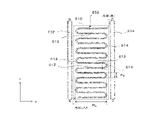
- the meandering cooling pipe 150 extends while repeatedly bending.
- the length Ph in the extending direction of the portion of the meandering cooling pipe 150 that extends while repeatedly bending may be smaller than the length Bh in the extending direction (the z-direction in the drawing) of the main body 132 of the baffle 130 . , may be substantially the same as the Bh, or may be larger than the Bh. This increases the heat transfer area per installation area.
- polymerization apparatus 100 is used for the production of polymers.
- the polymerization method may be suspension polymerization or emulsion polymerization. More specifically, the polymerization apparatus 100 can handle various vinyl-based monomers, for example, olefins such as ethylene and propylene, vinyl halides such as vinyl chloride and vinylidene chloride, vinyl esters such as vinyl acetate, ethyl Vinyl ethers such as vinyl ethers, (meth)acrylic acid esters such as methyl methacrylate, metal salts or esters of maleic acid or fumaric acid, aromatic vinyls such as styrene, diene monomers such as butadiene, chloroprene, and isoprene It is used for the production of polymers by polymerizing polyethers, acrylonitrile, etc.
- the polymerization apparatus 100 is particularly suitably used for production of a polymer by polymerizing vinyl chloride or a monomer mixture
- various polymerization conditions may be the same as known polymerization conditions.
- Examples of the above-described polymerization conditions include the charging ratio of the raw materials, the charging method of the raw materials, the polymerization temperature, and the like.
- polymerization modifiers chain transfer agents, pH modifiers, buffers, gelation modifiers, antistatic agents, scale inhibitors, etc., which are appropriately used for the polymerization of vinyl chloride, can be added.
- the reduced viscosity (K value) of the vinyl chloride polymer obtained in the present invention the polymer can be obtained in a desired range by using the apparatus of the present invention. A range of polymers can be obtained.
- pH adjusters or buffers include citric acid, trisodium citrate, diammonium citrate, triammonium citrate, potassium hydrogen phthalate, sodium nitrate, sodium carbonate, potassium carbonate, cesium carbonate, sodium hydrogen carbonate, hydroxide Examples include sodium, potassium hydroxide, barium hydroxide, disodium phosphate, dipotassium phosphate, and tripotassium phosphate.
- the above pH adjusters or buffers may be used alone, or two or more of them may be used in combination.
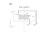
- the refrigerant supplied from the refrigerant supply pipe 332 to the reaction vessel 110 flows into the baffle 232, passes through the baffles 234, 236 and 238, and is discharged to the refrigerant return pipe 334.
- the refrigerant distribution method is not limited to this embodiment.
- baffle 232 refrigerant supplied to the reaction vessel 110 from the refrigerant supply pipe 332 flows into the baffle 232, passes through the baffle 234, and is discharged to the refrigerant return pipe 334.
- the coolant supplied from the coolant supply pipe 332 to the reaction vessel 110 flows into the baffle 238 , passes through the baffle 236 , and is discharged to the coolant return pipe 334 .
- each of baffle 232, baffle 234, baffle 236, and baffle 238 are configured to independently control the flow rate of refrigerant supplied to each baffle.
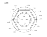
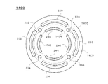
- FIG. 4 shows a schematic plan view of an example of the reaction vessel 110.
- baffle 232, baffle 234, baffle 236 and baffle 238, (ii) serpentine cooling tube 242, serpentine cooling tube 244, serpentine cooling tube 246 and serpentine cooling tube 248, and (iii) serpentine cooling Tube 252, serpentine cooling tube 254, serpentine cooling tube 256 and serpentine cooling tube 258 are arranged concentrically.
- the meandering cooling pipe 242, the meandering cooling pipe 244, the meandering cooling pipe 246, and the meandering cooling pipe 248 are arranged on substantially the same circumference. Further, in the present embodiment, (i) baffle 232, baffle 234, baffle 236, and baffle 238, and (ii) meandering cooling pipe 252, meandering cooling pipe 254, meandering cooling pipe 256, and meandering cooling pipe 258 are substantially circular. distributed around the circumference.
- L1 may be set so that the distance between the outer circumference of each meandering cooling pipe and the inner surface of the straight body portion 312 is 40 mm or more. preferable. Note that L1 may be set to 40 mm or more. If the distance or L1 is less than 40 mm, polymer scale may easily adhere between the inner wall surface of the reaction vessel 110 and the meandering cooling pipe 150 near the gas-liquid interface inside the reaction vessel 110. be.
- the distance Pc between the meandering cooling pipe 242 and the meandering cooling pipe 252 is preferably 40 mm or more.
- the distance Pc is determined, for example, by calculating the minimum value of the distance between the outer circumference of the meandering cooling pipe 242 and the outer circumference of the meandering cooling pipe 252 in the cross section. When Pc is less than 40 mm, polymer scale may easily adhere.
- the polymerization apparatus 100 has been described, taking as an example the case where the meandering cooling pipes are doubled from the center of the straight body portion 312 toward the outside.
- the polymerization device 100 is not limited to this embodiment.
- three or more meandering cooling pipes may be multiplexed outward from the center of the straight body portion 312 . It is preferable that the meandering cooling pipes are multiplexed two to five times from the center of the straight body portion 312 toward the outside.
- the piping may be configured so that the refrigerant that has flowed in from below the baffle 232 flows out from above the baffle 232 and flows into the baffle 234 from above.
- baffle 232 may be a single tube.
- the PL of more than 1/2 of the plurality of extending portions 612 may be smaller than 2/3 of the length of the inner circumference of the straight body portion 312 .
- the above PL may be 1/2 or less of the length of the inner circumference of the straight body portion 312, or may be smaller than 1/2 of the length of the inner circumference of the straight body portion 312. may be 1/3 or less of the length of the inner circumference of the straight body portion 312, or less than 1/3 of the length of the inner circumference of the straight body portion 312, or 1/3 of the length of the inner circumference of the straight body portion 312.
- the polymerization apparatus 1300 has been described with the baffle 1331, the baffle 1332, the baffle 1333, the baffle 1334, the baffle 1335, and the baffle 1336 arranged at the vertices of a virtual regular hexagon.
- the polymerization device 1300 is not limited to this embodiment.
- the meandering cooling pipes 140 and the meandering cooling pipes 150 are arranged in multiple stages in the radial direction of the straight body portion 312, the meandering cooling pipes 140 and the meandering cooling pipes 140 and 150 Slurry can accumulate in the areas between the cooling pipes 150 .
- Suspension polymerization of vinyl chloride is exemplified as a case where the viscosity of the slurry is relatively high. Even in such a case, the number of radial stages of the meandering cooling pipes 140 and the meandering cooling pipes 150 changes along the circumferential direction of the straight body portion 312, thereby suppressing slurry retention. As a result, mixing of the slurry is promoted.
- each of the four meandering cooling pipes 140 made of austenitic stainless steel cylindrical pipes with an outer diameter of 90 mm were arranged inside the reaction vessel 110.
- the distance between the center of each of the four meandering cooling pipes 140 and the central axis of the reaction vessel 110 was 1360 mm.
- the four meandering cooling pipes 140 were arranged at symmetrical positions about the central axis of the reaction vessel 110 .
- Each of the four meandering cooling pipes 140 had 12 stages.
- each of the four serpentine cooling tubes 140 had twelve extensions 612 .
- the distance between adjacent extensions 612 (sometimes referred to as pitch Pp) was 400 mm.
- each of the four meandering cooling pipes 150 made of austenitic stainless steel cylindrical pipes with an outer diameter of 90 mm were installed inside the reaction vessel 110.
- the distance between the center of each of the four meandering cooling pipes 150 and the central axis of the reaction vessel 110 was 1610 mm.
- the four meandering cooling pipes 150 were arranged at symmetrical positions about the central axis of the reaction vessel 110 .
- Each of the four meandering cooling pipes 150 had 12 stages.
- the pitch Pp was 400 mm for each of the four meandering cooling pipes 150 .
- the ratio of the total surface area of the meandering cooling pipe 140 and the meandering cooling pipe 150 to the content of the reaction vessel 110 was 0.645 [m 2 /m 3 ].
- the rotational speed of the stirring shaft 122 was determined in consideration of experimental results obtained using a pilot plant.
- the number of revolutions of the stirring shaft 122 was determined so that the above-described stirring energy was 80 to 200 kgf ⁇ m/s ⁇ m 3 in consideration of the results of pilot plant experiments.
- the rotational speed of the stirring shaft 122 was determined so that the target quality was obtained at the polymerization temperature at which the K value of the produced vinyl chloride resin was 65.1.
- the reduced viscosity (K value) of vinyl chloride resin was measured according to JIS K 7367-2.
- the shape and number of stirring blades 124, and the installation position, installation quantity, and installation interval Pi of the stirring blades 124 were scaled up in the same manner as the stirring blades 124 used in the pilot plant.
- the size of the stirring blade 124 was scaled up so that the ratio of the size of the stirring blade 124 to the size of the reaction vessel 110 used in the pilot plant was constant.
- baffle 232, baffle 234, baffle 236 and baffle 238 were determined.
- an isoparaffin solution containing di-2-ethylhexylperoxydicarbonate was used as the polymerization initiator A. The amount of di-2-ethylhexylperoxydicarbonate added was 34.4 kg.
- an isoparaffin solution containing t-butyl peroxyneodecanate was used as the polymerization initiator B. The amount of t-butyl peroxyneodecanate added was 3.3 kg.
- an isoparaffin solution containing cumyl peroxyneodecanate was used as the polymerization initiator C. The amount of cumyl peroxyneodecanate added was 7.7 kg.
- hot water was passed through the jacket 170 to raise the temperature of the mixed solution inside the reaction vessel 110 to 57°C, thereby initiating polymerization. Further, when the temperature of the mixed solution inside the reaction vessel 110 reached 57° C., cooling water was started to flow through the baffle 130 , the meandering cooling pipe 140 , the meandering cooling pipe 150 and the jacket 170 . After that, when the polymerization conversion reached 20%, the reflux condenser 180 was operated.
- Example 1 the time from the addition of the polymerization initiator to the completion of the polymerization reaction was measured. Moreover, after the polymerization reaction was completed, the reduced viscosity (K value) of the synthesized vinyl chloride resin was measured. Table 4 shows the measurement results of K value and polymerization time. Also, after the polymerization test was completed a predetermined number of times, the state of adhesion of scale inside the reaction vessel 110 was visually confirmed. Table 4 shows the confirmation result of the scale adhesion state.
- Example 2-4 A vinyl chloride polymer was synthesized in the same manner as in Example 1 using the polymerization apparatus 100 having the specifications shown in Table 1. In Examples 2-4, the target K value was 65.1. Table 4 shows the details of the reaction conditions in each example. Table 4 shows the measurement results of the K value and the polymerization time, and the confirmation results of the scale adhesion state.
- Example 5-8 Using the polymerization apparatus 100 or the polymerization apparatus 1100 having the specifications shown in Table 2, a vinyl chloride polymer was synthesized in the same manner as in Example 1. In Examples 5-7, the target K value was 65.1. In Example 8, the target K value was 58.6. Table 5 shows the details of the reaction conditions in each example. Table 5 shows the measurement results of the K value and the polymerization time, and the confirmation results of the scale adhesion state.
- Example 9-10 Using the polymerization apparatus 100 or polymerization apparatus 1100 having the specifications shown in Table 3, a vinyl chloride polymer was synthesized in the same manner as in Example 1.
- the target K value was 65.1.
- Table 6 shows the details of the reaction conditions in each example. Table 6 shows the measurement results of the K value and the polymerization time, and the confirmation results of the scale adhesion state.
- Comparative example 1 A vinyl chloride polymer was synthesized in the same manner as in Example 1 using the polymerization apparatus disclosed in Patent Document 2. In Comparative Example 1, the target K value was 65.1.
- a coiled cooling pipe was used in the polymerization apparatus of Comparative Example 1.
- a cylindrical pipe made of austenitic stainless steel with an outer diameter of 60 mm was used as the cooling pipe.
- the distance between the center of the coiled cooling pipe and the center of the reaction vessel 110 was 1100 mm.
- the number of coil stages was 12, and the coil pitch was 400 mm.
- a coiled cooling pipe was used instead of the meandering cooling pipe 150.
- a cylindrical pipe made of austenitic stainless steel with an outer diameter of 60 mm was used as the cooling pipe.
- the distance between the center of the coiled cooling pipe and the center of the reaction vessel 110 was 1350 mm.
- the number of coil stages was 12, and the coil pitch was 400 mm.
- Table 6 shows the details of the reaction conditions in the comparative example.
- Table 6 shows the measurement results of the K value and the polymerization time, and the confirmation results of the scale adhesion state.
- vinyl chloride polymers with a K value of 65.1 were obtained in Examples 1 to 7 and 9 to 10. Moreover, the polymerization time was 2 to 3 hours, which was about the same as the planned value. In Example 8, a vinyl chloride polymer with a K value of 58.6 was obtained. Moreover, the polymerization time was 150 minutes, which was about the same as the planned value. In Examples 1 to 10, adhesion of scale could not be confirmed even after repeated polymerization tests. Each example shows that the polymerization equipment has sufficient cooling capacity. Further, each example shows that it is possible to simultaneously increase the size of the reaction vessel and shorten the polymerization time.
- Comparative Example 1 a vinyl chloride polymer having a K value of 65.1 was obtained. Moreover, the polymerization time was 2 hours and 10 minutes, which was about the same as the planned value. Even when the polymerization apparatus of Comparative Example 1 was used, a vinyl chloride polymer having the desired K value could be synthesized in a relatively short period of time with a volume of about 80 m 3 . However, after the polymerization test was repeatedly performed, adhesion of scale was confirmed although it was very slight.
- 100 polymerization device 110 reaction vessel, 120 stirrer, 122 stirring shaft, 124 stirring blade, 126 power mechanism, 130 baffle, 132 body, 134 support, 140 meandering cooling pipe, 150 meandering cooling pipe, 170 jacket, 172 flow path, 180 Reflux condenser, 182 flow path, 232 baffle, 234 baffle, 236 baffle, 238 baffle, 242 meandering cooling pipe, 244 meandering cooling pipe, 246 meandering cooling pipe, 248 meandering cooling pipe, 252 meandering cooling pipe, 254 meandering cooling pipe, 256 meandering cooling pipe, 258 meandering cooling pipe, 312 straight body portion, 314 first end plate, 316 second end plate, 318 pedestal, 332 refrigerant supply pipe, 334 refrigerant return pipe, 342 connecting portion, 344 connecting portion, 346 connecting portion, 510 Inner pipe, 512 inlet, 520 outer pipe, 522 outlet, 532 pipe, 534 pipe, 542 flow control valve, 544 flow control
Landscapes
- Chemical & Material Sciences (AREA)
- Chemical Kinetics & Catalysis (AREA)
- Organic Chemistry (AREA)
- Health & Medical Sciences (AREA)
- Medicinal Chemistry (AREA)
- Polymers & Plastics (AREA)
- Polymerisation Methods In General (AREA)
- Mixers Of The Rotary Stirring Type (AREA)
- Accessories For Mixers (AREA)
- Physical Or Chemical Processes And Apparatus (AREA)
Priority Applications (9)
| Application Number | Priority Date | Filing Date | Title |
|---|---|---|---|
| KR1020237034652A KR20240022448A (ko) | 2021-06-16 | 2022-06-15 | 반응 장치 및 비닐계 중합체의 제조 방법 |
| EP22825043.7A EP4357018A4 (en) | 2021-06-16 | 2022-06-15 | REACTION APPARATUS AND PROCESS FOR PRODUCING VINYL-BASED POLYMER |
| JP2023530389A JP7608605B2 (ja) | 2021-06-16 | 2022-06-15 | 反応装置、及び、ビニル系重合体の製造方法 |
| BR112023026126A BR112023026126A2 (pt) | 2021-06-16 | 2022-06-15 | Aparelho de reação e método para produzir polímero à base de vinila |
| MX2023015025A MX2023015025A (es) | 2021-06-16 | 2022-06-15 | Aparato de reaccion y metodo para producir polimero a base de vinilo. |
| CA3224346A CA3224346A1 (en) | 2021-06-16 | 2022-06-15 | Reaction apparatus and method for producing vinyl-based polymer |
| CN202280028106.5A CN117177810A (zh) | 2021-06-16 | 2022-06-15 | 反应装置及乙烯系聚合物的制造方法 |
| US18/518,613 US20240091735A1 (en) | 2021-06-16 | 2023-11-24 | Reactor apparatus, and vinyl-based polymer manufacturing method |
| JP2024186138A JP2025011319A (ja) | 2021-06-16 | 2024-10-22 | 反応装置、及び、ビニル系重合体の製造方法 |
Applications Claiming Priority (2)
| Application Number | Priority Date | Filing Date | Title |
|---|---|---|---|
| JP2021100495 | 2021-06-16 | ||
| JP2021-100495 | 2021-06-16 |
Related Child Applications (1)
| Application Number | Title | Priority Date | Filing Date |
|---|---|---|---|
| US18/518,613 Continuation US20240091735A1 (en) | 2021-06-16 | 2023-11-24 | Reactor apparatus, and vinyl-based polymer manufacturing method |
Publications (1)
| Publication Number | Publication Date |
|---|---|
| WO2022265055A1 true WO2022265055A1 (ja) | 2022-12-22 |
Family
ID=84527116
Family Applications (1)
| Application Number | Title | Priority Date | Filing Date |
|---|---|---|---|
| PCT/JP2022/024028 Ceased WO2022265055A1 (ja) | 2021-06-16 | 2022-06-15 | 反応装置、及び、ビニル系重合体の製造方法 |
Country Status (9)
| Country | Link |
|---|---|
| US (1) | US20240091735A1 (https=) |
| EP (1) | EP4357018A4 (https=) |
| JP (2) | JP7608605B2 (https=) |
| KR (1) | KR20240022448A (https=) |
| CN (1) | CN117177810A (https=) |
| BR (1) | BR112023026126A2 (https=) |
| CA (1) | CA3224346A1 (https=) |
| MX (1) | MX2023015025A (https=) |
| WO (1) | WO2022265055A1 (https=) |
Families Citing this family (1)
| Publication number | Priority date | Publication date | Assignee | Title |
|---|---|---|---|---|
| KR102719973B1 (ko) * | 2024-05-23 | 2024-10-23 | 주식회사 한울엔지니어링 | 분쇄, 혼합 및 열처리가 가능한 일체형 분체 제조장치 |
Citations (10)
| Publication number | Priority date | Publication date | Assignee | Title |
|---|---|---|---|---|
| JPS62244429A (ja) * | 1986-04-16 | 1987-10-24 | Dai Ichi Kogyo Seiyaku Co Ltd | 撹拌装置 |
| JPH055008A (ja) * | 1991-03-05 | 1993-01-14 | Nippon Zeon Co Ltd | 塩化ビニル系単量体の重合方法 |
| JPH07233206A (ja) * | 1993-12-27 | 1995-09-05 | Shin Etsu Chem Co Ltd | 重合装置及びそれを用いる塩化ビニル系重合体の製造方法 |
| JPH07233202A (ja) * | 1993-12-27 | 1995-09-05 | Shin Etsu Chem Co Ltd | 重合装置及びそれを用いる塩化ビニル系重合体の製造方法 |
| JPH08134107A (ja) * | 1994-09-14 | 1996-05-28 | Shin Etsu Chem Co Ltd | 塩化ビニル系重合体の製造方法 |
| JP2002128810A (ja) * | 2000-10-30 | 2002-05-09 | Shin Etsu Chem Co Ltd | 重合装置及びこれを用いた塩化ビニル系重合体の製造方法 |
| JP2006111661A (ja) * | 2004-10-12 | 2006-04-27 | Kaneka Corp | リフラックスコンデンサー付設重合器並びにその重合器を用いた重合体の製造方法 |
| JP2013151621A (ja) | 2012-01-26 | 2013-08-08 | Hitachi Chemical Co Ltd | 樹脂合成装置及び樹脂の合成方法 |
| JP2020044466A (ja) * | 2018-09-14 | 2020-03-26 | 住友金属鉱山株式会社 | 反応装置及び粒子の製造方法 |
| JP2020081955A (ja) * | 2018-11-22 | 2020-06-04 | 住友金属鉱山株式会社 | 撹拌装置 |
Family Cites Families (3)
| Publication number | Priority date | Publication date | Assignee | Title |
|---|---|---|---|---|
| ES2123090T3 (es) * | 1993-12-27 | 1999-01-01 | Shinetsu Chemical Co | Aparato de polimerizacion y procedimiento para producir un polimero de tipo cloruro de vinilo con tal aparato. |
| US5610245A (en) * | 1993-12-27 | 1997-03-11 | Shin-Etsu Chemical Co., Ltd. | Polymerization method producing vinyl chloride polymer |
| US9534196B2 (en) * | 2009-03-25 | 2017-01-03 | Ge Healthcare Bio-Sciences Corp. | Temperature controlled support surfaces for single use flexible wall systems |
-
2022
- 2022-06-15 CA CA3224346A patent/CA3224346A1/en active Pending
- 2022-06-15 KR KR1020237034652A patent/KR20240022448A/ko active Pending
- 2022-06-15 JP JP2023530389A patent/JP7608605B2/ja active Active
- 2022-06-15 EP EP22825043.7A patent/EP4357018A4/en active Pending
- 2022-06-15 MX MX2023015025A patent/MX2023015025A/es unknown
- 2022-06-15 CN CN202280028106.5A patent/CN117177810A/zh active Pending
- 2022-06-15 BR BR112023026126A patent/BR112023026126A2/pt unknown
- 2022-06-15 WO PCT/JP2022/024028 patent/WO2022265055A1/ja not_active Ceased
-
2023
- 2023-11-24 US US18/518,613 patent/US20240091735A1/en active Pending
-
2024
- 2024-10-22 JP JP2024186138A patent/JP2025011319A/ja not_active Withdrawn
Patent Citations (10)
| Publication number | Priority date | Publication date | Assignee | Title |
|---|---|---|---|---|
| JPS62244429A (ja) * | 1986-04-16 | 1987-10-24 | Dai Ichi Kogyo Seiyaku Co Ltd | 撹拌装置 |
| JPH055008A (ja) * | 1991-03-05 | 1993-01-14 | Nippon Zeon Co Ltd | 塩化ビニル系単量体の重合方法 |
| JPH07233206A (ja) * | 1993-12-27 | 1995-09-05 | Shin Etsu Chem Co Ltd | 重合装置及びそれを用いる塩化ビニル系重合体の製造方法 |
| JPH07233202A (ja) * | 1993-12-27 | 1995-09-05 | Shin Etsu Chem Co Ltd | 重合装置及びそれを用いる塩化ビニル系重合体の製造方法 |
| JPH08134107A (ja) * | 1994-09-14 | 1996-05-28 | Shin Etsu Chem Co Ltd | 塩化ビニル系重合体の製造方法 |
| JP2002128810A (ja) * | 2000-10-30 | 2002-05-09 | Shin Etsu Chem Co Ltd | 重合装置及びこれを用いた塩化ビニル系重合体の製造方法 |
| JP2006111661A (ja) * | 2004-10-12 | 2006-04-27 | Kaneka Corp | リフラックスコンデンサー付設重合器並びにその重合器を用いた重合体の製造方法 |
| JP2013151621A (ja) | 2012-01-26 | 2013-08-08 | Hitachi Chemical Co Ltd | 樹脂合成装置及び樹脂の合成方法 |
| JP2020044466A (ja) * | 2018-09-14 | 2020-03-26 | 住友金属鉱山株式会社 | 反応装置及び粒子の製造方法 |
| JP2020081955A (ja) * | 2018-11-22 | 2020-06-04 | 住友金属鉱山株式会社 | 撹拌装置 |
Non-Patent Citations (1)
| Title |
|---|
| See also references of EP4357018A4 |
Also Published As
| Publication number | Publication date |
|---|---|
| BR112023026126A2 (pt) | 2024-03-05 |
| CN117177810A (zh) | 2023-12-05 |
| EP4357018A1 (en) | 2024-04-24 |
| JP7608605B2 (ja) | 2025-01-06 |
| JPWO2022265055A1 (https=) | 2022-12-22 |
| EP4357018A4 (en) | 2025-06-18 |
| US20240091735A1 (en) | 2024-03-21 |
| JP2025011319A (ja) | 2025-01-23 |
| MX2023015025A (es) | 2024-02-16 |
| CA3224346A1 (en) | 2022-12-22 |
| KR20240022448A (ko) | 2024-02-20 |
Similar Documents
| Publication | Publication Date | Title |
|---|---|---|
| JP2025087810A (ja) | 反応装置、ビニル系重合体の製造方法、制御装置、及び、攪拌装置 | |
| JPH06199912A (ja) | 塩化ビニル系重合体の製造方法 | |
| JP2025011319A (ja) | 反応装置、及び、ビニル系重合体の製造方法 | |
| EP0664156B1 (en) | Polymerization apparatus and method of producing vinyl chloride type polymer by using the same | |
| CN117136200A (zh) | 反应装置、乙烯系聚合物的制造方法、控制装置及搅拌装置 | |
| JP3197447B2 (ja) | 重合装置及びそれを用いる塩化ビニル系重合体の製造方法 | |
| EP0701863B1 (en) | Polymerization apparatus and a method for producing polymer using the same | |
| US5610245A (en) | Polymerization method producing vinyl chloride polymer | |
| JP3197445B2 (ja) | 重合装置及びそれを用いる塩化ビニル系重合体の製造方法 | |
| US5462998A (en) | Vinyl chloride polymerization process using ball valves in recycle line | |
| JP3129154B2 (ja) | 塩化ビニル系重合体の製造方法 | |
| US5444131A (en) | Polymerization process with recycle line containing screen with rodlike projection | |
| US11078316B2 (en) | Method for polymerization with external cooling | |
| JP2007260646A (ja) | 反応器ならびにその反応器を用いた重合体の製造方法 | |
| US5348708A (en) | Polymerizing apparatus | |
| JP3388662B2 (ja) | 重合装置及びこれを用いた重合停止方法 | |
| JPH04154806A (ja) | 塩化ビニル系単量体の懸濁重合方法 | |
| JP2001247603A (ja) | 塩化ビニル系重合体の製造方法 |
Legal Events
| Date | Code | Title | Description |
|---|---|---|---|
| 121 | Ep: the epo has been informed by wipo that ep was designated in this application |
Ref document number: 22825043 Country of ref document: EP Kind code of ref document: A1 |
|
| WWE | Wipo information: entry into national phase |
Ref document number: 2023530389 Country of ref document: JP |
|
| WWE | Wipo information: entry into national phase |
Ref document number: MX/A/2023/015025 Country of ref document: MX |
|
| WWE | Wipo information: entry into national phase |
Ref document number: 202317085414 Country of ref document: IN |
|
| WWE | Wipo information: entry into national phase |
Ref document number: 3224346 Country of ref document: CA |
|
| REG | Reference to national code |
Ref country code: BR Ref legal event code: B01A Ref document number: 112023026126 Country of ref document: BR |
|
| WWE | Wipo information: entry into national phase |
Ref document number: 2022825043 Country of ref document: EP |
|
| NENP | Non-entry into the national phase |
Ref country code: DE |
|
| ENP | Entry into the national phase |
Ref document number: 2022825043 Country of ref document: EP Effective date: 20240116 |
|
| ENP | Entry into the national phase |
Ref document number: 112023026126 Country of ref document: BR Kind code of ref document: A2 Effective date: 20231212 |