WO2022264483A1 - 絞り弁制御装置 - Google Patents
絞り弁制御装置 Download PDFInfo
- Publication number
- WO2022264483A1 WO2022264483A1 PCT/JP2022/003961 JP2022003961W WO2022264483A1 WO 2022264483 A1 WO2022264483 A1 WO 2022264483A1 JP 2022003961 W JP2022003961 W JP 2022003961W WO 2022264483 A1 WO2022264483 A1 WO 2022264483A1
- Authority
- WO
- WIPO (PCT)
- Prior art keywords
- throttle
- bearing
- throttle valve
- motor
- control device
- Prior art date
- Legal status (The legal status is an assumption and is not a legal conclusion. Google has not performed a legal analysis and makes no representation as to the accuracy of the status listed.)
- Ceased
Links
Images


Classifications
-
- F—MECHANICAL ENGINEERING; LIGHTING; HEATING; WEAPONS; BLASTING
- F02—COMBUSTION ENGINES; HOT-GAS OR COMBUSTION-PRODUCT ENGINE PLANTS
- F02D—CONTROLLING COMBUSTION ENGINES
- F02D9/00—Controlling engines by throttling air or fuel-and-air induction conduits or exhaust conduits
- F02D9/08—Throttle valves specially adapted therefor; Arrangements of such valves in conduits
- F02D9/10—Throttle valves specially adapted therefor; Arrangements of such valves in conduits having pivotally-mounted flaps
- F02D9/1065—Mechanical control linkage between an actuator and the flap, e.g. including levers, gears, springs, clutches, limit stops of the like
-
- F—MECHANICAL ENGINEERING; LIGHTING; HEATING; WEAPONS; BLASTING
- F02—COMBUSTION ENGINES; HOT-GAS OR COMBUSTION-PRODUCT ENGINE PLANTS
- F02D—CONTROLLING COMBUSTION ENGINES
- F02D11/00—Arrangements for, or adaptations to, non-automatic engine control initiation means, e.g. operator initiated
- F02D11/06—Arrangements for, or adaptations to, non-automatic engine control initiation means, e.g. operator initiated characterised by non-mechanical control linkages, e.g. fluid control linkages or by control linkages with power drive or assistance
- F02D11/10—Arrangements for, or adaptations to, non-automatic engine control initiation means, e.g. operator initiated characterised by non-mechanical control linkages, e.g. fluid control linkages or by control linkages with power drive or assistance of the electric type
-
- F—MECHANICAL ENGINEERING; LIGHTING; HEATING; WEAPONS; BLASTING
- F02—COMBUSTION ENGINES; HOT-GAS OR COMBUSTION-PRODUCT ENGINE PLANTS
- F02D—CONTROLLING COMBUSTION ENGINES
- F02D9/00—Controlling engines by throttling air or fuel-and-air induction conduits or exhaust conduits
- F02D9/08—Throttle valves specially adapted therefor; Arrangements of such valves in conduits
- F02D9/10—Throttle valves specially adapted therefor; Arrangements of such valves in conduits having pivotally-mounted flaps
- F02D9/1035—Details of the valve housing
-
- F—MECHANICAL ENGINEERING; LIGHTING; HEATING; WEAPONS; BLASTING
- F02—COMBUSTION ENGINES; HOT-GAS OR COMBUSTION-PRODUCT ENGINE PLANTS
- F02M—SUPPLYING COMBUSTION ENGINES IN GENERAL WITH COMBUSTIBLE MIXTURES OR CONSTITUENTS THEREOF
- F02M26/00—Engine-pertinent apparatus for adding exhaust gases to combustion-air, main fuel or fuel-air mixture, e.g. by exhaust gas recirculation [EGR] systems
- F02M26/65—Constructional details of EGR valves
- F02M26/72—Housings
- F02M26/73—Housings with means for heating or cooling the EGR valve
-
- F—MECHANICAL ENGINEERING; LIGHTING; HEATING; WEAPONS; BLASTING
- F02—COMBUSTION ENGINES; HOT-GAS OR COMBUSTION-PRODUCT ENGINE PLANTS
- F02D—CONTROLLING COMBUSTION ENGINES
- F02D11/00—Arrangements for, or adaptations to, non-automatic engine control initiation means, e.g. operator initiated
- F02D11/06—Arrangements for, or adaptations to, non-automatic engine control initiation means, e.g. operator initiated characterised by non-mechanical control linkages, e.g. fluid control linkages or by control linkages with power drive or assistance
- F02D11/10—Arrangements for, or adaptations to, non-automatic engine control initiation means, e.g. operator initiated characterised by non-mechanical control linkages, e.g. fluid control linkages or by control linkages with power drive or assistance of the electric type
- F02D2011/101—Arrangements for, or adaptations to, non-automatic engine control initiation means, e.g. operator initiated characterised by non-mechanical control linkages, e.g. fluid control linkages or by control linkages with power drive or assistance of the electric type characterised by the means for actuating the throttles
-
- F—MECHANICAL ENGINEERING; LIGHTING; HEATING; WEAPONS; BLASTING
- F02—COMBUSTION ENGINES; HOT-GAS OR COMBUSTION-PRODUCT ENGINE PLANTS
- F02D—CONTROLLING COMBUSTION ENGINES
- F02D11/00—Arrangements for, or adaptations to, non-automatic engine control initiation means, e.g. operator initiated
- F02D11/06—Arrangements for, or adaptations to, non-automatic engine control initiation means, e.g. operator initiated characterised by non-mechanical control linkages, e.g. fluid control linkages or by control linkages with power drive or assistance
- F02D11/10—Arrangements for, or adaptations to, non-automatic engine control initiation means, e.g. operator initiated characterised by non-mechanical control linkages, e.g. fluid control linkages or by control linkages with power drive or assistance of the electric type
- F02D2011/108—Arrangements for, or adaptations to, non-automatic engine control initiation means, e.g. operator initiated characterised by non-mechanical control linkages, e.g. fluid control linkages or by control linkages with power drive or assistance of the electric type with means for detecting or resolving a stuck throttle, e.g. when being frozen in a position
-
- F—MECHANICAL ENGINEERING; LIGHTING; HEATING; WEAPONS; BLASTING
- F02—COMBUSTION ENGINES; HOT-GAS OR COMBUSTION-PRODUCT ENGINE PLANTS
- F02D—CONTROLLING COMBUSTION ENGINES
- F02D41/00—Electrical control of supply of combustible mixture or its constituents
- F02D41/24—Electrical control of supply of combustible mixture or its constituents characterised by the use of digital means
- F02D41/2406—Electrical control of supply of combustible mixture or its constituents characterised by the use of digital means using essentially read only memories
- F02D41/2425—Particular ways of programming the data
- F02D41/2429—Methods of calibrating or learning
-
- F—MECHANICAL ENGINEERING; LIGHTING; HEATING; WEAPONS; BLASTING
- F02—COMBUSTION ENGINES; HOT-GAS OR COMBUSTION-PRODUCT ENGINE PLANTS
- F02D—CONTROLLING COMBUSTION ENGINES
- F02D9/00—Controlling engines by throttling air or fuel-and-air induction conduits or exhaust conduits
- F02D9/08—Throttle valves specially adapted therefor; Arrangements of such valves in conduits
- F02D9/10—Throttle valves specially adapted therefor; Arrangements of such valves in conduits having pivotally-mounted flaps
- F02D9/1075—Materials, e.g. composites
- F02D9/108—Plastics
-
- Y—GENERAL TAGGING OF NEW TECHNOLOGICAL DEVELOPMENTS; GENERAL TAGGING OF CROSS-SECTIONAL TECHNOLOGIES SPANNING OVER SEVERAL SECTIONS OF THE IPC; TECHNICAL SUBJECTS COVERED BY FORMER USPC CROSS-REFERENCE ART COLLECTIONS [XRACs] AND DIGESTS
- Y02—TECHNOLOGIES OR APPLICATIONS FOR MITIGATION OR ADAPTATION AGAINST CLIMATE CHANGE
- Y02T—CLIMATE CHANGE MITIGATION TECHNOLOGIES RELATED TO TRANSPORTATION
- Y02T10/00—Road transport of goods or passengers
- Y02T10/10—Internal combustion engine [ICE] based vehicles
- Y02T10/12—Improving ICE efficiencies
Definitions
- the present invention relates to a throttle valve control device that regulates the flow rate of fluid in an internal combustion engine.
- the throttle valve control device is attached to the intake passage of the internal combustion engine, and by variably controlling the passage cross-sectional area of the intake passage, in gasoline engine vehicles, the amount of air taken into the cylinder can be adjusted, and in diesel engines, is used to control the pressure in the intake manifold.
- Gasoline engine vehicles are used in both a so-called in-cylinder direct fuel injection type engine that directly injects fuel into a cylinder and a so-called port injection type engine that injects fuel into an intake pipe.
- intake air is pressurized by the turbocharger, which increases the intake air temperature.
- the present invention provides a throttle body having an intake passage through which intake air flows, a throttle valve for adjusting the amount of air passing through the intake passage, and a throttle shaft fixed to the throttle valve.
- a throttle valve control device comprising a first bearing and a second bearing that rotatably support the throttle shaft, and a flow path through which a heat exchange medium flows is formed in the throttle body, wherein the diameter of the first bearing is:
- the flow path is larger than the diameter of the second bearing, and is arranged along the outer circumference of the intake passage so as to overlap the second bearing when viewed from the flow direction of the intake passage. It is assumed that the outlet portion is arranged so as to sandwich the first bearing.
- the flow path through which the heat exchange medium flows is arranged along the outer periphery of the intake passage so as to overlap the second bearing when viewed from the flow direction of the intake passage.
- the outer circumference of the passage can be uniformly cooled, and the second bearing can be effectively cooled.
- the inlet and outlet of the flow path are arranged so as to sandwich the first bearing, the first bearing can be effectively cooled.
- the flow path is arranged so as not to overlap with the first bearing having a large diameter, it is possible to prevent the dimension of the intake passage of the throttle body in the flow direction from increasing.
- the throttle valve control device of the present invention it is possible to effectively cool the bearing of the throttle shaft while preventing the throttle body from becoming large.
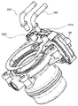
- FIG. 1 is an exploded perspective view of a motor-driven throttle valve control device used in a gasoline engine vehicle;
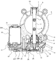
- FIG. 1 is a cross-sectional view of a motor-driven throttle valve control device used in a gasoline engine vehicle;
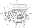
- FIG. 1 is a plan view with a plate removed of a motor-driven throttle valve control device used in a gasoline engine vehicle;
- FIG. 3 is a cross-sectional view of a cooling water passage surrounded by a dotted line in FIG. 2;
- FIG. 4 is a partially exploded perspective view of a cooling water pipe joint;
- 1 is a plan view of a motor-driven throttle valve control device used in a gasoline engine vehicle with a gear cover removed;
- FIG. 1 is an external perspective view of a motor-driven throttle valve control device used in a gasoline engine vehicle;
- FIG. 1 is a cross-sectional view of a motor-driven throttle valve control device used in a gasoline engine vehicle;
- FIG. 1 is a plan view of a motor-driven throttle valve control device used in a gasoline engine vehicle;
- FIG. 1 is an exploded perspective view of a motor-driven throttle valve control device used in a gasoline engine vehicle;
- FIG. 1 A throttle valve control device according to a first embodiment of the present invention will be described with reference to FIGS. 1 to 8.
- FIG. 1 the present invention is applied to a motor-driven throttle valve control device used in a gasoline engine vehicle.
- the throttle body 5 forms a bore 1.
- a bore 1 is an intake passage through which intake air flows.
- grooves 5T1 to 5T3 are arranged in the throttle body 5 so as to surround the outer circumference of the bore 1.
- a cooling water passage (channel) is formed by the grooves 5T1 to 5T3 and the plate 30 (see FIGS. 1 and 2).
- an inlet-side cooling water pipe 29A and an outlet-side cooling water pipe 29B which are fixed to the throttle body 5 by press fitting, are connected to the cooling water passage.
- the inlet-side cooling water pipe 29A and the outlet-side cooling water pipe 29B are interfaces with mating hoses.
- FIG. 4 is a cross-sectional view of the cooling water passage surrounded by the dotted line A in FIG.
- plate mounting portions 5F1 and 5F2 having widths larger than the width of the grooves are provided.
- the plate attachment portions 5F1 and 5F2 serve as pedestals when the plate 30 is attached. After being placed on this pedestal, the plate 30 is joined to the throttle body 5 by, for example, friction stir welding (FSW) to ensure airtightness of the cooling water passage.
- FSW friction stir welding
- a wall portion 5W is arranged between the inlet-side cooling water pipe 29A and the outlet-side cooling water pipe 29B.
- the wall portion 5W prevents the cooling water from flowing directly from the inlet side cooling water pipe 29A to the outlet side cooling water pipe 29B without passing through the vicinity of the shaft hole.
- an inlet portion 5T1 and an outlet portion 5T3 of the cooling water passage are arranged in the vicinity of the bearing 8 so as to sandwich the bearing 8 therebetween.
- a mounting hole 5H1 (body fixing portion) through which a bolt for mounting the throttle body 5 to the intake manifold passes is arranged between the inlet portion 5T1 of the cooling water passage and the motor 20 .
- the number of mounting holes may be three. At this time, it is necessary to provide a mounting hole between the inlet portion 5T1 of the cooling water passage and the motor 20 in order to ensure the vibration resistance of the throttle body.
- a throttle valve control device having excellent heat resistance can be configured with
- an aluminum die-cast throttle valve assembly (hereinafter referred to as a throttle body) 5 includes an intake passage (hereinafter referred to as a bore) 1 and a motor housing 20A for housing a motor 20. molded.
- a metal rotating shaft (hereinafter referred to as throttle shaft) 3 is arranged along one diameter line of the bore 1 in the throttle body 5 . Both ends of the throttle shaft 3 are rotatably supported by ball bearings and needle bearings as bearings 8 and 9 .
- the bearings 8 and 9 are press-fitted and fixed to bearing bosses 6 and 7 provided on the throttle body 5, respectively.
- the bearing 8 is press-fitted into the throttle body 5 after being press-fitted into the throttle shaft 3 . After that, it is press-fitted into the throttle body 5 and fixed, thereby restricting the amount of movement of the throttle shaft 3 in the axial direction. At this time, crimping may be used to fix the bearing 8 .
- the throttle shaft 3 is thus rotatably supported with respect to the throttle body 5 .
- a throttle valve (hereinafter referred to as a throttle valve) 2 composed of a disc made of metal material is inserted into a slit provided in the throttle shaft 3 and fixed to the throttle shaft 3 with a screw 4 .
- a throttle valve 2 rotates, resulting in a change in the cross-sectional area of the intake passage, thereby controlling the intake air flow rate to the engine.
- the motor housing 20A is formed substantially parallel to the throttle shaft 3.
- a motor 20 composed of a brush-type DC motor is inserted into the motor housing 20A, and the throttle body 5 is rotated.
- the flange portion of the bracket 20B of the motor 20 is fixed to the side wall of the motor 20 with screws 21.
- a wave washer 25 is provided at the end of the motor 20 to hold the motor 20.
- the openings of the bearing bosses 6 and 7 are sealed with bearings 8 and 9, respectively, which form a shaft seal portion and are configured to maintain airtightness.
- a cap 10 on the bearing boss 7 side prevents the end of the throttle shaft 3 and the bearing 9 from being exposed. This prevents air from leaking from the bearings 8 and 9 or grease for lubricating the bearings from leaking into the outside air or into a sensor chamber, which will be described later.
- a metal gear 22 having the smallest number of teeth is fixed to the end of the rotating shaft of the motor 20 .
- a reduction gear mechanism and a spring mechanism for rotationally driving the throttle shaft 3 are collectively arranged on the side of the throttle body on the side where the gear 22 is provided. These mechanisms are covered with a resin cover (hereinafter referred to as gear cover) 26 fixed to the side surface of the throttle body 5 .
- the throttle gear 11 is fixed to the end of the throttle shaft 3 on the gear cover 26 side.
- the throttle gear 11 is composed of a metal plate 12 and a resin gear portion 13 resin-molded on the metal plate 12 .
- a cup-shaped recess is provided in the center of the metal plate 12, and a flange for forming a gear is provided at the open end of the recess.
- a gear portion 13 made of a resin material is molded on the flange portion by resin molding.
- the metal plate 12 has a hole in the center. Thread grooves are formed around the tip of the throttle shaft 3 .
- the metal plate 12 is fixed to the throttle shaft 3 by inserting the tip of the throttle shaft 3 into the hole of the metal plate 12 and screwing the nut 17 onto the threaded portion.
- the metal plate 12 and the resin gear portion 13 formed thereon rotate integrally with the throttle shaft 3 .
- a default spring 15 made of a coiled spring is sandwiched between the back surface of the throttle gear 11 and the default lever 16 .
- a return spring 14 formed of a helical spring is sandwiched between the back surface of the default lever 16 and the side surface of the throttle body 5 .
- the initial position of the throttle valve 2 that is, the opening position given as the initial position of the throttle valve 2 when the power of the motor 20 is turned off, is Default opening. Therefore, when the throttle valve 2 is more open than the default opening, the load in the closing direction toward the default opening is applied by the return spring 14, and when the throttle valve 2 is more closed than the default opening, the default spring 15 A load acts in the opening direction toward the default opening.
- a metal gear shaft 24 press-fitted to the side surface of the throttle body 5 is rotatably supported between a gear 22 attached to the rotating shaft of the motor 20 and a throttle gear 11 fixed to the throttle shaft 3 .
- the intermediate gear 23 is meshed.
- the intermediate gear 23 is composed of a large-diameter gear 23A meshing with the gear 22 and a small-diameter gear 23B meshing with the throttle gear 11. As shown in FIG. Both gears are molded integrally by resin molding.
- These gears 22, 23A, 23B and 11 constitute a two-stage reduction gear mechanism.
- the rotation of the motor 20 is transmitted to the throttle shaft 3 via this reduction gear mechanism.
- the speed reduction mechanism and spring mechanism are covered with a gear cover 26 made of resin material.
- a groove into which a seal member 31 is inserted is formed in the peripheral edge of the opening end of the gear cover 26.
- a rotation angle detection device (throttle sensor) formed between the reduction gear mechanism thus configured and the gear cover 26 covering it will be specifically described below.
- a resin holder 19 is integrally fixed to the end of the throttle shaft 3 on the gear cover side.
- a conductor 18 formed by pressing is attached to the flat portion of the tip of the resin holder 19 by integral molding. Therefore, when the motor 20 rotates and the throttle valve 2 rotates, the conductor 18 also rotates together.
- a TPS board 28 is fixed to the gear cover 26 at a position facing the conductor 18 .
- An ASIC provided on the TPS substrate detects the angle of the conductor 18 to detect the opening of the throttle valve 2 and supplies it to the ECU as a sensor output.
- Walls 5P1 to 5P3 disposed on the throttle body 5 are walls for positioning the gear cover 26, and the positioning projections of the gear cover 26 are engaged with these three walls so that the TPS board 28 and the rotation-side conductor 18 are separated from each other. can be positioned and output a signal within the required tolerance.
- the full-open stopper 11A mechanically determines the full-open position of the throttle gear 11, and is composed of a protrusion integrally formed on the side wall of the throttle body.
- the fully closed stopper 11B regulates the fully closed position of the throttle shaft 3.
- the fully closed stopper 11B collides with the fully closed stopper 11B, causing the throttle shaft 3 to rotate beyond the fully closed position. prevent you from doing it.
- the grooves 5T1 and 5T3 forming the cooling water passage are close to the bearing 8 and have a function of cooling the bearing 8 by transferring heat to the throttle body 5.
- the groove portion 5T2 is close to the bearing 9 and has a function of cooling the bearing 9 by transferring heat to the throttle body 5.
- the thermal deformation of the bore 1 is made uniform, and the risk of the throttle valve 2 and the bore 1 sticking together can be reduced.
- the bearing bosses 6 and 7 of the throttle body 5 as members for fixing the bearings 8 and 9 which support the throttle shaft 3 are formed integrally with the throttle body 5 adjacent to the peripheral walls of the bearing bosses 6 and 7 .
- Grooves 5T1 to 5T3 are arranged. These 5T1 to 5T3 and the plate 30 form a cooling water passage. As a result, heat transferred from the bearings (or to be transferred to the bearings) via the bearing bosses 6, 7 can be carried away by the engine cooling water to the outside of the throttle body.
- an outer wall 52 is formed integrally with at least a portion of the outer side of an inner wall 51 of an intake passage 1 (bore 1) through which intake air passes, and a space
- the inlet-side cooling water pipe 29A that guides the engine cooling water to the grooves 5T1-5T3) and the outlet-side cooling water pipe 29B that discharges the heated engine cooling water from this space (the grooves 5T1-5T3) communicate with each other.
- (Grooves 5T1 to 5T3) are integrally formed around a pair of bearings 8, 9 of the throttle shaft 3 extending through the intake passage 1 (bore 1) so as to be capable of transferring heat.
- bearing bosses 6 and 7 and the grooves 5T1 to 5T3 as cooling water passages can be integrally formed with the throttle body 5 by aluminum die casting, which facilitates manufacturing.
- the inlet-side cooling water pipe 29A and the outlet-side cooling water pipe 29B are positioned facing the pair of bearings 8, and the inlet-side cooling water pipe 29A and the outlet-side cooling water pipe 29B are press-fitted and fixed.
- the bosses 30B1 and 30B2 for the rotation are integrally formed with the plate 30. As shown in FIG. By providing the press-fit fixing bosses 30B1 and 30B2 on the side of the plate 30, it is possible to avoid the complicated shape of the throttle body 5 and the arrangement of separate members.
- the temperature of the throttle body 5 in this embodiment is maintained at a constant temperature by the cooling water, but the temperature of the throttle valve 2 changes according to changes in intake air temperature. Therefore, the size of the throttle valve 2 changes due to thermal expansion due to changes in intake air temperature. At this time, if the diameter of the throttle valve 2 expands at a high temperature and is large, and the cooling water temperature is low and the bore diameter of the throttle body 5 is small, the bore 1 and the throttle valve 2 will be stuck when the throttle body 5 is fully closed by the full-close learning. There is a risk that The learning method is changed according to temperature conditions so that such an event does not occur.
- the bore diameter of the throttle body 5 is estimated from the cooling water temperature obtained from the water temperature sensor, and the valve diameter is estimated from the intake air temperature obtained from the intake air temperature sensor. judge. Specifically, when the bore diameter of the throttle body 5 is small and the valve diameter is large, learning is not performed or the contact force is reduced during learning. At this time, the bore diameter and valve diameter may be estimated from the operating conditions.
- the bore diameter of the throttle body 5 and the valve diameter of the throttle valve 2 change depending on the temperature conditions, the relationship between the temperature obtained along with the fully closed angle at the time of fully closed learning is maintained.
- the control accuracy of the air amount is improved. Specifically, if the bore diameter and the valve diameter change depending on the temperature, even if the throttle valve 2 is opened to the same degree of opening, the opening area changes, so the flow rate changes.
- the amount of change in the opening area is estimated from the intake air temperature and the cooling water temperature, and the target opening is corrected according to the amount of change. In order to improve the accuracy of this correction, the fully closed angle obtained by learning and the estimated temperature of the throttle body 5 and the throttle valve 2 are used.
- the pressing force to fully close will be applied.
- the learning timing is estimated from the intake air temperature and cooling water temperature and is the timing at which there is no risk of sticking between the bore 1 and the throttle valve 2, but the key-on learning may be used instead of the key-off learning.
- the force to open the throttle valve 2 from the fully closed state is set to be greater than the pressing force applied to the fully closed state during learning, the throttle valve will not stick even if the bore 1 and the throttle valve 2 come into contact with each other. 2 can be opened.
- a throttle body 5 in which an intake passage 1 through which intake air flows is formed, a throttle valve 2 for adjusting the amount of air passing through the intake passage 1, a throttle shaft 3 fixed to the throttle valve 2, and a throttle shaft. 3, and flow passages 5T1 to 5T3 for heat exchange medium (cooling water) are formed in the throttle body 5.
- the diameter of the bearing 8 is larger than the diameter of the second bearing 9, and the flow paths 5T1 to 5T3 are arranged along the outer periphery of the intake passage 1 so as to overlap the second bearing 9 when viewed from the flow direction of the intake passage 1.
- the inlet portion 5T1 and the outlet portion 5T2 of the flow paths 5T1 to 5T3 are arranged so as to sandwich the first bearing 8 therebetween.
- the flow paths 5T1 to 5T3 through which the heat exchange medium flows are arranged on the outer periphery of the intake passage 1 so as to overlap the second bearing 9 when viewed from the flow direction of the intake passage 1. Since it is arranged along the outer circumference of the intake passage 1, the outer circumference of the intake passage 1 can be uniformly cooled, and the second bearing 9 can be cooled effectively. In addition, since the inlet portion 5T1 and the outlet portion 5T3 of the flow paths 5T1 to 5T3 are arranged so as to sandwich the first bearing 8, the first bearing 8 can be cooled effectively. Further, since the flow paths 5T1 to 5T3 are arranged so as not to overlap with the first bearing 8 having a large diameter, it is possible to prevent the dimension of the intake passage 1 of the throttle body 5 in the flow direction from increasing.
- the throttle valve control device includes a motor 20 that drives the throttle shaft 3, and the first bearing 8 is arranged closer to the motor 20 than the second bearing 9 is. As a result, the distance from the inlet portion 5T1 of the cooling water passage to the motor 20 is reduced, so that the cooling efficiency of the motor 20 can be improved.
- the throttle valve control device includes a motor 20 for driving the throttle shaft 3 and a body fixing portion 5H1 for fixing the throttle body 5.
- a motor 20 for driving the throttle shaft 3 When viewed from the direction, it is arranged between a straight line X1 passing through the rotation axis of the motor 20 and a straight line Z parallel to the rotation axis of the throttle shaft 3 and passing through whichever of the inlet portion 5T1 and the outlet portion 5T2 is closer to the motor 20. ing. This makes it possible to improve the earthquake resistance of the throttle body 5 .
- the body fixing portion 5H1 in this embodiment is located between a straight line X1 passing through the rotation axis of the motor 20 and a straight line X2 passing through the rotation axis of the throttle shaft 3 when viewed from the flow direction of the intake passage 1, and the motor 20 and a straight line Y2 passing through the end surface of the throttle body 5 on the first bearing 8 side. This makes it possible to improve the vibration resistance of the motor 20 .
- the inlet portion 5T1 of the flow paths 5T1 to 5T3 in this embodiment is arranged closer to the motor 20 than the outlet portion 5T3.
- the heat exchange medium (cooling water) passes through the vicinity of the motor 20 at a relatively low temperature, so that the cooling efficiency of the motor 20 can be improved.
- FIG. 9 A valve control device according to a second embodiment of the present invention will be described with reference to FIGS. 9 and 10.
- FIG. 9 A valve control device according to a second embodiment of the present invention will be described with reference to FIGS. 9 and 10.
- the bearing 8 arranged on the opposite side of the gear cover 26 and the intake passage 1 has a larger diameter. Therefore, the inlet portion 5T1 and the outlet portion 5T2 of the cooling water passage are arranged so as to sandwich the bearing 8 on the larger diameter side. In addition, the inlet portion 5T1 of the cooling water passage is arranged closer to the motor 20 than the outlet portion 5T3. As a result, the heat exchange medium (cooling water) passes through the vicinity of the motor 20 at a relatively low temperature, so that the cooling efficiency of the motor 20 can be improved.
- the first bearing 8 and the second bearing 9 of the throttle shaft 3 are effectively cooled while preventing the throttle body 5 from being enlarged. becomes possible.
- the present invention is not limited to the above-described embodiments, and includes various modifications.
- the present invention is applied to a motor-driven throttle valve control device for a gasoline engine vehicle, but it can also be applied to a motor-driven throttle valve control device for a diesel engine vehicle.
- it can also be applied to a mechanical engine throttle valve control device.
- it can be applied to a throttle valve control device for controlling EGR gas and a throttle valve control device for generating negative pressure.
- Bracket 22 Gear 23... Intermediate gear 23A... Large diameter Gear 23B Small-diameter gear 24
- Gear shaft 25 Wave washer 26
- Gear cover 27 Clip 28 TPS substrate 29A Inlet side cooling water pipe 29B Outlet side cooling water pipe 30 Plate , 30B1, 30B2... Boss, 31... Seal member, 51... Inner wall, 52... Outer wall.
Landscapes
- Engineering & Computer Science (AREA)
- Chemical & Material Sciences (AREA)
- Combustion & Propulsion (AREA)
- Mechanical Engineering (AREA)
- General Engineering & Computer Science (AREA)
- Control Of Throttle Valves Provided In The Intake System Or In The Exhaust System (AREA)
- Exhaust-Gas Circulating Devices (AREA)
Priority Applications (3)
| Application Number | Priority Date | Filing Date | Title |
|---|---|---|---|
| CN202280027571.7A CN117157455A (zh) | 2021-06-16 | 2022-02-02 | 节流阀控制装置 |
| JP2023529469A JP7538959B2 (ja) | 2021-06-16 | 2022-02-02 | 絞り弁制御装置 |
| US18/557,767 US12173666B2 (en) | 2021-06-16 | 2022-02-02 | Throttle valve control device |
Applications Claiming Priority (2)
| Application Number | Priority Date | Filing Date | Title |
|---|---|---|---|
| JP2021100013 | 2021-06-16 | ||
| JP2021-100013 | 2021-06-16 |
Publications (1)
| Publication Number | Publication Date |
|---|---|
| WO2022264483A1 true WO2022264483A1 (ja) | 2022-12-22 |
Family
ID=84526975
Family Applications (1)
| Application Number | Title | Priority Date | Filing Date |
|---|---|---|---|
| PCT/JP2022/003961 Ceased WO2022264483A1 (ja) | 2021-06-16 | 2022-02-02 | 絞り弁制御装置 |
Country Status (4)
| Country | Link |
|---|---|
| US (1) | US12173666B2 (https=) |
| JP (1) | JP7538959B2 (https=) |
| CN (1) | CN117157455A (https=) |
| WO (1) | WO2022264483A1 (https=) |
Citations (5)
| Publication number | Priority date | Publication date | Assignee | Title |
|---|---|---|---|---|
| JPS581758U (ja) * | 1981-06-26 | 1983-01-07 | 愛三工業株式会社 | エア−ガバナの氷結防止装置 |
| JPH11343878A (ja) * | 1998-06-02 | 1999-12-14 | Unisia Jecs Corp | スロットルバルブ装置 |
| JP2002309967A (ja) * | 2001-03-23 | 2002-10-23 | Robert Bosch Gmbh | 内燃機関のための加熱可能な絞り装置 |
| JP2014136964A (ja) * | 2013-01-15 | 2014-07-28 | Hitachi Automotive Systems Ltd | 電子制御スロットル装置 |
| WO2017179392A1 (ja) * | 2016-04-12 | 2017-10-19 | 日立オートモティブシステムズ株式会社 | バルブボディ、電子制御スロットルボディ、モータ駆動式スロットルボディ、及びバルブ装置 |
Family Cites Families (2)
| Publication number | Priority date | Publication date | Assignee | Title |
|---|---|---|---|---|
| JP3511577B2 (ja) * | 1998-10-06 | 2004-03-29 | 株式会社日立製作所 | 内燃機関のスロットル装置 |
| JP2007100519A (ja) * | 2005-09-30 | 2007-04-19 | Denso Corp | 内燃機関用吸気装置 |
-
2022
- 2022-02-02 CN CN202280027571.7A patent/CN117157455A/zh active Pending
- 2022-02-02 US US18/557,767 patent/US12173666B2/en active Active
- 2022-02-02 JP JP2023529469A patent/JP7538959B2/ja active Active
- 2022-02-02 WO PCT/JP2022/003961 patent/WO2022264483A1/ja not_active Ceased
Patent Citations (5)
| Publication number | Priority date | Publication date | Assignee | Title |
|---|---|---|---|---|
| JPS581758U (ja) * | 1981-06-26 | 1983-01-07 | 愛三工業株式会社 | エア−ガバナの氷結防止装置 |
| JPH11343878A (ja) * | 1998-06-02 | 1999-12-14 | Unisia Jecs Corp | スロットルバルブ装置 |
| JP2002309967A (ja) * | 2001-03-23 | 2002-10-23 | Robert Bosch Gmbh | 内燃機関のための加熱可能な絞り装置 |
| JP2014136964A (ja) * | 2013-01-15 | 2014-07-28 | Hitachi Automotive Systems Ltd | 電子制御スロットル装置 |
| WO2017179392A1 (ja) * | 2016-04-12 | 2017-10-19 | 日立オートモティブシステムズ株式会社 | バルブボディ、電子制御スロットルボディ、モータ駆動式スロットルボディ、及びバルブ装置 |
Also Published As
| Publication number | Publication date |
|---|---|
| US20240218840A1 (en) | 2024-07-04 |
| JP7538959B2 (ja) | 2024-08-22 |
| US12173666B2 (en) | 2024-12-24 |
| JPWO2022264483A1 (https=) | 2022-12-22 |
| CN117157455A (zh) | 2023-12-01 |
Similar Documents
| Publication | Publication Date | Title |
|---|---|---|
| US10767544B2 (en) | Valve body, electronic control throttle body, motor-driven throttle body, and valve device | |
| US6352241B1 (en) | Butterfly valve body | |
| JP4289303B2 (ja) | 内燃機関用吸気制御装置 | |
| US8074628B2 (en) | Air intake device for a heat engine with a cooled main circulation system and a bypass system equipped with a heating mechanism | |
| US6390062B1 (en) | Throttle device of internal combustion engine | |
| US7028666B2 (en) | Throttle apparatus for an engine | |
| US20080035094A1 (en) | Integrated valve device | |
| US7472886B2 (en) | Fluid control valve | |
| US20020129791A1 (en) | Throttle device for internal-combustion engine | |
| JP2011043218A (ja) | 流体制御弁 | |
| JP7538959B2 (ja) | 絞り弁制御装置 | |
| US7441542B2 (en) | Butterfly valves and intake air control devices for internal combustion engines | |
| US6158417A (en) | Throttle body accomodation of either an idle air control valve or a motorized throttle control | |
| JP4325063B2 (ja) | 内燃機関の吸気装置 | |
| WO2018150821A1 (ja) | バルブ装置 | |
| JP4665653B2 (ja) | 流量制御弁 | |
| WO2023238351A1 (ja) | バルブ装置 | |
| JP2000265861A (ja) | 内燃機関の吸気装置 | |
| JP4329630B2 (ja) | 内燃機関用吸気絞り装置 | |
| JPH1162637A (ja) | 内燃機関用吸気装置 | |
| JP4528719B2 (ja) | ディーゼルエンジン | |
| JP2000204970A (ja) | タンデム型スロットルバルブ装置 | |
| JP4433635B2 (ja) | エンジンのスロットル装置 | |
| JP2006299934A (ja) | 排気ガス還流装置、及び排気ガス還流装置を備えたディーゼル機関の絞り弁装置 | |
| JPH1130133A (ja) | 暖気バルブ |
Legal Events
| Date | Code | Title | Description |
|---|---|---|---|
| 121 | Ep: the epo has been informed by wipo that ep was designated in this application |
Ref document number: 22824484 Country of ref document: EP Kind code of ref document: A1 |
|
| WWE | Wipo information: entry into national phase |
Ref document number: 2023529469 Country of ref document: JP |
|
| WWE | Wipo information: entry into national phase |
Ref document number: 18557767 Country of ref document: US |
|
| NENP | Non-entry into the national phase |
Ref country code: DE |
|
| 122 | Ep: pct application non-entry in european phase |
Ref document number: 22824484 Country of ref document: EP Kind code of ref document: A1 |