WO2022264396A1 - 画像処理装置、画像処理方法、及び画像処理プログラム - Google Patents
画像処理装置、画像処理方法、及び画像処理プログラム Download PDFInfo
- Publication number
- WO2022264396A1 WO2022264396A1 PCT/JP2021/023162 JP2021023162W WO2022264396A1 WO 2022264396 A1 WO2022264396 A1 WO 2022264396A1 JP 2021023162 W JP2021023162 W JP 2021023162W WO 2022264396 A1 WO2022264396 A1 WO 2022264396A1
- Authority
- WO
- WIPO (PCT)
- Prior art keywords
- image
- unit
- analysis
- inspection
- result
- Prior art date
- Legal status (The legal status is an assumption and is not a legal conclusion. Google has not performed a legal analysis and makes no representation as to the accuracy of the status listed.)
- Ceased
Links
Images








Classifications
-
- G—PHYSICS
- G06—COMPUTING OR CALCULATING; COUNTING
- G06T—IMAGE DATA PROCESSING OR GENERATION, IN GENERAL
- G06T7/00—Image analysis
-
- G—PHYSICS
- G01—MEASURING; TESTING
- G01N—INVESTIGATING OR ANALYSING MATERIALS BY DETERMINING THEIR CHEMICAL OR PHYSICAL PROPERTIES
- G01N21/00—Investigating or analysing materials by the use of optical means, i.e. using sub-millimetre waves, infrared, visible or ultraviolet light
- G01N21/84—Systems specially adapted for particular applications
- G01N21/88—Investigating the presence of flaws or contamination
-
- G—PHYSICS
- G06—COMPUTING OR CALCULATING; COUNTING
- G06T—IMAGE DATA PROCESSING OR GENERATION, IN GENERAL
- G06T7/00—Image analysis
- G06T7/0002—Inspection of images, e.g. flaw detection
-
- G—PHYSICS
- G06—COMPUTING OR CALCULATING; COUNTING
- G06T—IMAGE DATA PROCESSING OR GENERATION, IN GENERAL
- G06T7/00—Image analysis
- G06T7/10—Segmentation; Edge detection
- G06T7/11—Region-based segmentation
-
- G—PHYSICS
- G06—COMPUTING OR CALCULATING; COUNTING
- G06T—IMAGE DATA PROCESSING OR GENERATION, IN GENERAL
- G06T7/00—Image analysis
- G06T7/70—Determining position or orientation of objects or cameras
- G06T7/73—Determining position or orientation of objects or cameras using feature-based methods
-
- G—PHYSICS
- G06—COMPUTING OR CALCULATING; COUNTING
- G06T—IMAGE DATA PROCESSING OR GENERATION, IN GENERAL
- G06T2207/00—Indexing scheme for image analysis or image enhancement
- G06T2207/10—Image acquisition modality
- G06T2207/10016—Video; Image sequence
-
- G—PHYSICS
- G06—COMPUTING OR CALCULATING; COUNTING
- G06T—IMAGE DATA PROCESSING OR GENERATION, IN GENERAL
- G06T2207/00—Indexing scheme for image analysis or image enhancement
- G06T2207/20—Special algorithmic details
- G06T2207/20081—Training; Learning
Definitions
- the present disclosure relates to an image processing device, an image processing method, and an image processing program.
- the target when using a trained model for inspection, the target must be included in the image.
- the imaging device when the imaging device is fixed above the belt conveyor, the imaging device images an object existing on the belt conveyor. Therefore, the image contains the object.
- the imaging device if the imaging device is not fixed, the object may not be included in the image.
- the case where the imaging device is not fixed means the case where the imaging device is attached to the worker.
- appropriate inspection cannot be performed even if the trained model is used.
- the purpose of this disclosure is to conduct appropriate inspections.
- the image processing apparatus includes an acquisition unit that acquires an image and an inspection trained model for inspecting an inspection target, and uses the image to determine whether the target is included in the image. an analysis creation unit that analyzes and creates an analysis result indicating that the image is suitable as an image to be used for inspection when the object is included in the image; an inspection unit that inspects the object included in the image using the image and the trained model for inspection when the analysis result indicates that it is appropriate.
- an appropriate inspection can be performed.
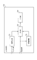
- FIG. 2 illustrates hardware included in the image processing apparatus according to the first embodiment
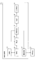
- FIG. 2 is a block diagram showing functions of the image processing apparatus according to Embodiment 1
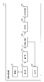
- FIG. 3 is a block diagram showing functions of an analysis creation unit according to Embodiment 1
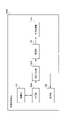
- FIG. 4 is a flowchart showing an example of processing executed by an analysis creation unit according to Embodiment 1
- 3 is a block diagram showing functions of a search unit according to Embodiment 1
- FIG. 4 is a flow chart showing an example of processing executed by a search unit according to Embodiment 1
- 3 is a block diagram showing functions of a determination unit according to Embodiment 1
- FIG. 11 is a block diagram showing functions of an image processing apparatus according to Embodiment 5;
- FIG. 12 is a block diagram showing functions of an image processing apparatus according to Embodiment 6;
- FIG. 21 is a block diagram showing functions of an analysis creation unit according to Embodiment 6;
- FIG. 12 is a block diagram showing functions of an output control unit according to Embodiment 6;
- FIG. 1 illustrates hardware included in an image processing apparatus according to a first embodiment.
- the image processing device 100 is a device that executes an image processing method.
- the image processing apparatus 100 has a processor 101 , a volatile memory device 102 and a nonvolatile memory device 103 .
- the processor 101 controls the image processing apparatus 100 as a whole.
- the processor 101 is a CPU (Central Processing Unit), FPGA (Field Programmable Gate Array), or the like.
- Processor 101 may be a multiprocessor.
- the image processing apparatus 100 may have a processing circuit.
- the processing circuit may be a single circuit or multiple circuits.
- the volatile storage device 102 is the main storage device of the image processing device 100 .
- the volatile memory device 102 is RAM (Random Access Memory).
- a nonvolatile storage device 103 is an auxiliary storage device of the image processing apparatus 100 .
- the nonvolatile storage device 103 is a HDD (Hard Disk Drive) or an SSD (Solid State Drive).
- FIG. 2 is a block diagram showing functions of the image processing apparatus according to the first embodiment.
- the image processing apparatus 100 has a storage unit 110 , an acquisition unit 120 , an analysis creation unit 130 , an inspection unit 140 , an output control unit 150 and a provision unit 160 .
- the storage unit 110 may be realized as a storage area secured in the volatile storage device 102 or the nonvolatile storage device 103.
- a part or all of the acquisition unit 120, the analysis creation unit 130, the inspection unit 140, the output control unit 150, and the provision unit 160 may be implemented by a processing circuit.
- Part or all of the acquisition unit 120 , the analysis creation unit 130 , the inspection unit 140 , the output control unit 150 , and the provision unit 160 may be implemented as modules of programs executed by the processor 101 .
- the program executed by the processor 101 is also called an image processing program.
- an image processing program is recorded on a recording medium.
- the acquisition unit 120 acquires an image.
- the acquisition unit 120 acquires an image from the storage unit 110.
- FIG. Also, for example, the acquisition unit 120 acquires an image from an imaging device. Note that illustration of the imaging device is omitted.
- the acquisition unit 120 acquires a trained model for inspection.
- the acquisition unit 120 acquires the trained model for inspection from the storage unit 110 .
- the trained model for inspection may be stored in an external device (for example, a cloud server).
- the acquisition unit 120 acquires the trained model for inspection from the external device.
- the trained model for inspection is a trained model for inspecting an object to be inspected.
- the trained model for inspection is a trained model for inferring the inspection result of the object included in the image.
- the analysis creation unit 130 uses the image to analyze whether or not the inspection object is included in the image. Specifically, the analysis creation unit 130 uses the image and a preset method to analyze whether or not the object to be inspected is included in the image. For example, the preset methods are pattern matching, general object recognition technology, specific object recognition technology, and the like. The analysis creation unit 130 may create an analysis result indicating that the image is suitable as an image to be used for inspection when the object is included in the image. The analysis creation unit 130 may create an analysis result indicating that the image is not suitable as an image to be used for inspection if the image does not include the target object. Detailed functions of the analysis creation unit 130 will be described later.
- the analysis creating unit 130 outputs the analysis result and the image to the providing unit 160 when the image is not suitable for inspection or when the image is suitable for use in inspection.
- the inspection unit 140 inspects the object included in the image using the image and the trained model for inspection. Specifically, the inspection unit 140 obtains inspection results output by the trained model for inspection by inputting information obtained from the image into the trained model for inspection. It should be noted that, for example, in the inspection, it is inspected whether there is a scratch on the object, whether there is a missing part, or whether there is a work omission. Further, for example, the work omission is forgetting to fasten a screw or insufficient fastening of a screw. Further, the inspection unit 140 may inspect the target object included in the image using the contents of the analysis executed by the analysis creation unit 130, the image, and the inspection trained model.
- the inspection unit 140 uses an image including the object cut out from the image acquired by the acquisition unit 120 (that is, an image from which the background has been removed) and a trained model for inspection to obtain the object may be inspected. As a result, the inspection unit 140 can perform inspection with higher accuracy. Note that when the inspection is performed, in the learning phase, learning for performing the inspection is performed using an image including the cut-out target object. Then, by performing learning, a trained model for inspection used in the inspection is generated.
- the output control unit 150 outputs inspection results. For example, the output control unit 150 outputs inspection results to a display. Further, for example, the output control unit 150 outputs inspection results to an external device. The output control section 150 may output the inspection result to the storage section 110 .
- the providing unit 160 provides information for creating an appropriate image based on the analysis results.
- the analysis result is the result of analyzing the image.
- the analysis result may be expressed as including the analysis result for the analysis target, which will be described later.
- the providing unit 160 provides the user with information indicating that the target is not included in the image. Then, the providing unit 160 provides the user with information prompting the user to take an image so that the target object is included in the image.
- the providing unit 160 provides the user with information indicating that the composition is not appropriate when the object is imaged from the side when the object should be imaged from the front. Then, the providing unit 160 provides the user with information prompting the user to review the composition.
- the providing unit 160 provides the user with information indicating that the brightness and sharpness are not appropriate.
- information provided to the user is displayed on the display. This allows the user to recognize the provided information. Also, the information provided to the user may be provided by voice.
- the information provided by the providing unit 160 allows the user to capture an appropriate image using the imaging device.
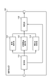
- FIG. 3 is a block diagram showing functions of an analysis creation unit according to the first embodiment.
- the analysis creation unit 130 has a search unit 131 , a composition analysis unit 132 , a lighting environment analysis unit 133 , a sharpness analysis unit 134 and a determination unit 135 . Functions of the search unit 131, the composition analysis unit 132, the illumination environment analysis unit 133, the sharpness analysis unit 134, and the determination unit 135 will be described later.
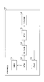
- FIG. 4 is a flowchart illustrating an example of processing executed by an analysis creation unit according to Embodiment 1.
- the searching unit 131 searches for an object in the image using the image acquired by the acquiring unit 120 and a preset method. Specifically, the search unit 131 searches for a region of the object within the image.
- the preset methods are pattern matching, general object recognition technology, specific object recognition technology, and the like.
- Step S12 The search unit 131 determines whether or not the image contains an object. If the image contains the object, the process proceeds to step S13. If the image does not contain the object, the search unit 131 outputs an analysis result indicating that the image is not suitable for inspection. The process then ends.
- the composition analysis unit 132 analyzes the composition of the object based on the area of the object in the image. For example, the composition analysis unit 132 analyzes the positional relationship between the imaging device that generated the image and the object as a composition. Specifically, the composition analysis unit 132 analyzes whether the imaging device is imaging the object from the front or from the side. In addition, you may think that the said positional relationship is a three-dimensional positional relationship. The positional relationship is represented by relative coordinates, but may be represented by absolute coordinates (for example, also called world coordinates). Also, for example, the composition analysis unit 132 analyzes the degree of zoom when the target object is imaged as the composition. Specifically, the composition analysis unit 132 analyzes the size of the captured object.
- the lighting environment analysis unit 133 analyzes the brightness of the area based on the area of the object in the image. In other words, the lighting environment analysis unit 133 analyzes the luminance distribution of the area. Also, in other words, the lighting environment analysis unit 133 analyzes how bright the object appears in the image. Also, the lighting environment analysis unit 133 may analyze the average brightness of the area. Furthermore, the lighting environment analysis unit 133 may analyze how the object is illuminated by lighting based on the area of the object in the image.
- the sharpness analysis unit 134 analyzes the sharpness of the area based on the area of the object in the image. Sharpness is degraded due to defocus in the imaging device and blurring of the imaging device during imaging.
- the sharpness analysis unit 134 may analyze the sharpness for each factor such as out-of-focus and camera shake. When analyzing the sharpness, the sharpness analysis unit 134 may convert the area into frequencies and analyze the sharpness from the values and distribution based on the frequencies.
- Step S14 The determination unit 135 determines whether or not the image is suitable as an image to be used for inspection, based on the composition, brightness, and sharpness (that is, the analysis result of the analysis target). In other words, the determination unit 135 comprehensively determines the composition, brightness, and sharpness to determine whether the image is suitable as an image to be used for inspection.
- the determination unit 135 performs the following processes in the determination process.
- the determination unit 135 compares the analyzed composition with a preset composition.
- the determination unit 135 compares the analyzed brightness with a preset threshold.
- the determination unit 135 compares the analyzed sharpness with a preset threshold.
- the determination unit 135 may input at least one of brightness and sharpness into a formula prepared in advance, and determine whether or not it is appropriate based on the value output by the formula. good.
- the image contains a screw, which is an object.
- the first condition is that the composition is such that the screw, which is the fastening part, and the contact surface of the object to be fastened can be seen from a predetermined angle or more with respect to the fastening direction of the screw.
- the second condition is that the sharpness is such that the groove between the screw and the object to be fastened is clearly detected when the fastening is in a bad state.
- the third condition is that the brightness is such that the groove, screw, and object to be fastened can be distinguished.
- the angle, the sharpness, and the brightness may be determined based on the know-how of a skilled worker, or values may be set so that the trained model for inspection can perform an appropriate inspection.
- the values for the trained model for inspection to perform appropriate inspection may be, for example, values obtained by obtaining the angle, sharpness, and brightness of the object included in the learning data used to generate the trained model for inspection.
- weights may be added to the imaging angle derived from the composition, the analyzed sharpness, and the analyzed luminance.
- the determining unit 135 determines whether or not the image is suitable as an image to be used for inspection based on the weighted total value of the imaging angle, sharpness, and luminance, and a preset value.
- step S15 If the image is suitable as an image to be used for inspection, the process proceeds to step S15. If the image is not suitable for inspection, the determination unit 135 outputs an analysis result indicating that the image is not suitable for inspection. The process then ends.
- Step S15 The determination unit 135 outputs to the inspection unit 140 an analysis result indicating that the image is suitable as an image used for inspection, area information indicating the area of the object in the image, and the image. Also, the region information may be included in the analysis result. It can be said that the analysis result is created by the analysis creating unit 130 .
- the image processing apparatus 100 determines whether or not the image is suitable as an image to be used for inspection, even if the image contains an object. As a result, the image processing apparatus 100 can prevent inspection using inappropriate images.
- the search unit 131 may have the following functions.
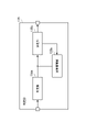
- 5 is a block diagram showing functions of a search unit according to Embodiment 1.
- the search unit 131 has an image storage unit 131a, a search result storage unit 131b, a search processing unit 131c, and a determination unit 131d. Note that the image storage unit 131a and the search result storage unit 131b may be realized by the storage unit 110.
- FIG. 5 is a block diagram showing functions of a search unit according to Embodiment 1.
- the search unit 131 has an image storage unit 131a, a search result storage unit 131b, a search processing unit 131c, and a determination unit 131d. Note that the image storage unit 131a and the search result storage unit 131b may be realized by the storage unit 110.
- the acquisition unit 120 acquires a plurality of images obtained by continuously imaging the object.
- the plurality of images are 30 images obtained by continuously imaging the object in one second. That is, the plurality of images are images obtained by continuous shooting by the imaging device. Also, the plurality of images may be a plurality of frames forming a moving image.
- the image accumulating unit 131a accumulates past images, which are images in which the target object has been searched, among the plurality of images. Since the past image is an image obtained by continuous shooting, the time at which the past image was created does not differ greatly from the time at which the current image, which will be described later, was created. The past image contains the same objects as the current image. Also, the positions of the objects included in the past image and the current image do not change significantly. A preset number of images are accumulated in the image accumulation unit 131a. If the number is exceeded, the oldest images are deleted. When a plurality of similar images are stored in the image storage unit 131a, the plurality of images may be preferentially deleted. This is because different images are stored in the image storage unit 131a as much as possible.
- the similarity is determined based on whether or not the average of the absolute differences of the pixel values is equal to or less than a certain value.
- the images stored in the image storage unit 131a may be deleted when a preset period has elapsed.
- the search result accumulation unit 131b accumulates search results for past images. Also, the search results stored in the search result storage unit 131b are deleted in chronological order.
- the search processing unit 131c searches for an object in the current image, which is an image that has not been searched among the plurality of images.
- the search method is the same as in step S11.
- the search processing unit 131c may search for an object in the current image based on the past image and the search result for the past image. For example, assume that the current image was created at time t. Let f(t-1) be the search result for the past image created at time t-1. Let f(t-2) be the search result for the past image created at time t-2. The search result f(t) for the current image is estimated as "f(t-1)+ ⁇ f(t-1)-f(t-2) ⁇ ". Note that "f(t-1)+ ⁇ f(t-1)-f(t-2) ⁇ " is obtained when the difference between "t-1" and "t-2" is minute, and when the imaging device and the object do not change abruptly. Thereby, the search processing unit 131c can search for the object in the current image. Further, the search processing unit 131c may use the search result obtained by adding a weight to the search result for the past image as the search result for the current image.
- the determining unit 131d Based on the past image, the search result for the past image, and the search result for the current image, the determining unit 131d compares the position of the object in the current image with the position of the object in the past image, and determines the error. is less than a preset threshold, output the search result for the current image. If the error is equal to or greater than the threshold, the determination unit 131d determines the average of the positions of the object in the current image and the positions of the object in the past image as the search result for the current image. The determining unit 131d may add a weight to the average.
- the determination unit 131d groups the target object region in the current image and the target object region in the previous image, and selects the target object region from among the grouped regions by a majority vote. may be determined, and the determined region may be determined as the search result for the current image.
- the determination unit 131d stores the search result in the search result accumulation unit 131b.
- FIG. 6 is a flowchart illustrating an example of processing executed by a search unit according to Embodiment 1.
- the search processing unit 131c acquires past images from the image storage unit 131a.
- the search processing unit 131c acquires search results for past images from the search result accumulation unit 131b.
- Step S23 The search processing unit 131c searches for an object within the current image.
- Step S24 Based on the past image, the search result for the past image, and the search result for the current image, the determination unit 131d determines the position of the object in the current image and the position of the object in the past image. compare.
- Step S25 The determination unit 131d determines whether the error is smaller than the threshold. If the error is smaller than the threshold, the process proceeds to step S26. If the error is greater than or equal to the threshold, the process proceeds to step S27.
- Step S26 The determination unit 131d outputs the search result for the current image.
- Step S27 The determining unit 131d determines the average of the position of the object in the current image and the positions of the object in one or more past images as the search result for the current image. Note that the method using the average is an example. In this manner, the image processing apparatus 100 adjusts the search result for the current image when the search result for the current image is unsatisfactory. Accordingly, the image processing apparatus 100 analyzes the sharpness and the like for the region indicated by the adjusted search result. Therefore, the image processing apparatus 100 can perform appropriate analysis.
- step S26 or step S27 the composition, brightness, and sharpness are analyzed based on the area indicated by the search result for the current image. For example, after step S26, composition, brightness and sharpness are analyzed based on the area of the object in the current image.
- the determination unit 135 may have the following functions. 7 is a block diagram illustrating functions of a determination unit according to Embodiment 1.
- FIG. The determination unit 135 has a determination unit 135a, a result accumulation unit 135b, and a determination unit 135c. Note that the result storage unit 135b may be realized by the storage unit 110.
- FIG. 7 is a block diagram illustrating functions of a determination unit according to Embodiment 1.
- the determination unit 135 has a determination unit 135a, a result accumulation unit 135b, and a determination unit 135c. Note that the result storage unit 135b may be realized by the storage unit 110.
- the determining unit 135a determines whether the current image is suitable as an image to be used for inspection, based on the composition, brightness, and sharpness obtained by analyzing the current image (that is, results to be analyzed). judge. Specifically, the determination unit 135a performs the same processing as in step S14.
- the result accumulation unit 135b accumulates past determination results indicating whether or not the past image is suitable as an image to be used for inspection.
- the past determination results are deleted in chronological order when a preset number or a preset period has passed.
- the determination unit 135c compares the past determination result and the current determination result indicating whether or not the current image is suitable as an image to be used for inspection, and outputs the current determination result when the determination results match. If the determination results do not match, the determination unit 135c performs a majority vote based on the past determination result and the current determination result, and determines the determination result based on the majority vote as the current determination result.
- the current image is one of a plurality of images obtained by continuously capturing images. Since images are captured at short intervals, it is considered that the determination result does not change. Therefore, the image processing apparatus 100 matches the current determination result with the past determination result. Thereby, the image processing apparatus 100 can adjust the determination result even when the accuracy of the determination unit 135a is not preferable.
- the determination unit 135c stores the current determination result in the result accumulation unit 135b.
- FIG. 8 is a flowchart illustrating an example of processing executed by a determination unit according to Embodiment 1.
- Step S31 Based on the composition, brightness, and sharpness obtained by analyzing the current image, the determination unit 135a determines whether the current image is suitable as an image to be used for inspection.
- Step S32 The determining unit 135c acquires the past determination result from the result accumulating unit 135b.
- Step S33 The determination unit 135c compares the past determination result and the current determination result.
- Step S34 The determination unit 135c determines whether the determination results match. If the determination results match, the process proceeds to step S35. If the determination result does not match, the process proceeds to step S36.
- Step S35 The determination unit 135c outputs the current determination result.
- Step S36 The determination unit 135c performs a majority vote based on the past determination result and the current determination result, and determines the determination result based on the majority vote as the current determination result.
- the image processing apparatus 100 does not perform inspection when the image does not include the target object.
- the image processing apparatus 100 performs inspection when an object is included in the image. Therefore, the image processing apparatus 100 can perform appropriate inspection.
- the image processing apparatus 100 determines that the image is suitable as an image to be used for inspection based on the composition, brightness, and sharpness even if the image contains an object. Determine whether or not As a result, the image processing apparatus 100 can prevent inspection using inappropriate images.
- Embodiment 1 a case will be described in which the function of the analysis creation unit 130 is realized by a learned model.
- the learned model is called a learned model for analysis.
- a trained model for analysis is a trained model for inferring whether an image is suitable as an image to be used for inspection.
- the learning phase for creating a trained model for analysis and a trained model for inspection will be explained.
- an image, an analysis result having the same content as the content output by the analysis creating unit 130, and an inspection result having the same content as the content output from the inspection unit 140 are prepared as learning data.
- the suitable image may be used as learning data.
- the learning data may be selected by the user. For example, the user selects an image for which an analysis result indicating that it is a suitable image is output. For example, in the inspection, the screw fastening is inspected based on the clearance of the spring washer portion. Therefore, the user selects an image in which the brightness and sharpness of the spring washer portion are appropriate.
- the trained model for analysis In the learning phase, if the trained model for inspection outputs an incorrect inspection result, the trained model for analysis is retrained so that it outputs an analysis result indicating that the trained model for analysis is not a suitable image. . Also, the trained model for analysis and the trained model for inspection may be generated separately.
- a trained model for analysis that infers an image analysis result from an image is generated by machine learning using combinations of images and image analysis results as learning data.
- a trained model for inspection that infers an inspection result of an object from an image is generated by machine learning using a combination of an image and an inspection result as learning data.
- Machine learning is performed by a learning device (not shown). The learning device may be built in the image processing device, or may be stored in an external device. Known algorithms such as supervised learning, unsupervised learning, and reinforcement learning can be used as the learning algorithm used by the learning device. In supervised learning, for example, neural network models can be used.
- the learned model for analysis is acquired by the acquisition unit 120.
- the acquisition unit 120 acquires the learned model for analysis from the storage unit 110 .
- the learned model for analysis may be stored in an external device.
- the obtaining unit 120 obtains the trained model for analysis from the external device.
- the analysis creation unit 130 uses the image and the trained model for analysis to analyze whether the image is suitable as an image to be used for inspection. Specifically, the analysis creation unit 130 inputs information based on the image to the trained model for analysis, so that the trained model for analysis generates an analysis result as to whether or not the image is suitable as an image to be used for inspection. Output.
- the analytical trained model has the same function as the analysis creation unit 130 . Therefore, the modified example of the first embodiment has the same effect as the first embodiment even if the trained model for analysis is used.
- Embodiment 2 Next, Embodiment 2 will be described. In Embodiment 2, mainly matters different from Embodiment 1 will be described. In the second embodiment, descriptions of items common to the first embodiment are omitted.
- FIG. 9 is a block diagram showing functions of the image processing apparatus according to the second embodiment. 9 that are the same as those shown in FIG. 2 are given the same reference numerals as those shown in FIG.
- the image processing device 100 a is connected to the imaging device 200 .
- the image processing device 100 a has an imaging control section 170 .
- a part or all of the imaging control unit 170 may be realized by a processing circuit. Also, part or all of the imaging control unit 170 may be realized as a module of a program executed by the processor 101 .
- the analysis creation unit 130 outputs the analysis result to the imaging control unit 170 when the image is not suitable for use in inspection and when the image is suitable for use in inspection.
- the imaging control unit 170 controls the imaging device 200 so that the imaging device 200 creates an appropriate image based on the analysis result. Detailed functions of the imaging control unit 170 will be described.
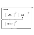
- FIG. 10 is a block diagram illustrating functions of an imaging control unit according to Embodiment 2.
- the imaging control section 170 has an exposure adjustment section 171 , a focus adjustment section 172 and a composition control section 173 .
- the exposure adjustment unit 171 adjusts parameters related to exposure based on the luminance indicated by the analysis result. For example, the parameters are aperture, shutter speed, shooting sensitivity, and the like.
- the exposure adjustment unit 171 adjusts the parameters so as to obtain a predetermined brightness.
- the exposure adjustment section 171 may adjust parameters based on information regarding the characteristics of the imaging device 200 .
- the focus adjustment unit 172 adjusts the focus of the imaging device 200 based on the sharpness indicated by the analysis result and the area of the object in the image. Specifically, the focus adjustment unit 172 adjusts the focus of the imaging device 200 so that the sharpness of the region is high.
- the composition control unit 173 controls the imaging device 200 based on the composition indicated by the analysis result. For example, the composition control unit 173 controls the zoom function of the imaging device 200 based on the composition. Further, for example, when changing the composition, the composition control unit 173 controls the movable units connected to the imaging device 200 based on the composition.
- the imaging control unit 170 may provide the user with the parameters, information on focus, information on zoom, and information for changing the movable part.
- the imaging control unit 170 may control the imaging device 200 so that the imaging device 200 creates a plurality of images with different exposures, different focuses, and different compositions.
- the acquisition unit 120 can acquire a plurality of images obtained by imaging in different states.
- the analysis/creation unit 130 analyzes each of the plurality of images to determine whether they are suitable images for use in inspection. In this manner, the image processing apparatus 100a can reduce inappropriate images for use in inspection by causing the imaging apparatus 200 to create a plurality of images that are images of different variations.
- the plurality of images obtained by imaging in different states may be a plurality of images obtained by continuously imaging the object. That is, the plurality of images may be a plurality of images obtained by continuously imaging the object in different states.
- the determination unit 131d determines the position of the object in the current image and the position of the object in the past image based on the search result for the past image among the plurality of images and the search result for the current image among the plurality of images. is greater than or equal to a preset threshold, the average of the position of the object in the current image and the position of the object in one or more past images is determined as the search result for the current image.
- the determination unit 135c compares the past determination result and the current determination result, and if the determination results do not match, performs a majority vote based on the past determination result and the current determination result, and determines the determination result based on the majority vote as the current determination result. You may decide as a judgment result.
- Embodiment 3 Next, Embodiment 3 will be described. In Embodiment 3, mainly matters different from Embodiments 1 and 2 will be described. In the third embodiment, descriptions of items common to the first and second embodiments are omitted.
- FIG. 11 is a block diagram showing functions of the image processing apparatus according to the third embodiment. 11 that are the same as those shown in FIG. 2 are given the same reference numerals as those shown in FIG.
- the image processing device 100b has a correction section 180.
- FIG. A part or all of the correction unit 180 may be implemented by a processing circuit. Also, part or all of the correction unit 180 may be realized as a module of a program executed by the processor 101 .
- the acquisition unit 120 acquires a plurality of images obtained by continuously imaging the object.
- Analysis creating unit 130 creates an analysis result for a first image among the plurality of images.
- the correction unit 180 corrects the second image, which is one of the plurality of images and is the image created after the first image, based on the analysis result. For example, if the analysis result indicates that the analyzed brightness is lower than the threshold, the correction unit 180 performs correction to make the brightness of the second image equal to or higher than the threshold. For example, when the analysis result indicates that the analyzed sharpness is smaller than the threshold, the correction unit 180 performs correction to make the sharpness of the second image equal to or higher than the threshold. By correcting the second image by the image processing apparatus 100b in this manner, the second image becomes an image suitable for inspection.
- the correction unit 180 may correct the first image based on the analysis result.
- a plurality of images may be a plurality of images obtained by continuously imaging an object in different states. That is, the plurality of images may be images of different variations created by the imaging device 200 .
- the correction unit 180 may correct all or part of the plurality of images. For example, the correction unit 180 corrects the multiple images based on the average noise amount of each of the multiple images. This reduces the overall noise in the multiple images. Further, for example, the correcting unit 180 adds a weight to the average luminance of each of the plurality of images, and corrects the plurality of images based on the value obtained by adding the weight. In this manner, the image processing apparatus 100b can perform correction within a range that cannot be corrected with one image.
- Embodiment 4 Next, Embodiment 4 will be described. In Embodiment 4, mainly matters different from Embodiment 1 will be described. In the fourth embodiment, descriptions of items common to the first embodiment are omitted.
- FIG. 12 is a block diagram showing functions of the image processing apparatus according to the fourth embodiment. 12 that are the same as those shown in FIG. 2 are assigned the same reference numerals as those shown in FIG.
- the image processing device 100c has an acquisition unit 120c, an analysis creation unit 130c, and an inspection unit 140c.
- the acquisition unit 120c acquires sensor information.
- the acquisition unit 120c acquires sensor information from a sensor.
- the sensor is attached to the imaging device or to the exterior of the imaging device.
- the sensor senses the state of the imaging device and the worker.
- Sensor information is information obtained by detection by a sensor.
- the sensor information is information obtained by measuring by the sensor.
- the sensor information includes information indicating the movement of the worker and the imaging device (for example, gyro information), information indicating the line-of-sight direction of the worker, and information indicating the illuminance of the area imaged by the imaging device. , information indicating the distance from the imaging device to the area imaged by the imaging device, and the like.
- the image processing device 100c can detect a three-dimensional positional relationship including the orientation of the sensor and the imaging device. For example, the image processing device 100c can detect the three-dimensional positional relationship based on sensor information obtained by cooperation between a sensor attached to the imaging device and a sensor attached to the outside of the imaging device. Also, for example, the image processing device 100c can detect a three-dimensional positional relationship by calculating the position of the imaging device based on sensor information obtained from a sensor attached to the outside of the imaging device.
- the acquiring unit 120c acquires an image and a trained model for inspection in the same manner as in the first to third embodiments.
- the analysis creation unit 130c (more specifically, the search unit 131) analyzes whether or not the target object is included in the image based on the sensor information and the image. For example, when the line-of-sight detection sensor and the photographing device are integrated, the sensor information includes the line-of-sight information of the worker. The analysis creation unit 130c detects the area that the worker is looking at in the image based on the line-of-sight information. The area viewed by the worker can be said to be the area where the object exists. Therefore, the analysis creation unit 130c analyzes that the object exists in the area. As a result, the analysis creation unit 130c analyzes that the image includes the object.
- the analysis creation unit 130c analyzes the composition, brightness, and sharpness based on the sensor information and the image.
- the analysis creation unit 130c will be described in detail.
- FIG. 13 is a block diagram showing functions of an analysis creating unit according to the fourth embodiment.
- An image and sensor information are input to the analysis creation unit 130c.
- the composition analysis unit 132 analyzes the positional relationship between the imaging device and the object as a composition based on the movement of the imaging device indicated by the sensor information. Specifically, the composition analysis unit 132 specifies the current position of the imaging device by temporally adding the position where the imaging device moves based on the position information of the imaging device at a certain point in time. The composition analysis unit 132 analyzes the positional relationship between the current position of the imaging device and the position of the object based on the reference position of the imaging device and the position of the object.
- the composition analysis unit 132 may use the composition obtained by adding weight to the composition based on the sensor information as the composition based on the image. Also, the composition analysis unit 132 may add weights to search results for past images to search for objects in the current image.
- the lighting environment analysis unit 133 analyzes the brightness of the area where the object exists based on the sensor information.
- the sensor information is the exposure of the imaging device.
- the sensor information is illuminance information.
- the lighting environment analysis unit 133 adds weights to the brightness based on the image and the brightness based on the sensor information, and analyzes the average of the added values as the brightness input to the determination unit 135 .
- the sharpness analysis unit 134 analyzes the sharpness of the area where the object exists based on the sensor information. For example, the sharpness analysis unit 134 analyzes the amount of blurring based on the movement of the imaging device indicated by the sensor information. The sharpness analysis unit 134 analyzes the sharpness based on this amount. Also, for example, when the sensor information is information indicating the distance from the imaging device to the area being imaged by the imaging device, the sharpness analysis unit 134 analyzes the defocus based on the distance. The sharpness analysis unit 134 analyzes the sharpness based on the defocus. For example, the sharpness analysis unit 134 adds weights to the sharpness based on the image and the sharpness based on the sensor information, and analyzes the average of the added values as the sharpness input to the determination unit 135. .
- the searching unit 131 may perform the following processing.
- 14 is a flowchart illustrating an example of processing executed by a search unit according to Embodiment 4.
- FIG. 14 the acquisition unit 120c acquires a plurality of images obtained by continuously capturing images of the object.
- Step S41 The search processing unit 131c acquires a first image, which is a past image, from the image storage unit 131a. Note that the first image is one of the plurality of images.
- Step S42 The search processing unit 131c acquires the search result for the first image from the search result accumulation unit 131b.
- Step S43 The search processing unit 131c searches for an object in the second image created after the first image.
- Step S44 The search processing unit 131c identifies the current position of the imaging device based on the motion of the imaging device indicated by the sensor information.
- Step S45 The search processing unit 131c calculates the difference between the past position of the imaging device specified based on the sensor information obtained last time and the current position of the imaging device. The difference can be considered as the amount of movement of the object.
- Step S46 The search processing unit 131c identifies the current position of the object based on the search result for the first image and the difference. That is, the search processing unit 131c identifies the current position of the target object by adding the difference to the position of the target object included in the first image.
- Step S47 The determination unit 131d compares the position of the object in the second image searched in step S43 with the current position of the object identified in step S46, and calculates an error.
- Step S48 The determination unit 131d determines whether the error is smaller than the threshold. If the error is smaller than the threshold, the process proceeds to step S49. If the error is greater than or equal to the threshold, the process proceeds to step S50.
- Step S49 The determination unit 131d outputs the search result for the second image.
- Step S50 The determination unit 131d determines the average of the position of the object in the second image and the current position of the object as the search result for the second image. In this way, the image processing device 100c adjusts the search result for the second image when the search result for the second image is unsatisfactory. Accordingly, the image processing device 100d analyzes the sharpness and the like for the region indicated by the adjusted search result. Therefore, the image processing device 100d can perform appropriate analysis.
- the determination unit 131d may create an analysis result indicating that the second image is not suitable as an image used for inspection.
- the search unit 131 searches using template matching, it is determined whether or not there is matching based on the degree of similarity. If the shooting environment when the template image is created and the shooting environment when the acquired image is created are different, the degree of similarity will be affected. Therefore, the search unit 131 calculates the degree of similarity in consideration of the exposure information indicated by the sensor information. This improves search accuracy.
- the inspection unit 140c inspects the object included in the image using the sensor information, the image, and the trained model for inspection. .
- the inspection unit 140c can improve inspection accuracy by using the sensor information. For example, when an object included in an image with low illuminance is inspected without using sensor information, inspection accuracy may be low. Therefore, when the inspection unit 140c inspects an object included in an image with low illuminance using the illuminance indicated by the sensor information, the inspection unit 140c inspects the object in consideration of the sensor information. As a result, the inspection unit 140c can output inspection results with high inspection accuracy.
- the providing unit 160 may be replaced with the imaging control unit 170 .
- the imaging control unit 170 may perform focus adjustment based on the sensor information.
- the imaging control unit 170 may adjust the exposure based on the illuminance information indicated by the sensor information.
- the imaging control unit 170 may control the imaging device based on sensor information and analysis results.
- the image processing device 100c can perform highly accurate analysis by using sensor information.
- Embodiment 5 Next, Embodiment 5 will be described. In Embodiment 5, mainly matters different from those in Embodiment 4 will be described. Further, in the fifth embodiment, descriptions of matters common to the fourth embodiment are omitted.
- FIG. 15 is a block diagram showing functions of the image processing apparatus according to the fifth embodiment. 15 that are the same as the configuration shown in FIG. 12 are assigned the same reference numerals as those shown in FIG.
- the image processing device 100c further has a correction unit 180c.
- the correction unit 180c uses the sensor information to correct the image acquired by the acquisition unit 120c. For example, the correction unit 180c calculates the direction and magnitude of blur caused by the motion of the imaging device based on the motion of the imaging device indicated by the sensor information, and corrects the image based on the calculated result. . Specifically, the correction unit 180c calculates the point spread function h based on the blur direction and blur magnitude.
- F be the Fourier transform for image f.
- H the Fourier transform for the point spread function h.
- the correction unit 180c may correct the sharpness of the image using the sensor information. Further, the correction unit 180c may correct the brightness of the image based on the illuminance indicated by the sensor information. The correction unit 180c may correct the image based on the analysis result created by the analysis creation unit 130c and the sensor information.
- the image processing apparatus 100c corrects the image using sensor information, thereby increasing the probability that the image is determined to be suitable for use in inspection.
- Embodiment 6 Next, Embodiment 6 will be described. In Embodiment 6, mainly matters different from those in Embodiment 1 will be described. Further, in the sixth embodiment, descriptions of matters common to the first embodiment are omitted.
- FIG. 16 is a block diagram showing functions of the image processing apparatus according to the sixth embodiment. 16 that are the same as those shown in FIG. 2 are assigned the same reference numerals as those shown in FIG.
- the image processing device 100d has an acquisition unit 120d, an analysis creation unit 130d, and an output control unit 150d.
- the acquisition unit 120d acquires sensor information.
- the acquisition unit 120d also acquires drawing information.
- the acquisition unit 120d acquires drawing information from a server.
- the drawing information is 3D-CAD.
- Drawing information includes one or more objects.
- the drawing information is information related to design such as various dimensions and tolerances of the fastening portion of the screw, which is the object, and the object to be fastened, and indicates the whole or part of the product.
- the acquisition unit 120d acquires an image and a trained model for inspection as in the first embodiment.
- FIG. 17 is a block diagram showing functions of an analysis creating unit according to the sixth embodiment.
- An image, sensor information, and drawing information are input to the analysis creation unit 130d.
- Analysis creation unit 130 d has coordinate processing unit 136 .
- the coordinate processing unit 136 aligns the coordinate system of the drawing information with the coordinate system of the image using the image, the sensor information, and the drawing information.
- the combined coordinate system will be referred to as the world coordinate system.
- a predetermined position is set as the origin of the world coordinate system.
- a feature point of the object indicated by the drawing information may be set at the origin of the world coordinate system.
- the coordinate processing unit 136 calculates coordinates of feature points in the world coordinate system.
- the coordinate processing unit 136 calculates the coordinates of the feature points based on the distances between the origin and the feature points.
- the coordinate processing unit 136 also calculates the coordinates of each pixel of the image in the world coordinate system based on the sensor information. For example, if the sensor is a gyro sensor, the coordinate processing unit 136 calculates the coordinates of each pixel in the world coordinate system based on the orientation of the imaging device indicated by the sensor information.
- the search processing unit 131c of the search unit 131 searches for an object included in the image based on the coordinates of the object included in the drawing information. Since the same coordinate system is used in this way, the search processing unit 131c can search for the object included in the image based on the drawing information. Further, when the drawing information includes position information of an object (for example, a screw), the search processing unit 131c converts the position information into the world coordinate system, and based on the converted position information, Contained objects (eg, screws) may be searched.
- an object for example, a screw
- the search processing unit 131c searches for an object included in the image based on the image.
- the search processing unit 131c compares the position of the object searched based on the drawing information and the position of the object searched based on the image to calculate an error.
- the determination unit 131d outputs the search result based on the image when the error is smaller than the threshold. If the error is equal to or greater than the threshold, the determination unit 131d determines the average of the positions of the object searched based on the drawing information and the positions of the object searched based on the image as the search result for the image. may In this way, the image processing device 100d adjusts the search result for the image when the search result for the image is unsatisfactory. Accordingly, the image processing device 100d analyzes the sharpness and the like for the region indicated by the adjusted search result. Therefore, the image processing device 100d can perform appropriate analysis.
- the search unit 131 outputs the search result and the coordinate information in association with each other. If the determining unit 135 determines that the image is suitable as an image to be used for inspection, the determining unit 135 associates the analysis result, the image, and the coordinate information and outputs them.
- FIG. 18 is a block diagram showing functions of an output control unit according to the sixth embodiment.
- the output control unit 150 d has a view specifying unit 151 , a result accumulation unit 152 , a determination unit 153 and an output unit 154 .
- the visual field identification unit 151 identifies the visual field and visual field area of the worker based on the line-of-sight information indicated by the sensor information.
- the result accumulation unit 152 accumulates inspection results. When the preset number is exceeded, the oldest test results are deleted.
- the decision unit 153 may decide whether to provide the inspection result to the worker.
- the determination part 153 determines the provision timing. For example, the determining unit 153 detects whether or not the worker is working based on the information specified by the visual field specifying unit 151, and determines the provision timing based on the detection result.
- the determining unit 153 determines to output the current inspection result when the current inspection result is different from the past inspection result. That is, when the test result changes, the determination unit 153 controls to output the test result. This prevents the operator from being unable to recognize the display content due to frequent switching of the display content.
- the decision unit 153 may decide to output the current test result and the past test result at the same time. For example, when the past inspection object is the screw A and the current inspection object is the screw B, the determining unit 153 determines to output the inspection result of the screw A and the inspection result of the screw B at the same time. .
- the decision unit 153 decides where to output the analysis results. For example, the determining unit 153 determines to output to a display viewed by the worker. Also, the determining unit 153 may determine to display the analysis results in a list format at the edge of the display. When the output target is a see-through type head-mounted type MR (Mixed Reality) device, the determining unit 153 identifies the target based on the coordinate information, and superimposes the analysis result on the target using a superimposed display method. may be determined.
- the output unit 154 outputs the analysis result based on the content of the decision made by the decision unit 153 . Also, the output unit 154 may output information indicating whether or not all inspection objects have been inspected, which is included in the drawing information. Also, the output unit 154 may output the information of the object indicated by the drawing information and the 3D model of the object.
- compositions, brightness, and sharpness are analyzed. At least one of composition, brightness, and sharpness may be analyzed. Note that at least one of composition, brightness, and sharpness is also called an analysis target.
- Embodiment 1 the case where the trained model for analysis is used has been described.
- Embodiments 2 to 6 a trained model for analysis may be used.
- the trained model for analysis has the same functions as the analysis creation units of the second to sixth embodiments.
Landscapes
- Engineering & Computer Science (AREA)
- General Physics & Mathematics (AREA)
- Physics & Mathematics (AREA)
- Theoretical Computer Science (AREA)
- Computer Vision & Pattern Recognition (AREA)
- Quality & Reliability (AREA)
- Analytical Chemistry (AREA)
- General Health & Medical Sciences (AREA)
- Immunology (AREA)
- Pathology (AREA)
- Biochemistry (AREA)
- Chemical & Material Sciences (AREA)
- Life Sciences & Earth Sciences (AREA)
- Health & Medical Sciences (AREA)
- Image Analysis (AREA)
- Investigating Materials By The Use Of Optical Means Adapted For Particular Applications (AREA)
Abstract
Description
図1は、実施の形態1の画像処理装置が有するハードウェアを示す図である。画像処理装置100は、画像処理方法を実行する装置である。画像処理装置100は、プロセッサ101、揮発性記憶装置102、及び不揮発性記憶装置103を有する。
図2は、実施の形態1の画像処理装置の機能を示すブロック図である。画像処理装置100は、記憶部110、取得部120、解析作成部130、検査部140、及び出力制御部150、及び提供部160を有する。
解析作成部130の詳細な機能は、後で説明する。
また、検査部140は、解析作成部130で実行された解析の内容と、画像と、検査用学習済モデルとを用いて、画像に含まれる対象物を検査してもよい。さらに、検査部140は、取得部120によって取得された画像から、切り出された対象物を含む画像(すなわち、背景が削除された画像)と、検査用学習済モデルとを用いて、当該対象物を検査してもよい。これにより、検査部140は、より精度の高い検査を行うことができる。なお、当該検査が行われる場合、学習フェーズでは、切り出された対象物を含む画像を用いて検査を行うための学習が行われる。そして、学習が行われることで、当該検査で用いられる検査用学習済モデルが、生成される。
図3は、実施の形態1の解析作成部の機能を示すブロック図である。解析作成部130は、探索部131、構図解析部132、照明環境解析部133、鮮鋭度解析部134、及び判定部135を有する。
探索部131、構図解析部132、照明環境解析部133、鮮鋭度解析部134、及び判定部135の機能は、後で説明する。
(ステップS11)探索部131は、取得部120が取得した画像と予め設定された方法とを用いて、画像内の対象物を探索する。詳細には、探索部131は、画像内の対象物の領域を探索する。例えば、予め設定された方法は、パターンマッチング、一般物体認識技術、特定物体認識技術などである。
図5は、実施の形態1の探索部の機能を示すブロック図である。探索部131は、画像蓄積部131a、探索結果蓄積部131b、探索処理部131c、及び決定部131dを有する。なお、画像蓄積部131a及び探索結果蓄積部131bは、記憶部110で実現されてもよい。
決定部131dは、探索結果を探索結果蓄積部131bに格納する。
(ステップS21)探索処理部131cは、画像蓄積部131aから過去画像を取得する。
(ステップS22)探索処理部131cは、探索結果蓄積部131bから過去画像に対する探索結果を取得する。
(ステップS24)決定部131dは、過去画像と、過去画像に対する探索結果と、現在画像に対する探索結果とに基づいて、現在画像内の対象物の位置と、過去画像内の対象物の位置とを比較する。
(ステップS25)決定部131dは、誤差が当該閾値よりも小さいか否かを判定する。誤差が当該閾値よりも小さい場合、処理は、ステップS26に進む。誤差が当該閾値以上である場合、処理は、ステップS27に進む。
(ステップS27)決定部131dは、現在画像内の対象物の位置と、1以上の過去画像内の対象物の位置との平均を、現在画像に対する探索結果として決定する。なお、平均を用いる方法は、一例である。このように、画像処理装置100は、現在画像に対する探索結果が思わしくない場合、現在画像に対する探索結果を調整する。これにより、画像処理装置100は、調整された探索結果が示す領域に対して、鮮鋭度などの解析を行う。よって、画像処理装置100は、適切な解析を行える。
図7は、実施の形態1の判定部の機能を示すブロック図である。判定部135は、判定部135a、結果蓄積部135b、及び決定部135cを有する。なお、結果蓄積部135bは、記憶部110で実現されてもよい。
決定部135cは、現在判定結果を結果蓄積部135bに格納する。
(ステップS31)判定部135aは、現在画像を解析することにより得られた構図、輝度、及び鮮鋭度に基づいて、現在画像が検査に用いられる画像として適当であるか否かを判定する。
(ステップS32)決定部135cは、過去判定結果を結果蓄積部135bから取得する。
(ステップS34)決定部135cは、判定結果が一致するか否かを判定する。判定結果が一致する場合、処理は、ステップS35に進む。判定結果が一致しない場合、処理は、ステップS36に進む。
(ステップS35)決定部135cは、現在判定結果を出力する。
(ステップS36)決定部135cは、過去判定結果と現在判定結果とに基づいて、多数決を行い、多数決に基づく判定結果を、現在判定結果として決定する。
また、実施の形態1によれば、画像処理装置100は、画像に対象物が含まれている場合でも、構図、輝度、及び鮮鋭度に基づいて、画像が検査に用いられる画像として適当であるか否かを判定する。これにより、画像処理装置100は、適当でない画像を用いた検査を防止できる。
実施の形態1の変形例では、解析作成部130の機能が学習済モデルで実現される場合を説明する。ここで、当該学習済モデルは、解析用学習済モデルと呼ぶ。解析用学習済モデルは、画像が検査に用いられる画像として適切であるか否かを推論するための学習済モデルである。
機械学習は、図示しない学習装置により行われる。学習装置は、画像処理装置に内蔵されてもよいし、外部装置に格納されてもよい。学習装置が用いる学習アルゴリズムは、教師あり学習、教師なし学習、強化学習等の公知のアルゴリズムを用いることができる。教師あり学習では、例えば、ニューラルネットワークモデルを利用することができる。
よって、実施の形態1の変形例は、解析用学習済モデルが用いられても、実施の形態1と同じ効果を奏する。
次に、実施の形態2を説明する。実施の形態2では、実施の形態1と相違する事項を主に説明する。そして、実施の形態2では、実施の形態1と共通する事項の説明を省略する。
画像処理装置100aは、撮像装置200と接続する。画像処理装置100aは、撮像制御部170を有する。
撮像制御部170の一部又は全部は、処理回路によって実現してもよい。また、撮像制御部170の一部又は全部は、プロセッサ101が実行するプログラムのモジュールとして実現してもよい。
撮像制御部170は、解析結果に基づいて、撮像装置200が適当な画像を作成するために、撮像装置200を制御する。撮像制御部170の詳細な機能を説明する。
露出調整部171は、解析結果が示す輝度に基づいて、露出に関するパラメータを調整する。例えば、パラメータは、絞り、シャッター速度、撮影感度などである。露出調整部171は、予め決められた輝度になるように、パラメータを調整する。また、露出調整部171は、撮像装置200の特性に関する情報に基づいて、パラメータを調整してもよい。
構図制御部173は、解析結果が示す構図に基づいて、撮像装置200を制御する。例えば、構図制御部173は、構図に基づいて、撮像装置200のズーム機能を制御する。また、例えば、構図を変更する場合、構図制御部173は、構図に基づいて、撮像装置200に接続されている可動部を制御する。
次に、実施の形態3を説明する。実施の形態3では、実施の形態1,2と相違する事項を主に説明する。そして、実施の形態3では、実施の形態1,2と共通する事項の説明を省略する。
画像処理装置100bは、補正部180を有する。補正部180の一部又は全部は、処理回路によって実現してもよい。また、補正部180の一部又は全部は、プロセッサ101が実行するプログラムのモジュールとして実現してもよい。
解析作成部130は、複数の画像のうちの第1の画像に対する解析結果を作成する。
次に、実施の形態4を説明する。実施の形態4では、実施の形態1と相違する事項を主に説明する。そして、実施の形態4では、実施の形態1と共通する事項の説明を省略する。
なお、取得部120cは、実施の形態1~3と同様に、画像及び検査用学習済モデルを取得する。
構図解析部132は、センサ情報が示す撮像装置の動きに基づいて、撮像装置と対象物との位置関係を、構図として解析する。詳細には、構図解析部132は、ある時点の撮像装置の位置情報を基準に、撮像装置が動く位置を時間的に加算することで、現在の撮像装置の位置を特定する。構図解析部132は、撮像装置の基準位置と、対象物の位置とに基づいて、撮像装置の現在位置と対象物の位置との位置関係を解析する。
図14は、実施の形態4の探索部が実行する処理の例を示すフローチャートである。図14の処理では、取得部120cによって、対象物を連続して撮像することにより得られた複数の画像が取得されている。
(ステップS42)探索処理部131cは、探索結果蓄積部131bから第1の画像に対する探索結果を取得する。
(ステップS43)探索処理部131cは、第1の画像の次に作成された第2の画像内の対象物を探索する。
(ステップS45)探索処理部131cは、前回取得されたセンサ情報に基づいて特定された撮像装置の過去位置と、撮像装置の現在位置との差分を算出する。当該差分は、対象物の移動量と考えることができる。
(ステップS47)決定部131dは、ステップS43で探索された第2の画像内の対象物の位置と、ステップS46で特定された現在の対象物の位置とを比較して、誤差を算出する。
(ステップS49)決定部131dは、第2の画像に対する探索結果を出力する。
(ステップS50)決定部131dは、第2の画像内の対象物の位置と、現在の対象物の位置との平均を、第2の画像に対する探索結果として決定する。このように、画像処理装置100cは、第2の画像に対する探索結果が思わしくない場合、第2の画像に対する探索結果を調整する。これにより、画像処理装置100dは、調整された探索結果が示す領域に対して、鮮鋭度などの解析を行う。よって、画像処理装置100dは、適切な解析を行える。
次に、実施の形態5を説明する。実施の形態5では、実施の形態4と相違する事項を主に説明する。そして、実施の形態5では、実施の形態4と共通する事項の説明を省略する。
補正部180cは、解析作成部130cが作成した解析結果と、センサ情報とに基づいて、画像を補正してもよい。
次に、実施の形態6を説明する。実施の形態6では、実施の形態1と相違する事項を主に説明する。そして、実施の形態6では、実施の形態1と共通する事項の説明を省略する。
なお、取得部120dは、実施の形態1のように、画像及び検査用学習済モデルを取得する。
図17は、実施の形態6の解析作成部の機能を示すブロック図である。解析作成部130dには、画像とセンサ情報と図面情報とが入力される。
解析作成部130dは、座標処理部136を有する。座標処理部136は、画像とセンサ情報と図面情報とを用いて、図面情報の座標系と画像の座標系とを合わせる。以下、合わせられた座標系は、世界座標系と呼ぶ。世界座標系の原点には、予め決められた位置が設定される。世界座標系の原点には、図面情報が示す対象物の特徴点が設定されてもよい。座標処理部136は、世界座標系における特徴点の座標を算出する。すなわち、座標処理部136は、原点と特徴点との距離に基づいて、特徴点の座標を算出する。また、座標処理部136は、センサ情報に基づいて、世界座標系における画像の各画素の座標を算出する。例えば、センサがジャイロセンサである場合、座標処理部136は、センサ情報が示す撮像装置の姿勢に基づいて、世界座標系における各画素の座標を算出する。
また、図面情報に対象物(例えば、ネジ)の位置情報が含まれている場合、探索処理部131cは、当該位置情報を世界座標系に変換し、変換された位置情報に基づいて、画像に含まれる対象物(例えば、ネジ)を探索してもよい。
探索処理部131cは、図面情報に基づいて探索された対象物の位置と、画像に基づいて探索された対象物の位置とを比較して、誤差を算出する。決定部131dは、誤差が閾値よりも小さい場合、画像に基づく探索結果を出力する。決定部131dは、誤差が閾値以上である場合、図面情報に基づいて探索された対象物の位置と、画像に基づいて探索された対象物の位置との平均を、画像に対する探索結果として決定してもよい。このように、画像処理装置100dは、画像に対する探索結果が思わしくない場合、画像に対する探索結果を調整する。これにより、画像処理装置100dは、調整された探索結果が示す領域に対して、鮮鋭度などの解析を行う。よって、画像処理装置100dは、適切な解析を行える。
判定部135は、画像が検査に用いられる画像として適当であると判定した場合、判定部135は、解析結果と画像と座標情報とを紐付けて出力する。
図18は、実施の形態6の出力制御部の機能を示すブロック図である。出力制御部150dは、視野特定部151、結果蓄積部152、決定部153、及び出力部154を有する。
結果蓄積部152は、検査結果を蓄積する。予め設定された数を超えた場合、検査結果が古い順に削除される。
Claims (17)
- 画像と、検査の対象物を検査するための検査用学習済モデルとを取得する取得部と、
前記画像を用いて、前記対象物が前記画像に含まれているか否かを解析し、前記画像に前記対象物が含まれている場合、前記画像が検査に用いられる画像として適当であることを示す解析結果を作成する解析作成部と、
前記画像が検査に用いられる画像として適当であることを前記解析結果が示している場合、前記画像と前記検査用学習済モデルとを用いて、前記画像に含まれている前記対象物を検査する検査部と、
を有する画像処理装置。 - 前記解析作成部は、前記画像に前記対象物が含まれている場合、前記画像内の前記対象物の領域に基づいて、前記対象物に関する構図、前記領域の輝度、及び前記領域の鮮鋭度のうちの少なくとも1つである解析対象を解析し、前記解析対象の解析結果に基づいて、前記画像が検査に用いられる画像として適当である場合、前記画像が検査に用いられる画像として適当であることを示す前記解析結果を作成する、
請求項1に記載の画像処理装置。 - 提供部をさらに有し、
前記解析結果は、前記解析対象に対する解析の結果を含み、
前記提供部は、前記解析結果に基づいて、適当な画像が作成されるための情報を提供する、
請求項2に記載の画像処理装置。 - 前記解析結果に基づいて、撮像装置が適当な画像を作成されるために、前記撮像装置を制御する撮像制御部をさらに有する、
請求項1又は2に記載の画像処理装置。 - 前記取得部は、センサが検出することにより得られた情報であるセンサ情報を取得し、
前記解析作成部は、前記センサ情報と前記画像とに基づいて、前記対象物が前記画像に含まれているか否かを解析する、
請求項1に記載の画像処理装置。 - 前記解析作成部は、前記画像に前記対象物が含まれている場合、前記センサ情報と前記画像内の前記対象物の領域とに基づいて、前記対象物に関する構図、前記領域の輝度、及び前記領域の鮮鋭度のうちの少なくとも1つである解析対象を解析する、
請求項5に記載の画像処理装置。 - 前記センサ情報を用いて、前記画像を補正する補正部をさらに有する、
請求項5又は6に記載の画像処理装置。 - 前記取得部は、
センサが検出することにより得られた情報であるセンサ情報と前記対象物を含む図面情報とを取得し、
前記解析作成部は、
前記画像と前記センサ情報と前記図面情報とを用いて、前記図面情報の座標系と前記画像の座標系とを合わせる座標処理部と、
前記図面情報に含まれる前記対象物の座標に基づいて前記画像に含まれる前記対象物を探索し、前記画像に基づいて前記画像に含まれる前記対象物を探索する探索処理部と、
前記図面情報に基づいて探索された前記対象物の位置と、前記画像に基づいて探索された前記対象物の位置との誤差が予め設定された閾値以上である場合、前記図面情報に基づいて探索された前記対象物の位置と、前記画像に基づいて探索された前記対象物の位置との平均を、前記画像に対する探索結果として決定する決定部と、
を有する、
請求項1又は2に記載の画像処理装置。 - 前記取得部は、
前記対象物を連続して撮像することにより得られた複数の画像を取得し、
前記解析作成部は、
前記複数の画像のうち、前記対象物の探索が行われた画像である過去画像を蓄積する画像蓄積部と、
前記過去画像に対する探索結果を蓄積する探索結果蓄積部と、
前記複数の画像のうち、探索が行われていない画像である現在画像内の前記対象物を探索する探索処理部と、
前記過去画像と、前記過去画像に対する探索結果と、前記現在画像に対する探索結果とに基づいて、前記現在画像内の前記対象物の位置と、前記過去画像内の前記対象物の位置との誤差が予め設定された閾値以上である場合、前記現在画像内の前記対象物の位置と、前記過去画像内の前記対象物の位置との平均を、前記現在画像に対する探索結果として決定する決定部と、
を有する、
請求項1に記載の画像処理装置。 - 前記解析作成部は、前記現在画像内の前記対象物の領域に基づいて、前記対象物に関する構図、前記領域の輝度、及び前記領域の鮮鋭度のうちの少なくとも1つである解析対象を解析し、
前記解析作成部は、
前記解析対象に基づいて、前記現在画像が検査に用いられる画像として適当であるか否かを判定する判定部と、
前記過去画像が検査に用いられる画像として適当であるか否かを示す過去判定結果を蓄積する結果蓄積部と、
前記過去判定結果と、前記現在画像が検査に用いられる画像として適当であるか否かを示す現在判定結果とが一致しない場合、前記過去判定結果と前記現在判定結果とに基づいて、多数決を行い、多数決に基づく判定結果を、前記現在判定結果として決定する決定部と、
を有する、
請求項9に記載の画像処理装置。 - 異なる露出、異なるピント、及び異なる構図で撮像装置が複数の画像を作成するように、前記撮像装置を制御する撮像制御部をさらに有し、
前記取得部は、前記複数の画像を取得し、
前記解析作成部は、前記複数の画像のそれぞれに対して、検査に用いられる画像として適当な画像であるか否かを解析する、
請求項1又は2に記載の画像処理装置。 - 補正部をさらに有し、
前記取得部は、前記対象物を連続して撮像することにより得られた複数の画像を取得し、
前記解析作成部は、前記複数の画像のうちの第1の画像に対する解析結果を作成し、
前記補正部は、前記第1の画像に対する前記解析結果に基づいて、前記複数の画像のうちの1つの画像であり、かつ前記第1の画像の次に作成された画像である第2の画像を補正する、
請求項1又は2に記載の画像処理装置。 - 前記取得部は、
前記対象物を連続して撮像することにより得られた複数の画像と、センサによって検出された、前記複数の画像を作成した撮像装置の動きを示すセンサ情報とを取得し、
前記解析作成部は、
前記複数の画像のうちの第1の画像に対する探索結果を蓄積する探索結果蓄積部と、
前記複数の画像のうちの1つの画像であり、かつ前記第1の画像の次に作成された画像である第2の画像内の前記対象物を探索し、前記センサ情報が示す前記撮像装置の動きに基づいて、前記撮像装置の現在位置を特定し、前回取得されたセンサ情報に基づいて特定された前記撮像装置の過去位置と、前記撮像装置の現在位置との差分を算出し、前記第1の画像に対する探索結果と前記差分とに基づいて、現在の前記対象物の位置を特定する探索処理部と、
探索された前記第2の画像内の前記対象物の位置と、前記現在の前記対象物の位置との誤差が予め設定された閾値以上である場合、前記第2の画像内の前記対象物の位置と、前記現在の前記対象物の位置との平均を、前記第2の画像に対する探索結果として決定する決定部と、
を有する、
請求項1又は2に記載の画像処理装置。 - 前記取得部は、前記画像が検査に用いられる画像として適切であるか否かを推論するための解析用学習済モデルを取得し、
前記解析作成部は、前記画像と前記解析用学習済モデルとを用いて、前記画像が検査に用いられる画像として適当であるか否かを解析する、
請求項1又は2に記載の画像処理装置。 - 検査結果を出力する出力制御部をさらに有する、
請求項1から14のいずれか1項に記載の画像処理装置。 - 画像処理装置が、
画像と、検査の対象物を検査するための検査用学習済モデルとを取得し、
前記画像を用いて、前記対象物が前記画像に含まれているか否かを解析し、
前記画像に前記対象物が含まれている場合、前記画像が検査に用いられる画像として適当であることを示す解析結果を作成し、
前記画像が検査に用いられる画像として適当であることを前記解析結果が示している場合、前記画像と前記検査用学習済モデルとを用いて、前記画像に含まれている前記対象物を検査する、
画像処理方法。 - 画像処理装置に、
画像と、検査の対象物を検査するための検査用学習済モデルとを取得し、
前記画像を用いて、前記対象物が前記画像に含まれているか否かを解析し、
前記画像に前記対象物が含まれている場合、前記画像が検査に用いられる画像として適当であることを示す解析結果を作成し、
前記画像が検査に用いられる画像として適当であることを前記解析結果が示している場合、前記画像と前記検査用学習済モデルとを用いて、前記画像に含まれている前記対象物を検査する、
処理を実行させる画像処理プログラム。
Priority Applications (4)
| Application Number | Priority Date | Filing Date | Title |
|---|---|---|---|
| JP2021568828A JP7026871B1 (ja) | 2021-06-18 | 2021-06-18 | 画像処理装置、画像処理方法、及び画像処理プログラム |
| US18/567,032 US20240281948A1 (en) | 2021-06-18 | 2021-06-18 | Image processing device, and image processing method |
| PCT/JP2021/023162 WO2022264396A1 (ja) | 2021-06-18 | 2021-06-18 | 画像処理装置、画像処理方法、及び画像処理プログラム |
| CN202180099285.7A CN117480381A (zh) | 2021-06-18 | 2021-06-18 | 图像处理装置、图像处理方法以及图像处理程序 |
Applications Claiming Priority (1)
| Application Number | Priority Date | Filing Date | Title |
|---|---|---|---|
| PCT/JP2021/023162 WO2022264396A1 (ja) | 2021-06-18 | 2021-06-18 | 画像処理装置、画像処理方法、及び画像処理プログラム |
Publications (1)
| Publication Number | Publication Date |
|---|---|
| WO2022264396A1 true WO2022264396A1 (ja) | 2022-12-22 |
Family
ID=81175169
Family Applications (1)
| Application Number | Title | Priority Date | Filing Date |
|---|---|---|---|
| PCT/JP2021/023162 Ceased WO2022264396A1 (ja) | 2021-06-18 | 2021-06-18 | 画像処理装置、画像処理方法、及び画像処理プログラム |
Country Status (4)
| Country | Link |
|---|---|
| US (1) | US20240281948A1 (ja) |
| JP (1) | JP7026871B1 (ja) |
| CN (1) | CN117480381A (ja) |
| WO (1) | WO2022264396A1 (ja) |
Citations (6)
| Publication number | Priority date | Publication date | Assignee | Title |
|---|---|---|---|---|
| JP2007248241A (ja) * | 2006-03-15 | 2007-09-27 | Omron Corp | 表面状態の検査方法および表面状態検査装置 |
| JP2009236760A (ja) * | 2008-03-27 | 2009-10-15 | Daishinku Corp | 画像検出装置および検査装置 |
| JP2018195267A (ja) * | 2017-05-22 | 2018-12-06 | キヤノン株式会社 | 情報処理装置、情報処理装置の制御方法及びプログラム |
| JP2020030145A (ja) * | 2018-08-23 | 2020-02-27 | 東京エレクトロンデバイス株式会社 | 検査装置及び検査システム |
| WO2020174916A1 (ja) * | 2019-02-26 | 2020-09-03 | 株式会社日立国際電気 | 撮影システム |
| US20200412932A1 (en) * | 2018-03-05 | 2020-12-31 | Omron Corporation | Method, device, system and computer-program product for setting lighting condition and storage medium |
-
2021
- 2021-06-18 CN CN202180099285.7A patent/CN117480381A/zh not_active Withdrawn
- 2021-06-18 WO PCT/JP2021/023162 patent/WO2022264396A1/ja not_active Ceased
- 2021-06-18 JP JP2021568828A patent/JP7026871B1/ja active Active
- 2021-06-18 US US18/567,032 patent/US20240281948A1/en active Pending
Patent Citations (6)
| Publication number | Priority date | Publication date | Assignee | Title |
|---|---|---|---|---|
| JP2007248241A (ja) * | 2006-03-15 | 2007-09-27 | Omron Corp | 表面状態の検査方法および表面状態検査装置 |
| JP2009236760A (ja) * | 2008-03-27 | 2009-10-15 | Daishinku Corp | 画像検出装置および検査装置 |
| JP2018195267A (ja) * | 2017-05-22 | 2018-12-06 | キヤノン株式会社 | 情報処理装置、情報処理装置の制御方法及びプログラム |
| US20200412932A1 (en) * | 2018-03-05 | 2020-12-31 | Omron Corporation | Method, device, system and computer-program product for setting lighting condition and storage medium |
| JP2020030145A (ja) * | 2018-08-23 | 2020-02-27 | 東京エレクトロンデバイス株式会社 | 検査装置及び検査システム |
| WO2020174916A1 (ja) * | 2019-02-26 | 2020-09-03 | 株式会社日立国際電気 | 撮影システム |
Also Published As
| Publication number | Publication date |
|---|---|
| US20240281948A1 (en) | 2024-08-22 |
| JP7026871B1 (ja) | 2022-02-28 |
| CN117480381A (zh) | 2024-01-30 |
| JPWO2022264396A1 (ja) | 2022-12-22 |
Similar Documents
| Publication | Publication Date | Title |
|---|---|---|
| KR101633377B1 (ko) | 다중 노출에 의한 프레임 처리 방법 및 장치 | |
| JP5498454B2 (ja) | 追跡装置、追跡方法およびプログラム | |
| US11521312B2 (en) | Image processing apparatus, image processing method, and storage medium | |
| US12340505B2 (en) | Microscopy system and method for checking input data | |
| US9396531B2 (en) | Systems and methods for image and video signal measurement | |
| JP6036824B2 (ja) | 画角変動検知装置、画角変動検知方法および画角変動検知プログラム | |
| KR20130085316A (ko) | 원거리 사람 식별을 위한 다중 카메라 기반의 얼굴영상 획득 장치 | |
| US20160205291A1 (en) | System and Method for Minimizing Motion Artifacts During the Fusion of an Image Bracket Based On Preview Frame Analysis | |
| KR102173244B1 (ko) | Surf 특징점 추적 기반 영상 안정화 시스템 | |
| CN118397047B (zh) | 一种基于循环神经网络的目标跟踪方法、系统及电子设备 | |
| RU2651147C1 (ru) | Устройство и способ каскадной обработки потока изображений с помощью свёрточных нейронных сетей | |
| US8315457B2 (en) | System and method for performing multi-image training for pattern recognition and registration | |
| JP2022142588A (ja) | 異常検出装置、異常検出方法、および異常検出プログラム | |
| CN119399199A (zh) | 基于YOLOv8的烟叶散把程度的检测方法及系统 | |
| KR100217485B1 (ko) | 동영상 부호기 또는 복호기에서 이동보상방법 | |
| Wischow et al. | Monitoring and adapting the physical state of a camera for autonomous vehicles | |
| CN113888628A (zh) | 一种目标跟踪丢失后的精确定位方法及精确定位系统 | |
| US12159449B2 (en) | Image recognition device, image recognition system, image recognition method, and non-transitry computer-readable recording medium | |
| JP7026871B1 (ja) | 画像処理装置、画像処理方法、及び画像処理プログラム | |
| CN118396959B (zh) | 基于事件相机检测缺陷的方法、装置、存储介质、电子设备和程序产品 | |
| JP2024528958A (ja) | 画像捕捉のための露出制御 | |
| WO2018037891A1 (ja) | 画像処理装置、画像処理システム、画像処理方法およびプログラム記録媒体 | |
| US11631183B2 (en) | Method and system for motion segmentation | |
| JP2011215695A (ja) | 移動物体検出装置及び方法、並びにプログラム | |
| KR101772928B1 (ko) | 휘도 평활화와 광흐름 분석을 이용한 이동탐지 시스템 및 방법 |
Legal Events
| Date | Code | Title | Description |
|---|---|---|---|
| ENP | Entry into the national phase |
Ref document number: 2021568828 Country of ref document: JP Kind code of ref document: A |
|
| 121 | Ep: the epo has been informed by wipo that ep was designated in this application |
Ref document number: 21946071 Country of ref document: EP Kind code of ref document: A1 |
|
| WWE | Wipo information: entry into national phase |
Ref document number: 18567032 Country of ref document: US |
|
| WWE | Wipo information: entry into national phase |
Ref document number: 202180099285.7 Country of ref document: CN |
|
| NENP | Non-entry into the national phase |
Ref country code: DE |
|
| 122 | Ep: pct application non-entry in european phase |
Ref document number: 21946071 Country of ref document: EP Kind code of ref document: A1 |