WO2022264339A1 - ネットワーク管理装置、ネットワーク管理方法およびプログラム - Google Patents
ネットワーク管理装置、ネットワーク管理方法およびプログラム Download PDFInfo
- Publication number
- WO2022264339A1 WO2022264339A1 PCT/JP2021/022932 JP2021022932W WO2022264339A1 WO 2022264339 A1 WO2022264339 A1 WO 2022264339A1 JP 2021022932 W JP2021022932 W JP 2021022932W WO 2022264339 A1 WO2022264339 A1 WO 2022264339A1
- Authority
- WO
- WIPO (PCT)
- Prior art keywords
- server
- information
- inventory
- setting information
- unit
- Prior art date
- Legal status (The legal status is an assumption and is not a legal conclusion. Google has not performed a legal analysis and makes no representation as to the accuracy of the status listed.)
- Ceased
Links
Images



Classifications
-
- H—ELECTRICITY
- H04—ELECTRIC COMMUNICATION TECHNIQUE
- H04L—TRANSMISSION OF DIGITAL INFORMATION, e.g. TELEGRAPHIC COMMUNICATION
- H04L41/00—Arrangements for maintenance, administration or management of data switching networks, e.g. of packet switching networks
- H04L41/08—Configuration management of networks or network elements
- H04L41/0803—Configuration setting
- H04L41/0806—Configuration setting for initial configuration or provisioning, e.g. plug-and-play
-
- G—PHYSICS
- G06—COMPUTING OR CALCULATING; COUNTING
- G06F—ELECTRIC DIGITAL DATA PROCESSING
- G06F9/00—Arrangements for program control, e.g. control units
- G06F9/06—Arrangements for program control, e.g. control units using stored programs, i.e. using an internal store of processing equipment to receive or retain programs
- G06F9/46—Multiprogramming arrangements
- G06F9/50—Allocation of resources, e.g. of the central processing unit [CPU]
-
- H—ELECTRICITY
- H04—ELECTRIC COMMUNICATION TECHNIQUE
- H04L—TRANSMISSION OF DIGITAL INFORMATION, e.g. TELEGRAPHIC COMMUNICATION
- H04L41/00—Arrangements for maintenance, administration or management of data switching networks, e.g. of packet switching networks
- H04L41/08—Configuration management of networks or network elements
- H04L41/0803—Configuration setting
- H04L41/084—Configuration by using pre-existing information, e.g. using templates or copying from other elements
- H04L41/0843—Configuration by using pre-existing information, e.g. using templates or copying from other elements based on generic templates
-
- H—ELECTRICITY
- H04—ELECTRIC COMMUNICATION TECHNIQUE
- H04L—TRANSMISSION OF DIGITAL INFORMATION, e.g. TELEGRAPHIC COMMUNICATION
- H04L41/00—Arrangements for maintenance, administration or management of data switching networks, e.g. of packet switching networks
- H04L41/08—Configuration management of networks or network elements
- H04L41/0866—Checking the configuration
-
- H—ELECTRICITY
- H04—ELECTRIC COMMUNICATION TECHNIQUE
- H04L—TRANSMISSION OF DIGITAL INFORMATION, e.g. TELEGRAPHIC COMMUNICATION
- H04L41/00—Arrangements for maintenance, administration or management of data switching networks, e.g. of packet switching networks
- H04L41/08—Configuration management of networks or network elements
- H04L41/0895—Configuration of virtualised networks or elements, e.g. virtualised network function or OpenFlow elements
-
- H—ELECTRICITY
- H04—ELECTRIC COMMUNICATION TECHNIQUE
- H04L—TRANSMISSION OF DIGITAL INFORMATION, e.g. TELEGRAPHIC COMMUNICATION
- H04L41/00—Arrangements for maintenance, administration or management of data switching networks, e.g. of packet switching networks
- H04L41/08—Configuration management of networks or network elements
- H04L41/085—Retrieval of network configuration; Tracking network configuration history
- H04L41/0853—Retrieval of network configuration; Tracking network configuration history by actively collecting configuration information or by backing up configuration information
-
- H—ELECTRICITY
- H04—ELECTRIC COMMUNICATION TECHNIQUE
- H04L—TRANSMISSION OF DIGITAL INFORMATION, e.g. TELEGRAPHIC COMMUNICATION
- H04L41/00—Arrangements for maintenance, administration or management of data switching networks, e.g. of packet switching networks
- H04L41/40—Arrangements for maintenance, administration or management of data switching networks, e.g. of packet switching networks using virtualisation of network functions or resources, e.g. SDN or NFV entities
Definitions
- the present invention relates to a network management device, a network management method and a program, and more particularly to technology for provisioning equipment that constitutes a mobile network.
- NFV Network Function Virtualization
- NFV Network Function Virtualization
- ETSI European Telecommunications Standards Institute
- NFV defines the architecture of NFV (see Patent Document 1, for example).
- an object of the present invention is to provide a network management device, a network management method, and a program that enable easy and highly accurate registration of setting information required for provisioning of equipment that constitutes a large-scale network.
- one aspect of the network management apparatus provides server information including identification information of accommodation stations that accommodate servers constituting a network and identifiers of BMCs (Baseboard Management Controllers) of the servers. and position information indicating the installation position of the server in the accommodation station; and a basic information acquisition unit for acquiring server basic information including: Based on a related information generation unit that generates server-related information including the IP address of the server, the server basic information acquired by the basic information acquisition unit, and the server-related information generated by the related information generation unit, the server and a data inquiry unit that inquires of the server about the normality of the setting information generated by the setting information generating unit.
- BMCs Baseboard Management Controllers
- the BMC identifier may be the MAC address of the BMC.
- the basic information acquisition unit may acquire the server information read from an image code given to the server by a worker who installed the server in the accommodation station.
- the server information may include an identifier of the BMC and at least one of a server ID, server code, host name and serial number.
- the basic information acquisition unit may acquire the location information designated by a worker who installed the server in the accommodation station.
- the location information may include at least one of a rack name and a rack number of the rack in which the server is installed.
- the network management device further includes a template generation unit that generates a template of the setting information for each of the accommodation stations, and the setting information generation unit generates the template based on the identification information of the accommodation station acquired by the basic information acquisition unit.
- the setting information is generated by embedding the server basic information acquired by the basic information acquisition unit and the server related information generated by the related information generation unit in the template generated by the template generation unit. good.
- the identifier of the BMC is the MAC address of the BMC
- the data inquiry unit inquires the MAC address of the server to be queried, and the inquired MAC address is generated by the setting information generation unit. It may be determined that the setting information is normal when it matches the MAC address corresponding to the inquiry target server included in the setting information.
- the data inquiry unit inquires about the server specifications of the server to be queried, and the inquired server specifications correspond to the server to be queried included in the setting information generated by the setting information generation unit. It may be determined that the setting information is normal when it matches the desired server specifications according to the identification information of the station and the location information.
- the network management device further includes a provisioning execution unit that executes provisioning of the server using the setting information generated by the setting information generation unit when the data query unit confirms the normality of the setting information. you can
- the basic information acquisition unit may acquire the server basic information of the server on which the virtual machine operates.
- one aspect of the network management method is a network management method executed by a network management device, which includes identification information of a station that accommodates a server that constitutes a network, and a BMC (Baseboard Management Controller) of the server. ) and position information indicating the installation position of the server in the accommodation station; generating server-related information including an IP address; generating setting information necessary for provisioning the server based on the obtained server basic information and the generated server-related information; and inquiring the server about the normality of the configured information.
- a network management device which includes identification information of a station that accommodates a server that constitutes a network, and a BMC (Baseboard Management Controller) of the server.
- BMC Baseboard Management Controller
- one aspect of the network management program is a network management program for causing a computer to execute network management processing, the program instructing the computer to run an accommodation station that accommodates servers constituting a network.
- an acquisition process for acquiring server basic information including identification information, server information including an identifier of a BMC (Baseboard Management Controller) of the server, and position information indicating an installation position of the server in the accommodation station; a first generation process for generating server-related information including at least an IP address of the server based on the server basic information acquired by the process; the server basic information acquired by the acquisition process; second generation processing for generating setting information necessary for provisioning of the server based on the server-related information generated by the processing; It is for executing a query process that queries the .
- BMC Baseboard Management Controller
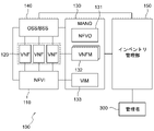
- FIG. 1 is a diagram showing a configuration example of a mobile network including a network management device of this embodiment.
- FIG. 2 is a diagram showing an example of the internal configuration of the network management system.
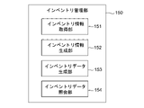
- FIG. 3 is a functional block diagram of an inventory manager.
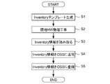
- FIG. 4 is a flow chart showing the flow of registration of inventory information.
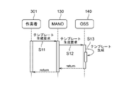
- FIG. 5 is a sequence diagram showing the template generation operation.
- FIG. 6 is an example of a template.
- FIG. 7 is a sequence diagram showing the operation of registering inventory information.
- FIG. 8 is an example of inventory information.
- FIG. 9 is a flow chart showing a procedure for generating inventory data.
- FIG. 10 is a sequence diagram showing an operation of generating inventory data.
- FIG. 11 is an example of data for querying inventory data.
- the network management device generates inventory data of devices (servers) that constitute the virtualization infrastructure in a mobile network built on the virtualization infrastructure, and checks the normality of the generated inventory data.
- the inventory data is setting information necessary for server provisioning (initial setting), including identification information of the accommodation station that accommodates the server, server information including hardware information of the server, and installation position of the server in the accommodation station.
- server provisioning includes processes such as installation of software including an operating system and applications.
- FIG. 1 is a diagram showing a network configuration example of a mobile network 100 including a network management device of this embodiment.
- a terminal capable of mobile communication such as a smartphone and a radio access network (RAN) communicate wirelessly, and the information is relayed through a backhaul network (mobile backhaul: MBH).
- MBH mobile backhaul network
- the mobile network 100 comprises a base station 11 and a plurality of accommodating stations 12-14.
- the accommodation station 12 is an edge data center
- the accommodation station 13 is a regional data center (RDC)
- the accommodation station 14 is a central data center (CDC).
- a backhaul network is configured from the edge data center 12 to the central data center 14 .
- the mobile network 100 in this embodiment may be a virtualized network built on a virtualization infrastructure.
- software is implemented on a general-purpose server from the switchboard of the backbone network to the wireless access function of the base station.
- the base station 11 includes an antenna, a switchboard, a battery, and the like.
- the edge data center 12 is installed near the base stations 11 and is connected to the plurality of base stations 11 by optical fiber cables or the like.
- the edge data center 12 implements RAN-related radio access functions.
- the regional data center 13 is connected to a plurality of edge data centers 12 arranged in the target region. In this regional data center 13, firewall/NAT (Network Address Translation), CDN (Content Distribution Network), and various applications for edge computing are implemented by software.
- the central data center 14 is connected to multiple regional data centers 13 .
- the central data center 14 implements core functions such as EPC (Evolved Packet Core) and IMS (IP Multimedia Subsystem).
- each data center such as the edge data center 12, the regional data center 13, and the central data center 14 is not limited to the number shown in FIG.
- the number of each data center (accommodating station) such as the edge data center 12, the regional data center 13, and the central data center 14 is not limited to the number shown in FIG.
- a plurality of regional data centers 13 and central data centers 14 may be installed.
- FIG. 2 is a diagram showing an example of the internal configuration of a network management system that configures mobile network 100. As shown in FIG. Each component shown in FIG. 2 has a reference point. Lines connecting components shown in FIG. 2 indicate that information can be sent and received from each other.
- NFVI (NFV Infrastructure) 110 is a network function virtualization infrastructure, and includes physical resources, a virtualization layer, and virtualization resources. Physical resources include hardware resources such as computing resources, storage resources, and transmission resources.
- the virtualization layer is a virtualization layer such as a hypervisor for virtualizing physical resources and providing them to VNF (Network Function Virtualization) 120 .
- a virtualized resource is a virtualized infrastructure resource provided to the VNF 120 .
- the NFVI 110 is a virtualized computing and virtualization system in which hardware resources of a physical server (hereinafter also simply referred to as "server") such as computing, storage, and network functions are virtualized by a virtualization layer such as a hypervisor. It is a platform that can be flexibly handled as virtualized hardware resources such as storage and virtualized networks.
- a plurality of servers that make up the NFVI 110 are collectively arranged in data centers (accommodating stations) 12-14.
- the number of servers to be arranged in each data center 12 to 14, the arrangement position, the wiring, etc. are determined in advance according to the type of the data center (accommodating station type).
- the servers installed are connected by an internal network so that information can be transmitted and received between them.
- Data centers are connected by a network, and servers provided in different data centers can transmit and receive information to and from each other via the network.
- the VNF 120 corresponds to an application running on a virtual machine (VM) on the server and implements network functions in software. Although not shown, each VNF 120 may be provided with a management function called EM (Element Manager).
- EM Element Manager
- the NFVI 110 and VNF 120 in FIG. 2 constitute a virtual environment. That is, the virtualization environment is composed of three layers, hardware, virtualization layer, and virtual machine, in order from the bottom.
- a MANO (Management and Orchestration) 130 has a virtual environment management function and an orchestration function.
- the MANO 130 includes an NFVO (NFV-Orchestrator) 131 , a VNFM (VNF-Manager) 132 and a VIM (Virtualized Infrastructure Manager) 133 .
- the NFVO 131 performs orchestration of NFVI resources, life cycle management of network services, and integrated operation management of the entire system.
- the NFVO 131 can perform processing according to instructions from an OSS/BSS (Operation Support System/Business Support System) 140, which will be described later.
- OSS/BSS Operaation Support System/Business Support System
- VNFM 132 performs life cycle management of VNF 120 .
- VNFM 132 may be arranged in MANO 130 as a dedicated VNFM corresponding to each VNF 120 .
- one VNFM 132 may manage the lifecycles of two or more VNFs 120 .
- VNFM 132 may be a generic VNFM that corresponds to VNF 120 from a different vendor.
- the VIM 133 manages and operates resources used by the VNF 120 .
- OSS/BSS 140 is an integrated management system for mobile network 100 .
- OSS is a system (equipment, software, mechanism, etc.) necessary for building and operating a service
- BSS is information used for billing such as usage fees, billing, customer service, etc. It is a system (equipment, software, mechanism, etc.).
- the inventory management unit 150 implements an inventory management function of generating inventory data and checking the normality of the generated inventory data.
- the inventory management unit 150 can generate inventory data, for example, according to an instruction from an administrator 300 who manages inventory data of each device constituting the network.
- This inventory management unit 150 constitutes a network management device according to this embodiment.
- the inventory management unit 150 is not limited to being an external function of the OSS/BSS 140 or the MANO 130 as shown in FIG.
- the inventory management unit 150 may be provided inside the OSS/BSS 140 or may be provided inside the MANO 130 . In this case, the inventory management function of the inventory management unit 150 becomes part of the functions of the OSS/BSS 140 and the MANO 130 .
- FIG. 3 is a functional block diagram of the inventory management unit 150.
- the inventory management unit 150 includes an inventory information acquisition unit 151, an inventory information generation unit 152, an inventory data generation unit 153, and an inventory data inquiry unit 154.
- the inventory information acquisition unit 151 is a basic information acquisition unit that acquires server basic information as inventory information that is information necessary for generating inventory data.
- the inventory information acquisition unit 151 acquires inventory information transferred from a work terminal operated by a worker who has performed physical construction at the site (accommodation station).
- the inventory information (basic server information) acquired by the inventory information acquisition unit 151 includes identification information of the accommodation station, server information including the MAC address that is the identifier of the BMC (Baseboard Management Controller), and location information of the server in the accommodation station. .
- the inventory information generation unit 152 is a related information generation unit that generates server related information, which is other inventory information necessary for generating inventory data, based on the server basic information acquired by the inventory information acquisition unit 151 .
- the inventory information generation unit 152 generates an IP address from at least the BMC MAC address acquired as the server basic information.
- the inventory data generation unit 153 is a setting information generation unit that generates inventory data, which is setting information necessary for server provisioning.
- the inventory data generation unit 153 generates inventory data based on the server basic information acquired by the inventory information acquisition unit 151 and the server-related information including the IP address generated by the inventory information generation unit 152 .
- the inventory data inquiry unit 154 is a data inquiry unit that inquires of the server about the normality of the inventory data generated by the inventory data generation unit 153 . Specifically, the inventory data inquiry unit 154 inquires about the MAC address of the inquiry target server. Then, if the queried MAC address matches the MAC address corresponding to the server to be queried included in the inventory data generated by the inventory data generation unit 153, the inventory data query unit 154 determines that the inventory data is normal. It is determined that In addition, the inventory data inquiry unit 154 inquires about the server specifications of the inquiry target server.
- the inventory data querying unit 154 selects a desired server spec according to the identification information and location information of the accommodating station corresponding to the server to be queried included in the inventory data generated by the inventory data generating unit 153. If the inventory data matches the server specifications, it is determined that the inventory data is normal.
- the inventory data management function will be specifically described below.
- inventory data is generated by using an inventory data template (inventory template) for each accommodation station and embedding inventory information in the template.
- an example of generating inventory data required for provisioning of servers housed in the edge data center 12 will be described.
- an edge data center is called a GC (Group unit Center) to distinguish it from other data centers.
- FIG. 4 is a flow chart showing the flow of registration of inventory information, which is information for generating inventory data.
- the OSS 140 receives a template generation request from an operator and generates a template (inventory template) for each GC.
- This template generation request includes information indicating the GC type specified by the operator.
- the worker who issues the template generation request may be a field worker who actually performs the physical construction of the hardware at the site (GC), or the administrator 300 who manages the inventory data of each device constituting the network. may be
- FIG. 5 is a sequence diagram showing the template generation operation.
- the worker 301 transmits a template generation request to the MANO 130 using the GC type as a key.
- the worker 301 can use a host device of the MANO 130 or the like to send a template generation request.
- the MANO 130 receives a template generation request from the worker 301 and requests the OSS 140 to generate a template.
- step S13 the OSS 14 generates a template.
- An example of the template generated at this time is shown in FIG.
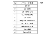
- the template 401 No.
- the GC type designated by the worker 301 as a key for template generation is entered in 5 "GC Type".
- No. Parameter information other than 5 is blank at this time.
- the OSS 140 transmits a return signal indicating completion of template generation as shown in FIG. This return signal is returned to the terminal (device) used by the worker 301 via the MANO 130 .
- the inventory management unit 150 may receive the template generation request and generate the template.
- step S2 the local worker performs physical construction of the hardware (HW).
- the field worker installs a plurality of servers in the rack with the number, arrangement, and wiring according to the GC type.
- step S3 the local worker reads inventory information from the server.
- the field worker scans the image code assigned to the server to read the inventory information embedded in the image code.
- Server information which is part of the server basic information, can be embedded in the image code as inventory information. This server information is information unique to the server, and includes server identification information (server ID), server code, host name, serial number, and MAC address.
- step S4 the field worker transmits inventory information to OSS 140 using the work terminal.
- the field worker sends the server information read from the image code, the GC identification information (accommodating station identification information), and the server basic information linked with the server location information to the OSS 140 as inventory information.
- the GC identification information includes a GC code (GC-specific management code) and GC type.
- the server location information also includes the rack name and rack number of the rack in which the server is installed.
- the OSS 140 registers the inventory information received from the work terminal in a management database or the like.
- FIG. 7 is a sequence diagram showing the operation of registering inventory information to the OSS 140.
- the local worker 302 uses the work terminal 310 to read inventory information in the GC (edge data center) where the physical construction of the server has been performed.
- the local worker 302 designates the identification information (GC code, GC type) of the GC that houses the server and the location information (rack name, rack number) of the server at the work terminal 310. , the inventory information is read.
- the field worker 302 reads inventory information (server information) by scanning an image code given to the server.
- the image code can be a QR code (registered trademark), for example.
- Field worker 302 scans the QR code using work terminal 310 .
- the image code is not limited to a two-dimensional code, and may be any code that can embed server information.
- the image code may be a one-dimensional code such as a bar code or customer bar code.
- the image code may be a multicolor code such as a chameleon code (registered trademark).
- step S22 the work terminal 310 reads inventory information (server information) from the network device (NW device) and the server 500 by the inventory information reading work by the local worker 302.
- step S ⁇ b>23 the work terminal 310 transmits an inventory information registration request to the OSS 140 .
- the work terminal 310 stores, as inventory information, server basic information obtained by linking the server information read from the QR code of the server 500 with the identification information of the GC designated by the field worker 302 and the location information of the server. It is included in the information registration request and transferred to the OSS 140 .
- the local worker 302 operates the work terminal 310 on the GC and transmits an inventory information registration request to the OSS 140
- the field worker 302 should at least read the server information from the QR code at the GC that actually performed the physical construction.
- the task of transmitting the inventory information registration request including the server information read from the QR code from the work terminal 310 to the OSS 140 may be performed from a place other than the GC if the environment allows data transmission to the OSS 140 .
- the inventory information registration request may be transmitted from the work terminal 310 to the OSS 140 via the inventory management unit 150 .
- an inventory information registration request may be sent from the work terminal 310 to the inventory management unit 150 to register inventory information in the inventory management unit 150 .
- the inventory information acquisition unit 151 of the inventory management unit 150 acquires the inventory information included in the inventory information registration request.
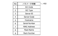
- FIG. 8 is an example of inventory information (basic server information) 402 included in an inventory information registration request transmitted from the work terminal 310 .
- the server basic information 402 includes GC identification information (No. 1, No. 2), server information (No. 3 to No. 7), and server location information (No. 8). , No. 9) and
- the GC identification information (No. 1, No. 2) and the server location information (No. 8, No. 9) are information specified by the local worker 302, and the server information (No. 3 to No. 7) is information read by the local worker 302 from the QR code.
- the OSS 140 registers the server basic information 402 included in the inventory information registration request transmitted from the work terminal 310 as inventory information. Specifically, the OSS 140 registers the template 401 shown in FIG. 6 filled in based on the server basic information 402 shown in FIG. At this time, the OSS 140 reads the template 401 corresponding to the GC type (No. Fill the GC management ID in 1 "GC ID”. This GCID is generated by the OSS 140 . Also, the OSS 140 receives the number of the template 401 . 2 "GC Code", the server basic information 402 No. Fill in 1 "GC Code”.
- Correspondence information (for example, a table) that associates the parameter information of No. 8 with the "GC Code” is prepared in advance, and the OSS 140 refers to the correspondence information based on the "GC Code" to determine the number of the template 401. . 3, No. 4, No. 6 to No. 8 parameter information may be filled.
- the correspondence information may be stored and managed by the OSS 140, or may be acquired from the outside by the OSS 140 and temporarily stored.
- the template 401 No. 3 is the Japanese notation of the GC name; 4 is filled with the English notation of the GC name.
- the template 401 No. 6 is filled with regional information including, for example, the area where the GC is installed (West Japan/East Japan), prefecture, municipality, address, latitude, longitude, and the like.
- the template 401 No. 7 is filled with information for calculating the IP address. For example, when an IPv6 address is used as the IP address, the template 401 No.
- the information embedded in 7 includes information for determining the prefix that constitutes the IPv6 address.
- the template 401 No. 8 is filled with central data center information to which the GC is connected.
- the central data center information includes, for example, the central data center name, DNS server IP address, and the like.
- the template 401 No. 9, the No. of the server basic information 402; 8 and no. 9 parameter information is filled.
- the template 401 No. 10, the No. of the server basic information 402; 3 to No. 7 parameter information is filled.
- the inventory information including the server basic information 402 designated by the field worker 302 or read from the QR code and the information derived from the server basic information 402 can be registered in the OSS 140. can.
- the OSS 140 After registering the inventory information, the OSS 140 returns a return signal indicating completion of the registration of the inventory information to the work terminal 310 .
- the field worker 302 can confirm the completion of registration of the inventory information by confirming the return signal returned to the work terminal 310 .
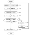
- FIG. 9 is a flow chart showing a procedure for generating inventory data.
- the OSS 140 acquires an inventory data generation request transmitted from the administrator 300 .
- the OSS 140 generates other inventory information necessary for generating inventory data based on the inventory information registered by the processing shown in FIG.
- the process of generating inventory information in step S32 includes, for example, a process of generating an IP address from a MAC address.
- step S33 the OSS 140 generates inventory data. Specifically, the OSS 140 adds the inventory information generated in step S32 to the inventory information registered by the process of FIG. 4 to generate inventory data. In step S34, the OSS 140 inquires of the server about the normality of the inventory data generated in step S33.
- FIG. 10 is a sequence diagram showing an inventory data generation operation and an inquiry operation.
- the administrator 300 transmits an inventory data generation request to the OSS 140 .
- the inventory data generation request is transmitted from the inventory management unit 150 to the OSS 140 via the MANO 130 (steps S42, S43).
- the inventory data generation request includes the GC ID or GC code.
- OSS 140 transmits an IP address generation request to IP address management unit 400 .
- the OSS 140 reads the inventory information (the template 401 in which the basic server information 402 is embedded) registered by the process of FIG. 4 based on the GC ID or GC code included in the inventory data generation request, Among the information contained in the inventory information, the information necessary for calculating the IP address is included in the IP address generation request and transmitted to the IP address management unit 400 .
- the information included in the IP address generation request includes the MAC address included in the IP address information (No. 7) and server information (No. 10) of the template 401 .
- the IP address management unit 400 generates an IP address based on information received from the OSS 140 and transmits it to the OSS 140 .
- the OSS 140 Upon receiving the IP address from the IP address management unit 400, the OSS 140 adds the IP address to the inventory information registered by the process of FIG. 4 in step S45. Inventory data is thus generated. That is, the inventory data is generated by embedding the server basic information 402 and the server-related information generated from the server basic information 402 in the template 401 for each GC.
- the server-related information includes inventory information derived from the server basic information 402 (eg, “Regional information” in FIG. 6, etc.) and inventory information calculated from the server basic information 402 (eg, IP address, etc.).
- the server-related information is not limited to the above.
- a configuration file for software operating on the server may be generated and included in the inventory data as server-related information.
- parameters required for configuration management of various installations can be included in the inventory data as server-related information.
- the OSS 140 transmits an inventory data confirmation request to the server to be queried, and inquires of the server about the normality of the inventory data generated in step S45. Specifically, the OSS 140 transmits the server ID and MAC address included in the inventory data to the NFVI 110 and checks whether they match the actual association between the server ID and the MAC address. At this time, if the correspondence between the server ID and the MAC address transmitted to the NFVI 110 and the correspondence between the server ID and the MAC address obtained from the NFVI 110 match, the OSS 140 sets the correspondence between the server ID and the MAC address. It can be determined that the attachment is correct, that is, the inventory data is normal.
- the OSS 140 may inquire about the server specifications of the server to be queried, and inquire of the server about the normality of the inventory data generated in step S45.
- the NFVI 110 returns to the OSS 140 the server specification information of the server to be inquired based on the server ID and MAC address received from the OSS 140 .
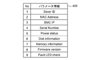
- FIG. 11 shows an example of server specification information transmitted from the NFVI 110 at this time.
- the NFVI 110 includes the BMC IP address (BMC IP), serial number (Serial Number), power ON/OFF status (Power status), disk capacity (Disk information), and memory capacity (Memory information).
- BMC IP BMC IP address
- Serial Number Serial Number
- Power ON/OFF status Power status
- disk capacity disk information
- Memory capacity Memory information
- firmware version, and fault detection signal are linked with the server ID and MAC address received from the OSS 140 as keys for the inventory data confirmation request, and sent to the OSS 140 as server spec information 403 .
- the No. of the server spec information 403 is used. 4 to No.
- the parameter information of 9 is information that can be obtained by accessing the inquiry target server using the IP address of the BMC.
- the specifications expected for each server are determined in advance according to the GC type. Therefore, the OSS 140 collates the server specs acquired from the NFVI 110 with the desired server specs according to the identification information (GC type, etc.) of the GC that houses the server to be queried and the location information (rack information) of the server, It is determined whether or not the two match. Then, if both match, it can be determined that the server spec is as expected, that is, the inventory data is normal and the server spec is normal. For example, if the memory is not physically correctly inserted, as a result of checking the server specification information, it is determined that the memory capacity has not reached the desired capacity. Therefore, anomalies in server specifications can be appropriately detected.
- the identification information GC type, etc.
- rack information location information
- step S35 the OSS 140 determines whether an inventory data abnormality or a server specification abnormality is detected as a result of the data inquiry in step S34. Then, when an abnormality in the inventory data or an abnormality in the server specifications is detected, the process proceeds to step S36 to analyze the cause of the abnormality. For example, when an abnormality in the inventory data is detected, it is verified whether the wiring of the server is correct, whether there was any problem in the inventory information reading work and the registration work performed by the field worker 302, and so on. Also, when an abnormality in the server specifications is detected, a component failure, connection abnormality, or the like is verified.
- step S37 according to the analysis result in step S36, correction of the wiring, replacement of parts, replacement of the server, etc. are performed, and the process returns to step S31.
- the OSS 140 confirms that the inventory data and server specifications are normal in step S35, the OSS 140 proceeds to step S38 and determines that preparations for starting the server construction work have been completed.
- OSS 140 may perform server provisioning.
- the administrator 300 may instruct the OSS 140 to start the provisioning when preparations for starting the server construction work are complete.
- the inventory management unit 150 may perform the above processing.
- the inventory information generation unit 152 of the inventory management unit 150 performs the processing of step S32
- the inventory data generation unit 153 performs the processing of step S33
- the inventory data query unit 154 performs the processing of steps S34 and S35.
- GC edge data center
- inventory data can be registered and managed in the same manner for servers housed in the central data center and regional data centers.
- inventory data may be registered and managed for each POD. Therefore, in that case, "GC” in the above explanation should be read as "POD”.
- GC in the above explanation should be read as "RDC”.
- RDC RDC
- the template 401 for each GC shown in FIG. 6 is a template for each POD or each RDC.
- the inventory management unit 150 which is a network management device according to the present embodiment, stores identification information of an accommodating station that accommodates a server, server information including the MAC address of the BMC of the server, and the installation position of the server in the accommodating station.
- Server basic information 402 including location information to be indicated is acquired, and server-related information including the IP address of the server is generated based on the acquired server basic information 402 .
- the inventory management unit 150 generates setting information (inventory data) necessary for server provisioning based on the acquired server basic information 402 and the generated server-related information including the IP address, and query the server for the health of the inventory data.
- Telecom networks are large-scale, and there are a large number of servers that constitute the network and accommodation stations that accommodate the servers. Manually registering the inventory data required for provisioning of each of these many servers is a very time-consuming task and may cause human error.
- the inventory data required for server provisioning is generated based on the server basic information 402, and the server is inquired about the normality of the generated inventory data, so the inventory data can be registered and managed easily and accurately. can do.
- the server information can be information read from the server by the field worker 302 who actually installed the server at the accommodation station.
- the server location information can be information about the installation location of the server specified by the field worker 302 .
- the server basic information 402 can be data in which the local worker 302 links the server information with the identification information of the accommodation station and the location information of the server.
- the on-site worker 302 is a person who performs physical construction of the server, and is a person who can guarantee which server is installed at which location in which accommodation station. Therefore, by linking the server information read from the server by the local worker 302 as described above with the identification information of the accommodation station and the location information of the server specified by the local worker 302, the appropriate basic server information 402 can be obtained. be done.
- server information such as MAC address, server ID, server code, host name, and serial number is embedded in the QR code and given to the server, and the local knowledge worker 302 reads the server information from the QR code, so that the information can be does not have to manually enter or manage server information. Therefore, it is possible to appropriately suppress the occurrence of human errors due to human intervention in registration and management. As a result, it is possible to reduce the time and manpower required for error handling.
- an inventory data template 401 is generated for each accommodation station, and server basic information 402 and server-related information generated from the server basic information 402 are embedded in the generated template 401. , may generate inventory data. In this way, by using an inventory data template, it is possible to easily and appropriately generate inventory data simply by acquiring the minimum information necessary for generating inventory data.
- the normality of the inventory data can be confirmed by inquiring the MAC address of the server. Therefore, for example, if the field worker 402 makes a mistake in the wiring of the server, this can be detected appropriately and dealt with.
- the server When the physical work is completed and the server is connected to the network, it is possible to access the server and obtain the serial number and hardware information of the server via the network. Therefore, it is conceivable to realize automatic provisioning that automatically performs server information acquisition, inventory data generation, and execution of provisioning.
- this server is installed at this position in this rack of this accommodation station, the server information of this server will be obtained remotely, so if the wiring of the server is incorrect, In some cases, provisioning is performed without realizing the mistake.
- the server can be queried for server specs to see if they match the server specs expected of the server. As a result, even if there is no mistake in the wiring of the server, for example, if the memory is not properly inserted, this can be detected appropriately and dealt with.
- setting information (inventory data) required for provisioning of devices that make up a large-scale network can be registered easily and with high accuracy.
- the network management device may be implemented in any general-purpose server that constitutes the backhaul network, core network, or the like of the mobile network 100 .
- the network management device may be implemented in a dedicated server.
- the network management device may be implemented on a single or multiple computers.
- the network management device includes a CPU, ROM, RAM, HDD, input unit (keyboard, pointing device, etc.), display unit (monitor, etc.), communication I/F, etc. can be provided.
- the network management device includes a CPU, ROM, RAM, HDD, input unit (keyboard, pointing device, etc.), display unit (monitor, etc.), communication I/F, etc. can be provided.
- the network management device includes a CPU, ROM, RAM, HDD, input unit (keyboard, pointing device, etc.), display unit (monitor, etc.), communication I/F, etc. can be provided.
- the network management device includes a CPU, ROM, RAM, HDD, input unit (keyboard, pointing device
- Base station 12 Edge data center 13
- Regional data center 14 Central data center 100
- Mobile network 110 NFVI 120
- VNF 130 MANO 131
- NFVO 132 VNFM 133
- VIM 140 OSS/BSS 150
- Inventory management unit 151 Inventory information acquisition unit 152
- Inventory information generation unit 153 Inventory data generation unit 154
- Inventory data inquiry unit 401 Inventory data template 402 ... server basic information, 403 ... server spec information
Landscapes
- Engineering & Computer Science (AREA)
- Computer Networks & Wireless Communication (AREA)
- Signal Processing (AREA)
- Software Systems (AREA)
- Theoretical Computer Science (AREA)
- Physics & Mathematics (AREA)
- General Engineering & Computer Science (AREA)
- General Physics & Mathematics (AREA)
- Data Exchanges In Wide-Area Networks (AREA)
Abstract
大規模ネットワークを構成する機器のプロビジョニングに必要な設定情報を容易かつ高精度に登録する。 ネットワーク管理装置は、ネットワークを構成するサーバを収容する収容局の識別情報と、サーバのBMC(Baseboard Management Controller)の識別子を含むサーバ情報と、収容局におけるサーバの実装位置を示す位置情報と、を含むサーバ基本情報を取得する基本情報取得部と、基本情報取得部により取得されたサーバ基本情報に基づいて、少なくともサーバのIPアドレスを含むサーバ関連情報を生成する関連情報生成部と、基本情報取得部により取得されたサーバ基本情報と、関連情報生成部により生成されたサーバ関連情報と、に基づいて、サーバのプロビジョニングに必要な設定情報を生成する設定情報生成部と、設定情報生成部により生成された設定情報の正常性をサーバに照会するデータ照会部と、を備える。
Description
本発明は、ネットワーク管理装置、ネットワーク管理方法およびプログラムに関し、特に、モバイルネットワークを構成する機器のプロビジョニングを行うための技術に関する。
汎用サーバの性能向上、ネットワーク基盤の充実を背景として、サーバなどの物理リソース上に仮想化されたコンピューティングリソースをオンデマンドで使うクラウドコンピューティング(以下、「クラウド」という。)が広く普及している。また、ネットワーク機能を仮想化し、クラウド上で提供するNFV(Network Function Virtualization)が知られている。NFVとは、仮想化技術およびクラウド技術を用いて、これまで専用ハードウェア上で動いていた様々なネットワークサービスのハードウェアとソフトウェアとを分離し、ソフトウェアを仮想化された基盤上で動かす技術である。これによって運用の高度化やコスト削減が期待される。
そして、近年、モバイルネットワークにおいても仮想化が進められている。
ETSI(European Telecommunications Standards Institute) NFVでは、NFVのアーキテクチャが定義されている(例えば、特許文献1参照)。
そして、近年、モバイルネットワークにおいても仮想化が進められている。
ETSI(European Telecommunications Standards Institute) NFVでは、NFVのアーキテクチャが定義されている(例えば、特許文献1参照)。
近年のモバイルネットワークは仮想化基盤で構築されており、柔軟性や拡張性に優れている。
しかしながら、例えばサーバを収容するデータセンタ(収容局)を新たに構築する場合には、当該データセンタにおいて人がサーバの敷設工事を行うことが前提である。また、サーバのプロビジョニング(初期設定)を行うためには、サーバのハードウェア情報など、プロビジョニングに必要な設定情報であるインベントリデータ(Inventoryデータ)を事前に登録する必要があるが、従来、当該データの登録は手動で行われてきた。
しかしながら、例えばサーバを収容するデータセンタ(収容局)を新たに構築する場合には、当該データセンタにおいて人がサーバの敷設工事を行うことが前提である。また、サーバのプロビジョニング(初期設定)を行うためには、サーバのハードウェア情報など、プロビジョニングに必要な設定情報であるインベントリデータ(Inventoryデータ)を事前に登録する必要があるが、従来、当該データの登録は手動で行われてきた。
モバイルネットワークは大規模ネットワークであり、プロビジョニングの対象となるサーバも多数存在することから、手作業によるインベントリデータの登録は非常に手間のかかる作業であった。また、上記のように人が介在するプロセスでは、ヒューマンエラーが不可避的に発生し、これに起因するネットワーク障害を招来し得る。
そこで、本発明は、大規模ネットワークを構成する機器のプロビジョニングに必要な設定情報を容易かつ高精度に登録することが可能なネットワーク管理装置、ネットワーク管理方法およびプログラムを提供することを課題としている。
上記課題を解決するために、本発明に係るネットワーク管理装置の一態様は、ネットワークを構成するサーバを収容する収容局の識別情報と、前記サーバのBMC(Baseboard Management Controller)の識別子を含むサーバ情報と、前記収容局における前記サーバの設置位置を示す位置情報と、を含むサーバ基本情報を取得する基本情報取得部と、前記基本情報取得部により取得されたサーバ基本情報に基づいて、少なくとも前記サーバのIPアドレスを含むサーバ関連情報を生成する関連情報生成部と、前記基本情報取得部により取得されたサーバ基本情報と、前記関連情報生成部により生成されたサーバ関連情報とに基づいて、前記サーバのプロビジョニングに必要な設定情報を生成する設定情報生成部と、前記設定情報生成部により生成された設定情報の正常性を前記サーバに照会するデータ照会部と、を備える。
前記BMCの識別子は、前記BMCのMACアドレスであってよい。
前記基本情報取得部は、前記サーバを前記収容局に設置した作業者が前記サーバに付与された画像コードから読み取った前記サーバ情報を取得してよい。
前記サーバ情報は、前記BMCの識別子と、サーバID、サーバコード、ホスト名およびシリアルナンバーの少なくとも1つと、を含んでよい。
前記基本情報取得部は、前記サーバを前記収容局に設置した作業者が前記サーバに付与された画像コードから読み取った前記サーバ情報を取得してよい。
前記サーバ情報は、前記BMCの識別子と、サーバID、サーバコード、ホスト名およびシリアルナンバーの少なくとも1つと、を含んでよい。
前記基本情報取得部は、前記サーバを前記収容局に設置した作業者が指定した前記位置情報を取得してよい。
前記位置情報は、前記サーバが設置されたラックのラック名およびラック番号の少なくとも一方を含んでよい。
前記位置情報は、前記サーバが設置されたラックのラック名およびラック番号の少なくとも一方を含んでよい。
前記ネットワーク管理装置は、前記収容局ごとの前記設定情報のテンプレートを生成するテンプレート生成部をさらに備え、前記設定情報生成部は、前記基本情報取得部により取得された前記収容局の識別情報に基づいて前記テンプレート生成部により生成されたテンプレートに、前記基本情報取得部により取得されたサーバ基本情報と前記関連情報生成部により生成されたサーバ関連情報とを埋め込むことで、前記設定情報を生成してよい。
前記BMCの識別子は、前記BMCのMACアドレスであり、前記データ照会部は、照会対象の前記サーバの前記MACアドレスを照会し、照会された前記MACアドレスが、前記設定情報生成部により生成された設定情報に含まれる前記照会対象のサーバに対応する前記MACアドレスと一致する場合に、前記設定情報が正常であると判定してよい。
前記データ照会部は、照会対象の前記サーバのサーバスペックを照会し、照会された前記サーバスペックが、前記設定情報生成部により生成された設定情報に含まれる前記照会対象のサーバに対応する前記収容局の識別情報および前記位置情報に応じた所望のサーバスペックと一致する場合に、前記設定情報が正常であると判定してよい。
前記ネットワーク管理装置は、前記データ照会部により前記設定情報の正常性が確認された場合、前記設定情報生成部により生成された設定情報を用いて前記サーバのプロビジョニングを実行するプロビジョニング実行部をさらに備えてよい。
前記基本情報取得部は、仮想マシンが動作するサーバの前記サーバ基本情報を取得してよい。
また、本発明に係るネットワーク管理方法の一態様は、ネットワーク管理装置が実行するネットワーク管理方法であって、ネットワークを構成するサーバを収容する収容局の識別情報と、前記サーバのBMC(Baseboard Management Controller)の識別子を含むサーバ情報と、前記収容局における前記サーバの設置位置を示す位置情報と、を含むサーバ基本情報を取得するステップと、取得された前記サーバ基本情報に基づいて、少なくとも前記サーバのIPアドレスを含むサーバ関連情報を生成するステップと、取得された前記サーバ基本情報と、生成された前記サーバ関連情報とに基づいて、前記サーバのプロビジョニングに必要な設定情報を生成するステップと、生成された前記設定情報の正常性を前記サーバに照会するステップと、を含む。
さらに、本発明に係るネットワーク管理プログラムの一態様は、ネットワーク管理処理をコンピュータに実行させるためのネットワーク管理プログラムであって、該プログラムは、前記コンピュータに、ネットワークを構成するサーバを収容する収容局の識別情報と、前記サーバのBMC(Baseboard Management Controller)の識別子を含むサーバ情報と、前記収容局における前記サーバの設置位置を示す位置情報と、を含むサーバ基本情報を取得する取得処理と、前記取得処理により取得されたサーバ基本情報に基づいて、少なくとも前記サーバのIPアドレスを含むサーバ関連情報を生成する第1の生成処理と、前記取得処理により取得されたサーバ基本情報と、前記第1の生成処理により生成されたサーバ関連情報とに基づいて、前記サーバのプロビジョニングに必要な設定情報を生成する第2の生成処理と、前記第2の生成処理により生成された設定情報の正常性を前記サーバに照会する照会処理と、を含む処理を実行させるためのものである。
本発明の一つの態様によれば、大規模ネットワークを構成する機器のプロビジョニングに必要な設定情報を容易かつ高精度に登録することができる。
上記した本発明の目的、態様及び効果並びに上記されなかった本発明の目的、態様及び効果は、当業者であれば添付図面及び請求の範囲の記載を参照することにより下記の発明を実施するための形態から理解できるであろう。
上記した本発明の目的、態様及び効果並びに上記されなかった本発明の目的、態様及び効果は、当業者であれば添付図面及び請求の範囲の記載を参照することにより下記の発明を実施するための形態から理解できるであろう。
以下、添付図面を参照して、本発明を実施するための実施形態について詳細に説明する。以下に開示される構成要素のうち、同一機能を有するものには同一の符号を付し、その説明を省略する。なお、以下に開示される実施形態は、本発明の実現手段としての一例であり、本発明が適用される装置の構成や各種条件によって適宜修正または変更されるべきものであり、本発明は以下の実施形態に限定されるものではない。また、本実施形態で説明されている特徴の組み合わせの全てが本発明の解決手段に必須のものとは限らない。
以下、本実施形態に係るネットワーク管理装置が、仮想化基盤で構築されたモバイルネットワークにおいて、当該仮想化基盤を構成する機器(サーバ)のインベントリデータを生成し、生成したインベントリデータの正常性を確認して管理するインベントリ管理機能を備える場合について説明する。
ここで、インベントリデータとは、サーバのプロビジョニング(初期設定)に必要な設定情報であり、サーバを収容する収容局の識別情報、サーバのハードウェア情報を含むサーバ情報、収容局におけるサーバの設置位置を示す位置情報といったサーバ基本情報を含む。サーバのプロビジョニングには、オペレーティングシステムやアプリケーションを含むソフトウェアのインストール等の処理が含まれる。
ここで、インベントリデータとは、サーバのプロビジョニング(初期設定)に必要な設定情報であり、サーバを収容する収容局の識別情報、サーバのハードウェア情報を含むサーバ情報、収容局におけるサーバの設置位置を示す位置情報といったサーバ基本情報を含む。サーバのプロビジョニングには、オペレーティングシステムやアプリケーションを含むソフトウェアのインストール等の処理が含まれる。
図1は、本実施形態のネットワーク管理装置を含むモバイルネットワーク100のネットワーク構成例を示す図である。
図1に示すモバイルネットワーク100においては、スマートフォンなどのモバイル通信可能な端末と無線アクセスネットワーク(Radio Access Network:RAN)とが無線通信し、その情報をバックホールネットワーク(モバイルバックホール:MBH)を中継してコアネットワークに送って処理することで、インターネット200に接続したり、他社のネットワークと接続して音声通話をしたりすることができる。
図1に示すモバイルネットワーク100においては、スマートフォンなどのモバイル通信可能な端末と無線アクセスネットワーク(Radio Access Network:RAN)とが無線通信し、その情報をバックホールネットワーク(モバイルバックホール:MBH)を中継してコアネットワークに送って処理することで、インターネット200に接続したり、他社のネットワークと接続して音声通話をしたりすることができる。
具体的には、モバイルネットワーク100は、基地局11と、複数の収容局12~14と、を備えて構成される。ここで、収容局12はエッジデータセンタ、収容局13は地域データセンタ(Regional Data Center:RDC)、収容局14は中央データセンタ(Central Data Center:CDC)である。エッジデータセンタ12から中央データセンタ14までの間でバックホールネットワークが構成される。
本実施形態におけるモバイルネットワーク100は、仮想化基盤で構築された仮想化ネットワークであってよい。このモバイルネットワーク100では、汎用的なサーバ上に、基幹網の交換機から基地局の無線アクセス機能までをソフトウェアで実現している。
本実施形態におけるモバイルネットワーク100は、仮想化基盤で構築された仮想化ネットワークであってよい。このモバイルネットワーク100では、汎用的なサーバ上に、基幹網の交換機から基地局の無線アクセス機能までをソフトウェアで実現している。
基地局11は、アンテナや配電盤、バッテリー等を備える。
エッジデータセンタ12は、基地局11の近くに設置され、複数の基地局11とそれぞれ光ファイバーケーブル等で接続されている。エッジデータセンタ12では、RAN関連の無線アクセス機能を実現する。
地域データセンタ13は、対象地域に配置される複数のエッジデータセンタ12と接続されている。この地域データセンタ13では、ファイアウォール/NAT(Network Address Translation)、CDN(Content Distribution Network)や、エッジコンピューティングのためのさまざまなアプリケーションをソフトウェアにより実現する。
中央データセンタ14は、複数の地域データセンタ13と接続されている。この中央データセンタ14では、EPC(Evolved Packet Core)やIMS(IP Multimedia Subsystem)などのコア機能を実現する。
エッジデータセンタ12は、基地局11の近くに設置され、複数の基地局11とそれぞれ光ファイバーケーブル等で接続されている。エッジデータセンタ12では、RAN関連の無線アクセス機能を実現する。
地域データセンタ13は、対象地域に配置される複数のエッジデータセンタ12と接続されている。この地域データセンタ13では、ファイアウォール/NAT(Network Address Translation)、CDN(Content Distribution Network)や、エッジコンピューティングのためのさまざまなアプリケーションをソフトウェアにより実現する。
中央データセンタ14は、複数の地域データセンタ13と接続されている。この中央データセンタ14では、EPC(Evolved Packet Core)やIMS(IP Multimedia Subsystem)などのコア機能を実現する。
なお、エッジデータセンタ12、地域データセンタ13、中央データセンタ14といった各データセンタ(収容局)の数は、図1に示す数に限定されない。例えば図1では、地域データセンタ13および中央データセンタ14を1つずつしか図示していないが、地域データセンタ13および中央データセンタ14はそれぞれ複数設置されていてもよい。
図2は、モバイルネットワーク100を構成するネットワーク管理システムの内部構成の一例を示す図である。
この図2に示す構成要素は、それぞれ参照点を有している。図2に示す構成要素間を結ぶ線は、互いに情報の送受信が可能であることを示している。
NFVI(NFV Infrastructure)110は、ネットワーク機能仮想化基盤であり、物理資源、仮想化層、仮想化資源を含んで構成される。物理資源には、計算資源、記憶資源、伝送資源といったハードウェアリソースが含まれる。仮想化層は、物理資源を仮想化してVNF(Network Function Virtualization)120に提供するためのハイパーバイザー等の仮想化レイヤである。仮想化資源は、VNF120に提供される仮想化されたインフラ資源である。
この図2に示す構成要素は、それぞれ参照点を有している。図2に示す構成要素間を結ぶ線は、互いに情報の送受信が可能であることを示している。
NFVI(NFV Infrastructure)110は、ネットワーク機能仮想化基盤であり、物理資源、仮想化層、仮想化資源を含んで構成される。物理資源には、計算資源、記憶資源、伝送資源といったハードウェアリソースが含まれる。仮想化層は、物理資源を仮想化してVNF(Network Function Virtualization)120に提供するためのハイパーバイザー等の仮想化レイヤである。仮想化資源は、VNF120に提供される仮想化されたインフラ資源である。
即ち、NFVI110は、コンピューティング、ストレージ、ネットワーク機能といった物理サーバ(以下、単に「サーバ」ともいう。)のハードウェアリソースを、ハイパーバイザー等の仮想化レイヤで仮想化した仮想化コンピューティング、仮想化ストレージ、仮想化ネットワークといった仮想化ハードウェアリソースとして柔軟に扱えるようにした基盤である。
NFVI110を構成するサーバは、複数まとめてデータセンタ(収容局)12~14に配置される。各データセンタ12~14に配置されるサーバの台数や配置位置、配線等は、データセンタのタイプ(収容局タイプ)によって予め定められている。各データセンタ12~14では、配置されたサーバが内部のネットワークによって接続されており、互いに情報の送受信を行うことができるようになっている。また、データセンタ間はネットワークで接続されており、異なるデータセンタに設けられたサーバは、当該ネットワークを介して互いに情報の送受信を行うことができるようになっている。
VNF120は、サーバ上の仮想マシン(Virtual Machine:VM)で動作するアプリケーションに対応し、ネットワーク機能をソフトウェア的に実現する。なお、特に図示しないが、VNF120ごとにEM(Element Manager)という管理機能が設けられていてもよい。
図2におけるNFVI110とVNF120とで仮想化環境を構成している。つまり、仮想化環境は、下層から順に、ハードウェア、仮想化レイヤ、仮想マシンの3レイヤで構成される。
図2におけるNFVI110とVNF120とで仮想化環境を構成している。つまり、仮想化環境は、下層から順に、ハードウェア、仮想化レイヤ、仮想マシンの3レイヤで構成される。
MANO(Management and Orchestration)130は、仮想化環境の管理機能とオーケストレーション機能とを有する。MANO130は、NFVO(NFV-Orchestrator)131、VNFM(VNF-Manager)132、VIM(Virtualized Infrastructure Manager)133を備える。
NFVO131は、NFVIリソースのオーケストレーションや、ネットワークサービスのライフサイクル管理を行い、システム全体の統合的な運用管理を行う。このNFVO131は、後述するOSS/BSS(Operation Support System/Business Support System)140からの指示に応じた処理を行うことができる。
NFVO131は、NFVIリソースのオーケストレーションや、ネットワークサービスのライフサイクル管理を行い、システム全体の統合的な運用管理を行う。このNFVO131は、後述するOSS/BSS(Operation Support System/Business Support System)140からの指示に応じた処理を行うことができる。
VNFM132は、VNF120のライフサイクル管理を行う。なお、VNFM132は、VNF120毎に、それぞれ対応する専用VNFMとしてMANO130に配置されていてもよい。または、1つのVNFM132が、2以上のVNF120のライフサイクルを管理してもよい。この場合、VNFM132は、異なるベンダから提供されるVNF120に対応する汎用VNFMであってもよい。
VIM133は、VNF120が使用するリソースの運用管理を行う。
VIM133は、VNF120が使用するリソースの運用管理を行う。
OSS/BSS140は、モバイルネットワーク100の統合管理システムである。
ここで、OSSは、サービスを構築し、運営していくために必要なシステム(機器やソフトウェア、仕組みなど)であり、BSSは、利用料などの課金、請求、顧客対応などのために用いる情報システム(機器やソフトウェア、仕組みなど)である。
ここで、OSSは、サービスを構築し、運営していくために必要なシステム(機器やソフトウェア、仕組みなど)であり、BSSは、利用料などの課金、請求、顧客対応などのために用いる情報システム(機器やソフトウェア、仕組みなど)である。
インベントリ管理部150は、インベントリデータの生成および生成されたインベントリデータの正常性の確認を行うインベントリ管理機能を実現する。インベントリ管理部150は、例えばネットワークを構成する各機器のインベントリデータを管理する管理者300による指示に従って、インベントリデータの生成等を行うことができる。このインベントリ管理部150が本実施形態に係るネットワーク管理装置を構成している。
なお、インベントリ管理部150は、図2に示すようにOSS/BSS140やMANO130の外部機能である場合に限定されない。インベントリ管理部150は、OSS/BSS140の内部に設けられていてもよいし、MANO130の内部に設けられていてもよい。この場合、インベントリ管理部150が有するインベントリ管理機能は、OSS/BSS140やMANO130の機能の一部となる。
なお、インベントリ管理部150は、図2に示すようにOSS/BSS140やMANO130の外部機能である場合に限定されない。インベントリ管理部150は、OSS/BSS140の内部に設けられていてもよいし、MANO130の内部に設けられていてもよい。この場合、インベントリ管理部150が有するインベントリ管理機能は、OSS/BSS140やMANO130の機能の一部となる。
図3は、インベントリ管理部150の機能ブロック図である。
この図3に示すように、インベントリ管理部150は、インベントリ情報取得部151と、インベントリ情報生成部152と、インベントリデータ生成部153と、インベントリデータ照会部154と、を備える。
インベントリ情報取得部151は、インベントリデータの生成に必要な情報であるインベントリ情報としてサーバ基本情報を取得する基本情報取得部である。本実施形態では、インベントリ情報取得部151は、現地(収容局)で物理工事を行った作業員が操作する作業端末から転送されるインベントリ情報を取得する。インベントリ情報取得部151が取得するインベントリ情報(サーバ基本情報)は、収容局の識別情報、BMC(Baseboard Management Controller)の識別子であるMACアドレスを含むサーバ情報、および収容局におけるサーバの位置情報を含む。
この図3に示すように、インベントリ管理部150は、インベントリ情報取得部151と、インベントリ情報生成部152と、インベントリデータ生成部153と、インベントリデータ照会部154と、を備える。
インベントリ情報取得部151は、インベントリデータの生成に必要な情報であるインベントリ情報としてサーバ基本情報を取得する基本情報取得部である。本実施形態では、インベントリ情報取得部151は、現地(収容局)で物理工事を行った作業員が操作する作業端末から転送されるインベントリ情報を取得する。インベントリ情報取得部151が取得するインベントリ情報(サーバ基本情報)は、収容局の識別情報、BMC(Baseboard Management Controller)の識別子であるMACアドレスを含むサーバ情報、および収容局におけるサーバの位置情報を含む。
インベントリ情報生成部152は、インベントリ情報取得部151により取得されたサーバ基本情報に基づいて、インベントリデータの生成に必要な他のインベントリ情報であるサーバ関連情報を生成する関連情報生成部である。インベントリ情報生成部152は、少なくともサーバ基本情報として取得したBMCのMACアドレスからIPアドレスを生成する。
インベントリデータ生成部153は、サーバのプロビジョニングに必要な設定情報であるインベントリデータを生成する設定情報生成部である。インベントリデータ生成部153は、インベントリ情報取得部151により取得されたサーバ基本情報と、インベントリ情報生成部152により生成されたIPアドレスを含むサーバ関連情報とに基づいて、インベントリデータを生成する。
インベントリデータ生成部153は、サーバのプロビジョニングに必要な設定情報であるインベントリデータを生成する設定情報生成部である。インベントリデータ生成部153は、インベントリ情報取得部151により取得されたサーバ基本情報と、インベントリ情報生成部152により生成されたIPアドレスを含むサーバ関連情報とに基づいて、インベントリデータを生成する。
インベントリデータ照会部154は、インベントリデータ生成部153により生成されたインベントリデータの正常性をサーバに照会するデータ照会部である。
具体的には、インベントリデータ照会部154は、照会対象のサーバのMACアドレスを照会する。そして、インベントリデータ照会部154は、照会されたMACアドレスが、インベントリデータ生成部153により生成されたインベントリデータに含まれる照会対象のサーバに対応するMACアドレスと一致する場合に、当該インベントリデータが正常であると判定する。
また、インベントリデータ照会部154は、照会対象のサーバのサーバスペックを照会する。そして、インベントリデータ照会部154は、照会されたサーバスペックが、インベントリデータ生成部153により生成されたインベントリデータに含まれる照会対象のサーバに対応する収容局の識別情報および位置情報に応じた所望のサーバスペックと一致する場合に、当該インベントリデータが正常であると判定する。
具体的には、インベントリデータ照会部154は、照会対象のサーバのMACアドレスを照会する。そして、インベントリデータ照会部154は、照会されたMACアドレスが、インベントリデータ生成部153により生成されたインベントリデータに含まれる照会対象のサーバに対応するMACアドレスと一致する場合に、当該インベントリデータが正常であると判定する。
また、インベントリデータ照会部154は、照会対象のサーバのサーバスペックを照会する。そして、インベントリデータ照会部154は、照会されたサーバスペックが、インベントリデータ生成部153により生成されたインベントリデータに含まれる照会対象のサーバに対応する収容局の識別情報および位置情報に応じた所望のサーバスペックと一致する場合に、当該インベントリデータが正常であると判定する。
以下、インベントリデータ管理機能について具体的に説明する。
本実施形態では、収容局ごとのインベントリデータのテンプレート(Inventoryテンプレート)を用い、当該テンプレートにインベントリ情報を埋め込むことでインベントリデータを生成する場合について説明する。
また、以下の説明では、エッジデータセンタ12に収容するサーバのプロビジョニングに必要なインベントリデータを生成する例について説明する。なお、以下の説明では、エッジデータセンタを他のデータセンタと区別するためにGC(Group unit Center)と呼ぶ。
本実施形態では、収容局ごとのインベントリデータのテンプレート(Inventoryテンプレート)を用い、当該テンプレートにインベントリ情報を埋め込むことでインベントリデータを生成する場合について説明する。
また、以下の説明では、エッジデータセンタ12に収容するサーバのプロビジョニングに必要なインベントリデータを生成する例について説明する。なお、以下の説明では、エッジデータセンタを他のデータセンタと区別するためにGC(Group unit Center)と呼ぶ。
図4は、インベントリデータを生成するための情報であるインベントリ情報の登録の流れを示すフローチャートである。
まずステップS1において、OSS140は、作業者からのテンプレート生成要求を受けて、GCごとのテンプレート(Inventoryテンプレート)を生成する。このテンプレート生成要求には、作業者が指定したGCタイプを示す情報が含まれる。なお、テンプレート生成要求を出す作業者は、現地(GC)で実際にハードウェアの物理工事を行う現地作業者であってもよいし、ネットワークを構成する各機器のインベントリデータを管理する管理者300であってもよい。
まずステップS1において、OSS140は、作業者からのテンプレート生成要求を受けて、GCごとのテンプレート(Inventoryテンプレート)を生成する。このテンプレート生成要求には、作業者が指定したGCタイプを示す情報が含まれる。なお、テンプレート生成要求を出す作業者は、現地(GC)で実際にハードウェアの物理工事を行う現地作業者であってもよいし、ネットワークを構成する各機器のインベントリデータを管理する管理者300であってもよい。
図5は、テンプレート生成動作を示すシーケンス図である。
まずステップS11において、作業者301は、MANO130に対して、GCタイプをキーとしてテンプレート生成要求を送信する。例えば作業者301は、MANO130の上位装置等を使用してテンプレート生成要求を送信することができる。
ステップS12では、MANO130は、作業者301からのテンプレート生成要求を受け付け、OSS140にテンプレートの生成を要求する。
まずステップS11において、作業者301は、MANO130に対して、GCタイプをキーとしてテンプレート生成要求を送信する。例えば作業者301は、MANO130の上位装置等を使用してテンプレート生成要求を送信することができる。
ステップS12では、MANO130は、作業者301からのテンプレート生成要求を受け付け、OSS140にテンプレートの生成を要求する。
すると、ステップS13において、OSS14がテンプレートを生成する。このとき生成されるテンプレートの一例を図6に示す。
テンプレート401のNo.5の「GC Type」には、作業者301がテンプレート生成のキーとして指定したGCタイプが入力される。No.5以外のパラメータ情報は、この時点では空欄となっている。
OSS140は、テンプレート401を生成すると、図5に示すように、テンプレートの生成完了を示すリターン信号を送信する。このリターン信号は、MANO130を介して作業者301が使用する端末(装置)まで戻される。
なお、ここではOSS140がテンプレートを生成する場合について説明したが、インベントリ管理部150がテンプレート生成要求を受け付けてテンプレートを生成してもよい。
テンプレート401のNo.5の「GC Type」には、作業者301がテンプレート生成のキーとして指定したGCタイプが入力される。No.5以外のパラメータ情報は、この時点では空欄となっている。
OSS140は、テンプレート401を生成すると、図5に示すように、テンプレートの生成完了を示すリターン信号を送信する。このリターン信号は、MANO130を介して作業者301が使用する端末(装置)まで戻される。
なお、ここではOSS140がテンプレートを生成する場合について説明したが、インベントリ管理部150がテンプレート生成要求を受け付けてテンプレートを生成してもよい。
図4に戻って、ステップS2においては、現地作業者がハードウェア(HW)の物理工事を行う。このとき現地作業者は、GCタイプに応じた数、配置、配線で、複数のサーバをラックに設置する。
ステップS3では、現地作業者がサーバからインベントリ情報を読み取る。本実施形態では、現地作業者は、サーバに付与された画像コードをスキャンすることで、当該画像コードに埋め込まれたインベントリ情報を読み取る。
上記画像コードには、インベントリ情報として、サーバ基本情報の一部であるサーバ情報を埋め込むことができる。このサーバ情報は、サーバの一意となる情報であり、サーバの識別情報(サーバID)やサーバコード、ホスト名、シリアルナンバー、MACアドレスを含む。
ステップS3では、現地作業者がサーバからインベントリ情報を読み取る。本実施形態では、現地作業者は、サーバに付与された画像コードをスキャンすることで、当該画像コードに埋め込まれたインベントリ情報を読み取る。
上記画像コードには、インベントリ情報として、サーバ基本情報の一部であるサーバ情報を埋め込むことができる。このサーバ情報は、サーバの一意となる情報であり、サーバの識別情報(サーバID)やサーバコード、ホスト名、シリアルナンバー、MACアドレスを含む。
ステップS4では、現地作業者は、作業端末を用いてインベントリ情報をOSS140に送信する。このとき、現地作業者は、画像コードから読み取ったサーバ情報を、GCの識別情報(収容局の識別情報)およびサーバの位置情報と紐付けたサーバ基本情報を、インベントリ情報としてOSS140に送信する。ここで、GCの識別情報は、GCコード(GC固有の管理用コード)やGCタイプを含む。また、サーバの位置情報は、サーバが設置されたラックのラック名やラック番号を含む。
ステップS5では、OSS140は、作業端末から受信したインベントリ情報を管理データベース等に登録する。
ステップS5では、OSS140は、作業端末から受信したインベントリ情報を管理データベース等に登録する。
図7は、OSS140へのインベントリ情報の登録動作を示すシーケンス図である。
ステップS21において、現地作業者302は、サーバの物理工事を行ったGC(エッジデータセンタ)において、作業端末310を用いてインベントリ情報の読取作業を行う。
このとき現地作業者302は、作業端末310において、当該サーバを収容しているGCの識別情報(GCコード、GCタイプ)と、当該サーバの位置情報(ラック名、ラック番号)とを指定したうえで、インベントリ情報の読取作業を行う。
ステップS21において、現地作業者302は、サーバの物理工事を行ったGC(エッジデータセンタ)において、作業端末310を用いてインベントリ情報の読取作業を行う。
このとき現地作業者302は、作業端末310において、当該サーバを収容しているGCの識別情報(GCコード、GCタイプ)と、当該サーバの位置情報(ラック名、ラック番号)とを指定したうえで、インベントリ情報の読取作業を行う。
本実施形態では、上述したように、現地作業者302は、サーバに付与された画像コードをスキャンすることでインベントリ情報(サーバ情報)を読み取る。ここで、上記画像コードは、例えばQRコード(登録商標)とすることができる。現地作業者302は、作業端末310を用いてQRコードをスキャンする。
なお、上記画像コードは二次元コードに限定されるものではなく、サーバ情報を埋め込み可能なコードであればよい。例えば、上記画像コードは、バーコードやカスタマバーコード等の一次元コードであってよい。また、上記画像コードは、例えばカメレオンコード(登録商標)等の多色のカラーコードであってよい。
なお、上記画像コードは二次元コードに限定されるものではなく、サーバ情報を埋め込み可能なコードであればよい。例えば、上記画像コードは、バーコードやカスタマバーコード等の一次元コードであってよい。また、上記画像コードは、例えばカメレオンコード(登録商標)等の多色のカラーコードであってよい。
現地作業者302によるインベントリ情報読取作業によって、ステップS22では、作業端末310はネットワーク機器(NW機器)およびサーバ500からインベントリ情報(サーバ情報)を読み取る。
すると、ステップS23において、作業端末310からOSS140に対してインベントリ情報登録要求が送信される。このとき、作業端末310は、サーバ500のQRコードから読み取ったサーバ情報に、現地作業者302が指定したGCの識別情報とサーバの位置情報とを紐付けたサーバ基本情報を、インベントリ情報としてインベントリ情報登録要求に含めてOSS140に転送する。
すると、ステップS23において、作業端末310からOSS140に対してインベントリ情報登録要求が送信される。このとき、作業端末310は、サーバ500のQRコードから読み取ったサーバ情報に、現地作業者302が指定したGCの識別情報とサーバの位置情報とを紐付けたサーバ基本情報を、インベントリ情報としてインベントリ情報登録要求に含めてOSS140に転送する。
なお、ここでは現地作業者302がGCにて作業端末310を操作し、OSS140にインベントリ情報登録要求を送信する例について説明した。しかしながら、現地作業者302は、少なくともQRコードからサーバ情報を読み取る作業を、実際に物理工事を行ったGCで行えればよい。QRコードから読み取ったサーバ情報を含むインベントリ情報登録要求を作業端末310からOSS140に送信する作業は、OSS140にデータ送信可能な環境であればGC以外の場所から行ってもよい。
また、ここでは作業端末310からOSS140にインベントリ情報登録要求を送信する例を示しているが、作業端末310からインベントリ管理部150を介してOSS140にインベントリ情報登録要求を送信してもよい。
さらに、ここではOSS140にインベントリ情報を登録する例を示しているが、作業端末310からインベントリ管理部150にインベントリ情報登録要求を送信し、インベントリ管理部150にインベントリ情報を登録してもよい。この場合、インベントリ管理部150のインベントリ情報取得部151が、インベントリ情報登録要求に含まれるインベントリ情報を取得する。
さらに、ここではOSS140にインベントリ情報を登録する例を示しているが、作業端末310からインベントリ管理部150にインベントリ情報登録要求を送信し、インベントリ管理部150にインベントリ情報を登録してもよい。この場合、インベントリ管理部150のインベントリ情報取得部151が、インベントリ情報登録要求に含まれるインベントリ情報を取得する。
図8は、作業端末310から送信されるインベントリ情報登録要求に含まれるインベントリ情報(サーバ基本情報)402の一例である。
この図8に示すように、サーバ基本情報402は、GCの識別情報(No.1、No.2)と、サーバ情報(No.3~No.7)と、サーバの位置情報(No.8、No.9)と、を含む。ここで、GCの識別情報(No.1、No.2)およびサーバの位置情報(No.8、No.9)は、現地作業者302が指定した情報であり、サーバ情報(No.3~No.7)は、現地作業者302がQRコードから読み取った情報である。
この図8に示すように、サーバ基本情報402は、GCの識別情報(No.1、No.2)と、サーバ情報(No.3~No.7)と、サーバの位置情報(No.8、No.9)と、を含む。ここで、GCの識別情報(No.1、No.2)およびサーバの位置情報(No.8、No.9)は、現地作業者302が指定した情報であり、サーバ情報(No.3~No.7)は、現地作業者302がQRコードから読み取った情報である。
図7に戻って、ステップS24においてOSS140は、作業端末310から送信されるインベントリ情報登録要求に含まれるサーバ基本情報402をインベントリ情報として登録する。
具体的には、OSS140は、図8に示すサーバ基本情報402をもとに図6に示すテンプレート401を埋めたものを、インベントリ情報としてOSS140が管理する管理データベース等に登録する。
このときOSS140は、サーバ基本情報402に含まれるGCタイプ(No.2の「GC Type」)に対応するテンプレート401を読み出し、そのテンプレート401のNo.1の「GC ID」にGCの管理用IDを埋める。このGCIDは、OSS140が生成する。また、OSS140は、テンプレート401のNo.2の「GC Code」に、サーバ基本情報402のNo.1の「GC Code」を埋める。
具体的には、OSS140は、図8に示すサーバ基本情報402をもとに図6に示すテンプレート401を埋めたものを、インベントリ情報としてOSS140が管理する管理データベース等に登録する。
このときOSS140は、サーバ基本情報402に含まれるGCタイプ(No.2の「GC Type」)に対応するテンプレート401を読み出し、そのテンプレート401のNo.1の「GC ID」にGCの管理用IDを埋める。このGCIDは、OSS140が生成する。また、OSS140は、テンプレート401のNo.2の「GC Code」に、サーバ基本情報402のNo.1の「GC Code」を埋める。
テンプレート401のNo.3、No.4、No.6~No.8には、「GC Code」に予め紐づいた情報が埋められる。
例えば、テンプレート401のNo.3、No.4、No.6~No.8のパラメータ情報と「GC Code」とを対応付けた対応情報(例えばテーブル)を予め用意しておき、OSS140は、「GC Code」をもとに当該対応情報を参照して、テンプレート401のNo.3、No.4、No.6~No.8のパラメータ情報を埋めてもよい。ここで、上記対応情報は、OSS140が記憶、管理していてもよいし、OSS140が外部から取得し、一時的に記憶してもよい。
例えば、テンプレート401のNo.3、No.4、No.6~No.8のパラメータ情報と「GC Code」とを対応付けた対応情報(例えばテーブル)を予め用意しておき、OSS140は、「GC Code」をもとに当該対応情報を参照して、テンプレート401のNo.3、No.4、No.6~No.8のパラメータ情報を埋めてもよい。ここで、上記対応情報は、OSS140が記憶、管理していてもよいし、OSS140が外部から取得し、一時的に記憶してもよい。
テンプレート401のNo.3にはGC名の日本語表記、No.4にはGC名の英語表記が埋められる。また、テンプレート401のNo.6には、例えばGCが設置されているエリア(西日本/東日本)、都道府県、市区町村、住所、緯度、経度などを含む地域情報が埋められる。
テンプレート401のNo.7には、IPアドレスを算出するための情報が埋められる。例えばIPアドレスとしてIPv6アドレスを用いる場合、テンプレート401のNo.7に埋められる情報は、IPv6アドレスを構成するプレフィックスを決定するための情報を含む。
テンプレート401のNo.8には、当該GCの接続先である中央データセンタ情報が埋められる。中央データセンタ情報は、例えば中央データセンタ名やDNSサーバIPアドレス等を含む。
テンプレート401のNo.7には、IPアドレスを算出するための情報が埋められる。例えばIPアドレスとしてIPv6アドレスを用いる場合、テンプレート401のNo.7に埋められる情報は、IPv6アドレスを構成するプレフィックスを決定するための情報を含む。
テンプレート401のNo.8には、当該GCの接続先である中央データセンタ情報が埋められる。中央データセンタ情報は、例えば中央データセンタ名やDNSサーバIPアドレス等を含む。
また、テンプレート401のNo.9の「Rack情報」には、サーバ基本情報402のNo.8およびNo.9のパラメータ情報が埋められる。
テンプレート401のNo.10の「Server情報」には、サーバ基本情報402のNo.3~No.7のパラメータ情報が埋められる。
このようにして、現地作業者302が指定したりQRコードから読み取ったりしたサーバ基本情報402と当該サーバ基本情報402をもとに導出される情報とを含むインベントリ情報を、OSS140に登録することができる。
OSS140は、インベントリ情報を登録すると、インベントリ情報の登録完了を示すリターン信号を作業端末310に戻す。現地作業者302は、作業端末310に戻されたリターン信号を確認することで、インベントリ情報の登録完了を確認することができる。
テンプレート401のNo.10の「Server情報」には、サーバ基本情報402のNo.3~No.7のパラメータ情報が埋められる。
このようにして、現地作業者302が指定したりQRコードから読み取ったりしたサーバ基本情報402と当該サーバ基本情報402をもとに導出される情報とを含むインベントリ情報を、OSS140に登録することができる。
OSS140は、インベントリ情報を登録すると、インベントリ情報の登録完了を示すリターン信号を作業端末310に戻す。現地作業者302は、作業端末310に戻されたリターン信号を確認することで、インベントリ情報の登録完了を確認することができる。
OSS140にインベントリ情報が登録されると、当該インベントリ情報に基づいて、インベントリデータの生成処理が可能となる。
図9は、インベントリデータの生成手順を示すフローチャートである。
まずステップS31において、OSS140は、管理者300から送信されたインベントリデータ生成要求を取得する。
次にステップS32では、OSS140は、図4に示す処理により登録されたインベントリ情報をもとに、インベントリデータの生成に必要な他のインベントリ情報を生成する。ここで、ステップS32におけるインベントリ情報の生成処理には、例えばMACアドレスからIPアドレスを生成する処理が含まれる。
図9は、インベントリデータの生成手順を示すフローチャートである。
まずステップS31において、OSS140は、管理者300から送信されたインベントリデータ生成要求を取得する。
次にステップS32では、OSS140は、図4に示す処理により登録されたインベントリ情報をもとに、インベントリデータの生成に必要な他のインベントリ情報を生成する。ここで、ステップS32におけるインベントリ情報の生成処理には、例えばMACアドレスからIPアドレスを生成する処理が含まれる。
ステップS33では、OSS140は、インベントリデータを生成する。具体的には、OSS140は、図4の処理により登録されたインベントリ情報に、ステップS32において生成されたインベントリ情報を追加し、インベントリデータとして生成する。
ステップS34では、OSS140は、ステップS33において生成されたインベントリデータの正常性をサーバに照会する。
ステップS34では、OSS140は、ステップS33において生成されたインベントリデータの正常性をサーバに照会する。
図10は、インベントリデータの生成動作および照会動作を示すシーケンス図である。
まずステップS41において、管理者300は、インベントリデータ生成要求をOSS140に対して送信する。インベントリデータ生成要求は、インベントリ管理部150からMANO130を介してOSS140に送信される(ステップS42、S43)。ここで、インベントリデータ生成要求には、GC IDまたはGCコードが含まれる。
まずステップS41において、管理者300は、インベントリデータ生成要求をOSS140に対して送信する。インベントリデータ生成要求は、インベントリ管理部150からMANO130を介してOSS140に送信される(ステップS42、S43)。ここで、インベントリデータ生成要求には、GC IDまたはGCコードが含まれる。
ステップS44では、OSS140は、IPアドレス管理部400に対してIPアドレス生成要求を送信する。具体的には、OSS140は、インベントリデータ生成要求に含まれるGC IDまたはGCコードをもとに、図4の処理により登録されたインベントリ情報(サーバ基本情報402が埋め込まれたテンプレート401)を読み出し、当該インベントリ情報に含まれる情報のうちIPアドレスの算出に必要な情報をIPアドレス生成要求に含めてIPアドレス管理部400に送信する。ここで、IPアドレス生成要求に含める情報は、上記テンプレート401のIPアドレス情報(No.7)やサーバ情報(No.10)に含まれるMACアドレスを含む。
IPアドレス管理部400は、OSS140から受信した情報をもとにIPアドレスを生成し、OSS140に送信する。
IPアドレス管理部400は、OSS140から受信した情報をもとにIPアドレスを生成し、OSS140に送信する。
OSS140は、IPアドレス管理部400からIPアドレスを受け取ると、ステップS45において、図4の処理により登録されたインベントリ情報にそのIPアドレスを追記する。これによりインベントリデータが生成される。
つまり、インベントリデータは、GCごとのテンプレート401に、サーバ基本情報402と、サーバ基本情報402から生成されるサーバ関連情報とを埋め込むことで生成される。ここで、サーバ関連情報は、サーバ基本情報402から導出されるインベントリ情報(例えば図6の「Regional information」等)や、サーバ基本情報402から算出されるインベントリ情報(例えばIPアドレス等)を含む。
つまり、インベントリデータは、GCごとのテンプレート401に、サーバ基本情報402と、サーバ基本情報402から生成されるサーバ関連情報とを埋め込むことで生成される。ここで、サーバ関連情報は、サーバ基本情報402から導出されるインベントリ情報(例えば図6の「Regional information」等)や、サーバ基本情報402から算出されるインベントリ情報(例えばIPアドレス等)を含む。
なお、サーバ関連情報は上記に限定されない。例えば、サーバ基本情報402に含まれるGCタイプをもとに、サーバ上で動作するソフトウェアのコンフィグレーションファイルを生成し、これをサーバ関連情報としてインベントリデータに含めてもよい。また、その他にも、各種インストールの構成管理に必要なパラメータをサーバ関連情報としてインベントリデータに含めることができる。
図10に戻って、ステップS46では、OSS140は、照会対象のサーバにインベントリデータ確認要求を送信し、ステップS45において生成されたインベントリデータの正常性をサーバに照会する。具体的には、OSS140は、インベントリデータに含まれるサーバIDとMACアドレスとをNFVI110に送信し、実際のサーバIDとMACアドレスとの対応付けと一致するか否かを確認する。
このとき、OSS140は、NFVI110に送信したサーバIDとMACアドレスとの対応付けと、NFVI110から取得したサーバIDとMACアドレスとの対応付けとが一致していれば、サーバIDとMACアドレスとの対応付けが正しい、つまり、インベントリデータが正常であると判定することができる。
このとき、OSS140は、NFVI110に送信したサーバIDとMACアドレスとの対応付けと、NFVI110から取得したサーバIDとMACアドレスとの対応付けとが一致していれば、サーバIDとMACアドレスとの対応付けが正しい、つまり、インベントリデータが正常であると判定することができる。
上記のインベントリデータの正常性チェックでは、サーバの配線ミスをチェックすることができる。例えば、現地作業者302がGCでの物理工事の際にID=1のサーバとID=2のサーバとで配線を逆にしてしまった場合、サーバにMACアドレスを照会した結果、ID=1のサーバのMACアドレスとしてID=2のサーバのMACアドレスが取得される。そのため、インベントリデータにおけるサーバIDとMACアドレスとの対応付けが間違っていることを容易に検出することができる。
また、このステップS46では、OSS140は、照会対象のサーバのサーバスペックを照会し、ステップS45において生成されたインベントリデータの正常性をサーバに照会してもよい。
この場合、NFVI110は、OSS140から受信したサーバIDおよびMACアドレスをもとに、照会対象のサーバのサーバスペック情報をOSS140に返す。このときNFVI110から送信されるサーバスペック情報の一例を図11に示す。
この場合、NFVI110は、OSS140から受信したサーバIDおよびMACアドレスをもとに、照会対象のサーバのサーバスペック情報をOSS140に返す。このときNFVI110から送信されるサーバスペック情報の一例を図11に示す。
この図11に示すように、NFVI110は、BMCのIPアドレス(BMC IP)やシリアルナンバー(Serial Number)、電源ON/OFF状態(Power status)、ディスク容量(Disk information)、メモリ容量(Memory information)、ファームウェアバージョン(Firmware version)、異常検知信号(Fault LED check)を、インベントリデータ確認要求のキーとしてOSS140から受信したサーバIDおよびMACアドレスと紐付けて、サーバスペック情報403としてOSS140に送信する。
ここで、サーバスペック情報403のNo.4~No.9のパラメータ情報は、BMCのIPアドレスを用いて照会対象のサーバにアクセスすることで取得可能な情報である。
ここで、サーバスペック情報403のNo.4~No.9のパラメータ情報は、BMCのIPアドレスを用いて照会対象のサーバにアクセスすることで取得可能な情報である。
各サーバに期待するスペックは、GCタイプによって予め定められている。そこで、OSS140は、NFVI110から取得したサーバスペックと、照会対象のサーバを収容するGCの識別情報(GCタイプ等)やサーバの位置情報(ラック情報)に応じた所望のサーバスペックとを照合し、両者が一致しているか否かを判定する。そして、両者が一致していれば、サーバスペックが期待通りになっている、つまり、インベントリデータが正常であり、且つ、サーバスペックも正常であると判定することができる。
例えば、メモリが物理的に正しく挿入されていない場合、サーバスペック情報を確認した結果、メモリ容量が所望の容量に達していないと判定される。そのため、サーバスペックの異常を適切に検出することができる。
例えば、メモリが物理的に正しく挿入されていない場合、サーバスペック情報を確認した結果、メモリ容量が所望の容量に達していないと判定される。そのため、サーバスペックの異常を適切に検出することができる。
図9に戻って、ステップS35では、OSS140は、ステップS34におけるデータ照会の結果、インベントリデータの異常もしくはサーバスペックの異常を検出したかどうかを判定する。そして、インベントリデータの異常もしくはサーバスペックの異常を検出した場合には、ステップS36に移行して上記異常の原因解析を行う。
例えば、インベントリデータの異常を検出した場合には、サーバの配線が間違っていないか、現地作業者302によるインベントリ情報の読取作業や登録作業に問題はなかったか等を検証する。また、サーバスペックの異常を検出した場合には、部品の故障や接続異常等を検証する。
例えば、インベントリデータの異常を検出した場合には、サーバの配線が間違っていないか、現地作業者302によるインベントリ情報の読取作業や登録作業に問題はなかったか等を検証する。また、サーバスペックの異常を検出した場合には、部品の故障や接続異常等を検証する。
そして、ステップS37では、ステップS36における解析結果に応じて、配線の修正や部品の交換、サーバの交換等の対処を行い、ステップS31に戻る。
一方、OSS140は、ステップS35においてインベントリデータおよびサーバスペックが正常であることを確認した場合には、ステップS38に移行して、サーバ構築作業の開始準備が整ったと判断する。
このとき、OSS140は、サーバのプロビジョニングを実行してよい。当該プロビジョニングの実行開始は、例えば管理者300が、サーバ構築作業の開始準備が整ったことを受けてOSS140に指示してもよい。
一方、OSS140は、ステップS35においてインベントリデータおよびサーバスペックが正常であることを確認した場合には、ステップS38に移行して、サーバ構築作業の開始準備が整ったと判断する。
このとき、OSS140は、サーバのプロビジョニングを実行してよい。当該プロビジョニングの実行開始は、例えば管理者300が、サーバ構築作業の開始準備が整ったことを受けてOSS140に指示してもよい。
なお、本実施形態では、OSS140が図9のステップS31~S35の処理を行う場合について説明したが、インベントリ管理部150が上記の処理を行ってもよい。この場合、インベントリ管理部150のインベントリ情報生成部152がステップS32の処理を実施し、インベントリデータ生成部153がステップS33の処理を実施し、インベントリデータ照会部154がステップS34およびS35の処理を実施してよい。
また、ここではエッジデータセンタ(GC)に収容されたサーバについて説明したが、中央データセンタや地域データセンタに収容するサーバについても同様にインベントリデータの登録、管理が可能である。
例えば中央データセンタに収容するサーバの場合、POD単位でインベントリデータを登録、管理してよい。したがって、その場合には上記説明の「GC」を「POD」に読み換えればよい。また、地域データセンタに収容するサーバの場合には、上記説明の「GC」を「RDC」に読み換えればよい。なお、図6に示すGCごとのテンプレート401は、PODごと、または、RDCごとのテンプレートとなる。
例えば中央データセンタに収容するサーバの場合、POD単位でインベントリデータを登録、管理してよい。したがって、その場合には上記説明の「GC」を「POD」に読み換えればよい。また、地域データセンタに収容するサーバの場合には、上記説明の「GC」を「RDC」に読み換えればよい。なお、図6に示すGCごとのテンプレート401は、PODごと、または、RDCごとのテンプレートとなる。
以上説明したように、本実施形態におけるネットワーク管理装置であるインベントリ管理部150は、サーバを収容する収容局の識別情報、サーバのBMCのMACアドレスを含むサーバ情報、収容局におけるサーバの設置位置を示す位置情報を含むサーバ基本情報402を取得し、取得されたサーバ基本情報402に基づいてサーバのIPアドレスを含むサーバ関連情報を生成する。そして、インベントリ管理部150は、取得されたサーバ基本情報402と、生成されたIPアドレスを含むサーバ関連情報とに基づいて、サーバのプロビジョニングに必要な設定情報(インベントリデータ)を生成し、生成されたインベントリデータの正常性をサーバに照会する。
テレコムネットワークは大規模であり、ネットワークを構成するサーバや当該サーバを収容する収容局が多数存在する。これらの多数のサーバについて、それぞれプロビジョニングに必要なインベントリデータを手動で登録することは、非常に手間のかかる作業であるとともに、ヒューマンエラーを引き起こす可能性もある。
本実施形態では、サーバ基本情報402に基づいてサーバのプロビジョニングに必要なインベントリデータを生成し、生成されたインベントリデータの正常性をサーバに照会するので、インベントリデータを容易かつ高精度に登録、管理することができる。
本実施形態では、サーバ基本情報402に基づいてサーバのプロビジョニングに必要なインベントリデータを生成し、生成されたインベントリデータの正常性をサーバに照会するので、インベントリデータを容易かつ高精度に登録、管理することができる。
ここで、サーバ情報は、収容局において実際にサーバを設置した現地作業者302が、サーバから読み取った情報とすることができる。また、サーバの位置情報は、現地作業者302が指定したサーバの設置位置に関する情報とすることができる。そして、サーバ基本情報402は、現地作業者302が、サーバ情報を、収容局の識別情報およびサーバの位置情報と紐付けたデータとすることができる。
現地作業者302は、サーバの物理工事を行う人であり、どの収容局のどの位置にどのサーバが設置されているかを保証できる人である。そのため、上記のように現地作業者302がサーバから読み取ったサーバ情報を、現地作業者302が指定した収容局の識別情報およびサーバの位置情報と紐付けることで、適切なサーバ基本情報402が得られる。
現地作業者302は、サーバの物理工事を行う人であり、どの収容局のどの位置にどのサーバが設置されているかを保証できる人である。そのため、上記のように現地作業者302がサーバから読み取ったサーバ情報を、現地作業者302が指定した収容局の識別情報およびサーバの位置情報と紐付けることで、適切なサーバ基本情報402が得られる。
また、MACアドレスやサーバID、サーバコード、ホスト名、シリアルナンバーといった固有のサーバ情報をQRコードに埋め込んでサーバに付与しておき、現地知作業者302がQRコードからサーバ情報を読み取るので、人がサーバ情報を手入力したり管理したりする必要がない。したがって、人が登録、管理に介在することに起因するヒューマンエラーの発生を適切に抑制することができる。その結果、エラー対処にかかる時間や人手を削減することができる。
さらに、インベントリデータの生成に際し、収容局ごとのインベントリデータのテンプレート401を生成し、生成されたテンプレート401に、サーバ基本情報402と当該サーバ基本情報402から生成されるサーバ関連情報とを埋め込むことで、インベントリデータを生成してよい。
このように、インベントリデータのテンプレートを用いることで、インベントリデータの生成に最低限必要な情報を取得するだけで容易かつ適切にインベントリデータを生成することができる。
このように、インベントリデータのテンプレートを用いることで、インベントリデータの生成に最低限必要な情報を取得するだけで容易かつ適切にインベントリデータを生成することができる。
また、サーバ基本情報402をもとにインベントリデータを生成した後、サーバにMACアドレスを照会することで、インベントリデータの正常性を確認することができる。したがって、例えば現地作業者402がサーバの配線を間違っている等の場合には、これを適切に検出し、対処することができる。
なお、物理工事が完了してサーバがネットワークに接続すれば、サーバにアクセスしてネットワーク経由で当該サーバのシリアル番号やハードウェア情報などを取得することもできる。そのため、サーバ情報の取得、インベントリデータの生成、プロビジョニングの実行までを自動で行う自動プロビジョニングを実現することも考えられる。しかしながら、この場合、この収容局のこのラックのこの位置にこのサーバが設置されていると想定して、当該サーバのサーバ情報をリモートで取得することになるため、サーバの配線が間違っている場合には、その間違いに気づかないままプロビジョニングを実行してしまう。
なお、物理工事が完了してサーバがネットワークに接続すれば、サーバにアクセスしてネットワーク経由で当該サーバのシリアル番号やハードウェア情報などを取得することもできる。そのため、サーバ情報の取得、インベントリデータの生成、プロビジョニングの実行までを自動で行う自動プロビジョニングを実現することも考えられる。しかしながら、この場合、この収容局のこのラックのこの位置にこのサーバが設置されていると想定して、当該サーバのサーバ情報をリモートで取得することになるため、サーバの配線が間違っている場合には、その間違いに気づかないままプロビジョニングを実行してしまう。
これに対して本実施形態では、上述したように配線の間違いを適切に検出し、対処することができるため、インベントリデータの異常や、それに起因する副次的なエラーの発生を回避することができる。
さらに、サーバにサーバスペックを照会し、当該サーバに期待するサーバスペックと一致しているかどうかを確認することができる。これにより、サーバの配線に間違いはなくても、例えばメモリが適切に挿入されていない等の場合には、これを適切に検出し、対処することができる。
さらに、サーバにサーバスペックを照会し、当該サーバに期待するサーバスペックと一致しているかどうかを確認することができる。これにより、サーバの配線に間違いはなくても、例えばメモリが適切に挿入されていない等の場合には、これを適切に検出し、対処することができる。
以上のように、本実施形態では、大規模ネットワークを構成する機器のプロビジョニングに必要な設定情報(インベントリデータ)を容易かつ高精度に登録することができる。
本実施形態に係るネットワーク管理装置は、モバイルネットワーク100のバックホールネットワークやコアネットワーク等を構成するいずれかの汎用サーバに実装されてよい。なお、ネットワーク管理装置は、専用サーバに実装されてもよい。また、ネットワーク管理装置は、単一または複数のコンピュータ上に実装されてもよい。
ネットワーク管理装置が単一のコンピュータに実装される場合、当該ネットワーク管理装置は、CPU、ROM、RAM、HDD、入力部(キーボード、ポインティングデバイス等)、表示部(モニター等)、通信I/F等を備えることができる。この場合、図3に示すインベントリ管理部150の各要素の少なくとも一部の機能は、上記CPUがプログラムを実行することで実現することができる。ただし、図3に示すインベントリ管理部150の各要素のうちの少なくとも一部が専用のハードウェアとして動作するようにしてもよい。この場合、専用のハードウェアは、上記CPUの制御に基づいて動作する。
ネットワーク管理装置が単一のコンピュータに実装される場合、当該ネットワーク管理装置は、CPU、ROM、RAM、HDD、入力部(キーボード、ポインティングデバイス等)、表示部(モニター等)、通信I/F等を備えることができる。この場合、図3に示すインベントリ管理部150の各要素の少なくとも一部の機能は、上記CPUがプログラムを実行することで実現することができる。ただし、図3に示すインベントリ管理部150の各要素のうちの少なくとも一部が専用のハードウェアとして動作するようにしてもよい。この場合、専用のハードウェアは、上記CPUの制御に基づいて動作する。
なお、上記において特定の実施形態が説明されているが、当該実施形態は単なる例示であり、本発明の範囲を限定する意図はない。本明細書に記載された装置及び方法は上記した以外の形態において具現化することができる。また、本発明の範囲から離れることなく、上記した実施形態に対して適宜、省略、置換及び変更をなすこともできる。かかる省略、置換及び変更をなした形態は、請求の範囲に記載されたもの及びこれらの均等物の範疇に含まれ、本発明の技術的範囲に属する。
11…基地局、12…エッジデータセンタ、13…地域データセンタ、14…中央データセンタ、100…モバイルネットワーク、110…NFVI、120…VNF、130…MANO、131…NFVO、132…VNFM、133…VIM、140…OSS/BSS、150…インベントリ管理部、151…インベントリ情報取得部、152…インベントリ情報生成部、153…インベントリデータ生成部、154…インベントリデータ照会部、401…インベントリデータのテンプレート、402…サーバ基本情報、403…サーバスペック情報
Claims (13)
- ネットワークを構成するサーバを収容する収容局の識別情報と、前記サーバのBMC(Baseboard Management Controller)の識別子を含むサーバ情報と、前記収容局における前記サーバの設置位置を示す位置情報と、を含むサーバ基本情報を取得する基本情報取得部と、
前記基本情報取得部により取得されたサーバ基本情報に基づいて、少なくとも前記サーバのIPアドレスを含むサーバ関連情報を生成する関連情報生成部と、
前記基本情報取得部により取得されたサーバ基本情報と、前記関連情報生成部により生成されたサーバ関連情報とに基づいて、前記サーバのプロビジョニングに必要な設定情報を生成する設定情報生成部と、
前記設定情報生成部により生成された設定情報の正常性を前記サーバに照会するデータ照会部と、を備えることを特徴とするネットワーク管理装置。 - 前記BMCの識別子は、前記BMCのMACアドレスであることを特徴とする請求項1に記載のネットワーク管理装置。
- 前記基本情報取得部は、前記サーバを前記収容局に設置した作業者が前記サーバに付与された画像コードから読み取った前記サーバ情報を取得することを特徴とする請求項1または2に記載のネットワーク管理装置。
- 前記サーバ情報は、前記BMCの識別子と、サーバID、サーバコード、ホスト名およびシリアルナンバーの少なくとも1つと、を含むことを特徴とする請求項1から3のいずれか1項に記載のネットワーク管理装置。
- 前記基本情報取得部は、前記サーバを前記収容局に設置した作業者が指定した前記位置情報を取得することを特徴とする請求項1から4のいずれか1項に記載のネットワーク管理装置。
- 前記位置情報は、前記サーバが設置されたラックのラック名およびラック番号の少なくとも一方を含むことを特徴とする請求項1から5のいずれか1項に記載のネットワーク管理装置。
- 前記収容局ごとの前記設定情報のテンプレートを生成するテンプレート生成部をさらに備え、
前記設定情報生成部は、前記基本情報取得部により取得された前記収容局の識別情報に基づいて前記テンプレート生成部により生成されたテンプレートに、前記基本情報取得部により取得されたサーバ基本情報と前記関連情報生成部により生成されたサーバ関連情報とを埋め込むことで、前記設定情報を生成することを特徴とする請求項1から6のいずれか1項に記載のネットワーク管理装置。 - 前記BMCの識別子は、前記BMCのMACアドレスであり、
前記データ照会部は、照会対象の前記サーバの前記MACアドレスを照会し、
照会された前記MACアドレスが、前記設定情報生成部により生成された設定情報に含まれる前記照会対象のサーバに対応する前記MACアドレスと一致する場合に、前記設定情報が正常であると判定することを特徴とする請求項1から7のいずれか1項に記載のネットワーク管理装置。 - 前記データ照会部は、照会対象の前記サーバのサーバスペックを照会し、
照会された前記サーバスペックが、前記設定情報生成部により生成された設定情報に含まれる前記照会対象のサーバに対応する前記収容局の識別情報および前記位置情報に応じた所望のサーバスペックと一致する場合に、前記設定情報が正常であると判定することを特徴とする請求項1から8のいずれか1項に記載のネットワーク管理装置。 - 前記データ照会部により前記設定情報の正常性が確認された場合、前記設定情報生成部により生成された設定情報を用いて前記サーバのプロビジョニングを実行するプロビジョニング実行部をさらに備えることを特徴とする請求項1から9のいずれか1項に記載のネットワーク管理装置。
- 前記基本情報取得部は、仮想マシンが動作するサーバの前記サーバ基本情報を取得することを特徴とする請求項1から10のいずれか1項に記載のネットワーク管理装置。
- ネットワーク管理装置が実行するネットワーク管理方法であって、
ネットワークを構成するサーバを収容する収容局の識別情報と、前記サーバのBMC(Baseboard Management Controller)の識別子を含むサーバ情報と、前記収容局における前記サーバの実装位置を示す位置情報と、を含むサーバ基本情報を取得するステップと、
取得された前記サーバ基本情報に基づいて、少なくとも前記サーバのIPアドレスを含むサーバ関連情報を生成するステップと、
取得された前記サーバ基本情報と、生成された前記サーバ関連情報とに基づいて、前記サーバのプロビジョニングに必要な設定情報を生成するステップと、
生成された前記設定情報の正常性を前記サーバに照会するステップと、を含むことを特徴とするネットワーク管理方法。 - ネットワーク管理処理をコンピュータに実行させるためのネットワーク管理プログラムであって、該プログラムは、前記コンピュータに、
ネットワークを構成するサーバを収容する収容局の識別情報と、前記サーバのBMC(Baseboard Management Controller)の識別子を含むサーバ情報と、前記収容局における前記サーバの実装位置を示す位置情報と、を含むサーバ基本情報を取得する取得処理と、
前記取得処理により取得されたサーバ基本情報に基づいて、少なくとも前記サーバのIPアドレスを含むサーバ関連情報を生成する第1の生成処理と、
前記取得処理により取得されたサーバ基本情報と、前記第1の生成処理により生成されたサーバ関連情報とに基づいて、前記サーバのプロビジョニングに必要な設定情報を生成する第2の生成処理と、
前記第2の生成処理により生成された設定情報の正常性を前記サーバに照会する照会処理と、を含む処理を実行させるためのものであることを特徴とするネットワーク管理プログラム。
Priority Applications (2)
| Application Number | Priority Date | Filing Date | Title |
|---|---|---|---|
| US17/767,123 US12531780B2 (en) | 2021-06-16 | 2021-06-16 | Network management apparatus and network management method |
| PCT/JP2021/022932 WO2022264339A1 (ja) | 2021-06-16 | 2021-06-16 | ネットワーク管理装置、ネットワーク管理方法およびプログラム |
Applications Claiming Priority (1)
| Application Number | Priority Date | Filing Date | Title |
|---|---|---|---|
| PCT/JP2021/022932 WO2022264339A1 (ja) | 2021-06-16 | 2021-06-16 | ネットワーク管理装置、ネットワーク管理方法およびプログラム |
Publications (1)
| Publication Number | Publication Date |
|---|---|
| WO2022264339A1 true WO2022264339A1 (ja) | 2022-12-22 |
Family
ID=84527313
Family Applications (1)
| Application Number | Title | Priority Date | Filing Date |
|---|---|---|---|
| PCT/JP2021/022932 Ceased WO2022264339A1 (ja) | 2021-06-16 | 2021-06-16 | ネットワーク管理装置、ネットワーク管理方法およびプログラム |
Country Status (2)
| Country | Link |
|---|---|
| US (1) | US12531780B2 (ja) |
| WO (1) | WO2022264339A1 (ja) |
Cited By (1)
| Publication number | Priority date | Publication date | Assignee | Title |
|---|---|---|---|---|
| WO2024150318A1 (ja) * | 2023-01-11 | 2024-07-18 | 楽天モバイル株式会社 | Dnsサーバの運用管理 |
Citations (2)
| Publication number | Priority date | Publication date | Assignee | Title |
|---|---|---|---|---|
| JP2005260828A (ja) * | 2004-03-15 | 2005-09-22 | Nec Corp | Ipアドレス自動付与方法/プログラム/記録媒体/装置/システム、シャーシ管理装置、制御カード |
| JP2007226582A (ja) * | 2006-02-24 | 2007-09-06 | Hitachi Ltd | ラックマウント型機器の構成管理方式 |
Family Cites Families (11)
| Publication number | Priority date | Publication date | Assignee | Title |
|---|---|---|---|---|
| US20030140128A1 (en) * | 2002-01-18 | 2003-07-24 | Dell Products L.P. | System and method for validating a network |
| US7814192B2 (en) * | 2007-05-09 | 2010-10-12 | Computer Associates Think, Inc. | System and method for automatically deploying a network design |
| US9917736B2 (en) * | 2012-01-30 | 2018-03-13 | Microsoft Technology Licensing, Llc | Automated standalone bootstrapping of hardware inventory |
| US9325575B2 (en) * | 2012-10-31 | 2016-04-26 | Aruba Networks, Inc. | Zero touch provisioning |
| US9582010B2 (en) * | 2013-03-14 | 2017-02-28 | Rackspace Us, Inc. | System and method of rack management |
| US9853938B2 (en) * | 2014-09-08 | 2017-12-26 | Quanta Computer Inc. | Automatic generation of server network topology |
| JP6819296B2 (ja) | 2015-01-28 | 2021-01-27 | 日本電気株式会社 | 仮想化管理・オーケストレーション装置、仮想化管理・オーケストレーション方法、および、プログラム |
| US10067548B2 (en) * | 2016-05-19 | 2018-09-04 | Dell Products L.P. | Efficient power-on sequence for a modular information handling system |
| US11150950B2 (en) * | 2016-12-01 | 2021-10-19 | Vmware, Inc. | Methods and apparatus to manage workload domains in virtual server racks |
| US11513786B2 (en) * | 2020-11-06 | 2022-11-29 | Quanta Cloud Technology Inc. | Method and system for server firmware update framework |
| US11665063B1 (en) * | 2021-12-23 | 2023-05-30 | Rakuten Mobile, Inc. | Method, apparatus, and computer readable medium |
-
2021
- 2021-06-16 US US17/767,123 patent/US12531780B2/en active Active
- 2021-06-16 WO PCT/JP2021/022932 patent/WO2022264339A1/ja not_active Ceased
Patent Citations (2)
| Publication number | Priority date | Publication date | Assignee | Title |
|---|---|---|---|---|
| JP2005260828A (ja) * | 2004-03-15 | 2005-09-22 | Nec Corp | Ipアドレス自動付与方法/プログラム/記録媒体/装置/システム、シャーシ管理装置、制御カード |
| JP2007226582A (ja) * | 2006-02-24 | 2007-09-06 | Hitachi Ltd | ラックマウント型機器の構成管理方式 |
Cited By (1)
| Publication number | Priority date | Publication date | Assignee | Title |
|---|---|---|---|---|
| WO2024150318A1 (ja) * | 2023-01-11 | 2024-07-18 | 楽天モバイル株式会社 | Dnsサーバの運用管理 |
Also Published As
| Publication number | Publication date |
|---|---|
| US12531780B2 (en) | 2026-01-20 |
| US20240106703A1 (en) | 2024-03-28 |
Similar Documents
| Publication | Publication Date | Title |
|---|---|---|
| EP4113911A1 (en) | Network service construction system and network service construction method | |
| US20210176123A1 (en) | Automated configuration of devices of a remote network | |
| US20110004676A1 (en) | Virtual appliance deploying system | |
| US7743090B1 (en) | Systems and methods for infrastructure validation | |
| US20170003950A1 (en) | Methods and apparatus for software lifecycle management of a virtual computing environment | |
| US20120226740A1 (en) | System and method to provide remote device management for mobile virtualized platforms | |
| US12356252B2 (en) | Method and system for auto-commissioning virtualized radio access networks | |
| US20230040676A1 (en) | Network service construction system and network service construction method | |
| US20250068433A1 (en) | Systems and methods for deploying a distributed containers-as-a-service platform architecture for telecommunications applications | |
| CN111245634A (zh) | 一种虚拟化管理方法及装置 | |
| US20230034901A1 (en) | Resource pool management system, resource pool management method and program | |
| WO2023276039A1 (ja) | サーバ管理装置、サーバ管理方法およびプログラム | |
| WO2022264339A1 (ja) | ネットワーク管理装置、ネットワーク管理方法およびプログラム | |
| CN109992295B (zh) | 一种版本管理方法和服务器 | |
| US20230396502A1 (en) | Network service management system and network service management method | |
| CN114070824A (zh) | 物联网设备的注册方法、注册云服务、介质及程序产品 | |
| WO2023021642A1 (ja) | ネットワーク管理装置、ネットワーク管理方法およびネットワーク管理システム | |
| US12332736B2 (en) | Network management apparatus, network management method and network management system | |
| CN103080913A (zh) | 发现与通信网络连接的通信装置的方法及管理装置 | |
| US12126493B2 (en) | Network management apparatus, network management method and network management system | |
| US20240291712A1 (en) | Method and device for configuration of an access unit in a virtualized environment | |
| WO2024150318A1 (ja) | Dnsサーバの運用管理 | |
| US12255774B2 (en) | Network management apparatus and network management method | |
| US12107720B2 (en) | Script discrimination apparatus, script discrimination method and script discrimination system | |
| JP7463458B2 (ja) | 設定情報提供装置、設定情報提供方法、及びプログラム |
Legal Events
| Date | Code | Title | Description |
|---|---|---|---|
| WWE | Wipo information: entry into national phase |
Ref document number: 17767123 Country of ref document: US |
|
| NENP | Non-entry into the national phase |
Ref country code: DE |
|
| 122 | Ep: pct application non-entry in european phase |
Ref document number: 21946016 Country of ref document: EP Kind code of ref document: A1 |
|
| NENP | Non-entry into the national phase |
Ref country code: JP |
|
| WWG | Wipo information: grant in national office |
Ref document number: 17767123 Country of ref document: US |