WO2022260108A1 - 光学部材および画像読取装置 - Google Patents
光学部材および画像読取装置 Download PDFInfo
- Publication number
- WO2022260108A1 WO2022260108A1 PCT/JP2022/023196 JP2022023196W WO2022260108A1 WO 2022260108 A1 WO2022260108 A1 WO 2022260108A1 JP 2022023196 W JP2022023196 W JP 2022023196W WO 2022260108 A1 WO2022260108 A1 WO 2022260108A1
- Authority
- WO
- WIPO (PCT)
- Prior art keywords
- lens
- scanning direction
- transmissive
- lens body
- optical
- Prior art date
- Legal status (The legal status is an assumption and is not a legal conclusion. Google has not performed a legal analysis and makes no representation as to the accuracy of the status listed.)
- Ceased
Links
Images







Classifications
-
- G—PHYSICS
- G02—OPTICS
- G02B—OPTICAL ELEMENTS, SYSTEMS OR APPARATUS
- G02B9/00—Optical objectives characterised both by the number of the components and their arrangements according to their sign, i.e. + or -
- G02B9/02—Optical objectives characterised both by the number of the components and their arrangements according to their sign, i.e. + or - having one + component only
-
- H—ELECTRICITY
- H04—ELECTRIC COMMUNICATION TECHNIQUE
- H04N—PICTORIAL COMMUNICATION, e.g. TELEVISION
- H04N1/00—Scanning, transmission or reproduction of documents or the like, e.g. facsimile transmission; Details thereof
- H04N1/024—Details of scanning heads ; Means for illuminating the original
- H04N1/028—Details of scanning heads ; Means for illuminating the original for picture information pick-up
- H04N1/03—Details of scanning heads ; Means for illuminating the original for picture information pick-up with photodetectors arranged in a substantially linear array
- H04N1/0306—Details of scanning heads ; Means for illuminating the original for picture information pick-up with photodetectors arranged in a substantially linear array using a plurality of optical elements arrayed in the main scan direction, e.g. an array of lenses
-
- G—PHYSICS
- G02—OPTICS
- G02B—OPTICAL ELEMENTS, SYSTEMS OR APPARATUS
- G02B13/00—Optical objectives specially designed for the purposes specified below
- G02B13/0095—Relay lenses or rod lenses
-
- G—PHYSICS
- G02—OPTICS
- G02B—OPTICAL ELEMENTS, SYSTEMS OR APPARATUS
- G02B5/00—Optical elements other than lenses
- G02B5/003—Light absorbing elements
-
- H—ELECTRICITY
- H04—ELECTRIC COMMUNICATION TECHNIQUE
- H04N—PICTORIAL COMMUNICATION, e.g. TELEVISION
- H04N1/00—Scanning, transmission or reproduction of documents or the like, e.g. facsimile transmission; Details thereof
- H04N1/024—Details of scanning heads ; Means for illuminating the original
- H04N1/028—Details of scanning heads ; Means for illuminating the original for picture information pick-up
- H04N1/02805—Details of scanning heads ; Means for illuminating the original for picture information pick-up with photodetectors arranged in a two-dimensional array
-
- H—ELECTRICITY
- H04—ELECTRIC COMMUNICATION TECHNIQUE
- H04N—PICTORIAL COMMUNICATION, e.g. TELEVISION
- H04N1/00—Scanning, transmission or reproduction of documents or the like, e.g. facsimile transmission; Details thereof
- H04N1/024—Details of scanning heads ; Means for illuminating the original
- H04N1/028—Details of scanning heads ; Means for illuminating the original for picture information pick-up
- H04N1/02815—Means for illuminating the original, not specific to a particular type of pick-up head
-
- H—ELECTRICITY
- H04—ELECTRIC COMMUNICATION TECHNIQUE
- H04N—PICTORIAL COMMUNICATION, e.g. TELEVISION
- H04N1/00—Scanning, transmission or reproduction of documents or the like, e.g. facsimile transmission; Details thereof
- H04N1/024—Details of scanning heads ; Means for illuminating the original
- H04N1/028—Details of scanning heads ; Means for illuminating the original for picture information pick-up
- H04N1/03—Details of scanning heads ; Means for illuminating the original for picture information pick-up with photodetectors arranged in a substantially linear array
-
- H—ELECTRICITY
- H04—ELECTRIC COMMUNICATION TECHNIQUE
- H04N—PICTORIAL COMMUNICATION, e.g. TELEVISION
- H04N1/00—Scanning, transmission or reproduction of documents or the like, e.g. facsimile transmission; Details thereof
- H04N1/024—Details of scanning heads ; Means for illuminating the original
- H04N1/032—Details of scanning heads ; Means for illuminating the original for picture information reproduction
- H04N1/0323—Heads moving to and away from the reproducing medium, e.g. for pressure sensitive reproducing
-
- H—ELECTRICITY
- H04—ELECTRIC COMMUNICATION TECHNIQUE
- H04N—PICTORIAL COMMUNICATION, e.g. TELEVISION
- H04N1/00—Scanning, transmission or reproduction of documents or the like, e.g. facsimile transmission; Details thereof
- H04N1/04—Scanning arrangements, i.e. arrangements for the displacement of active reading or reproducing elements relative to the original or reproducing medium, or vice versa
- H04N1/19—Scanning arrangements, i.e. arrangements for the displacement of active reading or reproducing elements relative to the original or reproducing medium, or vice versa using multi-element arrays
- H04N1/191—Scanning arrangements, i.e. arrangements for the displacement of active reading or reproducing elements relative to the original or reproducing medium, or vice versa using multi-element arrays the array comprising a one-dimensional [1D] array
-
- H—ELECTRICITY
- H04—ELECTRIC COMMUNICATION TECHNIQUE
- H04N—PICTORIAL COMMUNICATION, e.g. TELEVISION
- H04N2201/00—Indexing scheme relating to scanning, transmission or reproduction of documents or the like, and to details thereof
- H04N2201/0077—Types of the still picture apparatus
- H04N2201/0081—Image reader
Definitions
- the present disclosure relates to an optical member and an image reading device.
- the image reading device irradiates an object to be read with light, converges transmitted light or reflected light from the object to be read by a plurality of lens bodies arranged in an array, and includes a plurality of optical sensors arranged in a line. There is something that can be read by the device.
- An example of this type of image reading apparatus is disclosed in Patent Documents 1 and 2.
- a lens array of an erect equal-magnification optical system specifically a rod lens array or a microlens array having a plurality of cylindrical lens bodies is used.
- the image reading devices disclosed in Patent Documents 1 and 2 are provided with overlap limiting members provided between the lens elements. By limiting the overlap of images by the plurality of lens elements with the overlap limiting member, it is possible to control the imaging diameter of each lens element and expand the depth of field.
- the image reading device disclosed in Patent Document 2 includes a light-transmitting cylindrical array having a plurality of light-transmitting cylindrical portions.
- the light-transmitting cylindrical portion is arranged between the lens array and the sensor array for each optical axis of the lens body, and emits light incident on one end face of the lens body toward the sensor element from the other end face.
- the image reading device disclosed in Patent Document 2 includes lens bodies that are in contact with each other, and light-transmitting cylindrical portions that are provided for each lens body and are in contact with each other.
- the optical axis of the lens body deviates from the center axis of the light-transmitting cylindrical portion, the light emitted from the lens body enters the light-transmitting cylindrical portion adjacent to the light-transmitting cylindrical portion corresponding to the lens body.
- images formed by adjacent lens bodies may overlap.
- An object of the present invention is to provide an optical member and an image reading device in which overlapping of images formed by a lens body is suppressed.
- An optical member includes a lens array and a plurality of transmissive members.
- the lens array has a plurality of lens bodies that are arranged in a row in the main scanning direction and converge the light from the object to be read.
- the plurality of transmissive members is formed of a member having a uniform refractive index, and is provided at a position closer to the object to be read than the corresponding lens body or at a position farther from the object to be read than the lens body. It has a columnar shape extending along the , and allows light incident from one end face to emerge from the other end face.
- the cross-sectional shape of the lens body on the plane perpendicular to the optical axis is longer than the length in the main scanning direction at the position passing through the optical axis. It is a shape in which the length in the main scanning direction is short at a position shifted in the direction.
- the cross-sectional shape of the transmissive member on the plane perpendicular to the optical axis is longer than the length in the main scanning direction at the position passing through the central axis of the transmissive member in the main scanning direction at a position shifted in the sub-scanning direction from the position passing through the central axis. It has a short shape.
- each lens body and the central axis of the transmissive member corresponding to the lens body are deviated at least in the sub-scanning direction, the end face of each lens body is only aligned with the end face of the corresponding one transmissive member. opposite.
- optical member it is possible to obtain an optical member that suppresses overlapping of images formed by adjacent lens bodies even if an error occurs in the arrangement position of at least one of the lens bodies and the transmissive member. .
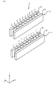
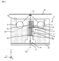
- FIG. 1 is a perspective view of a transmissive member according to Embodiment 1.
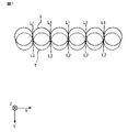
- FIG. 5 is a diagram showing the positional relationship between the lens body and the transmissive member in the optical member serving as a comparative example;
- FIG. 4 is a diagram showing the positional relationship between the optical member and the sensor array according to Embodiment 1;
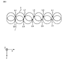
- FIG. 4 is a diagram showing the positional relationship between the lens body and the transmissive member included in the optical member according to Embodiment 1;
- FIG. 10 is a diagram showing a positional relationship between an optical member and a sensor array according to Embodiment 2;
- FIG. 10 is a diagram showing the positional relationship between the lens body and the transmissive member included in the optical member according to the second embodiment;
- FIG. 5 is a diagram showing the positional relationship between the lens body and the transmissive member in the optical member serving as a comparative example; Sectional view of the first modification of the image reading device according to the embodiment Sectional view of the second modification of the image reading device according to the embodiment Sectional view of the third modification of the image reading device according to the embodiment
- an image reading device that reads information such as images, characters, patterns, etc. on the surface of the reading object D, which is a sheet-like member including documents, banknotes, securities, etc., a substrate, a web that is a sheet-like fiber, etc.
- the image reading device 2 according to the first embodiment will be described with reference to the drawings.
- the main scanning direction is set as the X-axis
- the sub-scanning direction is set as the Y-axis
- the reading depth direction is set as the Z-axis.
- the main scanning direction and the sub-scanning direction intersect, preferably perpendicular to each other.
- the X-axis, Y-axis, and Z-axis are orthogonal to each other. The same applies to subsequent figures.
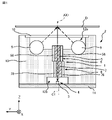
- the image reading device 2 includes a light source 9 that emits light to an object D to be read, and a light source 9 that emits the light. It comprises a transmission plate 10 for transmission, and an optical member 1 having a plurality of lens bodies for converging the light reflected by the object D to be read.
- the image reader 2 further includes a sensor array 4 having a plurality of sensor elements 3 that receive light converged by the optical member 1, and a sensor substrate 11 on which the sensor array 4 is mounted.
- the image reader 2 further includes a housing 12 to which the transmission plate 10 and the sensor substrate 11 are attached and which accommodates the light source 9, the optical member 1, and the sensor array 4 inside.
- the light source 9 is a linear light source that irradiates linear light as indicated by the dashed arrow in FIG. Formed with a light source.
- a sidelight light source is a light source having a light guide extending in the X-axis direction and a light source element arranged at the end of the light guide in the X-axis direction.
- the light emitted from the light source 9 and used for reading the information on the reading object D is, for example, visible light.
- the transmission plate 10 is attached to the housing 12 so as to block the opening 12a of the housing 12 facing the object D to be read.
- the transmission plate 10 transmits light emitted by the light source 9 .
- a member such as transparent glass or transparent resin, which has a high transmittance so that the light can be received by the sensor element 3 .
- the transmission plate 10 has a flat plate-like shape extending in the main scanning direction and the sub-scanning direction and having both flat surfaces.
- the surface of the transmission plate 10 opposite to the surface that closes the opening 12a of the housing 12 forms a reading surface of the object D to be read.
- the reading surface regulates the reading position of the object D to be read.
- the housing 12 has a box-like shape with an opening 12a facing the reading object D and an opening 12b facing the opposite side of the opening 12a.
- the housing 12 is made of a member that blocks light from the outside, for example, a metal including aluminum, iron, or the like, a resin, or the like.
- the light source 9, the optical member 1, and the sensor array 4 housed in the housing 12 are directly or indirectly attached to and held by the housing 12.
- the housing 12 prevents light from entering the light receiving section, specifically the sensor element 3 , from the outside of the image reading device 2 . Further, the housing 12 prevents foreign matter such as dust and moisture from entering the inside of the image reading device 2 .
- the sensor substrate 11 is a substrate made of resin such as glass epoxy.
- the sensor substrate 11 is provided with a plurality of sensor elements 3 and other components (not shown) such as a drive circuit and a signal processing circuit.
- the sensor substrate 11 is attached to the housing 12 in a state in which the opening 12b is closed in such a manner that the sensor element 3 is positioned in the opening 12b at the bottom of the housing 12 in the vertical direction.
- a plurality of sensor elements 3 are arranged in the main scanning direction and fixed to the sensor substrate 11 by a fixing member such as an adhesive.
- Each sensor element 3 is provided for each lens body 5 and receives light converged by the corresponding lens body 5 .
- Each sensor element 3 is preferably provided at a position through which the optical axis AX1 of the corresponding lens body 5 passes.
- each sensor element 3 is formed by a sensor IC (Integrated Circuit).
- the sensor element 3 receives light converged by the corresponding lens body 5, photoelectrically converts the light into an electric signal, and outputs the electric signal.
- the electrical signal output by the sensor element 3 is converted into image information by a signal processing circuit.
- An optical axis AX1 of the lens body 5 is parallel to the Z axis.
- the XY plane is perpendicular to the optical axis AX1 of the lens body 5. FIG. The XY plane is also called a plane perpendicular to the optical axis.
- the optical member 1 includes a lens array 6 having a plurality of lens bodies 5 arranged in a line in the main scanning direction, and a plurality of lenses for allowing light incident from one end surface to exit from the other end surface.
- a transmissive member array 8 having transmissive members 7 of .
- the lens array 6 has a plurality of lens bodies 5 and two side plates 56 sandwiching the plurality of lens bodies 5 .
- the plurality of lens bodies 5 are arranged in the main scanning direction while being in contact with each other.
- Each lens body 5 converges the light from the object D to be read.
- the extending direction of the optical axis AX1 of the lens body 5 is orthogonal to each of the main scanning direction and the sub-scanning direction. In other words, the optical axis AX1 of the lens body 5 extends parallel to the Z axis.
- the lens body 5 converges the light emitted from the light source 9 and reflected by the object D to be read.
- the lens body 5 preferably has a cylindrical shape, has a different refractive index in the radial direction, and is preferably formed of a rod lens that is a graded refractive index lens that forms an erect equal-magnification image.
- the two side plates 56 face each other across the plurality of lens bodies 5 in the Y-axis direction.
- the side plate 56 is formed of a plate-shaped member having a light-shielding property, for example, a metal containing aluminum, iron, or the like, a resin, or the like.
- the space between the two side plates 56 is preferably filled with a light-shielding adhesive. This suppresses the relative positional deviation between each lens body 5 and each side plate 56 .
- the transmission member array 8 prevents the images formed by the lens bodies 5 adjacent to each other from overlapping, in other words, separates the optical paths of the light converged by the lens bodies 5 adjacent to each other.
- the transmission member array 8 has a plurality of transmission members 7 and two side plates 78 sandwiching the plurality of transmission members 7 .
- the plurality of transmissive members 7 are arranged in the main scanning direction while being in contact with each other.
- Each transparent member 7 is provided for each lens body 5 , and is provided at a position closer to the reading object D than the corresponding lens body 5 or at a position farther from the reading target D than the corresponding lens body 5 .
- the transmissive member 7 is located farther from the object D to be read than the lens body 5 , in other words, located between the lens body 5 and the sensor element 3 .
- Each transmissive member 7 is provided in contact with the end portion of the lens body 5 in the direction of the optical axis AX1, specifically, the end portion on the Z-axis negative direction side.
- the transmissive members 7 are arranged in a row in the main scanning direction, shifted at least in the sub-scanning direction, in other words, at least in the Y-axis direction, from the corresponding lens body 5 .
- the plurality of transmissive members 7 are arranged in a row in the X-axis direction while being displaced from the plurality of lens bodies 5 in the Y-axis direction.
- the optical axis AX1 of each lens body 5 and the central axis C1 of the transmissive member 7 corresponding to the lens body 5 are shifted at least in the sub-scanning direction.
- the transmissive member 7 is formed of a member having a uniform refractive index regardless of the position, and has a columnar shape extending along the optical axis AX1 of the lens body 5.
- a member with a uniform refractive index means that the refractive index at any position of the member is within a defined range that allows manufacturing errors.
- the transmissive member 7 is a columnar member made of glass or resin having uniform refractive index and transmittance regardless of position.
- the transmission member 7 is preferably formed of a member with sufficiently small strain, for example, a member with no strain. In Embodiment 1, the transmissive member 7 has a cylindrical shape with the same diameter as the lens body 5 .
- the transmission member 7 transmits light emitted from the light source 9 .
- the transmissive member 7 allows light to enter from one end face and emit light from the other end face.
- the transmissive member 7 transmits light incident on the end face facing the lens body 5 from the lens body 5, that is, the end face facing the positive Z-axis direction, to the end face facing the sensor element 3, that is, the negative Z-axis direction. emitted from the end face facing the
- the two side plates 78 face each other across the plurality of transmissive members 7 in the Y-axis direction.
- the side plate 78 is made of a plate-like light-shielding member, such as a metal containing aluminum, iron, or the like, a resin, or the like.
- the space between the two side plates 78 is preferably filled with a light-shielding adhesive. This prevents the transmission members 7 and the side plates 78 from being displaced relative to each other.
- the side surface of the transmissive member 7, in other words, the outer peripheral surface of the transmissive member 7 around the Z axis is treated to suppress diffuse reflection of light incident on the side surface from the outside and to suppress specular reflection of light incident on the side surface from the outside.
- the transmissive member 7 includes a cylindrical member 71 and a reflection suppressing member 72 formed of a cylindrical member whose inner peripheral surface contacts the outer peripheral surface of the cylindrical member 71 . have.
- the transmissive member 7 is formed by applying a reflection suppressing member 72 made of black resin to the outer peripheral surface of the cylindrical member 71 .
- the reflection suppressing member 72 is made of black resin and suppresses reflection of light from the side surface of the transmissive member 7 . Furthermore, the anti-reflection member 72 absorbs light from the inside of the transmissive member 7 to the outside through the side surface. A light shielding adhesive filled between the two side plates 78 may be used as the reflection suppressing member 72 .
- FIG. 5 shows a comparative example in which the lens body and the transparent member are not displaced in the sub-scanning direction.
- the configuration of the image reading device 90 shown in FIG. 5 is the same as that of the image reading device 2, but is different from the image reading device 2 in that the plurality of lens bodies 91 and the plurality of transmissive members 92 are not displaced in the Y-axis direction. different.
- FIG. 5 is a view of the lens array provided in the image reading device 90 as viewed in the positive direction of the Z axis.
- the outer shape of the lens body 91 is indicated by a solid line
- the outer shape of the transmissive member 92 is indicated by a dotted line.
- the plurality of lens bodies 91 are arranged in the main scanning direction while being in contact with each other.
- the plurality of transmissive members 92 are arranged in the main scanning direction while being in contact with each other.
- the diameter of the transmissive member 92 becomes smaller than the diameter of the lens body 91 due to an error in manufacturing the transmissive member 92, the central axis of each transmissive member 92 and the optical axis of each lens body 91 are shifted.
- the end surface of the transparent member 92 at the left end in FIG. 5 faces and contacts the end surfaces of the two lens bodies 91 located at the left end. Therefore, the light emitted from two lens bodies 91 adjacent to each other enters one transmission member 92, and the images formed by the two lens bodies 91 adjacent to each other are superimposed.
- a structure for suppressing the end surface of one transmissive member 92 from facing the end surfaces of a plurality of lens bodies 91 as shown in FIG. 5 will be described below.
- the diameter of the transmission member 7 may be smaller than the diameter of the lens body 5 due to manufacturing errors of the transmission member 7 . be.
- the optical axis AX1 of each lens body 5 and the central axis C1 of the transmissive member 7 corresponding to the lens body 5 are shifted in the sub-scanning direction.
- the contact point L1 of the two lens bodies 5 in contact with each other and the contact point L2 of the two transparent members 7 in contact with each other corresponding to the two lens bodies 5 in contact with each other. is deviated at least in the sub-scanning direction.
- the contact point L2 of the member 7 is displaced in the Y-axis direction.
- the point of contact L1 of the two lens bodies 5 located at the left end and in contact with each other and the point of contact L2 of the two transmissive members 7 located at the left end and in contact with each other are located in the Y-axis direction. and Z-axis directions.
- the optical axis AX1 of each lens body 5 and the central axis C1 of the transmissive member 7 corresponding to the lens body 5 are deviated at least in the sub-scanning direction.
- the end surface of the transmissive member 7 does not face the end surfaces of the plurality of lens bodies 5 , but only faces the corresponding one end surface of the lens body 5 .
- the reflection suppressing member 72 is provided on the side surface of the transmissive member 7 as described above, the light reaching the side surface of the adjacent transmissive member 7 is absorbed.
- the central axis C1 of the transmissive member 7 and the optical axis AX1 of the lens body 5 are deviated at least in the sub-scanning direction, and the antireflection member 72 is provided on the side surface of the transmissive member 7.
- the optical paths of the converged light are separated. As a result, overlapping of images formed by two lens bodies 5 adjacent to each other is suppressed.
- part of the light that has entered one end surface of the transmission member 7 from the lens body 5 travels straight through the transmission member 7 and reaches the sensor element 3 .
- Another part of the light that has entered one end surface of the transmissive member 7 from the lens body 5 reaches the side surface of the transmissive member 7 . If the incident angle when reaching the side surface of the transmissive member 7 is greater than or equal to the critical angle, the light is totally reflected, travels straight through the transmissive member 7 , and reaches the sensor element 3 .
- the incident angle on the side surface of the transmissive member 7 is small, so that the light does not undergo total reflection. , is refracted, enters the reflection suppression member 72 provided on the side surface of the transmission member 7, and is absorbed.
- the light incident from one end surface of the transmissive member 7 reaches the side surface of the transmissive member 7. Therefore, direct emission from the other end surface is suppressed.
- the light incident on one end face of the transmissive member 7 at a large tilt angle with respect to the central axis C1 does not reach the other end face of the transmissive member 7 and is not emitted from the other end face of the transmissive member 7 .
- the light emitted from the transmissive member 7 is light whose incident angle on the side surface of the transmissive member 7 is equal to or greater than the critical angle.
- the amount of light received by the sensor element 3 when the central axis C1 of the transparent member 7 and the optical axis AX1 of the lens body 5 are deviated is such that the central axis C1 of the transparent member 7 and the optical axis AX1 of the lens body 5 are aligned. is smaller than the amount of light received by the sensor element 3 at that time.
- the deviation between the central axis C1 of the transmissive member 7 and the optical axis AX1 of the lens body 5 must be adjusted so that the amount of light received by the sensor element 3 can read the information on the object D to be read. It is preferable that the amount of light is within a range that provides the required amount of light.
- the central axis C1 of at least one of the transmissive members 7 coincide with the optical axis AX1 of the corresponding lens body 5 .
- the optical member 1 included in the image reading device 2 according to Embodiment 1 includes a plurality of lens bodies 5 and a plurality of transmissive members 7 respectively corresponding to the lens bodies 5 . Since the optical axis AX1 of the lens body 5 and the central axis C1 of the transmissive member 7 corresponding to the lens body 5 are deviated at least in the sub-scanning direction, the end surfaces of the respective lens bodies 5 are aligned with one corresponding transmissive member. It faces only the end face of 7.
- the cross-sectional shape of the lens body 5 on a plane perpendicular to the optical axis has a length in the main scanning direction at a position shifted in the sub-scanning direction from a position passing through the optical axis, rather than a length in the main scanning direction at a position passing through the optical axis. is a short shape.
- the cross-sectional shape of the transmissive member 7 on the plane perpendicular to the optical axis has a length in the main scanning direction at a position shifted in the sub-scanning direction from a position passing through the central axis than a length in the main scanning direction at a position passing through the central axis. is a short shape.
- the transmissive member 7 Since the transmissive member 7 is displaced at least in the sub-scanning direction with respect to the corresponding lens body 5, the end surface of the lens body 5 does not face the end surfaces of two or more transmissive members 7, and the end surface of the lens body 5 is It faces only the end face of one corresponding transmissive member 7 .
- the transmissive member 7 has a reflection suppressing member 72 formed on the side surface. Therefore, even if an error occurs in the arrangement position of at least one of the lens body 5 and the transmission member 7, the end faces of the transmission members 7 do not face the end faces of the plurality of lens bodies 5, and the lens bodies are adjacent to each other. The optical paths of the light emitted from 5 are separated. As a result, the optical member 1 and the image reading device 2 are obtained in which overlapping of images formed by the lens body 5 is suppressed.
- Embodiment 2 The arrangement method of the lens body 5 and the transmissive member 7 is not limited to the above example.
- FIG. 8 and FIG. 9 which is a view of the lens array 6 viewed in the positive direction of the Z-axis
- the plurality of lens bodies 5 included in the optical member 1 included in the image reading device 2 according to the second embodiment are separated from each other.
- a plurality of transmissive members 7 are arranged with a space therebetween.
- the lens bodies 5 are arranged at regular intervals, and the transmissive members 7 are arranged at irregular intervals. Therefore, in FIG. 8, the central axis C1 of the leftmost transmissive member 7 coincides with the optical axis AX1 of the corresponding lens body 5, but the central axis C1 of the other transmissive members 7 coincides with the optical axis AX1 of the corresponding lens body 5. is deviated from
- the optical axis AX1 of each lens body 5 and the central axis C1 of the transmissive member 7 corresponding to the lens body 5 are aligned at least in the sub-scanning direction. misaligned in direction.
- FIG. 10 shows a comparative example in which the lens body and transparent member are not displaced in the sub-scanning direction.
- the configuration of an image reading device 90 shown in FIG. 10 is the same as that of the image reading device 2 according to Embodiment 2, except that the plurality of lens bodies 93 and the plurality of transparent members 94 are not displaced in the Y-axis direction. It differs from the image reading device 2 .
- FIG. 10 is a view of the lens array included in the image reading device 90 as seen in the positive direction of the Z axis.
- the outer shape of the lens body 93 is indicated by solid lines
- the outer shape of the transmissive member 94 is indicated by dotted lines.
- the plurality of lens bodies 93 are arranged in the main scanning direction at intervals.
- the plurality of transmissive members 94 are arranged in the main scanning direction at intervals.
- the diameter of the lens body 93 and the diameter of the transmissive member 94 are the same, and each has a cylindrical shape.
- each transmissive member 94 and the optical axis of each lens body 93 may deviate.
- the end surfaces of the transmissive members 94 at both ends face the corresponding end surfaces of the lens body 93, but in FIG. , abut on the end face of the corresponding lens body 93 and the end face of another lens body 93 adjacent to the lens body 93 . Therefore, the light emitted from two lens bodies 93 adjacent to each other enters one transmission member 94, and the images formed by the two lens bodies 93 adjacent to each other are superimposed.
- a structure for suppressing the end surface of one transmission member 94 from facing the end surfaces of a plurality of lens bodies 93 as shown in FIG. 10 will be described below.
- an error may occur in the arrangement position of at least one of the lens body 5 and the transmissive member 7.
- two lens bodies 5 adjacent to each other on the XY plane that is a plane perpendicular to the optical axis AX1 of the lens body 5, that is, the plane perpendicular to the optical axis.
- the optical axis AX1 of each lens body 5 and the central axis C1 of the transmissive member 7 corresponding to the lens body 5 are deviated at least in the sub-scanning direction.
- the end face of the transmissive member 7 does not face the end faces of the plurality of lens bodies 5 , but faces the corresponding end face of one lens body 5 .
- the optical member 1 included in the image reading apparatus 2 according to the second embodiment includes a plurality of lens bodies 5 arranged at intervals and corresponding to the lens bodies 5 arranged at intervals.
- the optical axis AX1 of the lens body 5 and the central axis C1 of the transmission member 7 corresponding to the lens body 5 are shifted at least in the sub-scanning direction.
- the transmissive member 7 has a reflection suppressing member 72 formed on the side surface. Therefore, even if an error occurs in the arrangement position of at least one of the lens body 5 and the transmission member 7, the end faces of the transmission members 7 do not face the end faces of the plurality of lens bodies 5, and the lens bodies are adjacent to each other.
- the optical paths of the light emitted from 5 are separated. As a result, the optical member 1 and the image reading device 2 are obtained in which overlapping of images formed by the lens body 5 is suppressed.
- the present disclosure is not limited to the examples of the embodiments described above.
- the arrangement of the constituent elements of the optical member 1 is not limited to the above example.
- the lens array 6 and the transparent member array 8 may be spaced apart in the Z-axis direction and held by the housing 12 .
- the transparent member array 8 may be provided at a position closer to the object D to be read than the lens array 6 is.
- the optical member 1 includes a transmission member array 8 having a plurality of transmission members 7 for emitting light incident on one end face from the object D to be read from the other end face; and a lens array 6 having a plurality of lens bodies 5 for converging the light emitted from the other end surface of 7 and forming an image on each sensor element 3 .
- the other end surface of the transmission member 7 of the transmission member array 8 and the end surface of the lens body 5 of the lens array 6 are in contact with each other, but the transmission member 7 and the lens body 5 are shown in FIG. , may be spaced apart from each other.
- the arrangement position of the sensor element 3 is not limited to the above example.
- the arrangement interval of the sensor elements 3 in the X-axis direction may be the same as or different from the arrangement interval of the lens bodies 5 in the X-axis direction.
- the method of arranging the lens body 5 and the transparent member 7 is not limited to the above example.
- the lens bodies 5 may be arranged at uneven intervals and the transmissive members 7 may be arranged at regular intervals.
- the transmissive member 7 may have a cylindrical shape with a larger diameter than the lens body 5 .
- the plurality of transmissive members 7 may be arranged side by side in contact with each other, and the plurality of lens bodies 5 may be provided at intervals.
- the lens body 5 and the transmissive member 7 may not have a cylindrical shape.
- at least one of the lens body 5 and the transmissive member 7 has a cross-sectional shape on the XY plane, that is, a plane perpendicular to the optical axis, such as an ellipse, a polygon, or a shape having a combination of curved lines and straight lines. It may be formed in the body.
- the cross-sectional shape of the lens body 5 on the plane perpendicular to the optical axis is longer than the length in the main scanning direction at the position passing through the optical axis. Any shape with a short length in the direction may be used.
- the cross-sectional shape of the transmissive member 7 on the plane perpendicular to the optical axis is longer in the main scanning direction at a position that passes through the central axis than in the main scanning direction at a position that passes through the central axis. is short.
- the cross-sectional shape of the lens body 5 and the transmissive member 7 may be a shape in which the length in the main scanning direction decreases toward the end in the sub scanning direction.
- the cross-sectional shapes of the lens body 5 and the transmissive member 7 may have portions with the same length in the main scanning direction even if the positions in the sub-scanning direction are different.
- the material of the transmissive member 7 is not limited to the above examples.
- the transmissive member 7 may be formed of any member that transmits light emitted from the light source 9 and used for reading the object D to be read.
- the transmissive member 7 may be made of germanium, acrylic resin, glass, or the like.
- the material of the reflection suppressing member 72 is not limited to the above examples.
- the reflection suppressing member 72 may be formed of any member that suppresses reflection of light emitted from the light source 9 and used to read the object D to be read.
- the object D to be read moves relative to the fixed image reading device 2, but the image reading device 2 moves relative to the fixed object D to read.
- the information on the object D to be read may be read.
- Conveyance of the reading object D in the sub-scanning direction, that is, the conveyance direction may be realized by conveying the reading object D itself, or may be realized by moving the image reading device 2 .
- the position of the light source 9 is not limited to the above example.
- the image reading device 2 may include the light source 9 located on the Z-axis positive direction side of the transparent plate 10 .
- the object to be read D may be conveyed between the light source 9 and the transparent plate 10 .
- the light source 9 may be provided outside the image reading device 2 . Specifically, in both the case where the optical member 1 converges the reflected light reflected by the reading object D and the case where the optical member 1 converges the transmitted light transmitted through the reading object D, the light source 9 is It may be provided outside the housing 12 .
- the transmission plate 10 transmits the light emitted by the light source 9, and the transmitted light is not limited to visible light.
- the transmission plate 10 may be formed of a member that transmits infrared rays, ultraviolet rays, or the like, for example. Even if it is made of a member that does not transmit visible light, it can be used as the transmission plate 10 as long as it transmits the light emitted by the light source 9 .
- the transmissive plate 10 does not have to be attached to the image reading device 2, specifically the housing 12, if it is not necessary to form a transport surface for the object D to be read.
- the configuration of the light source 9 is not limited to the above example, and as an example, includes a plurality of LEDs (Light Emitting Diodes) and an LED substrate extending in the main scanning direction and formed with each LED. good too. In this case, the plurality of LEDs should be arranged in an array along the main scanning direction. Although two light sources 9 are arranged with the optical member 1 therebetween in FIG. 1, one light source 9 may be arranged.
- LEDs Light Emitting Diodes
- the position where the sensor substrate 11 is provided is not limited to the example described above, and may be any position as long as the sensor array 4 provided on the sensor substrate 11 can receive light converged by the lens array 6 .
- the lens body 5 may be any lens body for an erect equal-magnification optical system.
- a microlens may be used as the lens body 5 .
- the structure of the transmissive member 7 is not limited to the above example, and may be arbitrary as long as the light incident from one end surface can be emitted from the other end surface.
- the transmissive member 7 may have a columnar shape in which a through-hole is formed penetrating in the extending direction of the central axis C1. In other words, the transmissive member 7 may have a cylindrical shape.
- D read object 1 optical member, 2, 90 image reader, 3 sensor element, 4 sensor array, 5, 91, 93 lens body, 6 lens array, 56 side plate, 7, 92, 94 transparent member, 71 cylindrical member , 72 reflection suppression member, 8 transmission member array, 78 side plate, 9 light source, 10 transmission plate, 11 sensor substrate, 12 housing, 12a, 12b opening, AX1 optical axis, C1 central axis, L1, L2 contacts, L3, L4 Midpoint.
Landscapes
- Engineering & Computer Science (AREA)
- Multimedia (AREA)
- Signal Processing (AREA)
- Physics & Mathematics (AREA)
- General Physics & Mathematics (AREA)
- Optics & Photonics (AREA)
- Facsimile Heads (AREA)
- Facsimile Scanning Arrangements (AREA)
- Optical Elements Other Than Lenses (AREA)
Priority Applications (4)
| Application Number | Priority Date | Filing Date | Title |
|---|---|---|---|
| US18/566,123 US12289431B2 (en) | 2021-06-09 | 2022-06-08 | Optical member and image reading device |
| CN202280039668.XA CN117413510A (zh) | 2021-06-09 | 2022-06-08 | 光学部件以及图像读取装置 |
| DE112022002969.2T DE112022002969T5 (de) | 2021-06-09 | 2022-06-08 | Optisches Element und Bildlesevorrichtung |
| JP2022572306A JP7430823B2 (ja) | 2021-06-09 | 2022-06-08 | 光学部材および画像読取装置 |
Applications Claiming Priority (2)
| Application Number | Priority Date | Filing Date | Title |
|---|---|---|---|
| JP2021-096276 | 2021-06-09 | ||
| JP2021096276 | 2021-06-09 |
Publications (1)
| Publication Number | Publication Date |
|---|---|
| WO2022260108A1 true WO2022260108A1 (ja) | 2022-12-15 |
Family
ID=84426129
Family Applications (1)
| Application Number | Title | Priority Date | Filing Date |
|---|---|---|---|
| PCT/JP2022/023196 Ceased WO2022260108A1 (ja) | 2021-06-09 | 2022-06-08 | 光学部材および画像読取装置 |
Country Status (5)
| Country | Link |
|---|---|
| US (1) | US12289431B2 (https=) |
| JP (1) | JP7430823B2 (https=) |
| CN (1) | CN117413510A (https=) |
| DE (1) | DE112022002969T5 (https=) |
| WO (1) | WO2022260108A1 (https=) |
Cited By (1)
| Publication number | Priority date | Publication date | Assignee | Title |
|---|---|---|---|---|
| WO2024009538A1 (ja) * | 2022-07-04 | 2024-01-11 | 日本板硝子株式会社 | 光学装置、イメージセンサ、および光学装置の製造方法 |
Families Citing this family (1)
| Publication number | Priority date | Publication date | Assignee | Title |
|---|---|---|---|---|
| WO2022163157A1 (ja) * | 2021-01-29 | 2022-08-04 | 三菱電機株式会社 | 画像読取装置 |
Citations (3)
| Publication number | Priority date | Publication date | Assignee | Title |
|---|---|---|---|---|
| JPH01124802A (ja) * | 1987-11-10 | 1989-05-17 | Matsushita Electric Ind Co Ltd | 情報読取用レンズアレイの製造方法 |
| JPH06342131A (ja) * | 1992-11-04 | 1994-12-13 | Canon Inc | レンズアレイ及びそれを用いた密着型イメージセンサー |
| WO2020196168A1 (ja) * | 2019-03-25 | 2020-10-01 | 三菱電機株式会社 | 画像読取装置 |
Family Cites Families (12)
| Publication number | Priority date | Publication date | Assignee | Title |
|---|---|---|---|---|
| US8614413B2 (en) * | 2007-01-31 | 2013-12-24 | Ricoh Company, Ltd. | Image reading apparatus to illuminate light on an original document with an optical member having four planes positioned such that the light incident side is smaller in size than the light exit side |
| US8358457B2 (en) * | 2009-08-10 | 2013-01-22 | Honeybee Robotics, Ltd. | Miniature rotating transmissive optical drum scanner |
| CN102667565B (zh) * | 2009-12-22 | 2015-05-13 | 恩普乐股份有限公司 | 透镜阵列以及具备该透镜阵列的光学模块 |
| CN108702427B (zh) * | 2016-03-01 | 2019-12-10 | 三菱电机株式会社 | 图像读取装置 |
| JP6734169B2 (ja) * | 2016-09-28 | 2020-08-05 | 株式会社沖データ | レンズユニット、露光装置、ledヘッド、及び画像形成装置 |
| JP7005218B2 (ja) * | 2017-08-09 | 2022-01-21 | 株式会社東芝 | レンズミラーアレイおよび画像形成装置 |
| DE112019005398B4 (de) * | 2018-10-31 | 2024-03-21 | Mitsubishi Electric Corporation | Linsenkörper-bondierstruktur, bildlesevorrichtung und verfahren für bondierlinsenkörper |
| JP7293791B2 (ja) * | 2019-03-26 | 2023-06-20 | 富士フイルムビジネスイノベーション株式会社 | 光学装置、画像読取装置、および画像形成装置 |
| JP7211316B2 (ja) * | 2019-09-26 | 2023-01-24 | 三菱電機株式会社 | 画像読取装置及びその製造方法 |
| JP2021096276A (ja) | 2019-12-13 | 2021-06-24 | キヤノン株式会社 | ベルト搬送装置、画像形成装置、記録材冷却装置 |
| JP7479920B2 (ja) * | 2020-05-11 | 2024-05-09 | シャープ株式会社 | 光学部材、光走査装置及び画像形成装置 |
| US11683433B1 (en) * | 2022-08-31 | 2023-06-20 | Toshiba Tec Kabushiki Kaisha | Image reading apparatus |
-
2022
- 2022-06-08 JP JP2022572306A patent/JP7430823B2/ja active Active
- 2022-06-08 US US18/566,123 patent/US12289431B2/en active Active
- 2022-06-08 WO PCT/JP2022/023196 patent/WO2022260108A1/ja not_active Ceased
- 2022-06-08 DE DE112022002969.2T patent/DE112022002969T5/de active Pending
- 2022-06-08 CN CN202280039668.XA patent/CN117413510A/zh active Pending
Patent Citations (3)
| Publication number | Priority date | Publication date | Assignee | Title |
|---|---|---|---|---|
| JPH01124802A (ja) * | 1987-11-10 | 1989-05-17 | Matsushita Electric Ind Co Ltd | 情報読取用レンズアレイの製造方法 |
| JPH06342131A (ja) * | 1992-11-04 | 1994-12-13 | Canon Inc | レンズアレイ及びそれを用いた密着型イメージセンサー |
| WO2020196168A1 (ja) * | 2019-03-25 | 2020-10-01 | 三菱電機株式会社 | 画像読取装置 |
Cited By (1)
| Publication number | Priority date | Publication date | Assignee | Title |
|---|---|---|---|---|
| WO2024009538A1 (ja) * | 2022-07-04 | 2024-01-11 | 日本板硝子株式会社 | 光学装置、イメージセンサ、および光学装置の製造方法 |
Also Published As
| Publication number | Publication date |
|---|---|
| JP7430823B2 (ja) | 2024-02-13 |
| DE112022002969T5 (de) | 2024-04-11 |
| US12289431B2 (en) | 2025-04-29 |
| JPWO2022260108A1 (https=) | 2022-12-15 |
| CN117413510A (zh) | 2024-01-16 |
| US20240251049A1 (en) | 2024-07-25 |
Similar Documents
| Publication | Publication Date | Title |
|---|---|---|
| US8014072B2 (en) | Erecting equal-magnification lens array plate, image sensor unit, and image reading device | |
| TWI609205B (zh) | Optical socket and light module with it | |
| US8638484B2 (en) | Erecting equal-magnification lens array plate, optical scanning unit, image reading device, and image writing device | |
| CN110892303B (zh) | 光插座及光模块 | |
| JP6461509B2 (ja) | 光レセプタクルおよび光モジュール | |
| JP7430823B2 (ja) | 光学部材および画像読取装置 | |
| US10382642B2 (en) | Image reading apparatus | |
| CN108780197A (zh) | 光插座、光模块及光模块的制造方法 | |
| US8817378B2 (en) | Erecting equal-magnification lens array plate, optical scanning unit, image reading device, and image writing device | |
| US20100142057A1 (en) | Erecting equal-magnification lens array plate, image sensor unit, and image reading device | |
| CN111868591A (zh) | 光插座及光模块 | |
| JP7337292B2 (ja) | 光学部材および画像読取装置 | |
| JP7283210B2 (ja) | 画像読取装置 | |
| JP6548119B2 (ja) | 光レセプタクルおよび光モジュール | |
| CN103873729A (zh) | 原稿照明装置、紧密附着型图像传感器模块及图像读取装置 | |
| WO2022064777A1 (ja) | 画像読取装置 | |
| US7532402B2 (en) | Imaging device for imaging a long object | |
| US10234643B2 (en) | Optical connector | |
| US12519896B2 (en) | Image reading device comprising a lens array including first lens bodies and second lens bodies, a light receiver and light blocking plates that are between the light receiver and second lens bodies, the thickness of the light blocking plates equal to or greater than the second lens bodies thickness | |
| JP7387801B2 (ja) | 光モジュール及び反射型エンコーダ | |
| CN114391246B (zh) | 图像读取装置 | |
| CN115144979A (zh) | 光插座及光模块 | |
| JP6649090B2 (ja) | 光レセプタクルおよび光モジュール | |
| JP4417368B2 (ja) | イメージセンサ | |
| JP6594562B2 (ja) | 画像読取装置 |
Legal Events
| Date | Code | Title | Description |
|---|---|---|---|
| ENP | Entry into the national phase |
Ref document number: 2022572306 Country of ref document: JP Kind code of ref document: A |
|
| 121 | Ep: the epo has been informed by wipo that ep was designated in this application |
Ref document number: 22820287 Country of ref document: EP Kind code of ref document: A1 |
|
| WWE | Wipo information: entry into national phase |
Ref document number: 202280039668.X Country of ref document: CN Ref document number: 18566123 Country of ref document: US |
|
| WWE | Wipo information: entry into national phase |
Ref document number: 112022002969 Country of ref document: DE |
|
| 122 | Ep: pct application non-entry in european phase |
Ref document number: 22820287 Country of ref document: EP Kind code of ref document: A1 |
|
| WWG | Wipo information: grant in national office |
Ref document number: 18566123 Country of ref document: US |