WO2022255138A1 - イネーブルスイッチ装置及びこれを備えた負荷駆動制御装置 - Google Patents
イネーブルスイッチ装置及びこれを備えた負荷駆動制御装置 Download PDFInfo
- Publication number
- WO2022255138A1 WO2022255138A1 PCT/JP2022/021056 JP2022021056W WO2022255138A1 WO 2022255138 A1 WO2022255138 A1 WO 2022255138A1 JP 2022021056 W JP2022021056 W JP 2022021056W WO 2022255138 A1 WO2022255138 A1 WO 2022255138A1
- Authority
- WO
- WIPO (PCT)
- Prior art keywords
- state
- switch
- switch device
- enable switch
- enable
- Prior art date
- Legal status (The legal status is an assumption and is not a legal conclusion. Google has not performed a legal analysis and makes no representation as to the accuracy of the status listed.)
- Ceased
Links
Images


Classifications
-
- B—PERFORMING OPERATIONS; TRANSPORTING
- B25—HAND TOOLS; PORTABLE POWER-DRIVEN TOOLS; MANIPULATORS
- B25J—MANIPULATORS; CHAMBERS PROVIDED WITH MANIPULATION DEVICES
- B25J13/00—Controls for manipulators
- B25J13/06—Control stands, e.g. consoles, switchboards
-
- B—PERFORMING OPERATIONS; TRANSPORTING
- B25—HAND TOOLS; PORTABLE POWER-DRIVEN TOOLS; MANIPULATORS
- B25J—MANIPULATORS; CHAMBERS PROVIDED WITH MANIPULATION DEVICES
- B25J19/00—Accessories fitted to manipulators, e.g. for monitoring, for viewing; Safety devices combined with or specially adapted for use in connection with manipulators
- B25J19/06—Safety devices
-
- B—PERFORMING OPERATIONS; TRANSPORTING
- B25—HAND TOOLS; PORTABLE POWER-DRIVEN TOOLS; MANIPULATORS
- B25J—MANIPULATORS; CHAMBERS PROVIDED WITH MANIPULATION DEVICES
- B25J9/00—Program-controlled manipulators
- B25J9/16—Program controls
- B25J9/1674—Program controls characterised by safety, monitoring, diagnostic
-
- G—PHYSICS
- G05—CONTROLLING; REGULATING
- G05B—CONTROL OR REGULATING SYSTEMS IN GENERAL; FUNCTIONAL ELEMENTS OF SUCH SYSTEMS; MONITORING OR TESTING ARRANGEMENTS FOR SUCH SYSTEMS OR ELEMENTS
- G05B2219/00—Program-control systems
- G05B2219/30—Nc systems
- G05B2219/39—Robotics, robotics to robotics hand
- G05B2219/39443—Portable, adapted to handpalm, with joystick, function keys, display
Definitions
- the present disclosure relates to an enable switch device and a load drive control device including the same.
- teaching tasks such as robot controller initial settings and robot operation are often performed using a teaching pendant attached to the robot controller.
- the worker needs to approach the robot while operating the teaching pendant. For this reason, serious accidents may occur due to failures of various devices including robots or operator errors.
- the teaching pendant is usually equipped with a 3-position switch.
- a 3-position switch By using a 3-position switch, the robot can be brought to an emergency stop by an action such as releasing the operation switch or firmly gripping the operation switch, ensuring the safety of the operator.
- Patent Document 1 discloses an enabling device that includes two 3-position switches and two monitor circuits that monitor the states of the 3-position switches. Two monitoring devices are connected to each of the two three-position switches. With such a configuration, safe operation can be ensured even if one of the two monitor circuits is short-circuited.
- the conventional enable switch device disclosed in Patent Document 1 outputs the state of the 3-position switch via a plurality of electromagnetic switching relays.
- the electromagnetic switching relay has a short life and requires frequent replacement. For this reason, there is a problem that the replacement cost of parts in the enable switch device increases.
- the present disclosure has been made in view of this point, and provides an enable switch device capable of determining an operation state with a simple configuration and capable of detecting a failure of an internal three-position switch, and a load drive control device having the same. That's what it is.
- the enable switch device has a first position that is in an OFF state when not operated, a second position that is in an ON state during intermediate operation, and a third position that is in an OFF state when fully operated. , comprising at least a first switch, a second switch, and a first signal processing unit, wherein the first switch and the second switch are three-position switches;
- the first signal processing unit determines which of the first to third positions the enable switch device is in, based on the output signals of the first switch and the second switch. , the presence or absence of a failure in each of the first switch and the second switch can be detected.
- a load drive control device includes at least the enable switch device and a control device configured to communicate with the enable switch device, and when it is determined that the enable switch device is in an ON state, The control device transmits a drive permission signal to the load configured to communicate with the control device, and when it is determined that the enable switch device is in an off state, the control device sends a drive stop signal to the load. is characterized by transmitting
- the operating state can be determined with a simple configuration. Also, failure detection of the internal three-position switch becomes possible.
- the load drive control device of the present disclosure it is possible to prevent the occurrence of accidents caused by operator's operation errors, etc., and ensure the safety of the operator. In addition, it is possible to prevent the load from operating unintentionally.
- FIG. 1 is a schematic configuration diagram of a robot system according to Embodiment 1.
- FIG. FIG. 2 is a schematic configuration diagram of the load drive control device.
- FIG. 3 is a schematic diagram showing the transition of the operation state of the enable switch device.
- FIG. 4 is a diagram showing the determination result of the first state determination unit.
- FIG. 5 is a schematic diagram showing the transition of the operation state of the enable switch device according to the second embodiment.
- FIG. 6 is a schematic configuration diagram of a load drive control device according to the third embodiment.
- FIG. 7 is a schematic diagram showing the transition of the operation state of the enable switch device.
- FIG. 8 is a diagram showing determination results of the first state determination section and the second state determination section.
- FIG. 9 is a schematic diagram showing the transition of the operation state of the enable switch device according to the fourth embodiment.
- FIG. 1 shows a schematic configuration diagram of a robot system according to this embodiment, and the robot system 1 has a robot 2 and a load drive controller 200 .
- the load drive control device 200 also has a robot controller (control device) 3 and a teaching pendant 4 .
- the robot 2 is a vertically articulated robot and has a plurality of robot arms 2a and joint shafts 2b.
- a motor M (see FIG. 2) is connected to each of the joint shafts 2b.
- the robot controller 3 is a known CPU (Central Processing Unit) or computer.
- the robot controller 3 is configured to be able to communicate with a plurality of motors M mutually. Further, the robot controller 3 controls the operations of the plurality of motors M respectively.
- the teaching pendant 4 is an input device for initializing the robot controller 3. Also, the teaching pendant 4 is a teaching device for teaching the operation of the robot 2 .
- the teaching pendant 4 has an operation switch 4a and an enable switch device 100 (see FIG. 2) connected to the operation switch 4a.
- the internal state of the enable switch device 100 changes according to the operating state of the operating switch 4a.
- the movement of the robot 2 is permitted or restricted according to this state change.
- the robot controller 3 and the teaching pendant 4 are configured to be able to exchange data with each other via the communication cable 5 .
- the robot controller 3 and the teaching pendant 4 may be configured to exchange data with each other through wireless communication.
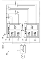
- FIG. 2 shows a schematic configuration diagram of the load drive control device
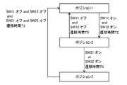
- FIG. 3 schematically shows the transition of the operation state of the enable switch device.
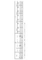
- FIG. 4 shows the determination result of the first state determination section. 2
- only the enable switch device 100 of the teaching pendant 4 is shown as a circuit diagram.
- the motors M are provided according to the number of the joint shafts 2b. Driving of each motor M is permitted or restricted according to the output signal of the enable switch device 100 .
- the enable switch device 100 has a first switch SW1, a second switch SW2, and a first signal processing section .
- the enable switch device 100 also has a power supply 30 . Note that the power supply 30 may be external to the enable switch device 100 .
- the first switch SW1 and the second switch SW2 are three-position switches, each having terminals a, b, and c.
- the terminal c is a common terminal and is connected to the power supply 30 respectively. That is, the first switch SW1 is connected in parallel with the second switch SW2.
- the first switch SW1 and the second switch SW2 depending on the operation of the operation switch 4a described above, whether the terminal c and the terminal a are in a conductive state or the terminal c and the terminal b are in a conductive state. to switch.
- a terminal connected to the power supply 30 through the terminal c has a high potential (hereinafter referred to as H potential), and a terminal electrically separated from the power supply 30 has a low potential (hereinafter referred to as L potential).
- the first signal processing unit 10 is a known CPU or computer.
- the first signal processing section 10 has at least a first signal input section 11 , a first state determination section 12 and a first state output section 13 .
- the first signal input section 11 receives output signals from the first switch SW1 and the second switch SW2 and inputs them to the first state determination section 12 .
- the output signal of the first switch SW1 is represented by a combination of the potential of the terminal a and the potential of the terminal b (see FIG. 4).
- the output signal of the second switch SW2 is represented by a combination of the potential of the terminal a and the potential of the terminal b (see FIG. 4).
- the first state determination section 12 determines the operating state of the enable switch device 100 based on the signal input from the first signal input section 11 . Based on the signal input from the first signal input section 11, the first state determination section 12 detects whether or not there is a failure in each of the first switch SW1 and the second switch SW2. These will be discussed later.
- the function of the first state determination unit 12 is realized by executing predetermined software in the first signal processing unit 10.
- the first state determination section 12 is a functional block in the first signal processing section 10 .
- the first state output section 13 outputs the operation state of the enable switch device 100 based on the determination result of the first state determination section 12 .
- both the first switch SW1 and the second switch SW2 are off.
- the enabling switch device 100 is in position 1 as shown in FIG.
- the first switch SW1 is turned off when the potential of the terminal a is H potential and the potential of the terminal b is L potential.
- the first switch SW1 is turned on.
- the second switch SW2 is turned off when the potential of the terminal a is H potential and the potential of the terminal b is L potential.
- the second switch SW2 is turned on.
- the enable switch device 100 When the operating state of the enable switch device 100 is position 1, the enable switch device 100 is in the OFF state.
- the first state output section 13 outputs a signal to the robot controller 3 . Since the robot controller 3 recognizes that the enable switch device 100 is in the OFF state, it sends a drive stop signal to the motor M. As a result, the drive control of the motor M becomes impossible, and the robot 2 does not operate.
- the enable switch device 100 When the operator operates the operation switch 4a, the enable switch device 100 is configured such that the first switch SW1 first transitions to the ON state. When the first switch SW1 is on and the second switch SW2 is off, it is assumed that the enabling switch device 100 is in position 2 as shown in FIG. Also, this state is sometimes called an intermediate operation state.
- the enable switch device 100 When the operating state of the enable switch device 100 is position 2, the enable switch device 100 is in the ON state.
- the first state output section 13 outputs a signal to the robot controller 3 . Since the robot controller 3 recognizes that the enable switch device 100 is on, it sends a drive permission signal to the motor M. As a result, the drive control of the motor M becomes possible, and the robot 2 performs a predetermined operation based on the teaching contents of the teaching pendant 4 .
- both the first switch SW1 and the second switch SW2 transition to the ON state.
- the operation switch 4a is gripped strongly.
- the operating state of the enable switch device 100 is at position 3, as shown in FIG. Also, this state is sometimes called a fully operational state.
- the enable switch device 100 When the operating state of the enable switch device 100 is position 3, the enable switch device 100 is in the OFF state.
- the first state output section 13 outputs a signal to the robot controller 3 . Since the robot controller 3 recognizes that the enable switch device 100 is in the OFF state, it sends a drive stop signal to the motor M. As a result, the drive control of the motor M becomes impossible, and the robot 2 does not operate.
- the first state determination unit 12 determines that the operating state of the enable switch device 100 does not correspond to any of positions 1-3.
- both the potentials of the terminal a and the terminal b may be H potential. In this case, it is considered that a short-circuit failure has occurred between the terminals a and b.
- both the potentials of the terminal a and the terminal b may be the L potential. In this case, the contact is stuck inside the second switch SW2, and it is considered that the contact is not in contact with either the terminal a or the terminal b, that is, an open failure has occurred.
- the first state determination unit 12 determines the presence and type of failure as described above from the output signals of the first switch SW1 and the second switch SW2. It should be noted that the output signal from the first state output unit 13 is information regarding the operating state of the enable switch device 100 . Failure information of the first switch SW1 and the second switch SW2, that is, information regarding the presence or absence of failure and its type is not directly included in the output signal. However, when the first switch SW1 and the second switch SW2 are not malfunctioning, the operating state of the enable switch device 100 does not correspond to any of the positions 1-3. In such a case, the enable switch device 100 is determined to be off.
- the robot controller 3 upon receiving the output signal, the robot controller 3 sends a drive stop signal to the motor M. As a result, the drive control of the motor M becomes impossible, and the robot 2 does not operate.
- Data transmission from the first state output unit 13 to the robot controller 3 may be performed by wired communication or wireless communication.
- the determination result of the first state determination unit 12 may be stored in a storage unit (not shown).
- the storage section may be outside the first signal processing section 10 .
- the information stored in the storage section includes not only the operating state of the enable switch device 100 but also failure information of the first switch SW1 and the second switch SW2.
- the enable switch device 100 can be completely set to position 1 (first position), which is in the OFF state when not operated, and to position 2 (second position), which is in the ON state during intermediate operation. When operated, they transition to position 3 (third position), which is in the OFF state.
- the enable switch device 100 includes at least a first switch SW1, a second switch SW2, and a first signal processing section .
- Each of the first switch SW1 and the second switch SW2 is a three-position switch. Also, the first switch SW1 is connected in parallel with the second switch SW2.
- the first signal processing unit 10 is configured to determine which of the positions 1 to 3 the operating state of the enable switch device 100 is based on the respective output signals of the first switch SW1 and the second switch SW2. ing. Further, the first signal processing unit 10 is configured to detect the presence or absence of a failure in each of the first switch SW1 and the second switch SW2.
- the operating state of the enable switch device 100 can be determined with a simple configuration. As a result, it is possible to prevent the operator from falling into a dangerous state due to the operator's operation error or the like. In addition, the robot 2 can be prevented from moving unintentionally, and the robot system 1 can be safely operated.
- the robot 2 connected to the enable switch device 100 can be prevented from operating unintentionally, and the robot system 1 can be operated safely.
- the teaching pendant 4 having the enable switch device 100 can be easily replaced and repaired. As a result, downtime and operating costs of the robot system 1 can be reduced.
- the first signal processing section 10 includes at least a first signal input section 11 , a first state determination section 12 and a first state output section 13 .
- the first signal input section 11 receives the output signals of the first switch SW1 and the second switch SW2 and inputs them to the first state determination section.
- the first state determination section 12 determines which of positions 1 to 3 the enable switch device 100 is in the operating state. Also, the first state determination unit 12 detects the presence or absence of a failure in each of the first switch SW1 and the second switch SW2.
- the first state output section 13 outputs the operation state of the enable switch device 100 to the robot controller 3 based on the determination result of the first state determination section 12 .
- the first state output unit 13 may output failure information in each of the first switch SW1 and the second switch SW2 to the robot controller 3 as necessary.
- the first signal processing unit 10 By configuring the first signal processing unit 10 in this manner, it is possible to easily determine the operating state of the enable switch device 100, the presence or absence of a failure of the first switch SW1 or the second switch SW2, and the like.
- predetermined software is executed by the first signal processing unit 10 to determine the operating state of the enable switch device 100, the presence or absence of failure of the first switch SW1 and the second switch SW2, and the like. By doing so, it is possible to reduce the number of relays used compared to the conventional configuration disclosed in Patent Document 1. As a result, the replacement cycle of the enable switch device 100 and thus the teaching pendant 4 can be lengthened. Also, downtime and operating costs of the robot system 1 can be reduced.
- a load drive control device 200 includes at least an enable switch device 100 and a robot controller (control device) 3 .
- the robot controller 3 is configured to communicate with the enable switch device 100 .
- the robot controller 3 transmits a drive permission signal to the motor (load) M configured to communicate with the robot controller 3 .
- the robot controller 3 transmits a drive stop signal to the motor M.
- the robot controller 3 permits or restricts the driving of the motor M according to the state of the enable switch device 100 .
- the robot 2 can be prevented from moving unintentionally, and the robot system 1 can be safely operated.
- the robot controller 3 sends a drive stop signal to the motor M.
- the robot 2 connected to the enable switch device 100 can be prevented from operating unintentionally, and the robot system 1 can be operated safely.
- the teaching pendant 4 having the enable switch device 100 can be easily replaced and repaired, and the downtime and operating costs of the robot system 1 can be reduced.
- FIG. 5 schematically shows the transition of the operation state of the enable switch device according to this embodiment.
- the same parts as in Embodiment 1 are given the same reference numerals, and detailed explanations thereof are omitted.
- the enable switch device 100 of this embodiment differs from the enable switch device 100 of Embodiment 1 in the following points.
- the first state determination unit 12 detects the state transition and then After the transition time T1 has elapsed, it is determined that the operating state of the enable switch device 100 has transitioned.
- the first state determination unit 12 detects the state transition and after the transition time T1 has elapsed, the enable switch device 100 It is determined that the operation state of 100 has changed.
- the transition time T1 is set to 24 msec in this embodiment, it is not particularly limited to this.
- the first state determination unit 12 determines that immediately after detecting the state transition, in this case, the transition time T0 ( ⁇ T1 ), it is determined that the operation state of the enable switch device 100 has changed.
- the timing to start driving the motor M can be delayed by the transition time T1 immediately after the enable switch device 100 enters the intermediate operation state.
- the enable switch device 100 may further transition to the non-operated state.
- the robot controller 3 can quickly transmit a drive stop signal to the robot 2 by determining that the operation state of the enable switch device 100 has transitioned immediately after detecting the state transition, thereby enabling the robot 2 to operate. is stopped. This enhances worker safety.
- FIG. 6 shows a schematic configuration diagram of the load drive control device according to the present embodiment, and FIG. 7 schematically shows transition of the operation state of the enable switch device.
- FIG. 8 shows the determination results of the first state determination section and the second state determination section. It should be noted that FIG. 6 shows only the enable switch device 100 of the teaching pendant 4 as a circuit diagram, as in the first embodiment. Similarly, FIG. 6 shows only the motor M connected to one joint shaft 2b.
- the enable switch device 100 of this embodiment differs from the enable switch device 100 of Embodiment 1 in the following points.
- the enable switch device 100 includes at least first to fourth switches SW11 to SW22, a first signal processing section 10, and a second signal processing section 20.
- Each of the first to fourth switches SW11 to SW22 is a 3-position switch.
- a terminal c is a common terminal and is connected to the power supply 30, respectively. That is, the first to fourth switches SW11 to SW22 are connected in parallel with each other. Also, the operations of the first to fourth switches SW11 to SW22 are the same as the operations of the first switch SW1 and the second switch SW2 shown in the first embodiment.
- the first signal processing unit 10 is configured to determine the state of each of the first switch SW11 and the second switch SW21. That is, it is configured to determine whether the first switch SW11 and the second switch SW21 are in an ON state or an OFF state. Also, the first signal processing unit 10 is configured to detect whether or not there is a failure in the first switch SW11 and the second switch SW21.
- the first signal processing section 10 has at least a first signal input section 11, a first state determination section 12, and a first state output section 13, as in the first embodiment. Since the function of the first signal input section 11 is the same as that shown in the first embodiment, the explanation is omitted.
- the first state determination section 12 determines the respective states of the first switch SW11 and the second switch SW21 based on the signal input from the first signal input section 11 . That is, it is determined whether the first switch SW11 and the second switch SW21 are in the ON state or the OFF state. Based on the signal input from the first signal input section 11, the first state determination section 12 detects whether or not the first switch SW11 and the second switch SW21 are faulty. Here, the presence or absence and type of failure of the first switch SW11 and the second switch SW21 are detected by a method similar to that shown in the first embodiment. For example, in the first switch SW11, if the potential of the terminal a and the potential of the terminal b are both H potential, it is determined that the first switch SW11 has a short-circuit fault. In the second switch SW21, if both the potential of the terminal a and the potential of the terminal b are L potential, it is determined that the second switch SW21 has an open fault.
- the first state output unit 13 Based on the determination result of the first state determination unit 12, the first state output unit 13 outputs information about the respective states of the first switch SW11 and the second switch SW21. , and output information to the robot controller 3 as to whether they are on or off. Note that the first state output unit 13 may output failure information of each of the first switch SW11 and the second switch SW21 to the robot controller 3 .
- the function and configuration of the second signal processing section 20 are the same as those of the first signal processing section 10, respectively. However, the second signal processing section 20 handles input signals of the third switch SW12 and the fourth switch SW22.
- the second signal processing section 20 is configured to determine the state of each of the third switch SW12 and the fourth switch SW22. That is, it is configured to determine whether the third switch SW12 and the fourth switch SW22 are on or off. Further, the second signal processing section 20 is configured to detect the presence or absence of failure in each of the third switch SW12 and the fourth switch SW22.
- the second signal processing section 20 has at least a second signal input section 21 , a second state determination section 22 and a second state output section 23 .
- the second signal input section 21 receives output signals from the third switch SW12 and the fourth switch SW22 and inputs them to the second state determination section 22 .
- the second state determination section 22 determines the respective states of the third switch SW12 and the fourth switch SW22 based on the signal input from the second signal input section 21 . That is, it is determined whether the third switch SW12 and the fourth switch SW22 are in the ON state or the OFF state. Further, the second state determination section 22 detects whether or not the third switch SW12 and the fourth switch SW22 are out of order based on the signal input from the second signal input section 21 .
- the second state output unit 23 outputs information about the states of the third switch SW12 and the fourth switch SW22 based on the determination result of the second state determination unit 22, that is, the state of the third switch SW12 and the fourth switch SW22. , and output information to the robot controller 3 as to whether they are on or off.
- the second state output unit 23 may output failure information of each of the third switch SW12 and the fourth switch SW22 to the robot controller 3.
- the enable switch device 100 determines the operating state of the enable switch device 100 based on the determination result of the first signal processing section 10 and the determination result of the second signal processing section 20 .
- the first signal processing unit 10 determines only the respective states of the first switch SW11 and the second switch SW21.
- the second signal processing unit 20 determines only the respective states of the third switch SW12 and the fourth switch SW22. Therefore, based on the determination result of the first signal processing section 10 and the determination result of the second signal processing section 20, the operation state of the enable switch device 100 is finally determined.
- the operating state of the enable switch device 100 is position 2 (second position). It is determined that there is That is, the enable switch device 100 is determined to be in the ON state (intermediate operation state).
- the timing at which either the second switch SW21 or the fourth switch SW22 is turned on is the timing at which the operating state of the enable switch device 100 is determined to be the position 3 .
- the first signal processing section 10 and the second signal processing section 20 are configured to be able to communicate with each other.
- serial communication is performed between the first signal processing section 10 and the second signal processing section 20 .
- these determinations may be performed by the first signal processing unit 10, for example, the first state determination unit 12, which receives the determination result of the second state determination unit 22.
- these determinations may be performed by the second signal processing section 20, for example, the second state determination section 22, which receives the determination result of the first state determination section 12.
- either the first signal processing unit 10 or the second signal processing unit 20 or another determination unit may be provided inside the enable switch device 100 .
- the other determination section receives the determination result of the first signal processing section 10 and the determination result of the second signal processing section 20 and determines the state of the enable switch device 100 .
- the state of the enable switch device 100 may be determined by the robot controller 3 that receives the output signal of the first state output section 13 and the output signal of the second state output section 23 .
- the operating state of the enable switch device 100 can be determined with a simple configuration. As a result, it is possible to prevent the operator from falling into a dangerous state due to the operator's operation error or the like. In addition, the robot 2 can be prevented from moving unintentionally, and the robot system 1 can be safely operated.
- the presence or absence of a failure in the first to fourth switches SW1 to SW22 provided inside the enable switch device 100 and the type thereof can be easily detected.
- the robot 2 connected to the enable switch device 100 can be prevented from operating unintentionally, and the robot system 1 can be operated safely.
- the teaching pendant 4 having the enable switch device 100 can be easily replaced and repaired. As a result, downtime and operating costs of the robot system 1 can be reduced.
- the enable switch device 100 shown in the present embodiment is a so-called duplex circuit that includes two sets of combination circuits of the two switches shown in the first embodiment and the signal processing unit. Further, the enable switch device 100 shown in this embodiment is configured to correctly determine the operating state of the enable switch device 100 only when both of the two combination circuits are functioning normally.
- the first signal processing section 10 and the second signal processing section 20 are configured to be able to communicate with each other. Further, when the determination result in the first signal processing section 10 and the determination result in the second signal processing section 20 do not match, it is determined that the enable switch device 100 is in the OFF state.
- the safety of workers can be improved.
- the robot 2 can be prevented from moving unintentionally, and the robot system 1 can be safely operated.
- the robot controller 3 transmits a drive stop signal to the motor M. .
- the robot 2 connected to the enable switch device 100 can be prevented from operating unintentionally, and the robot system 1 can be operated safely. Further, it is possible to easily detect the presence or absence of a failure in the first to fourth switches SW11 to SW22 and the type thereof. As a result, the teaching pendant 4 having the enable switch device 100 can be easily replaced and repaired, and the downtime and operating costs of the robot system 1 can be reduced.
- FIG. 9 schematically shows the transition of the operation state of the enable switch device according to this embodiment.
- the configuration of the enable switch device 100 of this embodiment is the same as that shown in the third embodiment. In other words, the enable switch device 100 is provided with a redundant circuit.
- the enable switch device 100 of the present embodiment determines the operation state of the enable switch device 100 after a predetermined transition time has elapsed from detection of the state transition, as in the second embodiment. , it is determined that the operation state of the enable switch device 100 has changed.
- the first state determination unit 12 and the second state determination unit 22 detect the transition time T2 after detecting the state transition. Later, it is determined that the operation state of the enable switch device 100 has changed.
- the first state determination unit 12 and the second state determination unit 22 detect the enable state after the transition time T2 has elapsed from detection of the state transition. It is determined that the operation state of the switch device 100 has changed.
- transition time T2 may be the same as the transition time T1 shown in the second embodiment, or may be different.
- the enable switch device 100 of the present embodiment includes first to fourth switches SW11 to SW22, and considering their reaction times, the transition time T2 is preferably longer than the transition time T1.
- the first state determination unit 12 and the second state determination unit 22 immediately detect this state transition. , it is determined that the operation state of the enable switch device 100 has changed after the transition time T0 ( ⁇ T1, T2) has elapsed.
- the timing to start driving the motor M can be delayed by the transition time T2 from immediately after the enabling switch device 100 enters the intermediate operation state.
- the enable switch device 100 may further transition to the non-operated state.
- the robot controller 3 can quickly transmit a drive stop signal to the robot 2 by determining that the operation state of the enable switch device 100 has transitioned immediately after detecting the state transition, thereby enabling the robot 2 to operate. is stopped. This enhances worker safety.
- either the first state determination section 12 or the second state determination section 22 may finally determine the state of the enable switch device 100 .
- the state of the enable switch device 100 may be finally determined by another determination unit (not shown) provided inside the enable switch device 100 .
- the enable switch device 100 and the load drive control device 200 of the specification of the present application are preferably used by being connected to the robot 2 installed in the industrial machine described above.
- the enable switch device of the present disclosure can determine the operation state with a simple configuration, and can detect failure of the internal 3-position switch, so it is useful when applied to industrial machines having robots.
Landscapes
- Engineering & Computer Science (AREA)
- Robotics (AREA)
- Mechanical Engineering (AREA)
- Numerical Control (AREA)
- Manipulator (AREA)
Priority Applications (3)
| Application Number | Priority Date | Filing Date | Title |
|---|---|---|---|
| CN202280028162.9A CN117222501A (zh) | 2021-06-03 | 2022-05-23 | 使能开关装置以及具备其的负载驱动控制装置 |
| JP2023525734A JP7554976B2 (ja) | 2021-06-03 | 2022-05-23 | イネーブルスイッチ装置及びこれを備えた負荷駆動制御装置 |
| US18/468,717 US12337465B2 (en) | 2021-06-03 | 2023-09-17 | Enable switch device and load drive control apparatus equipped with same |
Applications Claiming Priority (2)
| Application Number | Priority Date | Filing Date | Title |
|---|---|---|---|
| JP2021093409 | 2021-06-03 | ||
| JP2021-093409 | 2021-06-03 |
Related Child Applications (1)
| Application Number | Title | Priority Date | Filing Date |
|---|---|---|---|
| US18/468,717 Continuation US12337465B2 (en) | 2021-06-03 | 2023-09-17 | Enable switch device and load drive control apparatus equipped with same |
Publications (1)
| Publication Number | Publication Date |
|---|---|
| WO2022255138A1 true WO2022255138A1 (ja) | 2022-12-08 |
Family
ID=84323291
Family Applications (1)
| Application Number | Title | Priority Date | Filing Date |
|---|---|---|---|
| PCT/JP2022/021056 Ceased WO2022255138A1 (ja) | 2021-06-03 | 2022-05-23 | イネーブルスイッチ装置及びこれを備えた負荷駆動制御装置 |
Country Status (4)
| Country | Link |
|---|---|
| US (1) | US12337465B2 (https=) |
| JP (1) | JP7554976B2 (https=) |
| CN (1) | CN117222501A (https=) |
| WO (1) | WO2022255138A1 (https=) |
Families Citing this family (1)
| Publication number | Priority date | Publication date | Assignee | Title |
|---|---|---|---|---|
| US12515316B2 (en) * | 2022-09-30 | 2026-01-06 | Canon Kabushiki Kaisha | Operation apparatus, robot system, manufacturing method, control method, and recording medium |
Citations (9)
| Publication number | Priority date | Publication date | Assignee | Title |
|---|---|---|---|---|
| JPH0890485A (ja) * | 1994-09-19 | 1996-04-09 | Yaskawa Electric Corp | 手持ち操作器 |
| JPH11329136A (ja) * | 1998-05-15 | 1999-11-30 | Yaskawa Electric Corp | デッドマンスイッチ |
| JP2002042606A (ja) * | 2000-07-31 | 2002-02-08 | Idec Izumi Corp | 押しボタンスイッチ及びこれを備えた教示ペンダント |
| JP2002083522A (ja) * | 2000-09-06 | 2002-03-22 | Idec Izumi Corp | 教示ペンダントのイネーブル装置 |
| JP2003323832A (ja) * | 2002-05-02 | 2003-11-14 | Omron Corp | イネーブルスイッチ |
| JP2004327068A (ja) * | 2003-04-21 | 2004-11-18 | Idec Izumi Corp | 3ポジションイネーブル装置 |
| JP2005070922A (ja) * | 2003-08-21 | 2005-03-17 | Yaskawa Electric Corp | 自動機械の動作許可装置 |
| JP2006244853A (ja) * | 2005-03-03 | 2006-09-14 | Shinko Denki Kk | イネーブルスイッチ |
| JP2016062727A (ja) * | 2014-09-17 | 2016-04-25 | 新晃電機株式会社 | イネーブルスイッチ |
Family Cites Families (14)
| Publication number | Priority date | Publication date | Assignee | Title |
|---|---|---|---|---|
| JP3331875B2 (ja) | 1996-08-28 | 2002-10-07 | 松下電器産業株式会社 | 産業用ロボットの安全装置 |
| JP4314027B2 (ja) | 2002-12-27 | 2009-08-12 | Idec株式会社 | 教示ペンダントのイネーブル装置 |
| JP4064865B2 (ja) | 2003-05-16 | 2008-03-19 | Idec株式会社 | 教示ペンダントの安全装置 |
| JP3951131B2 (ja) * | 2003-06-09 | 2007-08-01 | 株式会社安川電機 | ティーチペンダントの制御方法および装置 |
| US7818029B2 (en) * | 2007-04-11 | 2010-10-19 | Apple Inc. | Wireless communications circuitry with antenna sharing capabilities for handheld electronic devices |
| AT10676U1 (de) * | 2008-07-21 | 2009-08-15 | Keba Ag | Verfahren zum betreiben eines mobilen handbediengerätes für die abgabe oder freischaltung von potentiell gefahrbringenden steuerkommandos sowie entsprechendes handbediengerät |
| JP5195216B2 (ja) | 2008-09-19 | 2013-05-08 | ダイキン工業株式会社 | 調湿システム |
| JP5977855B1 (ja) * | 2015-03-31 | 2016-08-24 | 富士重工業株式会社 | 車両用電源装置 |
| JP6536319B2 (ja) * | 2015-09-25 | 2019-07-03 | 株式会社デンソーウェーブ | ロボットシステム |
| JP2017210936A (ja) * | 2016-05-27 | 2017-11-30 | 日立オートモティブシステムズ株式会社 | 電磁負荷駆動回路の故障診断装置 |
| JP6747317B2 (ja) * | 2017-01-31 | 2020-08-26 | ブラザー工業株式会社 | 制御装置 |
| JP6526094B2 (ja) * | 2017-04-13 | 2019-06-05 | ファナック株式会社 | 手持ち式のロボット教示装置 |
| JP7277294B2 (ja) * | 2019-07-09 | 2023-05-18 | ファナック株式会社 | 機械を操作する携帯端末に取り付けられる安全スイッチ装置および安全スイッチ装置を備える機械の操作装置 |
| US12304057B2 (en) * | 2020-06-25 | 2025-05-20 | Fanuc Corporation | Control system |
-
2022
- 2022-05-23 CN CN202280028162.9A patent/CN117222501A/zh active Pending
- 2022-05-23 WO PCT/JP2022/021056 patent/WO2022255138A1/ja not_active Ceased
- 2022-05-23 JP JP2023525734A patent/JP7554976B2/ja active Active
-
2023
- 2023-09-17 US US18/468,717 patent/US12337465B2/en active Active
Patent Citations (9)
| Publication number | Priority date | Publication date | Assignee | Title |
|---|---|---|---|---|
| JPH0890485A (ja) * | 1994-09-19 | 1996-04-09 | Yaskawa Electric Corp | 手持ち操作器 |
| JPH11329136A (ja) * | 1998-05-15 | 1999-11-30 | Yaskawa Electric Corp | デッドマンスイッチ |
| JP2002042606A (ja) * | 2000-07-31 | 2002-02-08 | Idec Izumi Corp | 押しボタンスイッチ及びこれを備えた教示ペンダント |
| JP2002083522A (ja) * | 2000-09-06 | 2002-03-22 | Idec Izumi Corp | 教示ペンダントのイネーブル装置 |
| JP2003323832A (ja) * | 2002-05-02 | 2003-11-14 | Omron Corp | イネーブルスイッチ |
| JP2004327068A (ja) * | 2003-04-21 | 2004-11-18 | Idec Izumi Corp | 3ポジションイネーブル装置 |
| JP2005070922A (ja) * | 2003-08-21 | 2005-03-17 | Yaskawa Electric Corp | 自動機械の動作許可装置 |
| JP2006244853A (ja) * | 2005-03-03 | 2006-09-14 | Shinko Denki Kk | イネーブルスイッチ |
| JP2016062727A (ja) * | 2014-09-17 | 2016-04-25 | 新晃電機株式会社 | イネーブルスイッチ |
Also Published As
| Publication number | Publication date |
|---|---|
| US12337465B2 (en) | 2025-06-24 |
| JPWO2022255138A1 (https=) | 2022-12-08 |
| JP7554976B2 (ja) | 2024-09-24 |
| CN117222501A (zh) | 2023-12-12 |
| US20240001563A1 (en) | 2024-01-04 |
Similar Documents
| Publication | Publication Date | Title |
|---|---|---|
| JP3944156B2 (ja) | 非常停止回路 | |
| US10965225B2 (en) | Motor control device | |
| JP5052710B2 (ja) | 印刷機械 | |
| JP2003502981A (ja) | 安全関連オートメーション・バス・システム | |
| JP2004148488A (ja) | ロボット制御装置 | |
| JP4238705B2 (ja) | セーフティコントローラ | |
| WO2022255138A1 (ja) | イネーブルスイッチ装置及びこれを備えた負荷駆動制御装置 | |
| JP4659690B2 (ja) | 機械制御装置 | |
| JP2005025479A (ja) | 安全リレーシステムおよび安全リレーの制御方法 | |
| CN112660158B (zh) | 辅助驾驶控制系统 | |
| JP7014140B2 (ja) | 電磁ブレーキ制御装置及び制御装置 | |
| CN114347025B (zh) | 协作机器人功能安全控制电路,控制方法及协作机器人 | |
| JP5059919B2 (ja) | 機械制御装置 | |
| JP2014213400A (ja) | ロボット装置及びロボット装置の制御方法 | |
| JPWO2022255138A5 (https=) | ||
| KR20120042991A (ko) | 엘리베이터의 안전 장치 | |
| JP4238687B2 (ja) | セーフティコントローラおよびそれを用いたシステム | |
| US20050052083A1 (en) | Method for identifying faulty antivalent key or switch signals | |
| JP4238690B2 (ja) | 設定構造およびそれを用いたセーフティコントローラ | |
| CN110605712B (zh) | 机器人系统和安全控制装置 | |
| JP4239784B2 (ja) | 分散型制御装置 | |
| US20230415335A1 (en) | Robot system, method for controlling robot system, method for manufacturing product using robot system, control program, and recording medium | |
| JPH07261801A (ja) | 運動機構制御方法及び装置 | |
| US10937283B2 (en) | Switching device for selectively switching an electrical load, in particular for shutting down a dangerous machine installation | |
| JP6625964B2 (ja) | 昇降機制御装置および昇降機制御方法 |
Legal Events
| Date | Code | Title | Description |
|---|---|---|---|
| 121 | Ep: the epo has been informed by wipo that ep was designated in this application |
Ref document number: 22813878 Country of ref document: EP Kind code of ref document: A1 |
|
| WWE | Wipo information: entry into national phase |
Ref document number: 2023525734 Country of ref document: JP |
|
| WWE | Wipo information: entry into national phase |
Ref document number: 202280028162.9 Country of ref document: CN |
|
| NENP | Non-entry into the national phase |
Ref country code: DE |
|
| 122 | Ep: pct application non-entry in european phase |
Ref document number: 22813878 Country of ref document: EP Kind code of ref document: A1 |