WO2022249232A1 - 学習装置、学習済みモデルの生成方法、データ生成装置、データ生成方法およびプログラム - Google Patents
学習装置、学習済みモデルの生成方法、データ生成装置、データ生成方法およびプログラム Download PDFInfo
- Publication number
- WO2022249232A1 WO2022249232A1 PCT/JP2021/019579 JP2021019579W WO2022249232A1 WO 2022249232 A1 WO2022249232 A1 WO 2022249232A1 JP 2021019579 W JP2021019579 W JP 2021019579W WO 2022249232 A1 WO2022249232 A1 WO 2022249232A1
- Authority
- WO
- WIPO (PCT)
- Prior art keywords
- image
- depth
- data
- model
- image data
- Prior art date
- Legal status (The legal status is an assumption and is not a legal conclusion. Google has not performed a legal analysis and makes no representation as to the accuracy of the status listed.)
- Ceased
Links
Images


Classifications
-
- G—PHYSICS
- G06—COMPUTING OR CALCULATING; COUNTING
- G06T—IMAGE DATA PROCESSING OR GENERATION, IN GENERAL
- G06T7/00—Image analysis
Definitions
- the present invention relates to a learning device, a trained model generation method, a data generation device, a data generation method, and a program.
- estimating 3D data (depth information, etc.) corresponding to the image data is one of the problems that has long attracted interest.
- a method for solving this problem there is known a method of learning a converter that obtains 3D data from a 2D image using paired data of a 2D image and 3D data as teacher data.
- collecting the paired data requires a dedicated device, and furthermore, it is necessary to accurately align the data after the data is obtained, so there is a problem that the data collection cost is high.
- Non-Patent Document 1 discloses a technique for learning image data from different viewpoints according to a generation model so that the empirical distribution of the generated image data matches the empirical distribution of the actual image.
- Non-Patent Document 1 it is an object of the present invention to provide a learning device, a method of generating a trained model, and a data generation device capable of generating a two-dimensional image and three-dimensional data corresponding to the two-dimensional image without supplementary data for the three-dimensional data. , to provide a data generation method and program.
- an image generation unit that generates first image data simulating a captured image with a first depth of field by inputting a latent variable into an image generation model that is a machine learning model; a three-dimensional data generation unit that generates three-dimensional data corresponding to the first image data by inputting latent variables into a three-dimensional generation model that is a machine learning model; and the first image data and the three-dimensional data.
- a conversion unit that generates second image data that simulates a captured image with a second depth of field, a distribution of the first image data and the second image data, and an empirical distribution of the actual captured image, based on and an updating unit for updating parameters of the image generation model and the three-dimensional generation model based on the learning reference value.
- the latent variable into a three-dimensional generation model, which is a machine learning model, to generate three-dimensional data corresponding to the first image data; and based on the first image data and the three-dimensional data, a second generating second image data simulating a captured image related to depth of field; determining a degree of closeness between the distribution of the first image data and the second image data and the empirical distribution of the actual captured image; updating parameters of the image generation model and the three-dimensional generation model based on the learning reference value; and outputting the trained image generation model and the three-dimensional generation model and a step of generating a trained model.
- a three-dimensional generation model which is a machine learning model
- an image generation unit that generates image data simulating a captured image by inputting a latent variable into an image generation model output by the method for generating a trained model according to the above aspect; and a three-dimensional data generation unit that generates three-dimensional data by inputting the latent variables into the three-dimensional generation model output by the trained model generation method according to the above.
- One aspect of the present invention is a program for causing a computer to function as the learning device according to the above aspects.
- a two-dimensional image and three-dimensional data corresponding to the two-dimensional image can be generated without supplemental data for the three-dimensional data.
- FIG. 1 is a schematic block diagram showing the configuration of a model learning device according to a first embodiment
- FIG. 4 is a flow chart showing the operation of the model learning device according to the first embodiment
- FIG. 4 is a diagram showing data transition in learning processing according to the first embodiment
- 1 is a schematic block diagram showing the configuration of a data generation device according to a first embodiment
- FIG. 1 is a schematic block diagram showing a configuration of a computer according to at least one embodiment
- FIG. 1 is a diagram showing the configuration of a data generation system 1 according to the first embodiment.
- the data generation system 1 generates image data simulating a captured image with a deep depth of field (deep depth of field image) and image data simulating a captured image with a shallow depth of field (shallow depth of field) of the same subject. image), and depth data indicating the depth of the subject.
- a deep depth-of-field image is image data with a wide range that appears to be in focus.
- a shallow depth-of-field image is image data with a narrow range that appears to be in focus.
- a data generation system 1 includes a data generation device 11 and a model learning device 13 .
- the data generation device 11 generates sets of deep depth-of-field images, shallow depth-of-field images, and depth data using an image generation model and a three-dimensional generation model, which are machine learning models.
- the model learning device 13 learns an image generation model and a three-dimensional generation model using an actual captured image as learning data. Note that the captured image related to the learning data does not need to have supplementary data related to the three-dimensional data. In other words, the learning data does not have to include three-dimensional data such as depth data, a pair of captured images with different viewpoints, and the like.
- FIG. 2 is a schematic block diagram showing the configuration of the model learning device 13 according to the first embodiment.
- the model learning device 13 according to the first embodiment includes a learning data storage unit 131, a model storage unit 132, a latent variable generation unit 133, an image generation unit 134, a three-dimensional data generation unit 135, a conversion unit 136, and an identification unit 137. , a calculator 138 and an updater 139 .
- the learning data storage unit 131 stores a plurality of image data. Each image data is an image captured by an imaging device. The learning data storage unit 131 stores image data relating to various depths of field.
- the model storage unit 132 stores an image generation model G I , a depth generation model G D , a discrimination model C, and a depth of field effect renderer R.
- the image generation model GI , the depth generation model GD , and the discrimination model C are all configured by neural networks (for example, convolutional neural networks, fully-connected neural networks, recursive neural networks, etc.).
- the depth of field effect renderer R is constructed by a mathematical model that simulates the optical system of the imaging device.
- the image generation model G I receives the latent variable z as an input and outputs a deep depth-of-field image I g d , which is image data simulating a captured image with a deep depth of field.
- a latent variable is any numerical value that serves as a seed for generating image data.
- the depth generation model G D receives the latent variable z as an input and outputs depth data D g representing the depth of the subject of the deep depth-of-field image I g d .
- the number of elements of the depth data D g is equal to the number of elements of the deep depth-of-field image I g d .
- the image generation model GI and the depth generation model GD may share some layers (for example, the input layer and the intermediate layer).
- the depth-of-field effect renderer R receives a set of the deep depth-of-field image I gd and the depth data D g as input, and generates a captured image with a shallow depth of field of the same subject as the deep depth-of-field image I g d .
- a shallow depth-of-field image I g s which is simulated image data, is output. Details of the depth of field effect renderer R will be described later.
- the discrimination model C receives image data as an input and outputs an evaluation value indicating the probability that the input image data is an actual captured image or the degree to which it is an actual captured image. For example, when the discrimination model C outputs the probability that the image is an actual captured image, the higher the probability that the input image data is the deep depth-of-field image I gd or the shallow depth-of-field image I gs , the higher the probability becomes 0 . A close value is output, and a value closer to 1 is output as the probability of being actual captured data is higher.
- the image generation model G I , depth generation model G D , discrimination model C and depth of field effect renderer R constitute GANs (Generative Adversarial Networks).
- the combination of image generation model G I , depth generation model G D and depth of field effect renderer R is a Generator.
- Discrimination model C is a discriminator.
- the latent variable generation unit 133 generates a latent variable z based on random numbers. For example, the latent variable generator 133 randomly extracts the latent variable z in an arbitrary distribution such as Gaussian distribution or uniform distribution. Note that the latent variable generation unit 133 may extract the latent variable z from the image data stored in the learning data storage unit 131 .
- the image generation unit 134 inputs the latent variable z generated by the latent variable generation unit 133 to the image generation model GI stored in the model storage unit 132 to generate the deep depth of field image I g d . That is, the image generator 134 calculates the deep depth-of-field image I g d by the following equation (1).
- the three-dimensional data generation unit 135 generates depth data Dg , which is three-dimensional data, by inputting the latent variable z generated by the latent variable generation unit 133 into the depth generation model GD stored in the model storage unit 132. . That is, the three-dimensional data generator 135 calculates the depth data Dg by the following equation (2).
- the conversion unit 136 converts the deep depth-of-field image Igd generated by the image generation unit 134 and the depth data Dg generated by the three-dimensional data generation unit 135 into a depth-of-field effect renderer R in which the model storage unit 132 stores. to generate the shallow depth-of-field image I g s . That is, the conversion unit 136 converts the deep depth-of-field image I g d into the shallow depth-of-field image I g s . That is, the conversion unit 136 generates a shallow depth-of-field image I g s according to Equation (3) below.
- Equation (3) s represents the degree of mixture between the deep depth-of-field image I g d and the shallow depth-of-field image I g s , that is, the depth of the depth of field. Note that when the mixing degree s is 0, the calculation result is equal to the deep depth-of-field image I g d .
- the depth of field effect renderer R calculates the paths of light rays in a virtual optical system and widens the aperture area in the virtual optical system to convert the depth of field. Specifically, the depth-of-field effect renderer R transforms the depth data Dg using a transformation function T to obtain the position coordinate x on the image plane and the position coordinate x on the aperture plane as shown in Equation (4). A depth map M g (x, u) representing the relationship between the angle coordinate u and the depth of the subject is calculated.
- the depth-of-field effect renderer R extracts from the deep depth-of-field image I g d as shown in Equation (5), for each line-of-sight direction on the aperture plane: Compute the image L g (x, u) imaged by the incident light. Then, the depth-of-field effect renderer R integrates the image L g (x, u) using the indicator A(u) that simulates the aperture of the optical system as shown in Equation (6), so that the shallow depth Generate an out-of-field image I g s .
- m (hat) in Equation (5) indicates the distance to the focus position (hyperfocal distance).
- m(hat) may be a value acquired by learning, a random number extracted from a predetermined distribution, or a constant (eg, zero).
- the indicator A(u) is a matrix in which the value of the element corresponding to the opening is positive, the value of the elements other than the opening is 0, and the sum of the values of all the elements is 1.
- the shape of the opening simulated by the indicator A(u) is, for example, circular. In this way, the depth of field effect renderer R is given optical constraints in consideration of the ray space. This allows the depth of field effect renderer R to achieve optically consistent image transformation.
- the depth of field effect renderer R may be configured by a warping function (deformation function) based on the depth data D g (x), or may be configured by a neural network model. If the depth of field effect renderer R includes a neural network model in its configuration, it may be given constraints based on the deformation results from the warping function. Specifically, the depth of field effect renderer R may be configured to input the depth data Dg transformed by the warping function into the neural network model.
- a warping function deformation function
- the identification unit 137 inputs the deep depth-of-field image I g d , the shallow depth-of-field image I g s , and the captured image stored in the learning data storage unit 131 to the identification model C, so that the input image data is An evaluation value indicating the degree of being an actual captured image is calculated.
- the calculation unit 138 calculates a learning reference (loss function) used for learning the image generation model G I , the depth generation model G D and the discrimination model C.
- the adversarial learning criterion LAR -GAN is an index that indicates the accuracy of determining whether image data is an actual captured image or image data simulating a captured image.
- the calculation unit 138 obtains the adversarial learning criterion LAR -GAN as shown in Equation (7) below.
- s ⁇ P s (s) represents the degree of mixture of the deep depth-of-field image I g d and the shallow depth-of-field image I g s , that is, the depth of the depth of field.
- the distribution P s (s) a distribution in the range of 0 to 1, such as a binomial distribution or a uniform distribution, can be used.
- z ⁇ P z (z) indicates the process of extracting the latent variable z from the distribution P z (z).
- the learning criterion is not limited to this, and a learning criterion based on any distance criterion such as the L1 distance, the L2 distance, or the Wasserstein distance may be used.
- the update unit 139 updates the parameters of the image generation model G I , the depth generation model G D and the discrimination model C based on the adversarial learning reference L AR-GAN calculated by the calculation unit 138 . Specifically, the updating unit 139 updates the parameters of the discriminative model C so that the adversarial learning criterion LAR -GAN increases. The updating unit 139 also updates the parameters of the image generation model GI and the depth generation model GD so that the adversarial learning criterion LAR -GAN becomes smaller. Also, if the depth of field effect renderer R has learnable parameters, the parameters of the depth of field effect renderer R are updated so that the adversarial learning criterion LAR -GAN becomes smaller.
- a shallow depth-of-field image I g s is generated from the depth data D g using a depth-of-field effect renderer R with optical constraints. Therefore, in order for the discrimination model C to erroneously determine that the shallow depth-of-field image I gs is an actual captured image, it is necessary to generate appropriate depth data D g under the above optical constraints. Therefore, the model learning device 13 according to the first embodiment updates the parameters in accordance with the learning criteria described above, so that the deep depth-of-field image I g d , the shallow depth-of-field image I g s , and the depth data D g The parameters of the image generation model GI and the depth generation model GD can be updated so that the tuples can be generated properly. Also, if the depth of field effect renderer R has learnable parameters, the parameters of the depth of field effect renderer R can be updated.
- FIG. 3 is a flow chart showing the operation of the model learning device 13 according to the first embodiment.
- FIG. 4 is a diagram showing changes in data in the learning process according to the first embodiment.
- the process from step S1 to step S6 shown below is repeatedly executed a predetermined number of times.
- the latent variable generator 133 generates a latent variable z based on random numbers and a predetermined distribution (step S1).
- the image generation unit 134 generates a deep depth-of-field image I gd by inputting the latent variable z generated in step S1 into the image generation model GI stored in the model storage unit 132 (step S2 ).
- the three-dimensional data generation unit 135 also generates depth data Dg by inputting the latent variable z generated in step S1 into the depth generation model GD stored in the model storage unit 132 (step S3).
- the conversion unit 136 determines a mixture degree s between 0 and 1 according to a predetermined distribution (step S4).
- the conversion unit 136 converts the deep depth-of-field image I g d generated in step S2 and the depth data D g generated in step S3 multiplied by the mixture degree s into the object scene stored in the model storage unit 132.
- a shallow depth-of-field image I gs is generated by inputting it to the depth effect renderer R (step S5).
- the identification unit 137 inputs the shallow depth-of-field image I gs to the identification model C, and obtains an evaluation value indicating the degree to which the input shallow depth - of-field image I gs is an actual captured image. Calculate (step S6).
- the model learning device 13 After calculating the evaluation value for the shallow depth-of-field image I g s generated from the predetermined number of latent variables z, the model learning device 13 repeats steps S7 to S8 described below for a predetermined number of times.
- the identification unit 137 reads an arbitrary captured image from the learning data storage unit 131 (step S7).
- the identification unit 137 inputs the read captured image to the identification model C, thereby calculating an evaluation value indicating the degree to which the input captured image is an actual captured image (step S8).
- the calculator 138 uses the evaluation value calculated in step S6 and the evaluation value calculated in step S8 to calculate the adversarial learning criterion LAR -GAN based on the above equation (7) (step S9).
- the update unit 139 updates the parameters of the image generation model G I , the depth generation model G D and the discrimination model C based on the adversarial learning reference L AR-GAN calculated in step S9 (step S10). Also, if the depth of field effect renderer R has learnable parameters, the parameters of the depth of field effect renderer R are updated.
- the updating unit 139 determines whether or not the updating of parameters from step S1 to step S10 has been repeatedly executed for a predetermined number of epochs (step S11). If the number of repetitions is less than the predetermined number of epochs (step S11: NO), the model learning device 13 returns the process to step S1 and repeats the learning process.
- the model learning device 13 terminates the learning process. Thereby, the model learning device 13 can generate the image generation model GI and the depth generation model GD which are trained models. Also, if the depth of field effect renderer R has learnable parameters, the depth of field effect renderer R can be generated as a trained model.
- FIG. 5 is a schematic block diagram showing the configuration of the data generation device 11 according to the first embodiment.
- a data generation device 11 according to the first embodiment includes a model storage unit 111, a latent variable generation unit 112, an image generation unit 113, a three-dimensional data generation unit 114, a conversion unit 115, and an output unit .
- the model storage unit 111 stores the image generation model G I and the depth generation model G D that have been trained by the model learning device 13 and the same depth-of-field effect renderer R as the model learning device 13 .
- the latent variable generation unit 112, the image generation unit 113, the three-dimensional data generation unit 114, and the conversion unit 115 are the latent variable generation unit 133, the image generation unit 134, the three-dimensional data generation unit 135, and the conversion unit included in the model learning device 13. A process similar to 136 is executed. Note that the conversion unit 115 calculates the mixture degree s as 1 when generating the shallow depth-of-field image I g s .
- the output unit 116 outputs the deep depth-of-field image I g d generated by the image generation unit 113, the depth data D g generated by the three-dimensional data generation unit 114, and the shallow depth-of-field image I g s generated by the conversion unit 115. Output.
- the data generation device 11 can generate a set of the deep depth-of-field image I gd and the shallow depth-of-field image I gs which are two-dimensional images, and the depth data D g which is three-dimensional data. can.
- the image generation model GI and the depth generation model GD used by the data generator 11 to generate these data sets were learned without supplemental data for three-dimensional data. That is, according to the data generation system 1 according to the first embodiment, it is possible to generate a two-dimensional image and three-dimensional data corresponding to the two-dimensional image without supplementary data for the three-dimensional data.
- model learning device 13 obtains the empirical distribution of the deep depth-of-field image I gd and the empirical distribution of the shallow depth-of-field image I gs generated from the deep depth-of-field image I g d and the depth data D g as , to make the model learn so as to be close to the empirical distribution of the actual captured image.
- the appropriate depth data D g is The fact that the shallow depth-of-field image I g s is close to the empirical distribution of the actual captured image means that the model has been trained to obtain appropriate depth data D g . This is to show that
- the data generation system 1 randomly extracted the latent variable z based on the normal distribution N(0,1).
- the image generation model G I , depth generation model G D and discrimination model C were constructed by CNN.
- the deformation function T of the depth of field effect renderer R uses a configuration in which warping is performed based on D g (x) and then CNN is applied.
- the RGBD-GAN described in Non-Patent Document 1 was used as a comparative example.
- the accuracy of a converter from image data to depth data using data pairs generated by the data generation system 1 according to the first embodiment and the method of Non-Patent Document 1 as teacher data is compared. adopted the method.
- the calculation result by the converter using the data pairs generated by the data generation system 1 according to the first embodiment and the method of Non-Patent Document 1 as teacher data, and the actual captured image and the actual We compared the degree of agreement with the calculation result by the converter using the pair of depth data (actual pair data) and the training data.
- Scale-Invariant Depth Error (SIDE) was used as an evaluation scale. SIDE indicates that the smaller the value, the better the performance.
- the data generation system 1 according to the first embodiment has a smaller SIDE value than the method of Non-Patent Document 1. That is, it was confirmed that the data generation system 1 according to the first embodiment has a higher degree of matching with the conversion results learned using the actual pair data than the method of Non-Patent Document 1. It should be noted that the method of Non-Patent Document 1 requires obtaining clues regarding the viewpoint in advance, whereas the data generation system 1 according to the first embodiment does not require such information.
- Non-Patent Document 1 generates a pair of image data and depth data
- the data generation system 1 according to the first embodiment generates a deep depth-of-field image I g d and depth data D g and a set of shallow depth-of-field images I g s can be obtained.
- the data generation system 1 according to the first embodiment generates a shallow depth-of-field image I g s using a depth-of-field effect renderer R with optical constraints based on ray space.
- the data generation system 1 according to the second embodiment uses a shallow depth-of-field image I using a depth-of-field effect renderer R having optical constraints based on the relationship between the depth and the magnitude of the bokeh effect. Generate gs .
- the depth-of-field effect renderer R performs calculations using kernels k represented by the following equations (8) and (9).
- [ ⁇ ] represents Iverson's notation, taking 1 if the condition in parentheses is true and 0 if false.
- m indicates the depth of the focus position based on the position of the subject. A depth m of zero indicates that the subject is in focus. A positive value for the depth m indicates that the focus position is positioned closer to the subject than the subject. A negative value for the depth m indicates that the focus position is located on the far side of the subject.
- k(hat)(x,m) has a value of 1 only in the central portion within the radius
- Expression (9) is an expression for normalizing k(hat)(x, m) so that the sum of the values of the elements of k(x, m) is one.
- the three-dimensional data generation unit 135 generates the depth information probability distribution P(x, m) as a pre-stage for calculating Dg .
- P(x, m) represents the existence probability of the depth at the position coordinate x at the depth m. That is, the sum of the existence probabilities P(x, m) for each coordinate x is 1.
- D g (x) is, for example, as shown in equation (10), the maximum depth m for each coordinate x for P(x, m). It is possible to obtain by calculating.
- the three-dimensional data generation unit 135 may perform smoothing or the like on P(x, m) as preprocessing when performing the calculation of formula (10). Then, the conversion unit 136 calculates the result of convolving the kernel k(x, m) and the deep depth-of-field image I g d and the probability distribution P(x, m) and summed together to synthesize the shallow depth-of-field image I g s .
- the operator * represents a convolution operation.
- operations using the depth-of-field effect renderer R according to the second embodiment are constrained to convolution with a shape-predetermined kernel k and its weighted sum.
- the conversion unit 136 can achieve optically consistent conversion in the same manner as in the first embodiment. can change.
- the degree of depth of field is adjusted by multiplying the depth data by the mixing degree s in the equation (3).
- the degree of depth of field is adjusted by multiplying m of k (x, m) by the mixing degree s (that is, k (x, s m)), the depth of field It is possible to adjust the degree. For example, if s is 0, k(x,m) is a kernel of 1 only in the center and 0 elsewhere, so the output of equation (11) is an image with a deep depth of field.
- the calculation unit 138 obtains the depth learning criterion L p represented by the following equations (12) and (13) in addition to the adversarial learning criterion LAR-GAN shown in equation (7). .
- Equation (12) r indicates the distance from the center of the image, and rth and g are hyperparameters that define the size and depth of the object, respectively.
- the prior depth data D p shown in Equation (12) indicates that the subject is in focus within a radius of r th , and that the farther the distance from the center is than r th , the farther the focus position is.
- ⁇ p is a hyperparameter representing the weight of the depth learning criterion L p .
- the depth learning criterion L p becomes lower as the distance between the depth data D g and the prior depth data D p is closer to zero.
- the depth learning reference Lp becomes lower as the distance between at least a portion of the depth data Dg that is likely to be focused and the depth related to the predetermined focus position is closer to zero.
- the learning criterion is not limited to this, and a learning criterion based on an arbitrary distance criterion such as the L1 distance or the Wasserstein distance may be used.
- the depth at a predetermined focus position is set to zero, and the depth at positions other than the focus position is set to a predetermined value that is behind the focus position, but the present invention is not limited to this.
- the depth learning criterion L p is obtained by combining the depth data D g at each position with the predetermined depth may be lower as the distance from is closer to zero.
- the depth learning reference Lp shown in Equation (13) obtains the distance between the depth indicated by the depth data Dg and a predetermined depth for the entire area of the image, but is not limited to this.
- the depth learning reference L p is only a partial region of the depth data D g , such as a region within the radius r th of the depth data D g , or a region determined to be likely to be focused based on heuristics. It may be calculated based on the distance. Further, for example, the depth learning criterion L p is set such that the depth in a region outside the radius r th in the depth data D g , or in a region determined to be unlikely to be focused based on heuristics is related to a distant view or a near view. The closer to the predetermined depth, the lower it may be.
- the updating unit 139 updates the parameters of the depth generative model G D based on the sum of the adversarial learning criterion L AR-GAN and the depth learning criterion L p . This promotes generation of depth data Dg in which the center is in focus and the periphery is the background. Note that the updating unit 139 may use the depth learning reference Lp in the entire learning process, or may use it until the intermediate stage of learning. The update unit 139 uses the depth learning reference L p up to a predetermined number of epochs and does not use it thereafter, so that the negative effect of a gap between the actual depth data and the prior depth data D p is can be suppressed.
- the data generation system 1 is based on the heuristics that there is a high possibility that the object exists near the center of the image, and that the object captured in the vicinity of the object is often the background.
- the prior depth data Dp is calculated based on (12), it is not limited to this.
- the calculation may be based on the heuristic that the subject in the vicinity of the object is often in the foreground, or based on the heuristic that the human face is likely to be focused.
- the preliminary depth data Dp may be calculated based on the position of the face detected by the pattern matching process.
- r th and g may be parameters updated by learning instead of hyperparameters.
- the data generation system 1 includes the data generation device 11 and the model learning device 13, but may be configured by a single computer.
- the data generation system 1 updates the parameters of the image generation model GI and the depth generation model GD with GANs, but is not limited to this.
- the data generation system 1 updates the parameters of the image generation model GI and the depth generation model GD according to learning criteria in arbitrary generative models such as Variational Autoencoder, Flow Model, and Denoising Diffusion Probablistic Model. may
- the depth of field effect renderer R is a mathematical model that simulates the constraints of the optical system, but is not limited to this.
- the depth of field effect renderer R may be a trained model constructed by a neural network.
- some parameters of the depth of field effect renderer R such as parameters related to the optical system, may be included as learning parameters.
- the depth of field effect renderer R has learnable parameters, it may be learned simultaneously with the image generation model GI and the depth generation model GD .
- the data generation device 11 outputs a set of the deep depth-of-field image I g d , the shallow depth-of-field image I g s and the depth data D g , but is not limited to this.
- the data generation device 11 according to another embodiment may output a set of the deep depth-of-field image I g d and the depth data D g and not output the shallow depth-of-field image I g s .
- the data generation device 11 according to another embodiment may output a set of the shallow depth - of-field image I gs and the depth data D g and not output the deep depth-of-field image I gd .
- the data generation device 11 may output a set of the deep depth-of-field image I g d and the shallow depth-of-field image I g s and may not output the depth data D g . Further, the data generation device 11 according to another embodiment outputs data obtained by integrating at least a part of a set of the deep depth-of-field image I g d , the shallow depth-of-field image I g s and the depth data D g . good too. For example, the data generation device 11 may output the deep depth-of-field image Igd and the depth data Dg as image data including depth information.
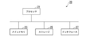
- FIG. 6 is a schematic block diagram showing the configuration of a computer according to at least one embodiment.
- Computer 20 includes processor 21 , main memory 23 , storage 25 and interface 27 .
- the data generation device 11 and model learning device 13 described above are implemented in the computer 20 .
- the operation of each processing unit described above is stored in the storage 25 in the form of a program.
- the processor 21 reads a program from the storage 25, develops it in the main memory 23, and executes the above processes according to the program.
- the processor 21 secures storage areas corresponding to the storage units described above in the main memory 23 according to the program. Examples of the processor 21 include a CPU (Central Processing Unit), a GPU (Graphic Processing Unit), a microprocessor, and the like.
- the program may be for realizing part of the functions to be exhibited by the computer 20.
- the program may function in combination with another program already stored in the storage or in combination with another program installed in another device.
- the computer 20 may include a custom LSI (Large Scale Integrated Circuit) such as a PLD (Programmable Logic Device) in addition to or instead of the above configuration.
- PLDs include PAL (Programmable Array Logic), GAL (Generic Array Logic), CPLD (Complex Programmable Logic Device), and FPGA (Field Programmable Gate Array).
- part or all of the functions implemented by processor 21 may be implemented by the integrated circuit.
- Such an integrated circuit is also included as an example of a processor.
- Examples of the storage 25 include magnetic disks, magneto-optical disks, optical disks, and semiconductor memories.
- the storage 25 may be an internal medium directly connected to the bus of the computer 20, or an external medium connected to the computer 20 via the interface 27 or communication line. Further, when this program is distributed to the computer 20 via a communication line, the computer 20 receiving the distribution may develop the program in the main memory 23 and execute the above process.
- storage 25 is a non-transitory, tangible storage medium.
- the program may be for realizing part of the functions described above.
- the program may be a so-called difference file (difference program) that implements the above-described functions in combination with another program already stored in the storage 25 .
- Data generation system 11 Data generation device 111... Model storage unit 112... Latent variable generation unit 113... Image generation unit 114... Three-dimensional data generation unit 115... Conversion unit 116... Output unit 13... Model learning device 131... For learning Data storage unit 132... Model storage unit 133... Latent variable generation unit 134... Image generation unit 135... Three-dimensional data generation unit 136... Conversion unit 137... Identification unit 138... Calculation unit 139... Update unit
Landscapes
- Engineering & Computer Science (AREA)
- Computer Vision & Pattern Recognition (AREA)
- Physics & Mathematics (AREA)
- General Physics & Mathematics (AREA)
- Theoretical Computer Science (AREA)
- Image Analysis (AREA)
Abstract
画像生成部は、潜在変数を機械学習モデルである画像生成モデルに入力することで、第1被写界深度に係る撮像画像を模擬した第1画像データを生成する。三次元データ生成部は、潜在変数を機械学習モデルである三次元生成モデルに入力することで、第1画像データに対応する三次元データを生成する。変換部は、第1画像データと三次元データとに基づいて、第2被写界深度に係る撮像画像を模擬した第2画像データを生成する。算出部は、第1画像データおよび第2画像データの分布と、実際の撮像画像の経験分布との近さの度合いを示す学習基準値を算出する。更新部は、学習基準値に基づいて画像生成モデルおよび三次元生成モデルのパラメータを更新する。
Description
本発明は、学習装置、学習済みモデルの生成方法、データ生成装置、データ生成方法およびプログラムに関する。
二次元の画像データから、その画像データに対応する三次元データ(深度情報など)を推定することは、長く関心を集めている問題の一つである。この問題を解くための方法として、二次元画像と三次元データのペアデータを教師データとして、二次元画像から三次元データを得る変換器を学習する方法が知られている。しかし、ペアデータを集めるためには専用の機器が必要であり、さらにデータ取得後もデータ間のアライメントを正確に取ることが必要であるため、データ収集コストが高いという問題がある。
非特許文献1には、生成モデルによって視点の異なる画像データを、生成される画像データの経験分布が実画像の経験分布と一致するように学習する技術が開示されている。
A. Noguchi, T. Harada, "RGBD-GAN: Unsupervised 3D Representation Learning From Natural Image Datasets via RGBD Image Synthesis," in Proc. ICLR 2020.
しかしながら、非特許文献1に記載の技術を実現するためには、学習に用いるデータセットに、複数の異なる視点から撮像された画像データが十分な量含まれている必要がある。そのため、異なる視点に係る画像データを収集することが困難な場合に、適切な学習を行うことができない可能性がある。
本発明の目的は、三次元データに関する補足データなしに、二次元画像と、当該二次元画像に対応する三次元データとを生成することができる学習装置、学習済みモデルの生成方法、データ生成装置、データ生成方法およびプログラムを提供することにある。
本発明の目的は、三次元データに関する補足データなしに、二次元画像と、当該二次元画像に対応する三次元データとを生成することができる学習装置、学習済みモデルの生成方法、データ生成装置、データ生成方法およびプログラムを提供することにある。
本発明の一態様は、潜在変数を機械学習モデルである画像生成モデルに入力することで、第1被写界深度に係る撮像画像を模擬した第1画像データを生成する画像生成部と、前記潜在変数を機械学習モデルである三次元生成モデルに入力することで、前記第1画像データに対応する三次元データを生成する三次元データ生成部と、前記第1画像データと前記三次元データとに基づいて、第2被写界深度に係る撮像画像を模擬した第2画像データを生成する変換部と、前記第1画像データおよび前記第2画像データの分布と、実際の撮像画像の経験分布との近さの度合いを示す学習基準値を算出する算出部と、前記学習基準値に基づいて前記画像生成モデルおよび前記三次元生成モデルのパラメータを更新する更新部とを備える学習装置である。
本発明の一態様は、潜在変数を機械学習モデルである画像生成モデルに入力することで、第1被写界深度に係る撮像画像を模擬した第1画像データを生成するステップと、前記潜在変数を機械学習モデルである三次元生成モデルに入力することで、前記第1画像データに対応する三次元データを生成するステップと、前記第1画像データと前記三次元データとに基づいて、第2被写界深度に係る撮像画像を模擬した第2画像データを生成するステップと、前記第1画像データおよび前記第2画像データの分布と、実際の撮像画像の経験分布との近さの度合いを示す学習基準値を算出するステップと、前記学習基準値に基づいて前記画像生成モデルおよび前記三次元生成モデルのパラメータを更新するステップと、学習済みの前記画像生成モデルおよび前記三次元生成モデルを出力するステップとを有する学習済みモデルの生成方法である。
本発明の一態様は、上記態様に係る学習済みモデルの生成方法によって出力された画像生成モデルに潜在変数を入力することで、撮像画像を模擬した画像データを生成する画像生成部と、上記態様に係る学習済みモデルの生成方法によって出力された三次元生成モデルに前記潜在変数を入力することで、三次元データを生成する三次元データ生成部と、を備えるデータ生成装置である。
本発明の一態様は、上記態様に係る学習済みモデルの生成方法によって出力された画像生成モデルに潜在変数を入力することで、撮像画像を模擬した画像データを生成するステップと、上記態様に係る学習済みモデルの生成方法によって出力された三次元生成モデルに前記潜在変数を入力することで、三次元データを生成するステップと、を備えるデータ生成方法である。
本発明の一態様は、コンピュータを、上記態様に係る学習装置として機能させるためのプログラムである。
上記少なくとも1つの態様によれば、三次元データに関する補足データなしに、二次元画像と、当該二次元画像に対応する三次元データとを生成することができる。
〈第1の実施形態〉
《データ生成システム1の構成》
図1は、第1の実施形態に係るデータ生成システム1の構成を示す図である。データ生成システム1は、同一の被写体に係る被写界深度の深い撮像画像を模擬した画像データ(ディープデプスオブフィールドイメージ)、被写界深度の浅い撮像画像を模擬した画像データ(シャローデプスオブフィールドイメージ)、および被写体の深度を示す深度データを生成する。ディープデプスオブフィールドイメージは、ピントが合っているように見える範囲が広い画像データである。シャロ―デプスオブフィールドイメージは、ピントが合っているように見える範囲が狭い画像データである。
《データ生成システム1の構成》
図1は、第1の実施形態に係るデータ生成システム1の構成を示す図である。データ生成システム1は、同一の被写体に係る被写界深度の深い撮像画像を模擬した画像データ(ディープデプスオブフィールドイメージ)、被写界深度の浅い撮像画像を模擬した画像データ(シャローデプスオブフィールドイメージ)、および被写体の深度を示す深度データを生成する。ディープデプスオブフィールドイメージは、ピントが合っているように見える範囲が広い画像データである。シャロ―デプスオブフィールドイメージは、ピントが合っているように見える範囲が狭い画像データである。
データ生成システム1は、データ生成装置11とモデル学習装置13とを備える。
データ生成装置11は、機械学習モデルである画像生成モデルおよび三次元生成モデルを用いて、ディープデプスオブフィールドイメージ、シャローデプスオブフィールドイメージおよび深度データの組を生成する。
モデル学習装置13は、実際の撮像画像を学習用データとして用いて画像生成モデルおよび三次元生成モデルの学習を行う。なお、学習用データに係る撮像画像は、三次元データに関する補足データを有する必要はない。つまり、学習用データは深度データなどの三次元データや、視点を異ならせた撮像画像のペアなどを含まなくてもよい。
データ生成装置11は、機械学習モデルである画像生成モデルおよび三次元生成モデルを用いて、ディープデプスオブフィールドイメージ、シャローデプスオブフィールドイメージおよび深度データの組を生成する。
モデル学習装置13は、実際の撮像画像を学習用データとして用いて画像生成モデルおよび三次元生成モデルの学習を行う。なお、学習用データに係る撮像画像は、三次元データに関する補足データを有する必要はない。つまり、学習用データは深度データなどの三次元データや、視点を異ならせた撮像画像のペアなどを含まなくてもよい。
《モデル学習装置13の構成》
図2は、第1の実施形態に係るモデル学習装置13の構成を示す概略ブロック図である。第1の実施形態に係るモデル学習装置13は、学習用データ記憶部131、モデル記憶部132、潜在変数生成部133、画像生成部134、三次元データ生成部135、変換部136、識別部137、算出部138、更新部139を備える。
図2は、第1の実施形態に係るモデル学習装置13の構成を示す概略ブロック図である。第1の実施形態に係るモデル学習装置13は、学習用データ記憶部131、モデル記憶部132、潜在変数生成部133、画像生成部134、三次元データ生成部135、変換部136、識別部137、算出部138、更新部139を備える。
学習用データ記憶部131は、複数の画像データを記憶する。各画像データは、撮像装置によって撮像された画像である。学習用データ記憶部131は、様々な被写界深度に係る画像データを記憶する。
モデル記憶部132は、画像生成モデルGI、深度生成モデルGD、識別モデルC、および被写界深度効果レンダラRを記憶する。画像生成モデルGI、深度生成モデルGDおよび識別モデルCは、いずれもニューラルネットワーク(例えば、畳み込みニューラルネットワーク、全結合ニューラルネットワーク、再帰ニューラルネットワークなど)によって構成される。被写界深度効果レンダラRは、撮像装置の光学系を模擬する数理モデルによって構成される。
画像生成モデルGIは、潜在変数zを入力とし、被写界深度の深い撮像画像を模擬した画像データであるディープデプスオブフィールドイメージIg
dを出力とする。潜在変数は、画像データを生成するシードとなる任意の数値である。
深度生成モデルGDは、潜在変数zを入力とし、ディープデプスオブフィールドイメージIg
dの被写体の深度を表す深度データDgを出力とする。深度データDgの要素数はディープデプスオブフィールドイメージIg
dの要素数と等しい。画像生成モデルGIと深度生成モデルGDとは、一部の層(例えば、入力層および中間層)を共通とするものであってよい。
被写界深度効果レンダラRは、ディープデプスオブフィールドイメージIg
dと深度データDgの組を入力とし、ディープデプスオブフィールドイメージIg
dと同じ被写体に係る被写界深度の浅い撮像画像を模擬した画像データであるシャローデプスオブフィールドイメージIg
sを出力とする。被写界深度効果レンダラRの詳細については後述する。
識別モデルCは、画像データを入力とし、入力された画像データが実際の撮像画像である確率または実際の撮像画像である度合を示す評価値を出力とする。例えば、識別モデルCは、実際の撮像画像である確率を出力する場合、入力された画像データがディープデプスオブフィールドイメージIg
dまたはシャローデプスオブフィールドイメージIg
sである確率が高いほど0に近い値を出力し、実際の撮像データである確率が高いほど1に近い値を出力する。
画像生成モデルGI、深度生成モデルGD、識別モデルCおよび被写界深度効果レンダラRは、GANs(Generative Adversarial Networks)を構成する。画像生成モデルGI、深度生成モデルGDおよび被写界深度効果レンダラRの組み合わせは、Generatorである。識別モデルCは、Discriminatorである。
潜在変数生成部133は、乱数に基づいて潜在変数zを生成する。例えば、潜在変数生成部133は、ガウシアン分布や一様分布などの任意の分布において、ランダムに潜在変数zを抽出する。なお、潜在変数生成部133は、学習用データ記憶部131が記憶する画像データから潜在変数zを抽出してもよい。
画像生成部134は、潜在変数生成部133が生成した潜在変数zをモデル記憶部132が記憶する画像生成モデルGIに入力することで、ディープデプスオブフィールドイメージIg
dを生成する。つまり、画像生成部134は、以下の式(1)によりディープデプスオブフィールドイメージIg
dを算出する。

三次元データ生成部135は、潜在変数生成部133が生成した潜在変数zをモデル記憶部132が記憶する深度生成モデルGDに入力することで、三次元データである深度データDgを生成する。つまり、三次元データ生成部135は、以下の式(2)により深度データDgを算出する。

変換部136は、画像生成部134が生成したディープデプスオブフィールドイメージIg
dと三次元データ生成部135が生成した深度データDgとをモデル記憶部132が記憶する被写界深度効果レンダラRに入力することで、シャローデプスオブフィールドイメージIg
sを生成する。つまり、変換部136は、ディープデプスオブフィールドイメージIg
dをシャローデプスオブフィールドイメージIg
sに変換する。つまり、変換部136は、以下の式(3)によりシャローデプスオブフィールドイメージIg
sを生成する。式(3)においてsは、ディープデプスオブフィールドイメージIg
dとシャローデプスオブフィールドイメージIg
sの混合度、すなわち被写界深度の深さの度合いを表す。なお、混合度sが0である場合、計算結果はディープデプスオブフィールドイメージIg
dと等しくなる。

ここで、被写界深度効果レンダラRについて説明する。第1の実施形態に係る被写界深度効果レンダラRは、仮想の光学系における光線の経路を計算し、仮想の光学系における開口面積を広げることで被写界深度の変換を行う。具体的には、被写界深度効果レンダラRは、深度データDgを変形関数Tを用いて変形することで、式(4)に示すように画像面上の位置座標xおよび開口面上の角度座標uと被写体の深度の関係を示す深度マップMg(x,u)を演算する。次に被写界深度効果レンダラRは、深度マップMg(x,u)に基づいて、式(5)に示すようにディープデプスオブフィールドイメージIg
dから、開口面上の視線方向ごとに入射する光によって結像される画像Lg(x,u)を演算する。そして、被写界深度効果レンダラRは、式(6)に示すように光学系の開口を模擬するインディケータA(u)を用いて画像Lg(x,u)を統合することで、シャローデプスオブフィールドイメージIg
sを生成する。



式(5)におけるm(hat)は、ピント位置までの距離(過焦点距離)を示す。m(hat)は、学習によって獲得される値であってもよいし、所定の分布から抽出される乱数であってもよいし、定数(例えばゼロ)であってもよい。
インディケータA(u)は、開口部に相当する要素の値が正値で、開口部以外の要素の値が0であり、すべての要素の値の和が1となる行列である。インディケータA(u)が模擬する開口部の形状は例えば円形である。このように、被写界深度効果レンダラRには、光線空間を考慮した光学的な制約が与えられている。これにより、被写界深度効果レンダラRは、光学的に整合性のとれた画像変換を実現することができる。
インディケータA(u)は、開口部に相当する要素の値が正値で、開口部以外の要素の値が0であり、すべての要素の値の和が1となる行列である。インディケータA(u)が模擬する開口部の形状は例えば円形である。このように、被写界深度効果レンダラRには、光線空間を考慮した光学的な制約が与えられている。これにより、被写界深度効果レンダラRは、光学的に整合性のとれた画像変換を実現することができる。
なお、被写界深度効果レンダラRは、深度データDg(x)に基づくワーピング関数(変形関数)によって構成されてもよいし、ニューラルネットワークモデルによって構成されてもよい。被写界深度効果レンダラRがニューラルネットワークモデルを構成に含む場合、ワーピング関数による変形結果に基づく制約を与えられてもよい。具体的には、被写界深度効果レンダラRは、ワーピング関数によって変形された深度データDgをニューラルネットワークモデルに入力するように構成されてもよい。
識別部137は、ディープデプスオブフィールドイメージIg
d、シャローデプスオブフィールドイメージIg
sおよび学習用データ記憶部131が記憶する撮像画像を識別モデルCに入力することで、入力された画像データが実際の撮像画像である度合を示す評価値を算出する。
算出部138は、画像生成モデルGI、深度生成モデルGDおよび識別モデルCの学習に用いる学習基準(損失関数)を算出する。具体的には、算出部138は、敵対的学習基準に基づいて学習基準を算出する。
敵対的学習基準LAR-GANとは、画像データが実際の撮像画像であるか撮像画像を模擬した画像データであるかの判断の正確さを示す指標である。算出部138は、以下の式(7)に示すように、敵対的学習基準LAR-GANを求める。
敵対的学習基準LAR-GANとは、画像データが実際の撮像画像であるか撮像画像を模擬した画像データであるかの判断の正確さを示す指標である。算出部138は、以下の式(7)に示すように、敵対的学習基準LAR-GANを求める。

式(7)において、s~Ps(s)は、ディープデプスオブフィールドイメージIg
dとシャローデプスオブフィールドイメージIg
sの混合度、すなわち被写界深度の深さの度合いを表す。分布Ps(s)は、0以上1以下の値域に係る分布、例えば二項分布や一様分布などを用いることができる。また、z~Pz(z)は、潜在変数zを分布Pz(z)から抽出する処理を示す。なお、式(7)では学習基準としてクロスエントロピーを用いるが、これに限られず、L1距離やL2距離、ワッサースタイン距離などの任意の距離基準に基づく学習基準を用いてもよい。
更新部139は、算出部138が算出した敵対的学習基準LAR-GANに基づいて画像生成モデルGI、深度生成モデルGDおよび識別モデルCのパラメータを更新する。具体的には、更新部139は、識別モデルCについて、敵対的学習基準LAR-GANが大きくなるようにパラメータを更新する。また更新部139は、画像生成モデルGIおよび深度生成モデルGDについて、敵対的学習基準LAR-GANが小さくなるようにパラメータを更新する。また、被写界深度効果レンダラRが学習可能なパラメータを持つ場合、被写界深度効果レンダラRについて、敵対的学習基準LAR-GANが小さくなるようにパラメータを更新する。
シャローデプスオブフィールドイメージIg
sは、光学的制約を有する被写界深度効果レンダラRを用いて、深度データDgから生成される。そのため、識別モデルCがシャローデプスオブフィールドイメージIg
sを実際の撮像画像であると誤判定させるためには、上記光学的制約の下、適切な深度データDgを生成する必要がある。したがって、第1の実施形態に係るモデル学習装置13は、上記の学習基準に従ってパラメータを更新することで、ディープデプスオブフィールドイメージIg
d、シャローデプスオブフィールドイメージIg
sおよび深度データDgの組が適切に生成できるように画像生成モデルGIおよび深度生成モデルGDのパラメータを更新することができる。また、被写界深度効果レンダラRが学習可能なパラメータを持つ場合、被写界深度効果レンダラRのパラメータを更新することができる。
《モデル学習装置13の動作》
図3は、第1の実施形態に係るモデル学習装置13の動作を示すフローチャートである。図4は、第1の実施形態に係る学習処理におけるデータの変遷を示す図である。
モデル学習装置13が学習処理を開始すると、以下に示すステップS1からステップS6の処理を、所定回数繰り返し実行する。まず潜在変数生成部133は、乱数と所定の分布とに基づいて潜在変数zを生成する(ステップS1)。次に、画像生成部134は、ステップS1で生成した潜在変数zをモデル記憶部132が記憶する画像生成モデルGIに入力することで、ディープデプスオブフィールドイメージIg dを生成する(ステップS2)。
図3は、第1の実施形態に係るモデル学習装置13の動作を示すフローチャートである。図4は、第1の実施形態に係る学習処理におけるデータの変遷を示す図である。
モデル学習装置13が学習処理を開始すると、以下に示すステップS1からステップS6の処理を、所定回数繰り返し実行する。まず潜在変数生成部133は、乱数と所定の分布とに基づいて潜在変数zを生成する(ステップS1)。次に、画像生成部134は、ステップS1で生成した潜在変数zをモデル記憶部132が記憶する画像生成モデルGIに入力することで、ディープデプスオブフィールドイメージIg dを生成する(ステップS2)。
また三次元データ生成部135は、ステップS1で生成した潜在変数zをモデル記憶部132が記憶する深度生成モデルGDに入力することで、深度データDgを生成する(ステップS3)。次に、変換部136は、0以上1以下の混合度sを所定の分布に従って決定する(ステップS4)。変換部136は、ステップS2で生成したディープデプスオブフィールドイメージIg
dと、ステップS3で生成した深度データDgに混合度sを乗算したものとを、モデル記憶部132が記憶する被写界深度効果レンダラRに入力することで、シャローデプスオブフィールドイメージIg
sを生成する(ステップS5)。なお、混合度sがゼロである場合、生成されるシャローデプスオブフィールドイメージIg
sはディープデプスオブフィールドイメージIg
dと一致する。次に、識別部137は、シャローデプスオブフィールドイメージIg
sを識別モデルCに入力することで、入力されたシャローデプスオブフィールドイメージIg
sが実際の撮像画像である度合を示す評価値を算出する(ステップS6)。
モデル学習装置13は、所定数の潜在変数zから生成されたシャローデプスオブフィールドイメージIg
sについての評価値を算出すると、以下に示すステップS7からステップS8の処理を所定回数繰り返し実行する。まず識別部137は、学習用データ記憶部131から任意の撮像画像を読み出す(ステップS7)。識別部137は、読み出した撮像画像を識別モデルCに入力することで、入力された撮像画像が実際の撮像画像である度合を示す評価値を算出する(ステップS8)。
算出部138は、ステップS6で算出した評価値およびステップS8で算出した評価値を用いて、上述の式(7)に基づいて敵対的学習基準LAR-GANを算出する(ステップS9)。更新部139は、ステップS9で算出した敵対的学習基準LAR-GANに基づいて画像生成モデルGI、深度生成モデルGDおよび識別モデルCのパラメータを更新する(ステップS10)。また、被写界深度効果レンダラRが学習可能なパラメータを持つ場合、被写界深度効果レンダラRのパラメータを更新する。
更新部139は、ステップS1からステップS10によるパラメータの更新を、所定のエポック数だけ繰り返し実行したか否かを判定する(ステップS11)。繰り返しが所定のエポック数に満たない場合(ステップS11:NO)、モデル学習装置13はステップS1に処理を戻し、学習処理を繰り返し実行する。
他方、繰り返しが所定のエポック数に達した場合(ステップS11:YES)、モデル学習装置13は学習処理を終了する。これにより、モデル学習装置13は、学習済みモデルである画像生成モデルGIおよび深度生成モデルGDを生成することができる。また、被写界深度効果レンダラRが学習可能なパラメータを持つ場合、学習済みモデルである被写界深度効果レンダラRを生成することができる。
《データ生成装置11の構成》
図5は、第1の実施形態に係るデータ生成装置11の構成を示す概略ブロック図である。
第1の実施形態に係るデータ生成装置11は、モデル記憶部111、潜在変数生成部112、画像生成部113、三次元データ生成部114、変換部115、出力部116を備える。
図5は、第1の実施形態に係るデータ生成装置11の構成を示す概略ブロック図である。
第1の実施形態に係るデータ生成装置11は、モデル記憶部111、潜在変数生成部112、画像生成部113、三次元データ生成部114、変換部115、出力部116を備える。
モデル記憶部111は、モデル学習装置13による学習済みの画像生成モデルGIおよび深度生成モデルGD、およびモデル学習装置13と同じ被写界深度効果レンダラRを記憶する。
潜在変数生成部112、画像生成部113、三次元データ生成部114および変換部115は、モデル学習装置13が備える、潜在変数生成部133、画像生成部134、三次元データ生成部135および変換部136と同様の処理を実行する。なお、変換部115は、シャローデプスオブフィールドイメージIg
sを生成する際、混合度sを1として計算する。
出力部116は、画像生成部113が生成したディープデプスオブフィールドイメージIg
d、三次元データ生成部114が生成した深度データDgおよび変換部115が生成したシャローデプスオブフィールドイメージIg
sを出力する。
《作用・効果》
これにより、データ生成装置11は、二次元画像であるディープデプスオブフィールドイメージIg dおよびシャローデプスオブフィールドイメージIg sと、三次元データである深度データDgとの組を生成することができる。データ生成装置11がこれらのデータの組を生成するために用いる画像生成モデルGIおよび深度生成モデルGDは、三次元データに関する補足データなしに学習されたものである。つまり、第1の実施形態に係るデータ生成システム1によれば、三次元データに関する補足データなしに、二次元画像と、当該二次元画像に対応する三次元データとを生成することができる。
これにより、データ生成装置11は、二次元画像であるディープデプスオブフィールドイメージIg dおよびシャローデプスオブフィールドイメージIg sと、三次元データである深度データDgとの組を生成することができる。データ生成装置11がこれらのデータの組を生成するために用いる画像生成モデルGIおよび深度生成モデルGDは、三次元データに関する補足データなしに学習されたものである。つまり、第1の実施形態に係るデータ生成システム1によれば、三次元データに関する補足データなしに、二次元画像と、当該二次元画像に対応する三次元データとを生成することができる。
これは、モデル学習装置13が、ディープデプスオブフィールドイメージIg
dの経験分布およびディープデプスオブフィールドイメージIg
dと深度データDgから生成されたシャローデプスオブフィールドイメージIg
sの経験分布が、いずれも実際の撮像画像の経験分布に近くなるようにモデルを学習させるためである。つまり、ディープデプスオブフィールドイメージIg
dと深度データDgから生成されたシャローデプスオブフィールドイメージIg
sが、実際の撮像画像の経験分布に近くなるためには、適切な深度データDgが得られている必要があり、シャローデプスオブフィールドイメージIg
sが、実際の撮像画像の経験分布に近くなったということは、モデルが適切な深度データDgを得ることができるように学習されたことを示すためである。
《実験結果》
第1の実施形態に係るデータ生成システム1を用いたデータペアの生成の実験結果の一例を説明する。実験では、学習用データとして花画像、鳥画像、顔画像に係る撮像画像が用いられた。
第1の実施形態に係るデータ生成システム1を用いたデータペアの生成の実験結果の一例を説明する。実験では、学習用データとして花画像、鳥画像、顔画像に係る撮像画像が用いられた。
実験では、データ生成システム1は正規分布N(0,1)に基づいてランダムに潜在変数zを抽出した。画像生成モデルGI、深度生成モデルGDおよび識別モデルCは、CNNによって構成した。被写体深度効果レンダラRの変形関数Tは、Dg(x)に基づいてワーピングを行った後、CNNを適用する構成を用いた。
実験において、非特許文献1に記載のRGBD-GANを比較例とした。
評価方法として、第1の実施形態に係るデータ生成システム1および非特許文献1の手法のそれぞれで生成されたデータペアを教師データとして用いた画像データから深度データへの変換器の精度を比較する方法を採用した。具体的には、第1の実施形態に係るデータ生成システム1および非特許文献1の手法のそれぞれで生成されたデータペアを教師データとして用いた変換器による計算結果と、実際の撮像画像と実際の深度データのペア(実ペアデータ)とを教師データとして用いた変換器による計算結果との一致度を比較した。評価尺度は、Scale-Invariant Depth Error(SIDE)を用いた。SIDEは、値が小さいほど性能がよいことを示す。
評価方法として、第1の実施形態に係るデータ生成システム1および非特許文献1の手法のそれぞれで生成されたデータペアを教師データとして用いた画像データから深度データへの変換器の精度を比較する方法を採用した。具体的には、第1の実施形態に係るデータ生成システム1および非特許文献1の手法のそれぞれで生成されたデータペアを教師データとして用いた変換器による計算結果と、実際の撮像画像と実際の深度データのペア(実ペアデータ)とを教師データとして用いた変換器による計算結果との一致度を比較した。評価尺度は、Scale-Invariant Depth Error(SIDE)を用いた。SIDEは、値が小さいほど性能がよいことを示す。
その結果、第1の実施形態に係るデータ生成システム1が非特許文献1の手法よりもSIDEの値が小さいことを確認した。すなわち、第1の実施形態に係るデータ生成システム1が非特許文献1の手法よりも実ペアデータを用いて学習した変換結果との一致度が高いことを確認した。なお、非特許文献1の手法は、視点に関する手がかりを予め取得しておく必要があるのに対し、第1の実施形態に係るデータ生成システム1ではこのような情報が不要である。また、非特許文献1の手法は、画像データと深度データのペアを生成するのに対し、第1の実施形態に係るデータ生成システム1は、ディープデプスオブフィールドイメージIg
d、深度データDgおよびシャローデプスオブフィールドイメージIg
sの組を得ることができる。
〈第2の実施形態〉
第1の実施形態に係るデータ生成システム1は、光線空間に基づく光学的な制約を有する被写界深度効果レンダラRを用いてシャローデプスオブフィールドイメージIg sを生成する。これに対し、第2の実施形態に係るデータ生成システム1は、深度とボケ効果の大きさとの関係に基づく光学的な制約を有する被写界深度効果レンダラRを用いてシャローデプスオブフィールドイメージIg sを生成する。
第1の実施形態に係るデータ生成システム1は、光線空間に基づく光学的な制約を有する被写界深度効果レンダラRを用いてシャローデプスオブフィールドイメージIg sを生成する。これに対し、第2の実施形態に係るデータ生成システム1は、深度とボケ効果の大きさとの関係に基づく光学的な制約を有する被写界深度効果レンダラRを用いてシャローデプスオブフィールドイメージIg sを生成する。
第2の実施形態に係る被写界深度効果レンダラRは、以下の式(8)、(9)で表されるカーネルkを用いて計算を行う。


式(8)において,[・]はアイバーソンの記法を表し、括弧内の条件が真ならば1、偽ならば0をとる。mは、被写体の位置を基準としたピント位置の深度を示す。深度mがゼロであることは、被写体にフォーカスがあっていることを示す。深度mが正の値であることは、ピント位置が被写体より手前側に位置することを示す。深度mが負の値であることは、ピント位置が被写体より奥側に位置することを示す。この定義により,k(hat)(x,m)は,半径|m|以内の中央部のみ値1を持ち,それ以外は値0を持つ。つまり、深度|m|が大きければ大きいほど、中央の円形部の大きさは大きくなり、このカーネルを画像に畳み込んだ時のボケ効果は大きくなる。また式(9)は、k(x,m)の要素の値の合計が1となるようにk(hat)(x,m)を正規化する処理を表す式である。
また、第2の実施形態では、三次元データ生成部135は、Dgを算出する前段階として、三次元データ生成部135は、深度情報の確率分布P(x,m)を生成する。ここで、P(x,m)は位置座標xの深度mにおける深度の存在確率を表す。つまり、各座標xについて存在確率P(x,m)の総和は1となる。P(x,m)が得られたとき,Dg(x)は、例えば式(10)に示すように、P(x,m)に対して,各座標xごとに最大となる深度mを算出することによって求めることが可能である。

三次元データ生成部135は、式(10)の演算を行う際、前処理として、P(x,m)に対してスムージングなどを行なってもよい。そして、変換部136は、以下の式(11)にように、カーネルk(x,m)とディープデプスオブフィールドイメージIg
dとを畳み込んだ結果と、深度データの確率分布P(x,m)とを乗算し、その和をとることによりシャローデプスオブフィールドイメージIg
sを合成することができる。

式(11)において演算子*は畳み込み演算を表す。このように、第2の実施形態に係る被写界深度効果レンダラRを用いた演算は、形状が事前に定められたカーネルkとの畳み込みと、その重み付き和とに制約される。これにより、変換部136は、第1の実施形態と同様に、光学的に整合性のとれた変換を実現することができ、変換の過程において画像の内容を大きく棄損することなくボケ度合だけを変えることができる。
また、第1の実施形態に係るデータ生成システム1では、式(3)において、深度データに混合度sを乗算することによって被写界深度の度合いを調整するが、第2の実施形態に係るデータ生成システム2においては、式(11)において、k(x,m)のmに混合度sを乗算する(つまり、k(x,s・m)とする)ことによって、被写界深度の度合いを調整することが可能である。例えば、sが0の場合、k(x,m)は中心のみが1で、それ以外は0のカーネルとなるため、式(11)の出力は、被写界深度の深い画像になる。
また、第1の実施形態に係るデータ生成システム1では、式(3)において、深度データに混合度sを乗算することによって被写界深度の度合いを調整するが、第2の実施形態に係るデータ生成システム2においては、式(11)において、k(x,m)のmに混合度sを乗算する(つまり、k(x,s・m)とする)ことによって、被写界深度の度合いを調整することが可能である。例えば、sが0の場合、k(x,m)は中心のみが1で、それ以外は0のカーネルとなるため、式(11)の出力は、被写界深度の深い画像になる。
〈第3の実施形態〉
画像におけるボケは、被写体がピント位置より手前側にある場合と、奥側にあるために発生している場合とのそれぞれにおいて発生する。一方で、画像データから、被写体が手前側に存在するためにボケが生じているか、奥側に存在するためにボケが生じているかを判断することは困難である。そこで、第3の実施形態に係るデータ生成システム1では、ピントが合う被写体(対象物)が画像の中心近傍に存在する可能性が高く、また対象物の近傍に写る被写体は背景であることが多いというヒューリスティックスに基づいて、モデルの更新に用いる目的関数を算出する。
画像におけるボケは、被写体がピント位置より手前側にある場合と、奥側にあるために発生している場合とのそれぞれにおいて発生する。一方で、画像データから、被写体が手前側に存在するためにボケが生じているか、奥側に存在するためにボケが生じているかを判断することは困難である。そこで、第3の実施形態に係るデータ生成システム1では、ピントが合う被写体(対象物)が画像の中心近傍に存在する可能性が高く、また対象物の近傍に写る被写体は背景であることが多いというヒューリスティックスに基づいて、モデルの更新に用いる目的関数を算出する。
第3の実施形態に係る算出部138は、式(7)に示す敵対的学習基準LAR-GANに加え、以下の式(12)、(13)で表される深度学習基準Lpを求める。


式(12)においてrは画像中心からの距離を示し、rthとgはそれぞれ対象物の大きさと深さを定めるハイパーパラメータである。式(12)に示す事前深度データDpは、半径rth以内はピント位置にあることを示し、中心からの距離がrthより遠いほど、ピント位置より奥側に位置することを示す。また式(13)においてλpは深度学習基準Lpの重みを表すハイパーパラメータである。深度学習基準Lpは、深度データDgと事前深度データDpとの距離がゼロに近いほど低くなる。つまり、深度学習基準Lpは、深度データDgのうち少なくともフォーカスされる可能性が高い部分と予め定めたピント位置に係る深度との距離がゼロに近いほど低くなる。なお、式(13)では学習基準としてL2距離に基づくものを用いるが、これに限られず、L1距離やワッサースタイン距離などの任意の距離基準に基づく学習基準を用いてもよい。
上記の例では、予め定めたピント位置での深度をゼロ、当該位置以外での深度を、ピント位置より奥側となるように予め定めた値としているが、これに限られない。例えば、ヒューリスティックスに基づいて、画像の一部または全体領域における各位置での深度を予め定めておくことができる場合、深度学習基準Lpは、各位置において深度データDgと当該予め定めた深度との距離がゼロに近いほど低くなるものであってよい。また、式(13)に示す深度学習基準Lpは、画像の全体領域について深度データDgが示す深度と予め定めた深度との距離を求めるが、これに限られない。例えば深度学習基準Lpは、深度データDgのうち半径rth以内の領域や、ヒューリスティックスに基づいてフォーカスされる可能性が高いと判定された領域など、深度データDgの一部領域のみにおける距離に基づいて計算されるものであってもよい。また例えば深度学習基準Lpは、深度データDgのうち半径rthより外側の領域や、ヒューリスティックスに基づいてフォーカスされる可能性が低いと判定された領域などにおける深度が、遠景または近景に係る予め定めた深度に近いほど低くなるものであってもよい。
更新部139は、敵対的学習基準LAR-GANと深度学習基準Lpの和に基づいて、深度生成モデルGDのパラメータを更新する。これにより、中心にフォーカスがあい、周囲が背景となる深度データDgが生成されることが促進される。なお、更新部139は、深度学習基準Lpを学習の全工程において用いてもよいし、学習の途中段階まで用いてもよい。更新部139は、深度学習基準Lpを所定のエポック数に至るまで用い、以降用いないようにすることで、実際の深度データと事前深度データDpとにギャップがあった場合のネガティブな効果を抑制することができる。
《変形例》
第3の実施形態に係るデータ生成システム1は、対象物が画像の中心近傍に存在する可能性が高く、また対象物の近傍に写る被写体は背景であることが多いというヒューリスティックスに基づいて、式(12)に基づいて事前深度データDpを算出するが、これに限られない。例えば、他の実施形態においては、対象物の近傍に写る被写体は前景であることが多いというヒューリスティックスに基づいて計算してもよいし、人の顔がフォーカスされる可能性が高いというヒューリスティックスに基づいて、パターンマッチング処理により検出された顔の位置に基づいて事前深度データDpを算出してもよい。また、rthおよびgをハイパーパラメータではなく学習により更新するパラメータとしてもよい。
第3の実施形態に係るデータ生成システム1は、対象物が画像の中心近傍に存在する可能性が高く、また対象物の近傍に写る被写体は背景であることが多いというヒューリスティックスに基づいて、式(12)に基づいて事前深度データDpを算出するが、これに限られない。例えば、他の実施形態においては、対象物の近傍に写る被写体は前景であることが多いというヒューリスティックスに基づいて計算してもよいし、人の顔がフォーカスされる可能性が高いというヒューリスティックスに基づいて、パターンマッチング処理により検出された顔の位置に基づいて事前深度データDpを算出してもよい。また、rthおよびgをハイパーパラメータではなく学習により更新するパラメータとしてもよい。
〈他の実施形態〉
以上、図面を参照して一実施形態について詳しく説明してきたが、具体的な構成は上述のものに限られることはなく、様々な設計変更等をすることが可能である。すなわち、他の実施形態においては、上述の処理の順序が適宜変更されてもよい。また、一部の処理が並列に実行されてもよい。
上述した実施形態に係るデータ生成システム1は、データ生成装置11とモデル学習装置13とを備えるが、単独のコンピュータによって構成されるものであってもよい。
以上、図面を参照して一実施形態について詳しく説明してきたが、具体的な構成は上述のものに限られることはなく、様々な設計変更等をすることが可能である。すなわち、他の実施形態においては、上述の処理の順序が適宜変更されてもよい。また、一部の処理が並列に実行されてもよい。
上述した実施形態に係るデータ生成システム1は、データ生成装置11とモデル学習装置13とを備えるが、単独のコンピュータによって構成されるものであってもよい。
上述した実施形態に係るデータ生成システム1は、GANsによって画像生成モデルGIおよび深度生成モデルGDのパラメータを更新するが、これに限られない。例えば、他の実施形態に係るデータ生成システム1は、Variational Autoencoder、Flow Model、Denoising Diffusion Probablistic Modelなどの任意の生成モデルにおける学習基準によって画像生成モデルGIおよび深度生成モデルGDのパラメータを更新してもよい。
また、上述の実施形態に係る被写界深度効果レンダラRは、光学系の制約を模擬する数理モデルであるが、これに限られない。例えば被写界深度効果レンダラRは、ニューラルネットワークによって構成された学習済みモデルであってもよい。また、光学系に関わるパラメータなど被写界深度効果レンダラRの一部のパラメータを学習パラメータとして持っていてもよい。また、被写界深度効果レンダラRが学習可能なパラメータを持つ場合、画像生成モデルGIおよび深度生成モデルGDと同時に学習してもよい。
また、上述の実施形態に係るデータ生成装置11は、ディープデプスオブフィールドイメージIg
d、シャローデプスオブフィールドイメージIg
sおよび深度データDgの組を出力するが、これに限られない。例えば、他の実施形態に係るデータ生成装置11は、ディープデプスオブフィールドイメージIg
dと深度データDgの組を出力し、シャローデプスオブフィールドイメージIg
sを出力しなくてもよい。また、他の実施形態に係るデータ生成装置11は、シャローデプスオブフィールドイメージIg
sと深度データDgの組を出力し、ディープデプスオブフィールドイメージIg
dを出力しなくてもよい。また、他の実施形態に係るデータ生成装置11は、ディープデプスオブフィールドイメージIg
dとシャローデプスオブフィールドイメージIg
sの組を出力し、深度データDgを出力しなくてもよい。また、他の実施形態に係るデータ生成装置11は、ディープデプスオブフィールドイメージIg
d、シャローデプスオブフィールドイメージIg
sおよび深度データDgの組の少なくとも一部を統合したデータを出力してもよい。例えばデータ生成装置11は、ディープデプスオブフィールドイメージIg
dと深度データDgを、深度情報を含む画像データとして出力してもよい。
〈コンピュータ構成〉
図6は、少なくとも1つの実施形態に係るコンピュータの構成を示す概略ブロック図である。
コンピュータ20は、プロセッサ21、メインメモリ23、ストレージ25、インタフェース27を備える。
上述のデータ生成装置11およびモデル学習装置13は、コンピュータ20に実装される。そして、上述した各処理部の動作は、プログラムの形式でストレージ25に記憶されている。プロセッサ21は、プログラムをストレージ25から読み出してメインメモリ23に展開し、当該プログラムに従って上記処理を実行する。また、プロセッサ21は、プログラムに従って、上述した各記憶部に対応する記憶領域をメインメモリ23に確保する。プロセッサ21の例としては、CPU(Central Processing Unit)、GPU(Graphic Processing Unit)、マイクロプロセッサなどが挙げられる。
図6は、少なくとも1つの実施形態に係るコンピュータの構成を示す概略ブロック図である。
コンピュータ20は、プロセッサ21、メインメモリ23、ストレージ25、インタフェース27を備える。
上述のデータ生成装置11およびモデル学習装置13は、コンピュータ20に実装される。そして、上述した各処理部の動作は、プログラムの形式でストレージ25に記憶されている。プロセッサ21は、プログラムをストレージ25から読み出してメインメモリ23に展開し、当該プログラムに従って上記処理を実行する。また、プロセッサ21は、プログラムに従って、上述した各記憶部に対応する記憶領域をメインメモリ23に確保する。プロセッサ21の例としては、CPU(Central Processing Unit)、GPU(Graphic Processing Unit)、マイクロプロセッサなどが挙げられる。
プログラムは、コンピュータ20に発揮させる機能の一部を実現するためのものであってもよい。例えば、プログラムは、ストレージに既に記憶されている他のプログラムとの組み合わせ、または他の装置に実装された他のプログラムとの組み合わせによって機能を発揮させるものであってもよい。なお、他の実施形態においては、コンピュータ20は、上記構成に加えて、または上記構成に代えてPLD(Programmable Logic Device)などのカスタムLSI(Large Scale Integrated Circuit)を備えてもよい。PLDの例としては、PAL(Programmable Array Logic)、GAL(Generic Array Logic)、CPLD(Complex Programmable Logic Device)、FPGA(Field Programmable Gate Array)が挙げられる。この場合、プロセッサ21によって実現される機能の一部または全部が当該集積回路によって実現されてよい。このような集積回路も、プロセッサの一例に含まれる。
ストレージ25の例としては、磁気ディスク、光磁気ディスク、光ディスク、半導体メモリ等が挙げられる。ストレージ25は、コンピュータ20のバスに直接接続された内部メディアであってもよいし、インタフェース27または通信回線を介してコンピュータ20に接続される外部メディアであってもよい。また、このプログラムが通信回線によってコンピュータ20に配信される場合、配信を受けたコンピュータ20が当該プログラムをメインメモリ23に展開し、上記処理を実行してもよい。少なくとも1つの実施形態において、ストレージ25は、一時的でない有形の記憶媒体である。
また、当該プログラムは、前述した機能の一部を実現するためのものであってもよい。さらに、当該プログラムは、前述した機能をストレージ25に既に記憶されている他のプログラムとの組み合わせで実現するもの、いわゆる差分ファイル(差分プログラム)であってもよい。
1…データ生成システム 11…データ生成装置 111…モデル記憶部 112…潜在変数生成部 113…画像生成部 114…三次元データ生成部 115…変換部 116…出力部 13…モデル学習装置 131…学習用データ記憶部 132…モデル記憶部 133…潜在変数生成部 134…画像生成部 135…三次元データ生成部 136…変換部 137…識別部 138…算出部 139…更新部
Claims (10)
- 潜在変数を機械学習モデルである画像生成モデルに入力することで、第1被写界深度に係る撮像画像を模擬した第1画像データを生成する画像生成部と、
前記潜在変数を機械学習モデルである三次元生成モデルに入力することで、前記第1画像データに対応する三次元データを生成する三次元データ生成部と、
前記第1画像データと前記三次元データとに基づいて、第2被写界深度に係る撮像画像を模擬した第2画像データを生成する変換部と、
前記第1画像データおよび前記第2画像データの分布と実際の撮像画像の経験分布との近さの度合いを示す学習基準値を算出する算出部と、
前記学習基準値に基づいて前記画像生成モデルおよび前記三次元生成モデルのパラメータを更新する更新部と
を備える学習装置。 - 前記第2被写界深度は、前記第1被写界深度より浅い
請求項1に記載の学習装置。 - 前記変換部は、前記第1画像データと前記三次元データとを光学系の制約を模擬する数理モデルに入力することで、前記第2画像データを生成する
請求項1または請求項2に記載の学習装置。 - 画像データを入力とし、前記画像データが実際の撮像画像であるか撮像画像を模擬した画像データであるかを判定する機械学習モデルである識別モデルに、前記第1画像データおよび前記第2画像データの少なくとも一方、並びに前記実際の撮像画像を入力し、入力された画像データを識別する識別部を備え、
前記学習基準値は、前記識別部による識別しにくさの度合いを示し、
前記更新部は、前記学習基準値に基づいてさらに前記識別モデルのパラメータを更新する
請求項1から請求項3の何れか1項に記載の学習装置。 - 前記学習基準値は、画像データの分布と実際の撮像画像の経験分布との近さの度合いを示す第1基準値と、前記三次元データのうち少なくとも一部に係る各位置と予め定めた深度との距離に係る第2基準値の和である
請求項1から請求項4の何れか1項に記載の学習装置。 - 前記三次元データは、過焦点距離を基準とした深度を表す深度データであって、
前記変換部は、前記三次元データまたは深度の大きさを表すパラメータに係数を乗算することで、前記第2被写界深度の深さを異ならせる
請求項1から請求項5の何れか1項に記載の学習装置。 - 潜在変数を機械学習モデルである画像生成モデルに入力することで、第1被写界深度に係る撮像画像を模擬した第1画像データを生成するステップと、
前記潜在変数を機械学習モデルである三次元生成モデルに入力することで、前記第1画像データに対応する三次元データを生成するステップと、
前記第1画像データと前記三次元データとに基づいて、第2被写界深度に係る撮像画像を模擬した第2画像データを生成するステップと、
前記第1画像データおよび前記第2画像データの分布と、実際の撮像画像の経験分布との近さの度合いを示す学習基準値を算出するステップと、
前記学習基準値に基づいて前記画像生成モデルおよび前記三次元生成モデルのパラメータを更新するステップと、
学習済みの前記画像生成モデルおよび前記三次元生成モデルを出力するステップと
を有する学習済みモデルの生成方法。 - 請求項7に記載の学習済みモデルの生成方法によって出力された画像生成モデルに潜在変数を入力することで、撮像画像を模擬した画像データを生成する画像生成部と、
請求項7に記載の学習済みモデルの生成方法によって出力された三次元生成モデルに前記潜在変数を入力することで、三次元データを生成する三次元データ生成部と、
を備えるデータ生成装置。 - 請求項7に記載の学習済みモデルの生成方法によって出力された画像生成モデルに潜在変数を入力することで、撮像画像を模擬した画像データを生成するステップと、
請求項7に記載の学習済みモデルの生成方法によって出力された三次元生成モデルに前記潜在変数を入力することで、三次元データを生成するステップと、
を備えるデータ生成方法。 - コンピュータを、請求項1から請求項6の何れか1項に記載の学習装置として機能させるためのプログラム。
Priority Applications (2)
| Application Number | Priority Date | Filing Date | Title |
|---|---|---|---|
| PCT/JP2021/019579 WO2022249232A1 (ja) | 2021-05-24 | 2021-05-24 | 学習装置、学習済みモデルの生成方法、データ生成装置、データ生成方法およびプログラム |
| JP2023523716A JP7598058B2 (ja) | 2021-05-24 | 2021-05-24 | 学習装置、学習済みモデルの生成方法、データ生成装置、データ生成方法およびプログラム |
Applications Claiming Priority (1)
| Application Number | Priority Date | Filing Date | Title |
|---|---|---|---|
| PCT/JP2021/019579 WO2022249232A1 (ja) | 2021-05-24 | 2021-05-24 | 学習装置、学習済みモデルの生成方法、データ生成装置、データ生成方法およびプログラム |
Publications (1)
| Publication Number | Publication Date |
|---|---|
| WO2022249232A1 true WO2022249232A1 (ja) | 2022-12-01 |
Family
ID=84229611
Family Applications (1)
| Application Number | Title | Priority Date | Filing Date |
|---|---|---|---|
| PCT/JP2021/019579 Ceased WO2022249232A1 (ja) | 2021-05-24 | 2021-05-24 | 学習装置、学習済みモデルの生成方法、データ生成装置、データ生成方法およびプログラム |
Country Status (2)
| Country | Link |
|---|---|
| JP (1) | JP7598058B2 (ja) |
| WO (1) | WO2022249232A1 (ja) |
Cited By (1)
| Publication number | Priority date | Publication date | Assignee | Title |
|---|---|---|---|---|
| JP7513928B1 (ja) | 2023-06-09 | 2024-07-10 | 株式会社プロテリアル | 予測装置、予測方法、及びプログラム |
Citations (1)
| Publication number | Priority date | Publication date | Assignee | Title |
|---|---|---|---|---|
| JP2020042818A (ja) * | 2018-09-07 | 2020-03-19 | バイドゥ オンライン ネットワーク テクノロジー (ベイジン) カンパニー リミテッド | 3次元データの生成方法、3次元データの生成装置、コンピュータ機器及びコンピュータ読み取り可能な記憶媒体 |
-
2021
- 2021-05-24 JP JP2023523716A patent/JP7598058B2/ja active Active
- 2021-05-24 WO PCT/JP2021/019579 patent/WO2022249232A1/ja not_active Ceased
Patent Citations (1)
| Publication number | Priority date | Publication date | Assignee | Title |
|---|---|---|---|---|
| JP2020042818A (ja) * | 2018-09-07 | 2020-03-19 | バイドゥ オンライン ネットワーク テクノロジー (ベイジン) カンパニー リミテッド | 3次元データの生成方法、3次元データの生成装置、コンピュータ機器及びコンピュータ読み取り可能な記憶媒体 |
Non-Patent Citations (1)
| Title |
|---|
| ATSUHIRO NOGUCHI; TATSUYA HARADA: "RGBD-GAN: Unsupervised 3D Representation Learning From Natural Image Datasets via RGBD Image Synthesis", ARXIV.ORG, 25 May 2020 (2020-05-25), XP081665412 * |
Cited By (2)
| Publication number | Priority date | Publication date | Assignee | Title |
|---|---|---|---|---|
| JP7513928B1 (ja) | 2023-06-09 | 2024-07-10 | 株式会社プロテリアル | 予測装置、予測方法、及びプログラム |
| JP2024176651A (ja) * | 2023-06-09 | 2024-12-19 | 株式会社プロテリアル | 予測装置、予測方法、及びプログラム |
Also Published As
| Publication number | Publication date |
|---|---|
| JP7598058B2 (ja) | 2024-12-11 |
| JPWO2022249232A1 (ja) | 2022-12-01 |
Similar Documents
| Publication | Publication Date | Title |
|---|---|---|
| US11232286B2 (en) | Method and apparatus for generating face rotation image | |
| CN114170290B (zh) | 图像的处理方法及相关设备 | |
| CN116385505B (zh) | 数据处理方法、装置、系统和存储介质 | |
| JP2023529527A (ja) | 点群データの生成方法及び装置 | |
| CN116310219B (zh) | 一种基于条件扩散模型的三维脚型生成方法 | |
| US20220392251A1 (en) | Method and apparatus for generating object model, electronic device and storage medium | |
| CN113888689A (zh) | 图像渲染模型训练、图像渲染方法及装置 | |
| CN114586078A (zh) | 手部姿态估计方法、装置、设备以及计算机存储介质 | |
| CN117372604B (zh) | 一种3d人脸模型生成方法、装置、设备及可读存储介质 | |
| CN112329662B (zh) | 基于无监督学习的多视角显著性估计方法 | |
| US20250225713A1 (en) | Electronic device and method for restoring scene image of target view | |
| CN103778598B (zh) | 视差图改善方法和装置 | |
| CN113034675A (zh) | 一种场景模型构建方法、智能终端及计算机可读存储介质 | |
| CN116310120A (zh) | 多视角三维重建方法、装置、设备及存储介质 | |
| CN116416376A (zh) | 一种三维头发的重建方法、系统、电子设备及存储介质 | |
| KR102277100B1 (ko) | 인공지능 및 딥러닝 기술을 이용한 랜덤위상을 갖는 홀로그램 생성방법 | |
| CN114782449A (zh) | 下肢x光影像中关键点提取方法、系统、设备及存储介质 | |
| CN117745933A (zh) | 一种基于扩散模型的三维点云生成方法 | |
| CN115147577A (zh) | Vr场景生成方法、装置、设备及存储介质 | |
| JP7598058B2 (ja) | 学習装置、学習済みモデルの生成方法、データ生成装置、データ生成方法およびプログラム | |
| CN116645300A (zh) | 一种简单透镜点扩散函数估计方法 | |
| CN113011446A (zh) | 一种基于多源异构数据学习的智能目标识别方法 | |
| CN109377447B (zh) | 一种基于杜鹃搜索算法的Contourlet变换图像融合方法 | |
| CN118521682A (zh) | 图像生成方法、口型驱动模型的训练方法、装置和设备 | |
| CN117437409A (zh) | 基于多视角声图的深度学习目标自动识别方法及系统 |
Legal Events
| Date | Code | Title | Description |
|---|---|---|---|
| 121 | Ep: the epo has been informed by wipo that ep was designated in this application |
Ref document number: 21942890 Country of ref document: EP Kind code of ref document: A1 |
|
| WWE | Wipo information: entry into national phase |
Ref document number: 2023523716 Country of ref document: JP |
|
| NENP | Non-entry into the national phase |
Ref country code: DE |
|
| 122 | Ep: pct application non-entry in european phase |
Ref document number: 21942890 Country of ref document: EP Kind code of ref document: A1 |