WO2022244252A1 - 光通信装置、および制御方法 - Google Patents
光通信装置、および制御方法 Download PDFInfo
- Publication number
- WO2022244252A1 WO2022244252A1 PCT/JP2021/019401 JP2021019401W WO2022244252A1 WO 2022244252 A1 WO2022244252 A1 WO 2022244252A1 JP 2021019401 W JP2021019401 W JP 2021019401W WO 2022244252 A1 WO2022244252 A1 WO 2022244252A1
- Authority
- WO
- WIPO (PCT)
- Prior art keywords
- control signal
- optical
- unit
- connection destination
- signal
- Prior art date
- Legal status (The legal status is an assumption and is not a legal conclusion. Google has not performed a legal analysis and makes no representation as to the accuracy of the status listed.)
- Ceased
Links
Images


Classifications
-
- H—ELECTRICITY
- H04—ELECTRIC COMMUNICATION TECHNIQUE
- H04B—TRANSMISSION
- H04B10/00—Transmission systems employing electromagnetic waves other than radio-waves, e.g. infrared, visible or ultraviolet light, or employing corpuscular radiation, e.g. quantum communication
- H04B10/50—Transmitters
- H04B10/516—Details of coding or modulation
-
- H—ELECTRICITY
- H04—ELECTRIC COMMUNICATION TECHNIQUE
- H04J—MULTIPLEX COMMUNICATION
- H04J3/00—Time-division multiplex systems
Definitions
- the present invention relates to the technology of optical communication devices and control methods.
- User devices are connected by optical fibers as shown in FIG. 7, and communication using optical signals is performed between optical transmitters and receivers mounted on the user devices.
- User equipment A in FIG. The user equipment B comprises a transmitter 2 , a receiver 2 , a control signal superimposing section 2 , a control signal extracting section 2 and a transmission/reception separator 2 .
- a main signal 1 is output from a transmitter 1, and a control signal 1 containing state information (wavelength, power, temperature, etc.) is superimposed in a control signal superimposing unit 1, and passed through a transmission/reception separator 1. output to the optical fiber.
- a control signal is superimposed as AMCC (Auxiliary Management and Control Channel) on a low frequency band that does not interfere with the main signal. This allows them to be treated as physically separate signals.
- AMCC Advanced Management and Control Channel
- User device B converts the received optical signal into an electrical signal using a PD (Photo Diode) or the like, separates it, and treats it as an individual electrical signal.
- User equipment B extracts control signal 1 at control signal extraction unit 2 from the signal received via transmission/reception separator 1 , and receives main signal 1 at receiver 2 . Communication from user equipment B to user equipment A is performed in a similar manner.
- PD Photo Diode
- the object of the present invention is to provide a technology that allows a new control signal to be superimposed on the main signal.
- a detection unit that detects the rise or fall of a control signal output from a user device to an optical communication path, and when the detection unit detects the rise or fall of the control signal and an optical modulator that superimposes a new control signal on a main signal.
- An aspect of the present invention includes a detection step in which a detection unit detects a rise or fall of a control signal output from a user device to an optical communication path;
- the control method includes a superimposition step of superimposing a new control signal on the main signal when a falling edge is detected.
- a new control signal can be superimposed on the main signal.
- FIG. 1 is a diagram showing a basic configuration of an optical communication device 10;
- FIG. FIG. 4 is a diagram showing an example of transmission of a main signal and a control signal;
- FIG. 4 is a diagram for explaining superimposition of control signals;
- 2 is a diagram showing a configuration example of a control signal superimposing section 200;
- FIG. 2 is a diagram showing a configuration example of an optical communication device 10-1;
- FIG. 2 is a diagram showing a configuration example of an optical communication device 10-2;
- FIG. 3 is a diagram showing a configuration example of an optical communication device 10-3;
- FIG. It is a figure which shows the conventional structural example.
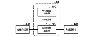
- FIG. 1 is a diagram showing the basic configuration of the optical communication device 10. As shown in FIG. The optical communication device 10 is connected to optical transceivers 300 and 400 via optical fibers (optical communication paths). The optical communication device 10 also includes a management control function unit 100 and a control signal superimposing unit 200 .
- the optical transceivers 300 and 400 are examples of user equipment.
- the optical transceivers 300 and 400 can transmit and receive a control signal including various setting parameters of the optical transceivers and user information superimposed on a main signal, which is a user signal.
- the optical transceivers 300 and 400 transmit and receive control signals as intermittent burst signals at regular intervals.
- the management control function unit 100 in the optical communication device 10 outputs a control signal to be superimposed on the main signal to the control signal superimposing unit 200 .
- the control signal superimposing unit 200 superimposes the control signal output by the management control function unit 100 between intermittent control signals transmitted from the optical transceiver 300 .
- FIG. 2A is a diagram showing an example of transmission of a main signal and a control signal.
- the horizontal axis indicates time.
- the control signal is transmitted as a burst signal.
- the control signal superimposing unit 200 superimposes the control signal output by the management control function unit 100 between the intermittent control signals transmitted from the optical transmitter/receiver 300 .
- the optical transmitter/receiver 400 on the receiving side performs processing in the same manner as a normal control signal. Also, when a signal is transmitted from the optical transmitter/receiver 400 to the optical transmitter/receiver 300, the control signal is similarly superimposed.
- intermittent burst signals are used as the control signal from the optical transmitter/receiver, and time division multiplexing (TDM) is applied to the control signal in the transmission line. It is possible to superimpose (modulate) various control signals.
- TDM time division multiplexing
- the interval between the intermittent control signals transmitted from the optical transceivers 300 and 400 may be a predetermined interval or an arbitrary interval.
- the control signal interval is set to an arbitrary interval, the maximum frame size of the control signal frame may be defined in advance and the interval may be longer than that.
- the interval may be determined according to the control signal superimposing section 200, as will be described later.
- FIG. 3 is a diagram showing a configuration example of the control signal superimposing section 200.
- the control signal superimposing section 200 is composed of a signal timing detector 210 and an optical modulator 220 .
- Signal timing detector 210 and optical modulator 220 can send and receive signals from each other.
- a wiring capable of transmitting/receiving electrical signals may be provided between the signal timing detector 210 and the optical modulator 220 .
- the signal timing detector 210 detects rising or falling of the control signal output from the optical transmitter/receiver 300 .
- the optical modulator 220 is a mechanism that can apply a signal input to the optical modulator as a modulation signal to the input light. (Electro-absorption type) modulator, SOA (Semiconductor optical amplifier) semiconductor optical amplifier, etc.
- the optical modulator 220 receives a new control signal from the management control function unit 100 and superimposes the new control signal. A new control signal to be superimposed is also expressed as a “new control signal”.
- feedforward control notifies the optical modulator 220 that the falling edge has been detected.
- the optical modulator 220 determines the start time of the non-signal section and superimposes the new control signal.
- the response time ⁇ of the control signal superimposing section 200 is defined as the time from when the signal timing detector 210 detects the falling edge to when the optical modulator 220 actually superimposes the new control signal.
- the control signals output from the optical transceivers 300 and 400 do not collide with the new control signal.
- the response time ⁇ which is the time from when the signal timing detector 210 detects the fall of the control signal to when the optical modulator 220 superimposes a new control signal, is is equal to or less than the time obtained by dividing the time obtained by subtracting the transmission time of the control signal from the interval of transmission of the control signal by 2.
- the transmission time here is the transmission time of the control signal having the largest size among the control signals.
- the interval for transmitting the control signal of the optical transceiver 300 can be set, by setting an interval greater than the time obtained by adding the transmission time of the control signal and twice ⁇ , the new control It can prevent signals from colliding.
- the signal timing detector 210 detects the falling edge of the control signal output from the optical transmitter/receiver 300, but the case of detecting the rising edge will be described.
- the frame size of the control signal frame is defined in advance, and the control signal interval is set to be equal to or longer than the time required to transmit the frame size ("T1").
- the signal timing detector 210 detects the rising edge, and the timing (referred to as "timing T2") after T1 has passed from that timing is the timing of the falling edge. Then, the control signal is not transmitted until at least time T1 elapses from timing T2.
- the optical modulator 220 uses the timing T2 as the falling edge detection timing, and superimposes the new control signal in the same manner as when the falling edge is detected. By doing so, even if the signal timing detector 210 detects the rising edge, the new control signal can be superimposed.
- FIG. 4 is a diagram showing a configuration example of an optical communication device 10-1 that is a first modification of the optical communication device 10. As shown in FIG.
- the optical communication device 10-1 in Modification 1 includes transmission/reception separation devices 500 and 600.
- the optical communication device 10-1 also includes two control signal superimposing units 200-1 and 200-2.
- the control signal superimposing units 200-1 and 200-2 each include the signal timing detector and optical modulator described with reference to FIG.
- the management control function unit 100 outputs new control signals to each of the control signal superimposing units 200-1 and 200-2.
- the new control signal superimposed by the control signal superimposing units 200-1 and 200-2 uses the same frequency as the control signal transmitted by the optical transceivers 300 and 400 or a frequency in a lower frequency region than the main signal as a pilot tone.
- a high frequency may be used as long as the optical transceivers 300 and 400 can separate the main signal and the control signal.
- the pilot tone may be a signal up-converted to a high frequency (for example, 500 kHz) at a level that does not affect the main signal, or may be a baseband-modulated signal.
- the optical transmitter/receiver 300 and the transmitter/receiver separating device 500 are connected by an optical fiber.
- the transmission/reception separation device 500 and the control signal superimposing unit 200-1 are connected by an optical fiber.
- the transmission/reception separation device 500 and the control signal superimposing unit 200-2 are connected by an optical fiber.
- the transmission/reception separation device 600 and the control signal superimposing unit 200-1 are connected by an optical fiber.
- the transmission/reception separation device 600 and the control signal superimposing unit 200-2 are connected by an optical fiber.
- the optical transmitter/receiver 400 and the transmitter/receiver separator 600 are connected by an optical fiber.
- the signal transmitted from the optical transmitter/receiver 300 is input to the control signal superimposing unit 200-1 via the transmitter/receiver separator 500, the new control signal is superimposed, and the signal is transmitted to the optical transmitter/receiver 400 via the transmitter/receiver separator 600. be.
- the signal transmitted from the optical transmitter/receiver 400 is input to the control signal superimposing unit 200-2 via the transmitter/receiver separator 600, and the new control signal is superimposed thereon. sent to.
- the control signal superimposing units 200-1 and 200-2 transmission of the control signal for setting the wavelength from the management control function unit 100 is realized even after the connection of the optical transceivers 300 and 400 is completed unlike the conventional art.
- an upstream signal optical modulation unit (control signal superimposing unit 200-1) superimposes a new control signal on the upstream signal as an optical modulation unit. 200-2) and a downstream signal optical modulator for superimposing a new control signal on the downstream signal (optical modulator provided in the control signal superimposing unit 200-2).
- FIG. 5 is a diagram showing a configuration example of an optical communication device 10-2, which is a modification 2 of the optical communication device 10.
- the optical communication device 10-2 in Modification 2 includes a switch 900-1 and an optical SW control function unit 700.
- FIG. Switch 900-1 connects subscriber devices 800-1, 800-2, and 800-3 with management control function unit 100 and control signal superimposing unit 200.
- FIG. Optical SW control function unit 700 controls switch 900-1.
- Control signal superimposing section 200 is connected to switch 900-2.
- Switch 900-2 connects with subscriber unit 800-4.
- the switch 900-1 and the control signal superimposing unit 200 are collectively referred to as GW1000-1.
- Switch 900-2 and subscriber unit 800-4 are collectively referred to as GW 1000-2.
- Subscriber units 800-1, 800-2, 800-3, 800-4 include the functionality included in optical transceivers 300, 400 described above.
- the management control function unit 100 is an example of a setting unit.
- Switch 900-1 is an example of a connection destination changing unit.
- the subscriber devices 800-1, 800-2, and 800-3 are each connected to the optical communication device 10-2 by optical fibers.
- the optical communication device 10-2 and GW 1000-2 are connected by an optical fiber.
- Subscriber unit 800-1 is first connected to management control function unit 100 via switch 900-1.
- management control function unit 100 sets a wavelength corresponding to a communication destination (service, user, etc.).
- the switch 900-1 switches the path under the control of the optical SW control function unit 700 (S1).
- subscriber unit 800-1 starts communication with a desired connection destination (subscriber unit 800-4 in the case of FIG. 5) via control signal superimposition section 200.
- FIG. 1 A desired connection destination (subscriber unit 800-4 in the case of FIG. 5) via control signal superimposition section 200.
- subscriber device 800-1 When subscriber device 800-1 connects to another subscriber device different from subscriber device 800-4 during communication between subscriber device 800-1 and subscriber device 800-4 (for example, subscriber device 800-1 sends a switching request), it is necessary to set the wavelength to be used in communication with other subscriber units.
- a branch unit for branching control signals exchanged between subscriber units is provided between switch 900-1 and control signal superimposing unit 200.
- FIG. Also, the optical communication device 10-2 is provided with a control TRx for receiving the signal branched from the branching unit.
- subscriber device 800-1 when subscriber device 800-1 switches communication destinations, subscriber device 800-1 transmits a disconnection request to subscriber device 800-4.
- the disconnection request is a signal indicating that the communication connection will be disconnected after this.
- the control TRx transmits ACK to the subscriber unit 800-1 in response to the connection disconnection request received by demodulating the control signal branched from the branching unit. Subscriber unit 800-1 stops emitting light to the communication path in response to transmission of the disconnection request. The light SW control function unit 700 recognizes that light emission has stopped.
- the subscriber unit 800-1 resumes emitting light to the communication path after a predetermined time has elapsed since the emission was stopped.
- optical SW control function unit 700 connects the input/output port in which light is detected to management control function unit 100 .
- Subscriber device 800 - 1 transmits a connection switching request to management control function unit 100 .
- the connection switching request includes information indicating the subscriber device that will become the new connection destination.
- management control function unit 100 Upon receiving the connection switching request, management control function unit 100 transmits ACK to subscriber device 800-1, which is the transmission source.
- the management control function unit 100 determines the wavelength and the like used in communication between the subscriber device 800-1 and the newly connected subscriber device.
- the management control function unit 100 sets the wavelength to be used in the control signal superimposition unit 200. , and the control signal superimposing unit 200 superimposes the signal for superimposition.
- a configuration using "control TRx" was described as an example of receiving a signal from subscriber unit 800-1.
- Rx The "control Rx” only needs to be able to receive low-speed signals using AMCC (Auxiliary Management and Control Channel), so even if it is not a main signal receiver (for example, a 10G (bit/second) class receiver) good.
- AMCC Advanced Management and Control Channel
- the subscriber device 800-1 receives the superimposed new control signal and sets the wavelength used in communication with other subscriber devices. After that, the switch 900-1 switches the path under the control of the optical SW control function unit 700 (S2).
- the control signal superimposing unit 200 allows the management control function unit 100 to transmit a control signal for managing wavelengths even after the subscriber device has completed communication with a desired connection destination.
- the connection destination may be switched by the management control function unit 100 due to failure of the optical communication path or various related devices.
- a control signal superimposing unit may be provided between the subscriber unit 800-1 and the connection destination switched by S2.
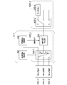
- FIG. 6 is a diagram showing a configuration example of an optical communication device 10-3, which is a third modified example of the optical communication device 10.
- the optical communication device 10-3 in Modification 3 includes a switch 900-1 and an optical SW control function unit 700.
- FIG. Furthermore, a control signal superimposing unit is provided for each subscriber unit.
- subscriber units 800-1, 800-2 and 800-3 are provided with control signal superimposing sections 200-1, 200-2 and 200-3, respectively.
- a subscriber device 800-1 is provided between the subscriber device 800-1 and the switch 900-3.
- Subscriber equipment 800-2 is provided between subscriber equipment 800-2 and switch 900-3.
- Subscriber equipment 800-3 is provided between subscriber equipment 800-3 and switch 900-3.
- Subscriber devices 800-1, 800-2, and 800-3 are each connected to optical communication device 10-2 via optical fibers.
- the control signal superimposing section 200 is connected to the control signal superimposing sections 200-1, 200-2 and 200-3.
- Control signal superimposing section 200 outputs a new control signal to each of control signal superimposing sections 200-1, 200-2, and 200-3.
- Subscriber unit 800-1 is first connected to management control function unit 100 through switch 900-3.
- management control function unit 100 sets a wavelength corresponding to a communication destination (service, user, etc.).
- the switch 900-3 switches the path under the control of the optical SW control function unit 700.
- subscriber unit 800-1 starts communication with a desired connection destination.
- management control is performed as in the second modification.
- the functional unit 100 outputs the new control signal to the control signal superimposing unit 200, and the control signal superimposing unit 200 superimposes the signal for superimposition.
- the management control function unit 100, the control signal superimposition units 200, 200-1, 200-2, and the optical SW control function unit 700 may be configured using a processor such as a CPU (Central Processing Unit) and a memory.
- management control function unit 100, control signal superimposition units 200, 200-1, 200-2, and optical SW control function unit 700 are controlled by processors executing respective programs. It functions as the signal superimposing units 200 , 200 - 1 and 200 - 2 and the optical SW control function unit 700 .
- each function of the management control function unit 100, the control signal superimposition units 200, 200-1, 200-2, and the optical SW control function unit 700 is implemented by ASIC (Application Specific Integrated Circuit) or PLD (Programmable Logic Device) or FPGA (Field Programmable Gate Array).
- the above program may be recorded on a computer-readable recording medium.
- Computer-readable recording media include portable media such as flexible disks, magneto-optical disks, ROMs, CD-ROMs, semiconductor storage devices (such as SSD: Solid State Drive), hard disks and semiconductor storage built into computer systems. It is a storage device such as a device.
- the above program may be transmitted via telecommunication lines.
- the present invention can be applied to optical communication devices that communicate with optical fibers.
- Optical communication device 100 Management control function unit 200, 200-1, 200-2, 200-3... Control signal superimposing unit 210... Signal timing detector 220... Light Modulators 300, 400... Optical transceivers 500, 600... Transmission/reception separation device 700... Control function units 800-1, 800-2, 800-3, 800-4... Subscriber units 900-1, 900-2, 900- 3... Switch
Landscapes
- Physics & Mathematics (AREA)
- Electromagnetism (AREA)
- Engineering & Computer Science (AREA)
- Computer Networks & Wireless Communication (AREA)
- Signal Processing (AREA)
- Optical Communication System (AREA)
Priority Applications (3)
| Application Number | Priority Date | Filing Date | Title |
|---|---|---|---|
| US18/561,416 US20240372625A1 (en) | 2021-05-21 | 2021-05-21 | Optical communication device and control method |
| PCT/JP2021/019401 WO2022244252A1 (ja) | 2021-05-21 | 2021-05-21 | 光通信装置、および制御方法 |
| JP2023522172A JP7617473B2 (ja) | 2021-05-21 | 2021-05-21 | 光通信装置、および制御方法 |
Applications Claiming Priority (1)
| Application Number | Priority Date | Filing Date | Title |
|---|---|---|---|
| PCT/JP2021/019401 WO2022244252A1 (ja) | 2021-05-21 | 2021-05-21 | 光通信装置、および制御方法 |
Publications (1)
| Publication Number | Publication Date |
|---|---|
| WO2022244252A1 true WO2022244252A1 (ja) | 2022-11-24 |
Family
ID=84140217
Family Applications (1)
| Application Number | Title | Priority Date | Filing Date |
|---|---|---|---|
| PCT/JP2021/019401 Ceased WO2022244252A1 (ja) | 2021-05-21 | 2021-05-21 | 光通信装置、および制御方法 |
Country Status (3)
| Country | Link |
|---|---|
| US (1) | US20240372625A1 (https=) |
| JP (1) | JP7617473B2 (https=) |
| WO (1) | WO2022244252A1 (https=) |
Cited By (1)
| Publication number | Priority date | Publication date | Assignee | Title |
|---|---|---|---|---|
| WO2024116323A1 (ja) * | 2022-11-30 | 2024-06-06 | 日本電信電話株式会社 | 制御装置、通信システム及び制御方法 |
Citations (3)
| Publication number | Priority date | Publication date | Assignee | Title |
|---|---|---|---|---|
| US6331792B1 (en) * | 2000-06-30 | 2001-12-18 | Conexant Systems, Inc. | Circuit and method for unlimited range frequency acquisition |
| JP2006197489A (ja) * | 2005-01-17 | 2006-07-27 | Nippon Telegr & Teleph Corp <Ntt> | 光波長多重システム、光終端装置および光ネットワークユニット |
| WO2020195912A1 (ja) * | 2019-03-26 | 2020-10-01 | 日本電信電話株式会社 | 光分岐挿入装置及び光分岐挿入装置を使用した光伝送システム |
-
2021
- 2021-05-21 US US18/561,416 patent/US20240372625A1/en active Pending
- 2021-05-21 JP JP2023522172A patent/JP7617473B2/ja active Active
- 2021-05-21 WO PCT/JP2021/019401 patent/WO2022244252A1/ja not_active Ceased
Patent Citations (3)
| Publication number | Priority date | Publication date | Assignee | Title |
|---|---|---|---|---|
| US6331792B1 (en) * | 2000-06-30 | 2001-12-18 | Conexant Systems, Inc. | Circuit and method for unlimited range frequency acquisition |
| JP2006197489A (ja) * | 2005-01-17 | 2006-07-27 | Nippon Telegr & Teleph Corp <Ntt> | 光波長多重システム、光終端装置および光ネットワークユニット |
| WO2020195912A1 (ja) * | 2019-03-26 | 2020-10-01 | 日本電信電話株式会社 | 光分岐挿入装置及び光分岐挿入装置を使用した光伝送システム |
Non-Patent Citations (1)
| Title |
|---|
| TANO, FUMIHIKO ET AL.: "Experimental investigation of an ONU registration control function by an automatic wavelength assignment using AMCC signals in 100 Gb/s coherent PON systems for 5G mobile convergence", IEICE TECHNICAL REPORT, vol. 116, no. 402 (OCS2016-66), 12 January 2017 (2017-01-12), pages 9 - 14, XP009541693, ISSN: 0913-5685 * |
Cited By (1)
| Publication number | Priority date | Publication date | Assignee | Title |
|---|---|---|---|---|
| WO2024116323A1 (ja) * | 2022-11-30 | 2024-06-06 | 日本電信電話株式会社 | 制御装置、通信システム及び制御方法 |
Also Published As
| Publication number | Publication date |
|---|---|
| US20240372625A1 (en) | 2024-11-07 |
| JPWO2022244252A1 (https=) | 2022-11-24 |
| JP7617473B2 (ja) | 2025-01-20 |
Similar Documents
| Publication | Publication Date | Title |
|---|---|---|
| JP5490517B2 (ja) | 光通信システム、光通信方法およびolt | |
| US7933518B2 (en) | Intelligent optical systems and methods for optical-layer management | |
| US8989591B2 (en) | Remote optical demarcation point | |
| CA2819857C (en) | Multiplex conversion for a passive optical network | |
| CN101997614B (zh) | 集成光收发器、光网络系统、光通信系统及方法 | |
| US9391693B2 (en) | Protection for distributed radio access networks | |
| US20230030158A1 (en) | Optical communication apparatus, optical communication system and optical communication method | |
| JP6690347B2 (ja) | 光通信システム、送信局及び光通信方法 | |
| JP5144609B2 (ja) | Ponシステムの局側終端装置 | |
| US12401423B2 (en) | Optical network, network management device, and network management method | |
| JP5137906B2 (ja) | 光アクセス網、光加入者装置および光アクセス網の通信設定方法 | |
| US20150222385A1 (en) | Transponder for wdm ring network | |
| US20230208522A1 (en) | Communication system and method, and related device | |
| CN101873513A (zh) | 集成光收发器以及光通信系统、方法 | |
| JP7617473B2 (ja) | 光通信装置、および制御方法 | |
| JP2005286803A (ja) | スター型光ネットワークにおける加入者端局装置及び異常光検出遮断装置 | |
| US12328537B2 (en) | Optical communication apparatus, optical communication system and optical communication method | |
| US8355631B2 (en) | Reducing optical service channel interference in phase modulated wavelength division multiplexed (WDM) communication systems | |
| JP2015173384A (ja) | 通信システム、加入者側装置、局側装置および無瞬断切替方法 | |
| JPWO2003105496A1 (ja) | 波長分割多重光信号の切り替え制御装置 | |
| JP6178264B2 (ja) | 波長監視方法、波長監視システム及び親ノード | |
| JP6107269B2 (ja) | トランスポンダ及び光伝送装置 | |
| JP5748372B1 (ja) | 波長監視方法、波長監視システム、親ノード及び子ノード | |
| US20240276128A1 (en) | Communication method and communication system | |
| Chand et al. | Optical LAN for avionics platforms |
Legal Events
| Date | Code | Title | Description |
|---|---|---|---|
| 121 | Ep: the epo has been informed by wipo that ep was designated in this application |
Ref document number: 21940864 Country of ref document: EP Kind code of ref document: A1 |
|
| WWE | Wipo information: entry into national phase |
Ref document number: 2023522172 Country of ref document: JP |
|
| NENP | Non-entry into the national phase |
Ref country code: DE |
|
| 122 | Ep: pct application non-entry in european phase |
Ref document number: 21940864 Country of ref document: EP Kind code of ref document: A1 |