WO2022239573A1 - 画像処理装置、画像処理方法、及び画像処理プログラム - Google Patents
画像処理装置、画像処理方法、及び画像処理プログラム Download PDFInfo
- Publication number
- WO2022239573A1 WO2022239573A1 PCT/JP2022/016570 JP2022016570W WO2022239573A1 WO 2022239573 A1 WO2022239573 A1 WO 2022239573A1 JP 2022016570 W JP2022016570 W JP 2022016570W WO 2022239573 A1 WO2022239573 A1 WO 2022239573A1
- Authority
- WO
- WIPO (PCT)
- Prior art keywords
- image
- reference point
- reference points
- image processing
- processor
- Prior art date
- Legal status (The legal status is an assumption and is not a legal conclusion. Google has not performed a legal analysis and makes no representation as to the accuracy of the status listed.)
- Ceased
Links
Images











Classifications
-
- G—PHYSICS
- G06—COMPUTING OR CALCULATING; COUNTING
- G06T—IMAGE DATA PROCESSING OR GENERATION, IN GENERAL
- G06T7/00—Image analysis
- G06T7/50—Depth or shape recovery
- G06T7/55—Depth or shape recovery from multiple images
-
- G—PHYSICS
- G06—COMPUTING OR CALCULATING; COUNTING
- G06T—IMAGE DATA PROCESSING OR GENERATION, IN GENERAL
- G06T7/00—Image analysis
- G06T7/50—Depth or shape recovery
-
- G—PHYSICS
- G01—MEASURING; TESTING
- G01B—MEASURING LENGTH, THICKNESS OR SIMILAR LINEAR DIMENSIONS; MEASURING ANGLES; MEASURING AREAS; MEASURING IRREGULARITIES OF SURFACES OR CONTOURS
- G01B11/00—Measuring arrangements characterised by the use of optical techniques
- G01B11/16—Measuring arrangements characterised by the use of optical techniques for measuring the deformation in a solid, e.g. optical strain gauge
-
- G—PHYSICS
- G01—MEASURING; TESTING
- G01N—INVESTIGATING OR ANALYSING MATERIALS BY DETERMINING THEIR CHEMICAL OR PHYSICAL PROPERTIES
- G01N21/00—Investigating or analysing materials by the use of optical means, i.e. using sub-millimetre waves, infrared, visible or ultraviolet light
- G01N21/84—Systems specially adapted for particular applications
- G01N21/88—Investigating the presence of flaws or contamination
-
- G—PHYSICS
- G06—COMPUTING OR CALCULATING; COUNTING
- G06T—IMAGE DATA PROCESSING OR GENERATION, IN GENERAL
- G06T7/00—Image analysis
- G06T7/70—Determining position or orientation of objects or cameras
- G06T7/73—Determining position or orientation of objects or cameras using feature-based methods
-
- G—PHYSICS
- G06—COMPUTING OR CALCULATING; COUNTING
- G06T—IMAGE DATA PROCESSING OR GENERATION, IN GENERAL
- G06T2207/00—Indexing scheme for image analysis or image enhancement
- G06T2207/10—Image acquisition modality
- G06T2207/10004—Still image; Photographic image
- G06T2207/10012—Stereo images
-
- G—PHYSICS
- G06—COMPUTING OR CALCULATING; COUNTING
- G06T—IMAGE DATA PROCESSING OR GENERATION, IN GENERAL
- G06T2207/00—Indexing scheme for image analysis or image enhancement
- G06T2207/10—Image acquisition modality
- G06T2207/10048—Infrared image
-
- G—PHYSICS
- G06—COMPUTING OR CALCULATING; COUNTING
- G06T—IMAGE DATA PROCESSING OR GENERATION, IN GENERAL
- G06T2207/00—Indexing scheme for image analysis or image enhancement
- G06T2207/30—Subject of image; Context of image processing
- G06T2207/30181—Earth observation
- G06T2207/30184—Infrastructure
Definitions
- the present invention relates to an image processing device, an image processing method, and an image processing program, and more particularly to a technique for aligning a plurality of images.
- a method of acquiring an image of a structure and diagnosing the structure based on this image has been proposed.
- a method of acquiring a visible image of a structure for diagnosis and a method of acquiring an infrared image for diagnosis have been proposed.
- Visible images can be used to detect surface defects such as cracks and spalling in structures such as concrete, mortar, and tiles, and infrared images can be used to detect internal defects such as floats.
- Methods for acquiring both visible and infrared images for diagnosis have also been proposed. For example, in Patent Document 1, visible image data and infrared image data of a structure are acquired using a normal camera and an infrared camera, and these image data are superimposed to form a hybrid image. A method for diagnosing structures with hybrid images is described.
- Patent Document 1 When making a diagnosis based on both a visible image and an infrared image, the visible image and the infrared image are often superimposed as in Patent Document 1 above. There is a deviation in the position of each point on the object reflected in . Specifically, since a normal camera and an infrared camera do not have the same angle of view, imaging position, etc., there is a difference in the position of each point on the object captured by each camera in each image. . To solve this problem, the above-mentioned Patent Document 1 describes deformation correction and necessary correction for the visible image and the infrared image so that the positions of the reference points on the object imaged on the visible image and the infrared image match.
- the scale correction is performed according to the However, even if the images are geometrically corrected so that the positions of the reference points match, the positions of the points other than the reference points on the visible image and the infrared image do not necessarily match. In other words, the positional deviation between the visible image and the infrared image is not always eliminated.
- the performance of diagnosing internal defects such as floats can be improved by using visible images at the same time. discrimination and reduction of false positives (discrimination)).
- discrimination and reduction of false positives discrimination
- a problem may arise in terms of improving the performance by using the visible image as described above.
- an image processing apparatus is an image processing apparatus comprising a processor, wherein the processor captures a first image and a first image of the same object from different positions. Acquiring a first image and a second image, which are two images, which are two-dimensional images captured in different wavelength bands, acquiring information indicating the position of a reference point on the surface of the object, and acquiring the acquired first image , the second image, and the information, the values of the first image corresponding to the non-reference points, which are points other than the reference points on the surface, are associated with the values of the second image.
- the phrase "the first image and the second image were captured in different wavelength bands” means not only the case where the wavelength bands do not overlap at all, but also the case where the wavelength bands do not overlap. Including cases where some are duplicated and some are different. Moreover, even if the wavelength band is the same, the spectral sensitivity characteristics may differ and the peak sensitivity wavelength may differ (including the case where it can be substantially regarded as "different wavelength bands").
- the information is information acquired based on the first image and the second image.
- the at least one reference point is a point that exists at the edge, curved portion, or boundary of the object.
- the information is information acquired based on the distance measured by the distance measuring means.
- the processor estimates the positions of the non-reference points based on the information (information indicating the positions of the reference points).
- the image processing device is characterized in that the processor estimates the shape of the surface based on the information, and estimates the positions of the non-reference points based on the estimated shape. .
- the processor estimates the shape as a set of planes defined by three reference points.
- the processor estimates the shape assuming that the surface is a surface with a predetermined shape.
- the processor estimates the shape assuming that the surface is flat.
- the processor estimates the shape assuming that the surface is a cylindrical surface.
- the image processing device is characterized in that, based on the value of at least one of the first image and the second image, the processor: determine.
- the image processing apparatus is characterized in that the processor converts at least the values of the first image and the values of the second image corresponding to the non-reference points to the same pixels. Data superimposed on the position is generated and/or at least values of the first image and values of the second image corresponding to the non-reference points are superimposed on the same pixel position and displayed on the display device.
- the image processing device is configured such that the processor converts an image captured with light in a wavelength band including at least part of a wavelength band of visible light into a first One of the image and the second image is acquired, and the other of the first image and the second image is an image captured with light in a wavelength band including at least a part of the infrared wavelength band. to get as
- the processor acquires first and second images of a concrete structure as the object.
- an image processing method is an image processing method executed by a processor, comprising a first image and a second image of the same object captured from different positions. Acquiring a first image and a second image, which are images, which are two-dimensional images captured in different wavelength bands, acquiring information indicating the position of a reference point on the surface of the object, acquiring the acquired first image, Based on the second image and the information, the values of the first image corresponding to non-reference points, which are points other than the reference points on the surface, are associated with the values of the second image.
- the image processing method according to the fifteenth aspect may further execute the same processing as in the second to fourteenth aspects.
- an image processing program is an image processing program to be executed by a processor, comprising first and second images of the same object captured from different positions. Acquiring a first image and a second image, which are two-dimensional images captured in different wavelength bands, acquiring information indicating the position of the reference point on the surface of the object, Based on the two images and the information, the values of the first image corresponding to the non-reference points on the surface other than the reference points are associated with the values of the second image.
- the image processing program according to the sixteenth aspect may be a program that further executes the same processes as those of the second to fourteenth aspects.
- a non-transitory recording medium recording the computer-readable code of the program of these aspects can also be cited as an aspect of the present invention.
- the image processing device As described above, according to the image processing device, the image processing method, and the image processing program according to the present invention, it is possible to reduce positional deviation when associating a plurality of images.
- FIG. 1 is a diagram schematically showing an imaging system and the surface of an object to be imaged.
- FIG. 2 is a diagram showing an example in which a reference point and a non-reference point match due to geometric correction.
- FIG. 3 is a diagram showing an example in which non-reference points do not match due to geometric correction.
- FIG. 4 is another diagram showing an example in which non-reference points do not match due to geometric correction.
- FIG. 5 is another diagram schematically showing the imaging system and the surface of the object to be imaged.
- FIG. 6 is still another diagram showing an example in which non-reference points do not match due to geometric correction.
- FIG. 7 is still another diagram showing an example in which non-reference points do not match due to geometric correction.
- FIG. 1 is a diagram schematically showing an imaging system and the surface of an object to be imaged.
- FIG. 2 is a diagram showing an example in which a reference point and a non-reference point match due to geometric correction.
- FIG. 3 is a
- FIG. 8 is still another diagram showing an example in which non-reference points do not match due to geometric correction.
- FIG. 9 is a diagram showing the configuration of an image processing system according to the embodiment.
- FIG. 10 is a diagram showing a bridge as an example of a concrete structure.
- FIG. 11 is a diagram illustrating a functional configuration of a processing unit;
- FIG. 12 is a flow chart showing the procedure of the image processing method.
- FIG. 13 is a diagram showing how reference points are set on the surface of an object.
- 14 is an enlarged view of the visible image and the infrared image in FIG. 13.
- FIG. 15 is a diagram showing an example of identifying reference points in a visible image and an infrared image.
- FIG. 16 is a diagram showing how boundaries on the surface of an object are extracted as reference points.
- FIG. 17 is a diagram showing an example of a result of determining connected regions based on spatial features.
- FIG. 18 is a schematic diagram showing how non-reference points are arranged based on the parallel projection model.
- FIG. 19 is a diagram showing an example of results of estimating values of a visible image and an infrared image.
- FIG. 20 is a diagram showing an example of the result of superimposing the values of the visible image and the values of the infrared image on the same image position.
- FIG. 21 is a diagram showing an example of superimposed data in a tabular format.
- FIG. 22 is a diagram showing examples of a visible image, an infrared image, and a superimposed image.
- association a plurality of images means associating the values of a plurality of images corresponding to each point on the object.
- positional deviation of a plurality of images means that there is a positional deviation in a plurality of images corresponding to each point on the object. This means that the value of the image of That is, the positional deviation between the first image and the second image means that there is a deviation between the position in the first image corresponding to the same point on the surface of the object and the position in the second image.
- the performance of diagnosing internal defects such as floats can be improved by using visible images at the same time. discrimination and reduction of false positives (discrimination)).
- discrimination and reduction of false positives discrimination
- the imaging system for visible images images captured with light in a wavelength band that includes at least part of the wavelength band of visible light (wavelength of about 400 nm to 800 nm); the same shall apply hereinafter
- the infrared image One of the imaging systems for capturing an image captured with light in a wavelength band including at least a part of the band (approximately 700 nm to 1 mm) is called an imaging system 1 and the other is called an imaging system 2 .
- FIG. 1 is a diagram schematically showing an imaging system 1, an imaging system 2, and the surface of an object to be imaged in an xy coordinate space. Note that the actual space of the object to be imaged is three-dimensional, but is assumed to be two-dimensional in FIG. 1 for the sake of explanation.
- the optical center of the imaging system 1 is the origin of the xy coordinate system, the optical axis coincides with the y axis, and the coordinate system of the imaging system 1 is represented by coordinates (x, y) (hereinafter referred to as The coordinate system of imaging system 1 is also called coordinate system 1).
- the coordinate system of the imaging system 2 is obtained by translating the coordinate system 1 by BX in the x direction and by BY in the y direction, and rotating it by an angle ⁇ , and is represented by coordinates (x2, y2). (hereinafter, the coordinate system of the imaging system 2 is also referred to as the coordinate system 2).
- the optical center of the imaging system 2 coincides with the origin of the coordinate system (x2, y2), and the optical axis coincides with the y2 axis.
- f is the focal length of the image pickup system 1 and the image pickup system 2, and the image pickup planes of the respective image pickup systems are virtually shown at a distance f forward from the respective optical centers.
- a captured image is an image obtained by projecting the intensity of light reflected and emitted from each point on the surface of the object in the space of the object to be imaged when viewed from the optical center.
- the surface of an object is assumed to be a straight line, and points P[0], P[1], .
- imaging plane 1 an imaging plane
- imaging plane 2 an imaging plane of imaging system 2
- focal length f be 1 here.
- the coordinates (x, y) of the coordinate system 1 are projected to the following coordinates xp on the imaging plane 1, as shown in the following equation (1).
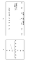
- 2A shows the coordinate system 1 and coordinate system 2, and the arrangement of points P[0] . . . P[10], and FIG. ] .
- FIG. 3 shows the results for 0 degrees.
- the view of FIG. 3 is the same as that of FIG. It can be seen from FIG. 3 that the normalized coordinates xp[1] . . . xp[9] and the coordinates x2p[1] .
- the captured images 1 and 2 are geometrically corrected so that the positions of the reference points match with the points P[0] and P[10] as reference points, the positions of the non-reference points do not match. I understand.
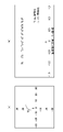
- FIG. 4 shows the results at 20 degrees.
- the view of FIG. 4 is the same as that of FIG. 4, similar to FIG. 3, the normalized coordinates xp[1] . . . xp[9] do not match the coordinates x2p[1] . 0] and P[10] as the positions of the reference points, even if the captured images 1 and 2 are geometrically corrected so that the positions of the reference points match, the positions of the non-reference points do not match.
- the optical axes of the imaging systems 1 and 2 are parallel and there is no positional deviation in the direction of the optical axis (the imaging system 1 and the imaging system 2 are aligned), even if the captured images 1 and 2 are geometrically corrected so that the positions of the reference points on the surface of the object match, the positions of the non-reference points do not match.
- FIG. 5 schematically shows the imaging system 1, the imaging system 2, and the surface of the object to be imaged in the xy coordinate space. Since only the surface of the object differs from FIG. 1, only the surface of the object will be described.
- the object surface is a circular arc with center (xc, yc) (coordinates in coordinate system 1) and radius r.
- FIG. 7 shows the results for 0 degrees.
- the view of FIG. 7 is the same as that of FIG. It can be seen from FIG. 7 that the normalized coordinates xp[1] . . . xp[9] and the coordinates x2p[1] .
- the captured images 1 and 2 are geometrically corrected so that the positions of the reference points match with the points P[0] and P[10] as reference points, the positions of the non-reference points do not match. I understand.
- FIG. 8 shows the results obtained at 20 degrees.
- the view of FIG. 8 is the same as that of FIG. 8, the normalized coordinates xp[1] . . . xp[9] and the coordinates x2p[1] . . . x2p[9] do not match; 10] as a reference point, even if the captured image 1 and the captured image 2 are geometrically corrected so that the positions match, the positions of the non-reference points do not match.
- the space of the imaging target is two-dimensional for the sake of explanation, but the actual space of the imaging target is three-dimensional.
- the surface of the object is assumed to be a plane or a curved surface, and reference points and non-reference points are considered on the surface. Even if the coordinates of the points are obtained and normalized so that the coordinates of the reference points match, the coordinates of the normalized non-reference points of the imaging system 1 and the imaging system 2 do not match. It can be seen that even if the captured image 1 and the captured image 2 are geometrically corrected, the positions of the non-reference points do not match.
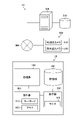
- FIG. 9 is a diagram showing the overall configuration of the image processing system according to the embodiment.
- an image processing device 20 image processing device
- a server 500 server 500
- a database 510 database
- a camera 600 imaging device
- NW network
- the image processing system 10 can be configured using devices (information terminals) such as personal computers, tablet terminals, and smartphones.
- the image processing apparatus 20 includes a processing unit 100 (processor), a recording unit 200, a display unit 300, and an operation unit 400. These units are connected to each other to transmit and receive necessary information. Each of these parts may be housed in one housing, or may be housed in an independent housing. Also, each element may be arranged at a remote location and connected via a network.
- the image processing device 20 acquires an image of the bridge 710 (an example of a concrete structure) shown in FIG. 10, for example, and performs processing such as detection of damage and deformation, alignment of images, and the like.
- the bridge 710 has wall balustrades 712 , floorboards 720 (only some of which are shown), girders 722 , and piers 730 .
- "alignment between the first image and the second image” means that the value of the first image corresponding to the same point on the surface of the object corresponds to the value of the second image. means to attach
- FIG. 11 is a diagram showing the functional configuration of the processing unit 100.
- the processing unit 100 includes an image acquisition unit 102, a reference point identification unit 103, a position information acquisition unit 104, a non-reference point position estimation unit 106, an image value estimation unit 108, a superimposed data generation unit 110, and damage detection.
- processors include, for example, a CPU (Central Processing Unit) that is a general-purpose processor that executes software (programs) to realize various functions, a GPU (Graphics Processing Unit) that is a processor specialized for image processing, Also included are Programmable Logic Devices (PLDs), which are processors whose circuit configurations can be changed after manufacturing, such as FPGAs (Field Programmable Gate Arrays).
- PLDs Programmable Logic Devices
- FPGAs Field Programmable Gate Arrays
- Each function may be implemented by one processor, or may be implemented by multiple processors of the same type or different types (for example, multiple FPGAs, a combination of CPU and FPGA, or a combination of CPU and GPU).
- a plurality of functions may be realized by one processor. More specifically, the hardware structure of these various processors is an electrical circuit that combines circuit elements such as semiconductor elements.
- a computer-readable code of the software to be executed (for example, various processors and electric circuits constituting the processing unit 100, and / or combinations thereof) is recorded in a non-temporary recording medium (memory) such as ROM or flash memory, and the computer refers to the software.
- the software recorded on the non-temporary recording medium includes an image processing program for executing the image processing method according to the embodiment of the present invention, and data used when executing the image processing program (information indicating the position of the reference point data, data used for estimating the positions of non-reference points, surface shape data of objects, etc.).
- Codes may be recorded in non-temporary recording media (including the recording unit 200) such as various magneto-optical recording devices and semiconductor memories instead of the ROM. During execution, information recorded in a recording device such as the recording unit 200 is used as necessary. Also, during execution, RAM (Random Access Memory), for example, is used as a temporary storage area.
- RAM Random Access Memory
- a part or all of the functions of the processing unit 100 may be realized by a server (processor) on the network, and the image processing apparatus 20 may perform data input, communication control, display of results, and the like.
- a server processor
- an Application Service Provider type system is constructed including servers on the network.
- a recording unit 200 (recording device, memory, non-temporary recording medium) is a non-temporary recording medium such as a CD (Compact Disk), a DVD (Digital Versatile Disk), a hard disk (Hard Disk), various semiconductor memories, etc., and its control unit. It consists of a visible image, an infrared image, superimposed data and superimposed image of the visible image and the infrared image, information indicating the positions of reference points and non-reference points, shape data of the surface of the object (three-dimensional surface), damage information, etc. Recorded. An image processing program for executing the image processing method according to the embodiment of the present invention and data used for executing the image processing program may be recorded in the recording unit 200 .
- the operation unit 400 includes a keyboard 410 and a mouse 420, and the user can perform operations required for image processing according to the embodiment of the present invention using these devices.
- the monitor 310 may be used as an operation unit.
- the display unit 300 includes a monitor 310 (display device).
- a monitor 310 is, for example, a device such as a liquid crystal display, and can display acquired images and processing results.
- Information such as visible images and infrared images is recorded in the database 510 , and the server 500 controls communication with the image processing apparatus 20 .
- the image processing device 20 can acquire information recorded in the database 510 .
- the camera 600 (imaging device, imaging system) includes a visible light camera 610 that captures an image of an object (subject) with light in a wavelength band that includes at least part of the visible light wavelength band, and a visible light camera 610 that captures at least part of the infrared wavelength band. and an infrared camera 620 that captures an image of the object with light in the wavelength band including.
- a visible image and an infrared image (a plurality of two-dimensional images captured in different wavelength bands) can be obtained by imaging the same object from different positions.
- Camera 600 may be mounted on a pan and/or tiltable head. Also, the camera 600 may be mounted on a movable vehicle, robot, or flying object (such as a drone).
- the relationship between the coordinate systems of the visible light camera 610 and the infrared camera 620 (parameter values indicating the relationship between the position of the origin and the direction of the coordinate system) is known and stored in a memory such as the recording unit 200. and
- the positions and directions of the visible light camera 610 and the infrared camera 620 may be fixed at predetermined positions and directions, and an image may be captured, and parameters calculated from the obtained visible image and infrared image may be stored in the memory.
- many infrared cameras also have a built-in visible light camera, and when an infrared image is captured by the infrared camera, a visible image can also be captured by the visible light camera at the same time.
- the imaging positions and directions of the visible light camera 610 and the infrared camera 620 may be specified by separate measurement means. GPS or Wi-Fi positioning can be applied to specify the imaging position, and known methods such as a gyro sensor and an acceleration sensor can be applied to specify the imaging direction.
- the processing unit 100 (processor) can use the stored information as needed.
- FIG. 12 is a flowchart showing the image processing procedure (each step of the image processing method) according to the embodiment.
- the image acquisition unit 102 acquires a visible image and an infrared image of the same object taken from different positions (step S100: image acquisition processing, image acquisition step).
- the image acquisition unit 102 can acquire images from the camera 600 , the database 510 and the recording unit 200 . Further, the image acquiring unit 102 can acquire a visible image and an infrared image of an object such as a concrete structure.
- the relationship between the coordinate systems of the visible image and the infrared image (the relationship between the imaging position and the imaging direction) is known.
- the visible image may be referred to as the first image
- the infrared image may be referred to as the second image.
- You may treat as a 1st image or a 2nd image.
- a damage detection unit 111 detects damage (deformation, defect) from the visible image and the infrared image.
- the items to be detected are, for example, the position, quantity, size, shape, type, and degree of damage. Further, the types of damage include, for example, cracks, delamination, water leakage, floating, cavities, corrosion, exposure of reinforcing bars, and the like.
- the damage detection unit 111 can detect damage using a known method (for example, a method based on local feature amounts of an image). Moreover, the damage detection unit 111 may detect damage using a trained model (for example, various neural networks) configured by machine learning such as deep learning.
- the reference point identification unit 103 and the position information acquisition unit 104 acquire information indicating the position of the reference point from the acquired image (step S110: reference point position information acquisition process, reference point position information acquisition process).
- This processing includes identification of reference points in the visible image and infrared image (identification processing, identification step) and acquisition of information indicating the position of the reference point on the surface of the object (acquisition processing, acquisition step).
- FIG. 13 is a schematic diagram showing how the position of the reference point RP on the surface SS of the object is determined
- FIG. 14 is an enlarged view of the visible image I1 and the infrared image I2 in FIG.
- FIG.13 and FIG.14 in order to simplify description, only one surface of an object is illustrated.
- the object other than the surface is displayed in black.
- the reference points specified in the visible image I1 and the infrared image I2 are indicated by white circles. A detailed description will be given below.
- the reference point identification unit 103 first identifies reference points in the visible image and the infrared image.
- the reference point specifying unit 103 may determine a marker (for example, a metal foil such as aluminum foil) that can be specified by both the visible image and the infrared image on the surface of the object in advance, and then, in the captured visible image and the infrared image, Marker positions can be identified.
- a marker for example, a metal foil such as aluminum foil
- the reference point identifying unit 103 may identify and extract the reference point based on the spatial distribution of the signal values of the visible image and the infrared image.
- a known image correlation method for obtaining corresponding points between two images using a stereo camera or the like may be used. That is, in the visible image and the infrared image, regions of a predetermined size are extracted while changing the coordinates, the correlation is evaluated, and the coordinates of the region with the highest correlation (similarity) are obtained as corresponding points.
- the reference point identifying unit 103 identifies and extracts only corresponding points having a correlation (similarity) between the visible image and the infrared image greater than or equal to a predetermined value as reference points.
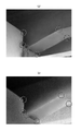
- FIG. 15 shows an example of identifying reference points in a visible image (part (a) in FIG. 15) and an infrared image (part (b) in FIG. 15) of a concrete structure (for example, the bridge 710 shown in FIG. 10). It is a figure which shows. In the example shown in FIG.
- the reference point identifying unit 103 can identify, for example, the circled locations as reference points based on the correlation (similarity). Note that the reference point identification unit 103 preferably evaluates the absolute value of the correlation value as the correlation (similarity) because the signal value relationship may be reversed between the visible image and the infrared image.
- the reference point specifying unit 103 can obtain the value of the visible image and the value of the infrared image corresponding to the reference point when specifying the reference point in the visible image and the infrared image. That is, the visible image value and the infrared image value corresponding to the reference point can be obtained in step S110.
- the values of the visible image corresponding to the reference point are, for example, RGB (Red Green Blue) values corresponding to the reference point.
- the value of the infrared image corresponding to the reference point is, for example, an IR (infrared) value corresponding to the reference point.
- the position information acquisition unit 104 obtains the position on the surface of the object (the position in the three-dimensional space of the imaging target) for each reference point based on the positions in the visible image and the infrared image. Based on the position of the reference point on the image, the direction of the reference point in the coordinate system of the imaging system of the image can be identified.
- the captured image is an image obtained by projecting each point on the surface of the object onto the imaging surface in the direction of the optical center. Therefore, the position of the reference point on the image is the position obtained by projecting the reference point on the surface of the object onto the imaging surface in the direction of the optical center.
- the reference point on the object surface is in the direction of the straight line connecting the optical center and the reference point on the imaging plane. Since the relationship between the positions and directions of (the coordinate system of) the imaging system of the visible image and (the coordinate system of) the imaging system of the infrared image is known, the position information acquiring unit 104 can specify from the position of the reference point in the visible image.
- the direction for example, in the schematic diagram of FIG. 13, the direction of the straight line (solid line) connecting the optical center O1 of the imaging system of the visible image I1 and the reference point on the imaging surface IS1) and the position of the reference point in the infrared image.
- FIG. 13 the direction of a straight line (dotted line) connecting the optical center O2 of the imaging system of the infrared image I2 and the reference point on the imaging plane IS2). Intersecting points in the dimensional space; for example, in the schematic diagram of FIG. , it can be obtained as the position of the reference point RP on the object surface SS.
- FIG. 1 the schematic diagram of FIGS. 1, 5, 13 and 14.
- the boundaries of the surface of the object can also be extracted as reference points.
- the visible image and the infrared image shown in FIG. 15 not only edges and curved portions (curved portions) of the surface of the object but also other boundary portions are extracted as reference points.
- locations extracted as locations with high correlation (similarity) on the boundary of the surface of the object are indicated by dotted line circles (elliptical symbols). It is shown in FIG. In FIG.
- the boundary is a straight line
- the image correlation method is used to extract a region of a determined size at the boundary of the visible image (or infrared image) and correlate it with the region of a determined size of the infrared image (or visible image). Evaluating (similarity) yields high correlation (similarity) in multiple regions along the boundary. If the surface boundary of the object is a curve, the correlation (similarity) is high at each point along the curve. In any case, not only the edges of the surface of the object, but also other boundaries (straight lines or curves) can be extracted as high correlation (similarity) points.
- At least one reference point is preferably a point that exists at the edge of the object, a curved portion (curved portion), or the boundary.
- the position information acquisition unit 104 performs the following operations on at least one of the visible image and the infrared image (at least one of the first image and the second image) for the edge, curved portion, and boundary of the object.
- An enhancement process for enhancing one or more of them may be performed, and the reference point position information acquisition process (reference point position information acquisition process) may be executed using the image subjected to the enhancement process.
- a point on the visible image and a point on the infrared image that can be identified as the same point on the surface of the object are called "reference points”.
- the edge of the object surface described above one point of the edge can be specified as the same point in the visible image and the infrared image.
- the boundary of the surface of the object described above can also be specified as the same point in the visible image and the infrared image at each point on the boundary. Therefore, in the embodiment of the present invention, a point that can be identified as "the same point on the surface of the object” is called a “reference point” whether it is an edge or a boundary of the surface of the object.
- both a single point (point) and a plurality of points (lines) on the surface of the object are called “reference points”.
- reference points both a single point (point) and a plurality of points (lines) on the surface of the object.
- reference points depending on whether there is one reference point (point) or multiple points on a line (lines), there are several methods for determining the position of the reference point on the surface of the object based on the positions of the reference points in the visible image and the infrared image. Since they are different, it is necessary to distinguish between them (the case where there is one reference point and the case where there are multiple points on the line).
- the position information acquisition unit 104 obtains a straight line connecting the origin (optical center) of the coordinate system of the imaging system of the visible image and the reference point on the imaging surface, A point of intersection of a straight line connecting the origin (optical center) of the coordinate system of the imaging system of the infrared image and the reference point on the imaging surface can be obtained as the position of the reference point on the surface of the object.
- the position information acquisition unit 104 determines the origin (optical center) of the coordinate system of the visible image (or infrared image) imaging system and one reference point on the line on the imaging plane.
- a plane that includes a straight line connecting points, the origin (optical center) of the coordinate system of the infrared image (or visible image) imaging system, and a line on the imaging plane A plane consisting of straight lines connecting points) can be obtained as the position of the one reference point on the object surface. If the reference points are at multiple points on a line (line), this method can determine the position on the object surface for each reference point on the line.
- the position information acquisition unit 104 uses the latter method described above, that is, a straight line corresponding to one point on the straight line in one image and a plane corresponding to the straight line in the other image. It is necessary to determine the position of each reference point on the straight line on the object surface by the method of determining the intersection point with .
- the position information acquiring unit 104 uses the former method, that is, the position on the curve of one image, as long as each point on the curve in the visible image and the infrared image can be specified.
- Objects of each reference point on the curve by a method of obtaining intersection points of a straight line corresponding to one point and a straight line corresponding to a point specified as the same point as that one point on the curve of the other image It is also possible to find the position on the object surface.
- a plane containing the origin (optical center) of the coordinate system of the imaging system of one image and a line on the imaging plane and the origin (optical center) of the coordinate system of the imaging system of the other image It is also possible to obtain the position of the reference point of the line of each image on the object surface by intersecting the line of the plane containing the line on the imaging plane.
- the non-reference point position estimating unit 106 calculates a reference point on the object surface (three-dimensional surface) based on the position of the reference point on the object surface (three-dimensional surface) (from the information indicating the position of the reference point).
- the positions of the non-reference points that are points other than the reference point are estimated (step S120: non-reference point position estimation process, non-reference point position estimation step).
- This processing includes processing (shape estimation processing, shape estimation step) for estimating the shape of the surface of the object (three-dimensional surface) based on the position of the reference point on the surface of the object (three-dimensional surface); and a process (position estimation process, position estimation process) of estimating the positions of non-reference points based on the shape of the surface (three-dimensional surface).
- processing shape estimation processing, shape estimation step
- position estimation process position estimation process
- the non-reference point position estimator 106 excludes such triangular planes, and for all triangular planes formed by the three reference points so that there are no other reference points inside them, Form the plane of each triangle.
- the non-reference point position estimator 106 determines whether the reference point is a point or a line to generate a triangular plane. It is preferable to change the rules that form the . Specifically, the non-reference point position estimating unit 106 forms a triangular plane so that the reference point is the vertex for the reference point of a point, and It is preferable to form a triangular plane so that the reference point (line) is on one side.
- the line is a curve
- the plane on which the curve forms one side is neither a triangle nor necessarily a plane. , may be concatenated to estimate the shape of the object surface.
- the surface of the object is not necessarily connected in the entire range of the visible image and the infrared image, and there are cases where the surface is discontinuous due to shadows.
- the visible and infrared images shown in FIG. 15 (and FIG. 16) also include discontinuities on the surface of the object.
- a triangular plane formed based on reference points in such a discontinuous portion is incorrect as an approximation of the shape of the object surface. Therefore, in order to accurately estimate the surface shape even in such a case, the non-reference point position estimating unit 106 discriminates each connected area of the surface of the object in the visible image and the infrared image, and determines each connected area.
- the non-reference point position estimator 106 can determine connected regions based on the signal values of the visible image and the infrared image, and spatial features such as edges and textures.
- the visible image is usually composed of RGB images (images in red, green, and blue wavelength bands) obtained by respectively imaging reflection intensity distributions in three different wavelength bands in the visible light wavelength band.
- the non-reference point position estimation unit 106 can determine connected regions based on the signal values of the RGB images and spatial features such as edges and textures of each image. For example, as shown in FIG. 15 (and FIG. 16), the non-reference point position estimating unit 106 first extracts a pixel group that can be regarded as a concrete surface from each pixel of the visible image when the object is a concrete structure.
- each pixel is extracted as a pixel group that can be regarded as the concrete surface.
- the non-reference point position estimating unit 106 further distinguishes the pixel group more finely based on the RGB signal values of each pixel and the spatial feature.
- the non-reference point position estimator 106 fills and dilates each pixel group by a morphological dilation operation.
- the non-reference point position estimating unit 106 shrinks each expanded pixel group to an optimal area using the active contour method, and converts the area corresponding to each pixel group into a connected area. can be determined as
- the non-reference point position estimation unit 106 can apply Snakes, Level set method, etc. as the active contour method.
- the non-reference point position estimating unit 106 determines connected regions based on both the visible image and the infrared image. There are many methods such as the Mean Shift method and the Graph Cuts method for determining connected regions (distinguishing and determining each region sandwiching a discontinuous boundary). Non-reference point position estimation section 106 may apply any of these methods to determine connected regions. The non-reference point position estimating unit 106 may determine the method of determining the connected regions according to the user's operation.
- the non-reference point position estimation unit 106 may apply a machine learning technique to determine connected regions.
- CNN Convolutional Neural Network
- FCN fully convolution network
- U-net Convolutional Networks for Biomedical Image Segmentation
- Seg Net A Deep Convolutional Encoder-Decoder Architecture for Image Segmentation
- the method of determining connected regions is not particularly limited as long as it is based on the features of the visible image and the infrared image, and the non-reference point position estimation unit 106 may apply any of these methods.
- the types of visible images (types of signal values) used for determination are not limited to three types (RGB), but may be one type, two types, or four or more types.
- Each connected area on the surface of the object is defined by a directional area in (the coordinate system of) the imaging system of the visible image and the infrared image. Specifically, for each of the visible image and the infrared image, the area in the direction of the straight line connecting the origin (optical center) of the coordinate system of the corresponding imaging system and each pixel of the connected area on the imaging surface (that is, A region in a direction surrounded by straight lines connecting the origin of the coordinate system of the corresponding imaging system and each pixel on the boundary of the connected regions on the imaging plane).
- the overlapping region is regarded as the region where the surface of the object is connected (either the visible image or the infrared image However, if a discontinuous boundary is allowed, to limit the area connected by the boundary).
- the shape of the object surface in that region may be estimated.
- the surface shape may be estimated by fitting a free-form curved surface such as a Bezier curved surface or a B-spline curved surface to the reference points on the boundaries and inside of the connected regions (in this case, the fitted curved surface is not necessarily all does not need to pass through the reference point).
- each connected region on the surface of the object may be further divided into each region that is smoothly connected (where the surface of the object has a point where the inclination changes abruptly If there is, the area may be divided by using the location where the inclination changes abruptly as a boundary).
- the method of discrimination based on the signal values of the visible image and the infrared image, and spatial features such as edges and textures, it is possible to discriminate each connected area on the surface of the object, and further finely, Each region that is smoothly connected can also be discriminated (each region separated by a point where the inclination changes abruptly can also be discriminated).
- the surface shape may be known in advance (it is known that the surface has a predetermined shape).
- the surface is often flat as in the example of FIG. 15 (and FIG. 16).
- the surface is often cylindrical.
- the non-reference point position estimating unit 106 predetermines a function representing the shape of the surface such as a plane, cylindrical surface, or spherical surface instead of a free-form surface.
- the non-reference point position estimating unit 106 calculates the reference points at the boundary and inside of the region.
- the surface shape may be estimated by fitting a plane that best fits the positions of the points. For example, in the case of the schematic diagram of FIG.
- the non-reference point position estimation unit 106 performs The shape of the object surface SS is estimated by fitting a plane that best fits the positions of the four reference points RP on the boundary of the region. Further, for example, when it is known in advance that the surface of the object is a cylindrical surface, the non-reference point position estimating unit 106 may estimate the surface shape of the object by fitting the cylindrical surface.
- each smoothly connected area on the surface of the object was discriminated based on the signal value of the visible image and spatial features such as edges and textures.
- An example of the results is shown in FIG. In FIG. 17, the surface of the area shown in part (a) is discontinuous (not connected) to the surface of other areas, and the areas shown in parts (b), (c), and (d) are discontinuous.
- the surface of is continuous (connected) but not smooth (separated by abrupt slope changes).
- the non-reference point position estimator 106 performs The surface shape can be estimated by fitting a plane that best fits the positions of the reference points of the points and the reference points of the lines on the object surface.
- the non-reference point position estimation unit 106 estimates the surface shape if at least three reference points (reference points not on the same straight line) are on the surface. can be estimated. Also, when the shape of the object surface is spherical, the surface shape can be estimated if there are at least four reference points (reference points not on the same plane) on the surface. Also, when the shape of the object surface is a cylindrical surface, the surface shape can be estimated if at least five reference points are on the surface.
- the minimum required for estimating the surface shape by optimizing and fitting the parameters of the function according to the number of parameters (independent parameters) of the function number of reference points is determined.
- the accuracy of surface shape estimation improves as the number of reference points increases.
- the non-reference point position estimating unit 106 uses fewer reference points
- the surface shape of the object can be estimated based on For example, if the object surface is a plane, for example, if one of the two angles between the coordinate system of either the visible image or the infrared image and the object surface (plane) is determined (visible image and infrared In any coordinate system of the image, one angle (either ⁇ or ⁇ ) is determined when the direction of the normal vector of the surface (plane) of the object is represented by two angles ⁇ and ⁇ in polar coordinates. ), the surface shape can be estimated if at least two reference points lie on the surface.
- the surface shape can be estimated.
- the surface of the object is a cylindrical surface
- one of the two angles formed by the coordinate system of either the visible image or the infrared image and the direction of the axis of the cylindrical surface of the object is determined.
- the direction of the axis of the cylindrical surface of the object is represented by two angles ⁇ and ⁇ in polar coordinates in either the coordinate system of the visible image or the infrared image, one angle (either ⁇ or ⁇ ) is determined
- the surface shape can be estimated if at least four reference points lie on the surface.
- the surface shape can be estimated if at least three reference points are on the surface. can.
- the surface shape can be estimated if at least one reference point is on the surface.
- the shape of the surface of the object may be grasped from design drawings or CAD data (CAD: Computer-Aided Design).
- CAD Computer-Aided Design
- a three-dimensional model created from an image of an object may also be used.
- the non-reference point position estimating unit 106 can arrange non-reference points by various methods for the shape of the object surface (three-dimensional surface) estimated by the above method. For example, a non-reference point may be arranged corresponding to each pixel of the visible image (or infrared image).
- arranging a non-reference point corresponding to each pixel of the visible image (or infrared image) means that the origin (optical center) of the coordinate system of the imaging system of the visible image (or infrared image) and the visible Placing a non-reference point in the direction of a straight line connecting the coordinates of each pixel on the imaging surface corresponding to the image (or infrared image), that is, placing the non-reference point based on the perspective projection model (central projection model).
- "arranging” means defining a straight line corresponding to each non-reference point (that is, the position of the non-reference point on the surface of the object is not yet estimated).
- the non-reference point position estimating unit 106 expands the imaging surface, and then calculates the non-reference point in the direction of a straight line parallel to the optical axis (z-axis of the coordinate system) from the coordinates of each pixel on the imaging surface. It is also possible to place the non-reference points based on the parallel projection model (orthographic projection model). An image based on the parallel projection model is called an orthoimage (orthophoto). That is, the non-reference point position estimation unit 106 may arrange non-reference points corresponding to each pixel of the orthorectified image.
- the parallel projection model can represent the shape of the object more accurately without distortion (non-reference points can be arranged at equal intervals with respect to the object).
- the non-reference point position estimating unit 106 uses a perspective projection model or a Non-reference points may be placed based on the parallel projection model.
- the non-reference points may be arranged based on the perspective projection model or the parallel projection model in the imaging system (coordinate system) at any position and direction.
- FIG. 18 is a schematic diagram showing how non-reference points are arranged based on the parallel projection model (orthographic projection model) in the schematic diagram shown in FIG.
- the imaging surface of the non-reference point is defined as S0, and from the coordinates of each pixel on the imaging surface S0, a straight line (a straight line indicated by a dotted line) parallel to the optical axis (the z-axis of the coordinate system of the non-reference point) A non-reference point is placed in the direction.
- the straight lines corresponding to the respective non-reference points are sparsely shown for easy understanding of the explanation.
- FIG. 18 also shows the object surface SS estimated based on the information indicating the position of the reference point RP.
- the imaging system (coordinate system) based on the non-reference points will be referred to as the imaging system (coordinate system) of the non-reference points.
- the non-reference point position estimating unit 106 calculates straight lines in the corresponding directions for each non-reference point arranged based on the non-reference point imaging system (coordinate system). and the estimated position of the intersection with the surface of the object is determined as the position of the non-reference point on the surface of the object.
- a shape connecting triangular planes for each non-reference point, a triangle through which a straight line in the corresponding direction passes is determined, and the intersection of the plane of the triangle and the straight line is determined. I'd like to find the location.
- the non-reference point position estimating unit 106 does not have to obtain the positions of the non-reference points in that direction, and only needs to obtain the positions of the non-reference points within the area where the surface of the object is connected.
- the corresponding straight line (straight line indicated by a dotted line) and the target estimated based on the position of the reference point RP
- the position of the intersection with the object surface SS is obtained as the position NRP of the non-reference point on the object surface SS.
- the non-reference point position estimating unit 106 previously estimated the positions of the reference points on the surface of the object and the shape of the surface of the object. Each surface must be transformed into a non-reference point coordinate system. In the following description, conversion between the visible image coordinate system and the non-reference point coordinate system, and conversion between the infrared image coordinate system and the non-reference point coordinate system are necessary here and there.
- the image value estimation unit 108 (processor) generates a visible image (first image) and the value of the infrared image (second image) are estimated and associated (step S130: association processing, association step). Since there are two methods for estimating the values of an image, they will be described in turn. Note that the value of the visible image (first image) and the value of the infrared image (second image) corresponding to the reference point are obtained in step S110 by obtaining the values of the visible image (first image) and the infrared image ( 2nd image) when identifying the reference point.
- the first method estimates the value of the corresponding visible image by projecting each non-reference point onto the imaging plane of the visible image, and estimates the value of the corresponding infrared image by projecting it onto the imaging plane of the infrared image. It is a way to The image value estimation unit 108 converts the coordinates of the non-reference points on the surface of the object in the imaging system (coordinate system) of the non-reference points into the coordinates in the imaging system (coordinate system) of the visible image, and then converts the coordinates of the visible image.
- the image value estimator 108 can estimate the values of the corresponding visible image and infrared image for each non-reference point by the above method.
- a second method is to project each pixel of the visible image and each pixel of the infrared image onto the surface of the object and estimate the values of the visible and infrared images corresponding to each non-reference point.
- the captured image is an image obtained by projecting each point on the surface of the object onto the imaging surface in the direction of the optical center. Therefore, the image value estimating unit 108 determines the position of the intersection of the estimated object surface and a straight line passing through the coordinates of each pixel on the imaging surface of the visible image from the optical center of the imaging system of the visible image (the origin of the coordinate system).
- the image value estimator 108 can also estimate infrared image values (second image values) at positions of non-reference points on the object surface.
- the image value estimator 108 naturally calculates the value of the visible image (or infrared image) corresponding to each non-reference point. , the value of each pixel of the visible image (or infrared image) may be adopted as it is.
- FIG. 19 is a diagram showing the results of estimating the values of the visible image and the infrared image at each pixel on the non-reference point imaging surface S0 shown in the schematic diagram of FIG. Specifically, for each non-reference point corresponding to each pixel on the imaging surface S0, based on the position NRP on the surface of the object and the visible image I1 and infrared image I2 shown in FIG. 14 (and FIG. 13), FIG. 4 shows the result of estimating corresponding visible and infrared image values according to the method described above; Part (a) of FIG. 19 shows the results of estimating the values of the visible image, and part (b) of the same figure shows the results of estimating the values of the infrared image. Peripheral black areas indicate areas other than the object surface). Note that FIG. 19 also shows the values of the visible image and the infrared image at the pixels corresponding to the reference point RP among the pixels on the imaging surface S0 shown in FIG.
- the superimposed data generation unit 110 and the display control unit 112 (display control unit) generate visible image values (first image values) and infrared image values (second image values) corresponding to each point including the non-reference points. ) are superimposed on the same pixel position, and/or the visible image value (first image value) and the infrared image value (second image value) corresponding to each point including non-reference points ) are superimposed on the same pixel position on the monitor 310 (display device) (step S140: data generation processing/data generation step, display processing/display step).
- Each point including a non-reference point means that each point includes at least a non-reference point, and may also include reference points and other points. There are various known methods for superimposing two types of images, and the superimposed data generation unit 110 may use any of these methods.
- FIG. 20 is a diagram showing an example of the result (superimposed image) of superimposing the values of the visible image and the values of the infrared image on the same image position in the example shown in FIG.
- the display control unit 112 can display this image on the monitor 310 . Note that the weight value is not limited to this, and can be set as appropriate.
- FIG. 21 is a diagram showing an example of superimposed data in tabular form.
- the superimposed data generation unit 110 generates the position on the target object, the value at the corresponding point on the visible image, and the , and the values at the corresponding points in the visible image and the infrared image can be grasped for the points (reference points or non-reference points) on the object.
- FIG. 22 is a diagram showing examples of a visible image, an infrared image, and a superimposed image. Parts (a) to (c) of FIG. 22 show a visible image, an infrared image, and a superimposed image of the same part of the object, respectively.
- the visible image clearly shows the surface damage (crack CR) of the object
- the infrared image clearly shows the internal damage (cavity CAV) of the object.
- superimposed images that are precisely aligned as described above allow observation of surface and internal damage behavior at the same point of the object. Then, as described above, among the damages inside the object, it is possible to discriminate between those accompanied by surface damage such as cracks and peeling and those not accompanied.
- positional deviation can be reduced.
- the points of the first image and the points of the second image do not necessarily have to be associated.
- the float in particular in diagnosing an internal defect such as a float based on an infrared image, by reducing the misalignment between the visible image and the infrared image when also using the visible image at the same time, the float can be detected. can improve the diagnostic performance of internal defects.
- the recording control unit 114 (processor) can cause the recording unit 200 to record superimposed data and/or superimposed images illustrated in FIGS.
- step S100 image acquisition processing, image acquisition step
- the image acquisition unit 102 may acquire multiple images taken at different positions and/or orientations for each.
- the position information acquisition unit 104 identifies and extracts the same reference point in a plurality of visible images and infrared images in step S110 (reference point position information acquisition process, reference point position information acquisition step). (It is possible to predefine a marker on the surface of the object, or to specify the reference point based on the spatial distribution of the signal values of the image).
- the position information acquisition unit 104 when specifying a reference point based on the spatial distribution of signal values of an image, and using an image correlation method as a method thereof, the position information acquisition unit 104, for example, among a plurality of visible images and infrared images, the imaging position and/or after specifying and extracting the reference points by the image correlation method between the two images having close directions, based on the position (coordinate) relationship of the specified and extracted reference points in each image, a plurality of visible The same fiducials can be identified and extracted in the image and infrared image.
- the position information acquisition unit 104 determines the position of each reference point on the surface of the object based on the positions in the plurality of visible images and infrared images (compared to the case where there is one visible image and one infrared image). It can be obtained with higher precision.
- the position information acquisition unit 104 obtains each straight line (reference point is the reference point of a point), or each plane (if the reference point is a reference point of a line), the point (or line) where the Good luck.
- step S100 when a plurality of images are acquired for each of the visible image and the infrared image, one image is selected for each of the visible image and the infrared image after step S120, and the image value estimating unit 108 selects one image for each.
- the values of the visible image and the infrared image corresponding to each non-reference point are estimated by the above method, and superimposed data is generated and/or displayed by the superimposed data generation unit 110 and the display control unit 112 .
- the non-reference point position estimating unit 106 uses the signal value And each region is discriminated based on spatial features such as edges and textures, and among the regions in each direction discriminated in each of a plurality of visible images and infrared images, the overlapping region (inner region) is the object It may be regarded as a connected area of the surface or a smoothly connected area. Further, when estimating the values of the visible image and the infrared image corresponding to each non-reference point in step S130, the image value estimating unit 108 calculates the corresponding value from each of the plurality of visible images for each non-reference point.
- the image value estimator 108 may obtain corresponding values from each of a plurality of infrared images, and obtain an average value of those values as the value of the infrared image corresponding to the non-reference point.
- the image acquisition unit 102 can obtain the imaging position and direction of each image by applying SfM (Structure from Motion; multi-viewpoint stereo photogrammetry) technology. Also, by using Visual SLAM (Simultaneous Localization and Mapping) technology, it is possible to similarly obtain the imaging position and direction of each image.
- SfM Structure from Motion; multi-viewpoint stereo photogrammetry
- Visual SLAM Simultaneous Localization and Mapping
- step S110 the position information acquisition unit 104 separately specifies the distance Each reference point may be directly set on the surface of the object and the position thereof may be obtained by a measurement method (distance measuring means, distance measuring device).
- a measurement method distance measuring means, distance measuring device
- the distance measurement method is a sensor such as LiDAR (Light Detection And Ranging), a stereo camera, a TOF (Time Of Flight) camera, an ultrasonic sensor, or the like.
- the position information acquiring unit 104 sets respective reference points on the surface of the object, and sets the values of the visible image (first image) and the infrared image (second image) corresponding to the respective reference points. values can be obtained. Specifically, the relationship between the positions and directions of (the coordinate system of) the distance measurement system, (the coordinate system of) the imaging system of the visible image, and (the coordinate system of) the imaging system of the infrared image is known.
- the position information acquisition unit 104 sets each reference point on the surface of the object by the distance measurement method (and obtains the position thereof), the positions of those reference points in the visible image (first image) (visible The position of the image (first image) projected onto the imaging plane) and the position of the infrared image (second image) (the position of the infrared image (second image) projected onto the imaging plane) can be obtained. Therefore, the position information acquisition unit 104 can obtain the values of the visible image (first image) and the infrared image (second image) corresponding to those reference points.
- step S130 association processing, correspondence attachment step
- the image value estimating unit 108 estimates the value of the visible image (first image) and the value of the infrared image (second image) corresponding to the non-reference points
- Corresponding visible image values (first image) and infrared image values (second image) may be determined.
- the visible image may be an image captured by the stereo camera.
- the problem to be solved by the embodiments of the present invention is not limited to visible images and infrared images, and occurs regardless of the type of image.
- the problem of ⁇ the positions of non-reference points other than the reference point are shifted'' is It occurs regardless of the type of image.
- the above problems occur in any image such as a near-infrared image, an ultraviolet image, and a fluorescence image. Therefore, the embodiments of the present invention are effective regardless of the type of image.
- two images of different types refer to images captured by cameras having sensitivities in different wavelength ranges.
- Having sensitivity in different wavelength ranges means not only having sensitivity in each wavelength range that does not overlap at all, but also having sensitivity in each wavelength range that is partially overlapping and partially different. Including the case of having.
- the spectral characteristics of each sensitivity are different, and the wavelength at which the sensitivity is maximized (peak sensitivity wavelength) is different. (including cases where it can be considered to have sensitivity in the wavelength range).
- image indicates a two-dimensional image captured by a camera.
- the position of the non-reference point is shifted means that the two images corresponding to the same point (non-reference point) on the surface of the object are shifted. It means that the position in the two respective images corresponding to another point (non-reference point) on the object surface is erroneously the same. That is, two respective image values corresponding to different points (non-reference points) on the object surface are erroneously regarded as two respective image values corresponding to the same point (non-reference points).
- the image processing apparatus is an image processing apparatus that includes a processor, and the processor uses first and second images obtained by imaging the same object from different positions. acquire a first image and a second image, which are two-dimensional images captured in different wavelength bands, and align the first image and the second image at a reference point on the three-dimensional surface of the object; Acquire information indicating the position of the reference point, which is the reference point of the 3D surface, and correspond to the non-reference point, which is a point other than the reference point on the three-dimensional surface, based on the obtained first image, second image, and information The values of the first image and the values of the second image are estimated and associated.
- the information is information acquired based on the first image and the second image.
- the at least one reference point is a point existing at the edge, curved portion, or boundary of the object.
- the information is information acquired based on the distance measured by the distance measuring means.
- the distance measuring means for example, a device that measures distance using stereo images or laser beams can be used.
- the image processing device according to the fifth aspect is such that the processor estimates the positions of the non-reference points based on the information (information indicating the positions of the reference points).
- the image processing device according to the sixth aspect is characterized in that the processor estimates the shape of the three-dimensional surface based on the information, and determines the positions of the non-reference points based on the estimated shape. presume.
- the processor estimates the shape as a set of planes defined by three reference points.
- the seventh aspect considers that the shape of the object surface (three-dimensional surface) can be approximated by a plane.
- the processor estimates the shape assuming that the three-dimensional surface has a predetermined shape.
- the shape of the three-dimensional surface may be grasped in advance to some extent, and in the eighth mode, fitting to the "predetermined shape surface" is performed in such cases.
- the shape of the object surface (three-dimensional surface) can be estimated, for example, by estimating the parameters of the equation representing the "predetermined shape surface".
- the processor estimates the shape assuming that the three-dimensional surface is a plane.
- the parameters of an equation describing a plane can be estimated.
- the processor estimates the shape assuming that the three-dimensional surface is a cylindrical surface.
- the parameters of an equation describing a cylindrical surface can be estimated.
- the image processing device is characterized in that, based on the value of at least one of the first image and the second image, the processor: determine. In the eleventh aspect, for example, it can be determined whether the surface of the object is connected or discontinuous.
- the image processing apparatus according to a twelfth aspect is characterized in that the processor converts at least the values of the first image and the values of the second image corresponding to the non-reference points to the same pixels. Data superimposed on the position is generated and/or at least values of the first image and values of the second image corresponding to the non-reference points are superimposed on the same pixel position and displayed on the display device.
- the accurately associated data and/or images allow the user to observe the same point on the surface of the same object in different wavelength bands.
- the image processing device is configured such that the processor converts an image captured with light in a wavelength band including at least part of a wavelength band of visible light into a first One of the image and the second image is acquired, and the other of the first image and the second image is an image captured with light in a wavelength band including at least a part of the infrared wavelength band.
- a wavelength band that includes at least a portion of the visible light wavelength band is suitable for observing the surface of an object
- a wavelength band that includes at least a portion of the infrared wavelength band is suitable for observing the interior of the object. Therefore, according to the thirteenth aspect, it is possible to accurately associate images for observing the surface and inside of the object. As a result, defects inside the object such as floats can be diagnosed based on an image captured with light in a wavelength band that includes at least a portion of the infrared wavelength band, and at the same time, a wavelength that includes at least a portion of the visible light wavelength band.
- the processor acquires first and second images of a concrete structure as the object.
- Concrete structures are, for example, bridges, roads, dams, buildings, etc. According to the fourteenth aspect, it is possible to observe the state of concrete structures using a plurality of images that are accurately associated.
- An image processing method is an image processing method executed by an image processing apparatus including a processor, wherein the processor captures a first image and a second image of the same object from different positions. acquire a first image and a second image, which are two-dimensional images captured in different wavelength bands; Acquiring information indicating the position of a reference point that is a reference point for alignment, and based on the acquired first image, second image, and information, a non-reference point that is a point other than the reference point on the three-dimensional surface estimating and matching the values of the first image and the values of the second image corresponding to .
- the fifteenth aspect similarly to the first aspect, it is possible to reduce the positional deviation when matching a plurality of images.
- An image processing program according to a sixteenth aspect of the present invention is an image processing program that causes an image processing device having a processor to execute an image processing method, wherein the processor captures first images of the same object from different positions. and a second image, which are two-dimensional images captured in different wavelength bands; Acquiring information indicating the position of a reference point that is a reference point for alignment with an image, and based on the acquired first image, second image, and information, a point other than the reference point on the three-dimensional surface A first image value corresponding to a non-reference point and a second image value are estimated and associated.
- the image processing program according to the sixteenth aspect may be a program that further executes the same processes as those of the second to fourteenth aspects.
- a non-transitory recording medium recording the computer-readable code of the program of these aspects can also be cited as an aspect of the present invention.
Landscapes
- Engineering & Computer Science (AREA)
- Physics & Mathematics (AREA)
- General Physics & Mathematics (AREA)
- Computer Vision & Pattern Recognition (AREA)
- Theoretical Computer Science (AREA)
- Life Sciences & Earth Sciences (AREA)
- Health & Medical Sciences (AREA)
- Chemical & Material Sciences (AREA)
- Analytical Chemistry (AREA)
- Biochemistry (AREA)
- General Health & Medical Sciences (AREA)
- Immunology (AREA)
- Pathology (AREA)
- Image Processing (AREA)
Abstract
Description
次に、対象物の表面上の基準点の位置が一致する様に画像を幾何補正したとしても、基準点以外の点の位置が一致しない課題について詳細に説明する。なお、以下の説明において可視画像(可視光の波長帯域(波長400nm~800nm程度)の少なくとも一部を含む波長帯域の光で撮像された画像、以下同じ)の撮像系および赤外線画像(赤外線の波長帯域(700nm~1mm程度)の少なくとも一部を含む波長帯域の光で撮像された画像)の撮像系の何れか一方を撮像系1と呼び、他方を撮像系2と呼ぶ。
[非基準点の位置が一致する場合]
図1は、xy座標空間に撮像系1、撮像系2、および撮像対象物の表面を模式的に示す図である。なお、撮像対象の実際の空間は3次元であるが、図1では説明のため2次元とする。図1において撮像系1の光学中心はxy座標系の原点であり、光軸はy軸に一致し、撮像系1の座標系は座標(x,y)により表されるものとする(以降、撮像系1の座標系を座標系1とも呼ぶ)。また、撮像系2の座標系は座標系1をx方向にBX、y方向にBYだけ平行移動し、更に角度θだけ回転した座標系であり、座標(x2,y2)により表されるものとする(以降、撮像系2の座標系を座標系2とも呼ぶ)。撮像系2の光学中心は座標系(x2,y2)の原点、光軸はy2軸に一致する。fは撮像系1および撮像系2の焦点距離であり、夫々の撮像系の撮像面を、夫々の光学中心から前方に距離fの位置に仮想的に示している。光学中心から見て、撮像対象の空間において対象物表面の各点から反射、放射される光の強度を撮像面に投影した画像が撮像画像となる。
xp = x / y ・・・・・・(1)
また、座標系1の座標(x,y)は以下の式(2a)~(2d)により座標系2の座標(x2,y2)に変換でき、以下、式(2e)により撮像面2における座標x2pに投影できる。なお、式(2a),(2b)は座標系の平行移動、式(2c),(2d)は回転を表しており、θは反時計回りを正としている。
xs = x ‐ BX ・・・・・・(2a)
[数3]
ys = y ‐ BY ・・・・・・(2b)
[数4]
x2 = xs * cos(θ) + ys * sin(θ) ・・・・・・(2c)
[数5]
y2 = ‐xs * sin(θ) + ys * cos(θ) ・・・・・・(2d)
[数6]
x2p = x2 / y2 ・・・・・・(2e)
次に、点P[0]、P[1]・・・P[N]の座標系1における座標を夫々(x[0],y[0])・・・・(x[N],y[N])とすると、これらの座標は以下の式(3a),(3b)で表される。ここでiは0、1・・・Nを表す。また、αはx軸の正の方向とのなす角度であり、反時計回りを正としている。
x[i] = x[0] + i * d * cos(α) ・・・・・・・・(3a)
[数8]
y[i] = y[0] + i * d * sin(α) ・・・・・・・・(3b)
点P[0]、P[1]・・・P[N]の夫々について、式(3a),(3b)のx[i],y[i]を式(1)に代入する事により、撮像面1における座標xp[0]、xp[1]・・・・xp[N]を求める事ができる。また、点P[0]、P[1]・・・P[N]の夫々について、式(3a),(3b)のx[i],y[i]を式(2a)~(2d)及び式(2e)に代入する事により、撮像面2における座標x2p[0]、x2p[1]・・・・x2p[N]を求める事ができる。
次に、座標系1と点P[0]・・・P[10]の配置を図2と同じままとし、座標系2のみを変更、具体的にはBX=4m、BY=4m、θ=0度とした結果を図3に示す。図3の見方は図2と同じである。図3から、規格化した座標xp[1]・・・・xp[9]と座標x2p[1]・・・・x2p[9]とが一致しない事が分かる。つまり、点P[0]と点P[10]を基準点として、基準点の位置が一致する様に撮像画像1及び撮像画像2を幾何補正したとしても、非基準点の位置は一致しない事が分かる。
次に、座標系1と点P[0]・・・P[10]の配置を図2と同じままとし、座標系2のみを変更、具体的にはBX=4m、BY=4m、θ=20度とした結果を図4に示す。図4の見方は図2と同じである。図4から、図3と同様に、規格化した座標xp[1]・・・・xp[9]と座標x2p[1]・・・・x2p[9]とが一致しない、つまり、点P[0]と点P[10]を基準点の位置として、基準点の位置が一致する様に撮像画像1及び撮像画像2を幾何補正したとしても、非基準点の位置は一致しない事が分かる。
[非基準点の位置が一致しない場合(その1)]
次に、対象物の表面が曲線の場合に、同様に、対象物の表面上の夫々の点の撮像面1及び撮像面2(撮像画像1及び撮像画像2)における位置関係を考察する。図5に、xy座標空間に撮像系1、撮像系2、および撮像対象物の表面を模式的に示す。対象物の表面のみ図1と異なるため、対象物の表面のみについて説明する。図5において、対象物表面は中心(xc、yc)(座標系1における座標)、半径rの円弧である。円弧上の角度αの位置に点P[0]、点P[0]から角度βの間隔で等間隔にP[1]・・・P[N]を考える。夫々の点の座標系1における座標(x,y)は以下の式(4a),(4b)で表される。ここでiは0、1・・・Nを表す。また、αはx軸の負の方向とのなす角度であり時計回りを正としている。また、βも時計回りを正としている。式(4a),(4b)のx[i],y[i]を式(1)に代入する事により、撮像面1における座標xp[0]・・・・xp[N]を求める事ができる。また、式(4a),(4b)のx[i],y[i]を式(2a)~(2d)及び式(2e)に代入する事により、撮像面2における座標x2p[0]・・・・x2p[N]を求める事ができる。
x[i] = xc ‐ r * cos( α + i * β) ・・・・・・・・(4a)
[数10]
y[i] = yc + r * sin( α + i * β) ・・・・・・・・(4b)
xc=5m、yc=5m、r=10m、α=10度、β=7度、N=10、BX=4m、BY=0m、θ=0度として、点P[0]・・・P[10]の撮像面1における座標xp[0]・・・・xp[10]、および撮像面2における座標x2p[0]・・・・x2p[10]を求めて比較した結果を図6に示す。図6の見方は図2~図4と同じである。図6から、規格化した座標xp[1]・・・・xp[9]と座標x2p[1]・・・・x2p[9]とが一致しない、つまり、点P[0]と点P[10]を基準点として位置が一致する様に撮像画像1及び撮像画像2を幾何補正したとしても、非基準点の位置は一致しない事が分かる。
次に、座標系1と点P[0]・・・P[10]の配置を図6と同じままとし、座標系2のみを変更、具体的にはBX=4m、BY=4m、θ=0度とした結果を図7に示す。図7の見方は図6と同じである。図7から、規格化した座標xp[1]・・・・xp[9]と座標x2p[1]・・・・x2p[9]とが一致しない事が分かる。つまり、点P[0]と点P[10]を基準点として、基準点の位置が一致する様に撮像画像1及び撮像画像2を幾何補正したとしても、非基準点の位置は一致しない事が分かる。
次に、座標系1と点P[0]・・・P[10]の配置を図6と同じままとし、座標系2のみを変更、具体的にはBX=4m、BY=4m、θ=20度とした結果を図8に示す。図8の見方は図6と同じである。図8から、規格化した座標xp[1]・・・・xp[9]と座標x2p[1]・・・・x2p[9]とが一致しない、つまり、点P[0]と点P[10]を基準点として位置が一致する様に撮像画像1及び撮像画像2を幾何補正したとしても、非基準点の位置は一致しない事が分かる。
(1)同一の対象物を異なる位置から撮像した可視画像と赤外線画像(「異なる波長帯域で撮像された2次元画像」の一例)を取得する。
(2)対象物表面において基準となる点(基準点)の位置の情報を取得する。
(3)基準点の対象物表面における位置に基づき、対象物表面における基準点以外の非基準点に対応する可視画像および赤外線画像の値を推定する。
図9は、実施形態に係る画像処理システムの全体構成を示す図である。図9に示すように、画像処理システム10は、画像処理装置20(画像処理装置)と、サーバ500と、データベース510と、カメラ600(撮像装置)と、がネットワークNWを介して接続されている。画像処理システム10は、パーソナルコンピュータ、タブレット端末、スマートフォン等の機器(情報端末)を用いて構成することができる。
画像処理装置20は、処理部100(プロセッサ)と、記録部200と、表示部300と、操作部400と、を備え、これら各部は互いに接続されて必要な情報が送受信される。これらの各部は1つの筐体に収納されていてもよいし、独立した筐体に収納されていてもよい。また、各要素が離れた場所に配置されネットワークを介して接続されていてもよい。
図11は処理部100の機能構成を示す図である。処理部100は、画像取得部102と、基準点特定部103と、位置情報取得部104と、非基準点位置推定部106と、画像値推定部108と、重畳データ生成部110と、損傷検出部111と、表示制御部112と、記録制御部114と、通信制御部116と、を備え、可視画像及び赤外線画像の取得、基準点の位置を示す情報の取得、非基準点の位置の推定、画像値の推定、可視画像と赤外線画像との対応付け、重畳データの生成及び表示等の処理を行う。これら各部による処理の詳細は後述する。
記録部200(記録装置、メモリ、非一時的記録媒体)はCD(Compact Disk)、DVD(Digital Versatile Disk)、ハードディスク(Hard Disk)、各種半導体メモリ等の非一時的記録媒体及びその制御部により構成され、可視画像、赤外線画像、可視画像と赤外線画像との重畳データ及び重畳画像、基準点や非基準点の位置を示す情報、対象物表面(3次元表面)の形状データ、損傷情報等が記録される。本発明の実施形態に係る画像処理方法を実行するための画像処理プログラム、及び画像処理プログラムの実行に際して用いられるデータを記録部200に記録してもよい。
操作部400はキーボード410及びマウス420を含み、ユーザはこれらのデバイスにより本発明の実施形態に係る画像処理に必要な操作を行うことができる。タッチパネル型のデバイスを用いることにより、モニタ310を操作部として用いてもよい。
表示部300はモニタ310(表示装置)を備える。モニタ310は例えば液晶ディスプレイ等のデバイスであり、取得した画像や処理結果を表示させることができる。
[サーバ及びデータベース]
データベース510には可視画像、赤外線画像等の情報が記録され、サーバ500が画像処理装置20との通信を制御する。画像処理装置20は、データベース510に記録された情報を取得することができる。
カメラ600(撮像装置、撮像系)は、可視光の波長帯域の少なくとも一部を含む波長帯域の光で対象物(被写体)を撮像する可視光カメラ610と、赤外線の波長帯域の少なくとも一部を含む波長帯域の光で対象物を撮像する赤外線カメラ620とを備える。カメラ600により、同一の対象物を異なる位置から撮像して可視画像、赤外線画像(異なる波長帯域で撮像された複数の2次元画像)を得ることができる。カメラ600は、パン及び/またはチルト可能な雲台に搭載されていてもよい。また、カメラ600は移動可能な車両、ロボット、飛翔体(ドローン等)に搭載されていてもよい。
図12は、実施形態に係る画像処理の手順(画像処理方法の各ステップ)を示すフローチャートである。
画像取得部102(プロセッサ)は、同一の対象物を異なる位置から夫々撮像した可視画像と赤外線画像を取得する(ステップS100:画像取得処理、画像取得工程)。画像取得部102は、カメラ600、データベース510、及び記録部200から画像を取得することができる。また、画像取得部102は、対象物として例えばコンクリート構造物を撮像した可視画像及び赤外線画像を取得することができる。ここで、上述のように、可視画像と赤外線画像の座標系の関係(撮像位置及び撮像方向の関係)は分かっているものとする。
損傷検出部111(プロセッサ)は、可視画像及び赤外線画像から損傷(変状、欠陥)を検出する。検出する項目は、例えば損傷の位置、数量、大きさ、形状、種類、程度等である。また、損傷の種類は例えばひび割れ、剥離、漏水、浮き、空洞、腐食、鉄筋露出等である。損傷検出部111は、公知の手法(例えば、画像の局所的な特徴量に基づく手法)を用いて損傷を検出することができる。また、損傷検出部111は、深層学習等の機械学習により構成された学習済みモデル(例えば、各種のニューラルネットワーク)を用いて損傷を検出してもよい。
基準点特定部103及び位置情報取得部104(プロセッサ)は、取得した画像から基準点の位置を示す情報を取得する(ステップS110:基準点位置情報取得処理、基準点位置情報取得工程)。この処理は、可視画像及び赤外線画像における基準点の特定(特定処理、特定工程)と、対象物の表面における基準点の位置を示す情報の取得(取得処理、取得工程)とを含む。図13は対象物の表面SSにおける基準点RPの位置を求める様子を示す模式図であり、図14は図13における可視画像I1及び赤外線画像I2を拡大した図である。なお、図13及び図14では、説明を簡略化するため、対象物の1つの表面のみを図示している。また、図14では、対象物の表面以外は黒色で表示している。また、図14では、可視画像I1及び赤外線画像I2において特定した基準点を白い丸印で示している。以下、詳細に説明する。
基準点特定部103は、まず、可視画像と赤外線画像において、基準点を特定する。例えば、基準点特定部103は、可視画像と赤外線画像の両方で特定できるマーカー(例えば、アルミ箔等の金属箔)を予め対象物の表面上に定めて撮像した可視画像及び赤外線画像において、そのマーカーの位置を特定することができる。
次に、位置情報取得部104は、それぞれの基準点について、可視画像と赤外線画像における位置に基づき対象物表面における位置(撮像対象の3次元空間における位置)を求める。画像上の基準点の位置に基づき、その画像の撮像系の座標系において基準点の有る方向を特定できる。既に説明した通り、対象物表面の各点を光学中心の方向に撮像面に投影した画像が撮像画像である。従って、画像上の基準点の位置は、対象物表面における基準点を光学中心の方向に撮像面に投影した位置である。従って、光学中心と撮像面における基準点とを結ぶ直線の方向に対象物表面における基準点が有る。可視画像の撮像系(の座標系)と赤外線画像の撮像系(の座標系)の位置及び方向の関係は既知であるため、位置情報取得部104は、可視画像における基準点の位置から特定できる方向(例えば図13の模式図の場合、可視画像I1の撮像系の光学中心O1と撮像面IS1上の基準点とを結ぶ直線(実線)の方向)と、赤外線画像における基準点の位置から特定できる方向(例えば図13の模式図の場合、赤外線画像I2の撮像系の光学中心O2と撮像面IS2上の基準点とを結ぶ直線(点線)の方向)との交差する点(撮像対象の3次元空間において交差する点;例えば図13の模式図の場合、実線と点線が交差する点、4つの丸印で示した点)を、対象物表面における基準点の位置(例えば図13の模式図の場合、対象物表面SSにおける基準点RPの位置)として求める事ができる。上記の説明は図1や図5、図13,14の模式図から容易に理解できる。
非基準点位置推定部106(プロセッサ)は、対象物表面(3次元表面)における基準点の位置に基づいて(基準点の位置を示す情報から)、対象物表面(3次元表面)における基準点以外の点である非基準点の位置を推定する(ステップS120:非基準点位置推定処理、非基準点位置推定工程)。この処理は、対象物表面(3次元表面)における基準点の位置に基づいて、対象物表面(3次元表面)の形状を推定する処理(形状推定処理、形状推定工程)と、推定した対象物表面(3次元表面)の形状に基づき非基準点の位置を推定する処理(位置推定処理、位置推定工程)とを含む。以下、詳細に説明する。
対象物表面における非基準点の位置を推定するためには、基準点の位置を示す情報に基づき対象物表面(3次元表面)の形状を推定する必要がある。3つの基準点に囲まれる局所的な3角形の領域における形状は、それらの3つの基準点の位置に依って一意に定まる平面によって近似する事ができる。従って、非基準点位置推定部106は、以下の(1)によって初めの3角形の平面を形成した後に、(2)によって、既に形成された3角形の平面に連結する他の3角形の平面を形成する事を繰返す事によって、対象物表面の形状を、3角形の平面を連結して形成した形状(3つの基準点で規定される平面の集合)により近似することができる。
(1)対象物表面における複数の基準点から、まずお互いの距離が最も近い3つの基準点(3つの基準点の任意の2つの間の距離の内、最も遠い距離が、最も近くなる3つの基準点)を抽出して3角形の平面を形成する。
(2)既に形成された3角形の頂点の夫々の2つの基準点から次の最も近い基準点(2つの基準点の夫々からの距離の内、遠い方の距離が最も近い基準点)を抽出して3角形の平面を形成する。
可視画像と赤外線画像は異なる種類の画像であるため、[2.基準点の位置を示す情報の取得]で、対象物表面において同一の箇所であると特定できる基準点の数が少ない。つまり、異なる種類の画像であるため、画像の相関(類似性)に基づき基準点を特定する場合、対象物表面において同一の箇所であっても、画像の信号値の空間分布が類似する箇所が少ない。尚、ここで可視画像と赤外線画像が異なる種類の画像であるとは、可視画像と赤外線画像が夫々異なる波長域に感度を有するカメラにより撮像された画像である事を示している。また、可視画像と赤外線画像の両方で特定できるマーカーを予め対象物の表面上に定めるとしても、その数は少ない。そこで、上記説明した様に可視画像および赤外線画像において対象物表面の繋がっている夫々の領域を判別する場合、3角形の面を形成、連結するのではなく、繋がっている領域の境界および内側における全部の基準点の位置に基づき、その領域における対象物表面の形状を推定しても良い。具体的には、繋がっている領域の境界および内側における基準点にベジエ曲面やBスプライン曲面などの自由曲面をフィッティングして表面形状を推定しても良い(その際に、フィッティングした曲面が必ずしも全ての基準点を通る必要はない)。ここで、曲面フィッティングをする前に、対象物表面の繋がっている夫々の領域を更に、滑らかに繋がっている夫々の領域に分割しても良い(対象物表面に急激に傾きの変化する個所があれば、その急激に傾きの変化する個所を境界として領域を分割しても良い)。既に説明した、可視画像および赤外線画像の信号値、及びエッジやテクスチャ等の空間的な特徴に基づいて判別する方法で、対象物表面の繋がっている夫々の領域を判別でき、かつ、更に細かく、滑らかに繋がっている夫々の領域も判別できる(急激に傾きの変化する個所で区切られた夫々の領域も判別できる)。
対象物によっては、表面形状が予め分かっている(あらかじめ決められた形状の面であることが分かっている)場合があり、例えば対象物がコンクリート構造物の場合、予め分かっている場合が多い。例えば、図15(及び図16)の例の様に表面が平面である事が多い。またトンネルの場合、表面が円筒面である事が多い。この様に、対象物の表面形状が予め分かっている場合、非基準点位置推定部106は、自由曲面ではなく、平面、円筒面、球面など、表面の形状を表す関数を予め決めておき、対象物表面の夫々の(滑らかに)繋がっている領域において、その領域の境界および内側における基準点の位置に最も合う様に、その関数のパラメータを最適化してフィッティングして表面形状を推定することが好ましい。例えば対象物の表面が平面である事が予め分かっている場合、非基準点位置推定部106は、対象物表面の夫々の(滑らかに)繋がっている領域において、その領域の境界および内側における基準点の位置に最も合う様に平面をフィッティングして表面形状を推定しても良い。例えば図13の模式図の場合、対象物の表面SSが平面である事が予め分かっているため、非基準点位置推定部106は、対象物表面SSの(滑らかに)繋がっている領域において、その領域の境界における4つの基準点RPの位置に最も合う様に平面をフィッティングして対象物表面SSの形状を推定している。また、例えば対象物の表面が円筒面である事が予め分かっている場合、非基準点位置推定部106は、対象物の表面形状を、円筒面をフィッティングして推定しても良い。
上述の方法で推定した対象物表面(3次元表面)の形状に対し、非基準点位置推定部106は、様々な方法で非基準点を配置することができる。例えば、可視画像(又は赤外線画像)の各画素に対応して非基準点を配置しても良い。ここで、「可視画像(又は赤外線画像)の各画素に対応して非基準点を配置する」とは、可視画像(又は赤外線画像)の撮像系の座標系の原点(光学中心)と、可視画像(又は赤外線画像)に対応する撮像面上の各画素の座標とを結ぶ直線の方向に非基準点を配置する、つまり透視投影モデル(中心投影モデル)に基づき非基準点を配置する事を意味する。また、「配置する」とは、夫々の非基準点に対応する直線を定める事を意味する(つまり、未だ対象物表面における非基準点の位置は推定されていない)。
画像値推定部108(プロセッサ)は、取得した第1画像、第2画像、及び基準点の位置を示す情報に基づいて、対象物の3次元表面における非基準点に対応する可視画像(第1画像)の値と、赤外線画像(第2画像)の値とを推定し、対応づける(ステップS130:対応付け処理、対応付け工程)。画像の値を推定する方法は二つあるため、順に説明する。なお、基準点に対応する可視画像(第1画像)の値と、赤外線画像(第2画像)の値とは、既に説明した様に、ステップS110で可視画像(第1画像)と赤外線画像(第2画像)において基準点を特定する際に得られている。
一つ目の方法は、夫々の非基準点について可視画像の撮像面に投影して対応する可視画像の値を推定し、また赤外線画像の撮像面に投影して対応する赤外線画像の値を推定する方法である。画像値推定部108は、非基準点の撮像系(座標系)における対象物表面上の非基準点の座標を、可視画像の撮像系(座標系)における座標に変換した上で、可視画像の撮像系の光学中心(座標系の原点)の方向に可視画像の撮像面に投影し、可視画像の撮像面における非基準点の座標から、その座標を囲む可視画像の画素の値の補間演算により、その座標における可視画像の値(第1画像の値)を推定できる。同様にして、画像値推定部108は、非基準点の座標を赤外線画像の撮像面に投影して、その座標における赤外線画像の値(第2画像の値)を推定できる。画像値推定部108は、以上の方法により、夫々の非基準点について、対応する可視画像および赤外線画像の値を推定できる。
二つ目の方法は、可視画像の各画素および赤外線画像の各画素を対象物表面に投影して、夫々の非基準点に対応する可視画像および赤外線画像の値を推定する方法である。既に説明した通り、対象物表面の各点を光学中心の方向に撮像面に投影した画像が撮像画像である。従って、画像値推定部108は、可視画像の撮像系の光学中心(座標系の原点)から可視画像の撮像面の各画素の座標を通る直線と、推定した対象物表面との交点の位置を、可視画像の各画素を対象物表面に投影した位置として求めることができる。夫々の非基準点について、対象物表面における非基準点の位置における可視画像の値(第1画像の値)を、その位置を囲む可視画像の各画素の位置と値に基づき、補間演算により推定できる。同様にして、画像値推定部108は、対象物表面における非基準点の位置における赤外線画像の値(第2画像の値)も推定できる。以上の方法により、夫々の非基準点について、対応する可視画像および赤外線画像の値を推定できる。
図19は、図18の模式図に示した非基準点の撮像面S0上の各画素における可視画像および赤外線画像の値を推定した結果を示す図である。具体的には、撮像面S0上の各画素に対応する夫々の非基準点について、対象物表面における位置NRPと、図14(及び図13)に示した可視画像I1及び赤外線画像I2に基づき、上述した方法によって、対応する可視画像および赤外線画像の値を推定した結果を示す図である。図19の(a)部分は可視画像の値の推定結果を示し、同図の(b)部分は赤外線画像の値の推定結果を示す(図中の灰色の濃さが画像の値を示し、周辺の黒色領域は、対象物表面以外の領域を示す)。なお、図19では、図18に示した撮像面S0上の各画素の内、基準点RPに対応する画素における可視画像と赤外線画像の値も含めて示している。
重畳データ生成部110(プロセッサ)及び表示制御部112(表示制御部)は、非基準点を含む各点に対応する可視画像の値(第1画像の値)と赤外線画像の値(第2画像の値)を同一の画素位置に重畳したデータを生成、及び/または非基準点を含む各点に対応する可視画像の値(第1画像の値)と赤外線画像の値(第2画像の値)とを同一の画素位置に重畳した重畳画像をモニタ310(表示装置)に表示させる(ステップS140:データ生成処理/データ生成工程、表示処理/表示工程)。「非基準点を含む各点」とは、各点に少なくとも非基準点が含まれる事を意味し、他に基準点や、それ以外の点も含んでも良い事を意味する。2種類の画像を重畳する方法には公知の種々の方法があり、重畳データ生成部110は、その何れの方法を用いても良い。
[6.1 複数の可視画像及び赤外線画像を取得する場合]
上述の実施形態では、画像取得部102(プロセッサ)がステップS100(画像取得処理、画像取得工程)において可視画像と赤外線画像の夫々について1つの画像を取得する場合を説明したが、画像取得部102は夫々について異なる位置及び/又は方向で撮像された複数の画像を取得しても良い。この場合、位置情報取得部104(プロセッサ)は、ステップS110(基準点位置情報取得処理、基準点位置情報取得工程)において、複数の可視画像と赤外線画像において同一の基準点を特定、抽出する事ができる(マーカーを予め対象物の表面上に定めておく場合も、画像の信号値の空間分布に基づき基準点を特定する場合も、可能である)。
ステップS110(基準点位置情報取得処理、基準点位置情報取得工程)において、基準点特定部103による可視画像と赤外線画像における基準点の特定を行わずに、位置情報取得部104が、別途、距離計測手法(距離計測手段、距離計測装置)によって、直接、対象物表面に夫々の基準点を設定し、かつ、その位置を求めても良い。距離計測手段として、例えばステレオ画像やレーザー光線を利用して距離を計測する装置を用いることができる。距離計測手法(距離計測手段、距離計測装置)とは、例えばLiDAR(Light Detection And Ranging)、ステレオカメラ、TOF(Time Of Flight)カメラ、超音波センサ等のセンサである。この場合、位置情報取得部104は、対象物表面に夫々の基準点を設定し、かつ、夫々の基準点に対応する可視画像(第1画像)の値と、赤外線画像(第2画像)の値とを求めることができる。具体的には、距離計測系(の座標系)と可視画像の撮像系(の座標系)及び赤外線画像の撮像系(の座標系)の位置及び方向の関係は既知である。そのため、位置情報取得部104は、距離計測手法によって対象物表面に夫々の基準点を設定すれば(及びその位置を求めれば)、それらの基準点の可視画像(第1画像)における位置(可視画像(第1画像)の撮像面に投影した位置)、および赤外線画像(第2画像)における位置(赤外線画像(第2画像)の撮像面に投影した位置)を求めることができる。従って、位置情報取得部104は、それらの基準点に対応する可視画像(第1画像)の値と、赤外線画像(第2画像)の値とを求めることができる。または、位置情報取得部104が夫々の基準点に対応する可視画像(第1画像)の値と、赤外線画像(第2画像)の値とを求めるのではなく、ステップS130(対応付け処理、対応付け工程)において、画像値推定部108が、非基準点に対応する可視画像(第1画像)の値と、赤外線画像(第2画像)の値とを推定する際に、同時に、基準点に対応する可視画像(第1画像)の値と、赤外線画像(第2画像)の値とを求めてもよい。尚、ステレオカメラによって距離計測を行う場合、可視画像はステレオカメラにより撮像された画像でも良い。
本発明の実施形態が解決する課題は可視画像と赤外線画像に限らず、画像の種類に依らず発生する。つまり「同一の対象物を異なる位置から撮像した異なる種類の2つの画像を基準点の位置が一致する様に幾何補正する」場合に、「基準点以外の非基準点の位置がずれる」課題は画像の種類に依らず発生する。可視画像、赤外線画像の他に例えば近赤外線画像、紫外線画像、蛍光画像などの何れの画像でも、上記課題は発生する。従って、本発明の実施形態は画像の種類に依らず有効である。尚、ここで「異なる種類の2つの画像」とは、異なる波長域に感度を有するカメラにより撮像された夫々の画像の事を示している。「異なる波長域に感度を有する」とは、全く重複していない夫々の波長域に感度を有する場合だけでなく、一部が重複しており一部が異なっている夫々の波長域に感度を有する場合も含む。また、同じ波長域に感度を有する場合であっても、夫々の感度の分光特性(分光感度特性)が異なり、感度最大となる波長(ピーク感度波長)が異なる場合も含む(実質的に「異なる波長域」に感度を有すると見做せる場合も含む)。また、「画像」とはカメラにより撮像された2次元の画像の事を示している。また、「非基準点の位置がずれる」とは、既に説明した通り、対象物表面の同一の点(非基準点)に対応する2つの夫々の画像における位置がずれることを意味し、同時に、対象物表面の別の点(非基準点)に対応する2つの夫々の画像における位置が、間違って同じになってしまうことを意味する。つまり、対象物表面において別の点(非基準点)に対応する2つの夫々の画像の値を、間違って、同一の点(非基準点)に対応する2つの夫々の画像の値と見做して対応づけてしまうことを意味する。勿論、「同一の対象物を異なる位置から撮像した同じ種類の2つの画像を基準点の位置が一致する様に幾何補正する」場合にも上記課題は発生する。しかしながら、2つの画像が異なる種類である場合、対象物表面において同一の箇所であると特定できる基準点の数が少なく上記課題が顕著であり、本発明の実施形態が特に有効である。
第1の態様のように、対象物表面において同一の点(非基準点)に対応する第1画像の値と第2画像の値とを正しく対応づけることにより、複数の画像を対応づける際の位置ズレを低減することができる。なお、第1の態様において、必ずしも第1画像の点と第2画像の点とを対応づけなくてもよい。
第2の態様に係る画像処理装置は第1の態様において、情報は、第1画像と第2画像とに基づき取得された情報である。
第3の態様に係る画像処理装置は第1の態様または第2の態様において、少なくとも一つの基準点は、対象物の端、湾曲部、境界のいずれかに存在する点である。
第4の態様に係る画像処理装置は第1から第3の態様のいずれか1つにおいて、情報は、距離計測手段により計測された距離に基づき取得された情報である。距離計測手段として、例えばステレオ画像やレーザー光線を利用して距離を計測する装置を用いることができる。
第5の態様に係る画像処理装置は第1から第4の態様のいずれか1つにおいて、プロセッサは、情報(基準点の位置を示す情報)に基づき非基準点の位置を推定する。
第6の態様に係る画像処理装置は第1から第5の態様のいずれか1つにおいて、プロセッサは、情報に基づき3次元表面の形状を推定し、推定した形状に基づき非基準点の位置を推定する。
第7の態様に係る画像処理装置は第6の態様において、プロセッサは、3つの基準点で規定される平面の集合として形状を推定する。第7の態様は、対象物表面(3次元表面)の形状は平面で近似することができることを考慮したものである。
第8の態様に係る画像処理装置は第6または第7の態様において、プロセッサは、3次元表面があらかじめ決められた形状の面であるとして形状を推定する。対象物によっては、3次元表面の形状があらかじめある程度把握できる場合があり、第8の態様ではこのような場合に「あらかじめ決められた形状の面」へのフィッティングを行う。第8の態様では、例えば「あらかじめ決められた形状の面」を示す方程式のパラメータを推定することにより、対象物表面(3次元表面)の形状を推定することができる。
第9の態様に係る画像処理装置は第8の態様において、プロセッサは、3次元表面が平面であるとして形状を推定する。第9の態様では、例えば、平面(「あらかじめ決められた形状の面」の一態様)を示す方程式のパラメータを推定することができる。
第10の態様に係る画像処理装置は第8の態様において、プロセッサは、3次元表面が円筒面であるとして形状を推定する。第10の態様では、例えば、円筒面(「あらかじめ決められた形状の面」の一態様)を示す方程式のパラメータを推定することができる。
第11の態様に係る画像処理装置は第1から第10の態様のいずれか1つにおいて、プロセッサは、第1画像と第2画像とのうち少なくとも一方の画像の値に基づき、対象物の表面を判別する。第11の態様において、例えば、対象物の表面が繋がっているか不連続であるか、を判別することができる。
第12の態様に係る画像処理装置は第1から第11の態様のいずれか1つにおいて、プロセッサは、少なくとも非基準点に対応する第1画像の値と第2画像の値とを同一の画素位置に重畳したデータを生成、及び/または、少なくとも非基準点に対応する第1画像の値と第2画像の値とを同一の画素位置に重畳して表示装置に表示させる。第12の態様によれば、精度良く対応付けしたデータ及び/または画像により、ユーザは同一の対象物の表面における同一の点について異なる波長帯域で観察することができる。
第13の態様に係る画像処理装置は第1から第12の態様のいずれか1つにおいて、プロセッサは、可視光の波長帯域の少なくとも一部を含む波長帯域の光で撮像された画像を第1画像と第2画像とのうちの一方の画像として取得し、赤外線の波長帯域の少なくとも一部を含む波長帯域の光で撮像された画像を第1画像と第2画像とのうちの他方の画像として取得する。可視光の波長帯域の少なくとも一部を含む波長帯域は対象物の表面の様子を観察するのに適しており、赤外線の波長帯域の少なくとも一部を含む波長帯域は対象物の内部の様子を観察するのに適しているので、第13の態様によれば、対象物の表面及び内部を観察するための画像を正確に対応付けすることができる。このことによって、赤外線の波長帯域の少なくとも一部を含む波長帯域の光で撮像された画像に基づき浮きなどの対象物内部の欠陥を診断し、同時に可視光の波長帯域の少なくとも一部を含む波長帯域の光で撮像された画像に基づき対象物表面の様子も観察する際に、夫々の画像を正確に対応付けし、浮きなどの対象物内部の欠陥の診断性能を向上することができる。
第14の態様に係る画像処理装置は第1から第13の態様のいずれか1つにおいて、プロセッサは、対象物としてコンクリート構造物を撮像した第1画像及び第2画像を取得する。コンクリート構造物は例えば橋梁、道路、ダム、ビル等であり、第14の態様によれば、正確に対応付けされた複数の画像によりコンクリート構造物の様子を観察することができる。
本発明の第15の態様に係る画像処理方法は、プロセッサを備える画像処理装置により実行される画像処理方法であって、プロセッサは、同一の対象物を異なる位置から撮像した第1画像及び第2画像であって、異なる波長帯域で撮像された2次元画像である第1画像及び第2画像を取得し、対象物の3次元表面における基準点であって、第1画像と第2画像との位置合わせの基準となる点である基準点の位置を示す情報を取得し、取得した第1画像、第2画像、及び情報に基づいて、3次元表面における基準点以外の点である非基準点に対応する第1画像の値と、第2画像の値とを推定し、かつ対応づける。
第15の態様によれば、第1の態様と同様に、複数の画像を対応づける際の位置ズレを低減することができる。なお、第15の態様に係る画像処理方法は、第2から第14の態様と同様の処理をさらに実行するものでもよい。
本発明の第16の態様に係る画像処理プログラムは、プロセッサを備える画像処理装置に画像処理方法を実行させる画像処理プログラムであって、プロセッサは、同一の対象物を異なる位置から撮像した第1画像及び第2画像であって、異なる波長帯域で撮像された2次元画像である第1画像及び第2画像を取得し、対象物の3次元表面における基準点であって、第1画像と第2画像との位置合わせの基準となる点である基準点の位置を示す情報を取得し、取得した第1画像、第2画像、及び情報に基づいて、3次元表面における基準点以外の点である非基準点に対応する第1画像の値と、第2画像の値とを推定し、かつ対応づける。
第16の態様によれば、第1,第15の態様と同様に、複数の画像を対応づける際の位置ズレを低減することができる。なお、第16の態様に係る画像処理プログラムは、第2から第14の態様と同様の処理をさらに実行させるプログラムでもよい。なお、これら態様のプログラムのコンピュータ読み取り可能なコードを記録した非一時的記録媒体も本発明の態様として挙げることができる。
2 座標系
10 画像処理システム
20 画像処理装置
100 処理部
102 画像取得部
103 基準点特定部
104 位置情報取得部
106 非基準点位置推定部
108 画像値推定部
110 重畳データ生成部
111 損傷検出部
112 表示制御部
114 記録制御部
116 通信制御部
200 記録部
300 表示部
310 モニタ
400 操作部
410 キーボード
420 マウス
500 サーバ
510 データベース
600 カメラ
610 可視光カメラ
620 赤外線カメラ
710 橋梁
712 壁高欄
720 床板
722 桁
730 橋脚
α 角度
β 角度
θ 角度
CR ひび割れ
CAV 空洞
I1 可視画像
I2 赤外線画像
IS1 撮像面
IS2 撮像面
RP 基準点
NRP 非基準点
NW ネットワーク
O1 光学中心
O2 光学中心
S0 撮像面
SS 表面
d 等間隔
r 半径
x2p 座標
xp 座標
S100~S140 画像処理方法の各ステップ
Claims (16)
- プロセッサを備える画像処理装置であって、
前記プロセッサは、
同一の対象物を異なる位置から撮像した第1画像及び第2画像であって、異なる波長帯域で撮像された2次元画像である前記第1画像及び前記第2画像を取得し、
前記対象物の表面における基準点の位置を示す情報を取得し、
前記取得した前記第1画像、前記第2画像、及び前記情報に基づいて、前記表面における前記基準点以外の点である非基準点に対応する前記第1画像の値と、前記第2画像の値とを対応づける、
画像処理装置。 - 前記情報は、前記第1画像と前記第2画像とに基づき取得された情報である請求項1に記載の画像処理装置。
- 少なくとも一つの前記基準点は、前記対象物の端、湾曲部、境界のいずれかに存在する点である請求項1または2に記載の画像処理装置。
- 前記情報は、距離計測手段により計測された距離に基づき取得された情報である請求項1から3のいずれか1項に記載の画像処理装置。
- 前記プロセッサは、前記情報に基づき前記非基準点の位置を推定する請求項1から4のいずれか1項に記載の画像処理装置。
- 前記プロセッサは、
前記情報に基づき前記表面の形状を推定し、
前記推定した形状に基づき前記非基準点の位置を推定する請求項1から5のいずれか1項に記載の画像処理装置。 - 前記プロセッサは、3つの基準点で規定される平面の集合として前記形状を推定する請求項6に記載の画像処理装置。
- 前記プロセッサは、
前記表面があらかじめ決められた形状の面であるとして前記形状を推定する請求項6または7に記載の画像処理装置。 - 前記プロセッサは、前記表面が平面であるとして前記形状を推定する請求項8に記載の画像処理装置。
- 前記プロセッサは、前記表面が円筒面であるとして前記形状を推定する請求項8に記載の画像処理装置。
- 前記プロセッサは、前記第1画像と前記第2画像とのうち少なくとも一方の画像の値に基づき、前記対象物の表面を判別する請求項1から10のいずれか1項に記載の画像処理装置。
- 前記プロセッサは、
少なくとも前記非基準点に対応する前記第1画像の値と前記第2画像の値とを同一の画素位置に重畳したデータを生成、及び/または、
少なくとも前記非基準点に対応する前記第1画像の値と前記第2画像の値とを同一の画素位置に重畳して表示装置に表示させる請求項1から11のいずれか1項に記載の画像処理装置。 - 前記プロセッサは、可視光の波長帯域の少なくとも一部を含む波長帯域の光で撮像された画像を前記第1画像と前記第2画像とのうちの一方の画像として取得し、赤外線の波長帯域の少なくとも一部を含む波長帯域の光で撮像された画像を前記第1画像と前記第2画像とのうちの他方の画像として取得する請求項1から12のいずれか1項に記載の画像処理装置。
- 前記プロセッサは、前記対象物としてコンクリート構造物を撮像した前記第1画像及び前記第2画像を取得する請求項1から13のいずれか1項に記載の画像処理装置。
- プロセッサにより実行される画像処理方法であって、
同一の対象物を異なる位置から撮像した第1画像及び第2画像であって、異なる波長帯域で撮像された2次元画像である前記第1画像及び前記第2画像を取得し、
前記対象物の表面における基準点の位置を示す情報を取得し、
前記取得した前記第1画像、前記第2画像、及び前記情報に基づいて、前記表面における前記基準点以外の点である非基準点に対応する前記第1画像の値と、前記第2画像の値とを対応づける、
画像処理方法。 - プロセッサに実行させる画像処理プログラムであって、
同一の対象物を異なる位置から撮像した第1画像及び第2画像であって、異なる波長帯域で撮像された2次元画像である前記第1画像及び前記第2画像を取得し、
前記対象物の表面における基準点の位置を示す情報を取得し、
前記取得した前記第1画像、前記第2画像、及び前記情報に基づいて、前記表面における前記基準点以外の点である非基準点に対応する前記第1画像の値と、前記第2画像の値とを対応づける、
画像処理プログラム。
Priority Applications (4)
| Application Number | Priority Date | Filing Date | Title |
|---|---|---|---|
| JP2023520922A JPWO2022239573A1 (ja) | 2021-05-13 | 2022-03-31 | |
| CN202280031319.3A CN117255931A (zh) | 2021-05-13 | 2022-03-31 | 图像处理装置、图像处理方法及图像处理程序 |
| DE112022002560.3T DE112022002560T5 (de) | 2021-05-13 | 2022-03-31 | Bildverarbeitungsvorrichtung, bildverarbeitungsverfahren und bildverarbeitungsprogramm |
| US18/491,723 US20240046494A1 (en) | 2021-05-13 | 2023-10-20 | Image processing device, image processing method, and image processing program |
Applications Claiming Priority (2)
| Application Number | Priority Date | Filing Date | Title |
|---|---|---|---|
| JP2021081486 | 2021-05-13 | ||
| JP2021-081486 | 2021-05-13 |
Related Child Applications (1)
| Application Number | Title | Priority Date | Filing Date |
|---|---|---|---|
| US18/491,723 Continuation US20240046494A1 (en) | 2021-05-13 | 2023-10-20 | Image processing device, image processing method, and image processing program |
Publications (1)
| Publication Number | Publication Date |
|---|---|
| WO2022239573A1 true WO2022239573A1 (ja) | 2022-11-17 |
Family
ID=84028212
Family Applications (1)
| Application Number | Title | Priority Date | Filing Date |
|---|---|---|---|
| PCT/JP2022/016570 Ceased WO2022239573A1 (ja) | 2021-05-13 | 2022-03-31 | 画像処理装置、画像処理方法、及び画像処理プログラム |
Country Status (5)
| Country | Link |
|---|---|
| US (1) | US20240046494A1 (ja) |
| JP (1) | JPWO2022239573A1 (ja) |
| CN (1) | CN117255931A (ja) |
| DE (1) | DE112022002560T5 (ja) |
| WO (1) | WO2022239573A1 (ja) |
Families Citing this family (3)
| Publication number | Priority date | Publication date | Assignee | Title |
|---|---|---|---|---|
| CN118816742B (zh) * | 2024-09-14 | 2025-01-24 | 青岛天仁微纳科技有限责任公司 | 一种纳米压印过程中模具形变检测方法 |
| CN119941701B (zh) * | 2025-01-21 | 2025-07-11 | 西南科技大学 | 一种基于图像识别的砖砌结构墙体砖石参数检测方法 |
| CN120725929B (zh) * | 2025-09-01 | 2025-11-07 | 四川极速动力科技有限公司 | 基于深度学习的文档褶皱修复方法 |
Citations (3)
| Publication number | Priority date | Publication date | Assignee | Title |
|---|---|---|---|---|
| JP2005016991A (ja) * | 2003-06-24 | 2005-01-20 | Railway Technical Res Inst | 赤外線構造物診断システム |
| JP2006234383A (ja) * | 2005-02-22 | 2006-09-07 | Urban Sekkei:Kk | コンクリート構造物の劣化診断方法 |
| WO2012073722A1 (ja) * | 2010-12-01 | 2012-06-07 | コニカミノルタホールディングス株式会社 | 画像合成装置 |
Family Cites Families (13)
| Publication number | Priority date | Publication date | Assignee | Title |
|---|---|---|---|---|
| DE19943292C1 (de) * | 1999-09-10 | 2001-05-23 | Porsche Ag | Endseitige Haltevorrichtung für eine Entlüftungsleitung eines Kraftstoffbehälters |
| EP1202214A3 (en) * | 2000-10-31 | 2005-02-23 | Matsushita Electric Industrial Co., Ltd. | Method and apparatus for object recognition |
| US7212653B2 (en) * | 2001-12-12 | 2007-05-01 | Kabushikikaisha Equos Research | Image processing system for vehicle |
| DE10301468B4 (de) * | 2002-01-18 | 2010-08-05 | Honda Giken Kogyo K.K. | Vorrichtung zur Beobachtung der Umgebung eines Fahrzeugs |
| EP1709568A4 (en) * | 2003-12-15 | 2009-07-29 | Sarnoff Corp | METHOD AND APPARATUS FOR TRACKING OBJECTS BEFORE THE IMMINENT DETECTION OF A COLLISION |
| JP4206978B2 (ja) * | 2004-07-07 | 2009-01-14 | 日産自動車株式会社 | 赤外線撮像装置、並びに車両 |
| DE102004033625B4 (de) * | 2004-07-12 | 2008-12-24 | Continental Automotive Gmbh | Verfahren zur Darstellung des insbesonderen vorderen Sichtfeldes aus einem Kraftfahrzeug |
| JP4863741B2 (ja) * | 2006-03-22 | 2012-01-25 | タカタ株式会社 | 対象物検出システム、駆動装置、車両 |
| US7786898B2 (en) * | 2006-05-31 | 2010-08-31 | Mobileye Technologies Ltd. | Fusion of far infrared and visible images in enhanced obstacle detection in automotive applications |
| EP2067432A3 (en) * | 2007-12-05 | 2012-12-26 | FUJIFILM Corporation | Image processing system, image processing method, and program |
| JP5795850B2 (ja) | 2010-11-02 | 2015-10-14 | 清水建設株式会社 | 画像データ処理システム |
| EP3086283B1 (en) * | 2015-04-21 | 2019-01-16 | Hexagon Technology Center GmbH | Providing a point cloud using a surveying instrument and a camera device |
| TWI584634B (zh) * | 2016-03-08 | 2017-05-21 | 聚晶半導體股份有限公司 | 適於產生深度圖的電子裝置與方法 |
-
2022
- 2022-03-31 WO PCT/JP2022/016570 patent/WO2022239573A1/ja not_active Ceased
- 2022-03-31 DE DE112022002560.3T patent/DE112022002560T5/de active Pending
- 2022-03-31 CN CN202280031319.3A patent/CN117255931A/zh active Pending
- 2022-03-31 JP JP2023520922A patent/JPWO2022239573A1/ja active Pending
-
2023
- 2023-10-20 US US18/491,723 patent/US20240046494A1/en active Pending
Patent Citations (3)
| Publication number | Priority date | Publication date | Assignee | Title |
|---|---|---|---|---|
| JP2005016991A (ja) * | 2003-06-24 | 2005-01-20 | Railway Technical Res Inst | 赤外線構造物診断システム |
| JP2006234383A (ja) * | 2005-02-22 | 2006-09-07 | Urban Sekkei:Kk | コンクリート構造物の劣化診断方法 |
| WO2012073722A1 (ja) * | 2010-12-01 | 2012-06-07 | コニカミノルタホールディングス株式会社 | 画像合成装置 |
Also Published As
| Publication number | Publication date |
|---|---|
| JPWO2022239573A1 (ja) | 2022-11-17 |
| US20240046494A1 (en) | 2024-02-08 |
| CN117255931A (zh) | 2023-12-19 |
| DE112022002560T5 (de) | 2024-03-21 |
Similar Documents
| Publication | Publication Date | Title |
|---|---|---|
| Yan et al. | Joint camera intrinsic and LiDAR-camera extrinsic calibration | |
| US20240046494A1 (en) | Image processing device, image processing method, and image processing program | |
| Peel et al. | Localisation of a mobile robot for bridge bearing inspection | |
| CN109283538B (zh) | 一种基于视觉和激光传感器数据融合的海上目标大小检测方法 | |
| US11915411B2 (en) | Structure management device, structure management method, and structure management program | |
| Feng et al. | Crack assessment using multi-sensor fusion simultaneous localization and mapping (SLAM) and image super-resolution for bridge inspection | |
| US10288418B2 (en) | Information processing apparatus, information processing method, and storage medium | |
| CN103065323B (zh) | 一种基于单应性变换矩阵的分段空间对准方法 | |
| CN109801333B (zh) | 体积测量方法、装置、系统及计算设备 | |
| JP4615951B2 (ja) | 形状モデル作成方法、および構造最適化システム | |
| WO2017119154A1 (ja) | 検出装置および検出方法 | |
| JP5388921B2 (ja) | 3次元距離計測装置及びその方法 | |
| JP4885584B2 (ja) | レンジファインダ校正方法及び装置 | |
| JP2024536925A (ja) | カメラ較正のためのカメラモデルを生成する方法とシステム | |
| US20240177325A1 (en) | Image analysis device, method, and program | |
| Wang et al. | Automatic measurement of grid structures displacement through fusion of panoramic camera and laser scanning data | |
| Li et al. | Assessment of out‐of‐plane structural defects using parallel laser line scanning system | |
| CN120431075A (zh) | 基于深度学习目标检测的船体缺陷检测方法及装置 | |
| CN108362205B (zh) | 基于条纹投影的空间测距方法 | |
| CN119693434A (zh) | 一种多类型桥梁下部结构裂缝深度检测系统 | |
| JPWO2022239573A5 (ja) | ||
| US20230419468A1 (en) | Image processing apparatus, image processing method, and image processing program | |
| Li et al. | Automatic tiny crack positioning and width measurement with parallel laser line‐camera system | |
| CN109035335A (zh) | 一种基于单目视觉的海底隧道渗水水位识别方法 | |
| CN121280313A (zh) | 一种基于点云配准的巷道表面与内部缺陷同步感知方法 |
Legal Events
| Date | Code | Title | Description |
|---|---|---|---|
| 121 | Ep: the epo has been informed by wipo that ep was designated in this application |
Ref document number: 22807277 Country of ref document: EP Kind code of ref document: A1 |
|
| WWE | Wipo information: entry into national phase |
Ref document number: 2023520922 Country of ref document: JP |
|
| WWE | Wipo information: entry into national phase |
Ref document number: 202280031319.3 Country of ref document: CN |
|
| WWE | Wipo information: entry into national phase |
Ref document number: 112022002560 Country of ref document: DE |
|
| 122 | Ep: pct application non-entry in european phase |
Ref document number: 22807277 Country of ref document: EP Kind code of ref document: A1 |