WO2022239434A1 - センサユニットおよびセンサユニット取付方法 - Google Patents
センサユニットおよびセンサユニット取付方法 Download PDFInfo
- Publication number
- WO2022239434A1 WO2022239434A1 PCT/JP2022/010522 JP2022010522W WO2022239434A1 WO 2022239434 A1 WO2022239434 A1 WO 2022239434A1 JP 2022010522 W JP2022010522 W JP 2022010522W WO 2022239434 A1 WO2022239434 A1 WO 2022239434A1
- Authority
- WO
- WIPO (PCT)
- Prior art keywords
- sensor unit
- piezoelectric body
- main surface
- sheet
- sensor
- Prior art date
- Legal status (The legal status is an assumption and is not a legal conclusion. Google has not performed a legal analysis and makes no representation as to the accuracy of the status listed.)
- Ceased
Links
Images


Classifications
-
- G—PHYSICS
- G01—MEASURING; TESTING
- G01B—MEASURING LENGTH, THICKNESS OR SIMILAR LINEAR DIMENSIONS; MEASURING ANGLES; MEASURING AREAS; MEASURING IRREGULARITIES OF SURFACES OR CONTOURS
- G01B7/00—Measuring arrangements characterised by the use of electric or magnetic techniques
- G01B7/16—Measuring arrangements characterised by the use of electric or magnetic techniques for measuring the deformation in a solid, e.g. by resistance strain gauge
-
- G—PHYSICS
- G01—MEASURING; TESTING
- G01B—MEASURING LENGTH, THICKNESS OR SIMILAR LINEAR DIMENSIONS; MEASURING ANGLES; MEASURING AREAS; MEASURING IRREGULARITIES OF SURFACES OR CONTOURS
- G01B5/00—Measuring arrangements characterised by the use of mechanical techniques
- G01B5/0023—Measuring of sport goods, e.g. bowling accessories, golfclubs, game balls
-
- G—PHYSICS
- G01—MEASURING; TESTING
- G01L—MEASURING FORCE, STRESS, TORQUE, WORK, MECHANICAL POWER, MECHANICAL EFFICIENCY, OR FLUID PRESSURE
- G01L1/00—Measuring force or stress, in general
- G01L1/16—Measuring force or stress, in general using properties of piezoelectric devices
Definitions
- the present invention relates to a sensor unit that detects changes in the shape of an object to be measured and a method for attaching the sensor unit.
- the swing analysis device, the swing analysis method, and the swing analysis system described in Patent Document 1 are known as inventions related to conventional sensor units and sensor unit mounting methods.
- the swing analysis device described in Patent Document 1 includes an information input unit that receives input of acceleration information, angular velocity information, and shaft strain information detected by a sensor attached to the shaft of a golf club, and a swing analysis apparatus based on the acceleration information and the angular velocity information.
- a posture calculation unit that calculates posture information of the golf club during a swing period; a correction unit that corrects the posture information of the golf club at the time of impact based on the shaft distortion information; and a display control unit for displaying the posture information on a display.
- the swing of a golf club can be analyzed.
- an object of the present invention is to provide a sensor unit with excellent detection accuracy and a sensor unit mounting method.
- a sensor unit includes: A sensor unit that detects deformation of an object to be measured, The sensor unit is a first sensor unit that detects deformation of the object to be measured; a second sensor unit that detects deformation of the object to be measured, The first sensor unit and the second sensor unit are attached to the object to be measured, and the object to be measured is arranged between the first sensor unit and the second sensor unit in the first direction. is fixed to the object to be measured, The physical property value of the first sensor section and the physical property value of the second sensor section change according to the first deformation of the object to be measured.
- a sensor unit mounting method includes: A sensor unit mounting method for mounting a first sensor section and a second sensor section on an object to be measured including a point-symmetrical shape in a cross section perpendicular to a third direction, The physical property value of the first sensor section and the second The first sensor unit and the second sensor unit are fixed to the object to be measured so that physical property values of the sensor units change.
- the shafts and members extending in the third direction do not necessarily indicate only the shafts and members parallel to the third direction.
- An axis or member extending in the third direction is an axis or member that is inclined within a range of ⁇ 45 degrees with respect to the third direction.
- a shaft or member extending in the front-rear direction is a shaft or member that is inclined within a range of ⁇ 45 degrees with respect to the front-rear direction.
- An axis or member extending in the horizontal direction is an axis or member that is inclined within a range of ⁇ 45 degrees with respect to the horizontal direction.
- the vertically extending shafts and members refer to shafts and members that are inclined within a range of ⁇ 45 degrees with respect to the vertical direction.
- directions are defined as follows.
- the shafts 21, 21a to 21d which are objects to be measured, are cylindrical, and the direction of the center axis of the cylinder is defined as the third direction.
- a circumferential direction is defined around the third direction.
- a direction perpendicular to the third direction is defined as a first direction.
- a direction orthogonal to the third direction and different from the first direction is defined as a second direction.
- the directions normal to the main surfaces of the sheets 13, 13a to 13d are defined as the front and rear directions.
- the left-right direction the direction in which the first sensor portions 11, 11a to 11d and the second sensor portions 12, 12a to 12d are aligned when viewed in the front-rear direction.
- a direction orthogonal to the front-back direction and the left-right direction is defined as the up-down direction.
- each part of the first member is defined as follows.
- front of the first member is meant the front half of the first member.
- a rear portion of the first member means the rear half of the first member.
- the left portion of the first member means the left half of the first member.
- the right portion of the first member means the right half of the first member.
- top of the first member is meant the top half of the first member.
- a lower portion of the first member means a lower half of the first member.
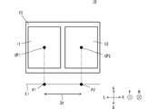
- FIG. 1 is a plan view of the sensor unit 10 with the seat 13 according to the first embodiment laid out flat.
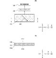
- 2A and 2B are a plan view and a cross-sectional view of the first sensor unit 11 in a state in which the seat 13 according to the first embodiment is laid flat.
- 3A and 3B are a plan view and a cross-sectional view of the second sensor unit 12 in a state in which the seat 13 according to the first embodiment is laid flat.
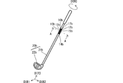
- FIG. 4 is a perspective view of the sensor unit 10 attached to the shaft 21 according to the first embodiment.
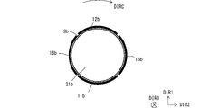
- FIG. 5 is a cross-sectional view along line AA of the sensor unit 10 attached to the shaft 21 according to the first embodiment.
- FIG. 6 is a plan view of the sensor unit 10a with the sheet 13a according to the first modified example unfolded on the plane.
- FIG. 7 is a plan view of the sensor unit 10b in which the seat 13b according to the second embodiment is laid out flat.
- 8A and 8B are a plan view and a cross-sectional view of the third sensor portion 15b in a state in which the seat 13b according to the second embodiment is laid flat.
- 9A and 9B are a plan view and a cross-sectional view of the fourth sensor portion 16b in a state in which the seat 13b according to the second embodiment is laid flat.
- FIG. 10 is a perspective view of the sensor unit 10b attached to the shaft 21b according to the second embodiment.
- FIG. 11 is a cross-sectional view along line AA of the sensor unit 10b attached to the shaft 21b according to the second embodiment.
- FIG. 12 is a plan view of the sensor unit 10c with the sheet 13c according to the second modified example unfolded on the plane.
- FIG. 13 is a plan view of the sensor unit 10d with the seat 13d according to the third embodiment unfolded.
- 14A and 14B are a plan view and a cross-sectional view of the fifth sensor portion 18d in a state in which the seat 13d according to the third embodiment is laid flat.
- FIG. 15 is a perspective view of the sensor unit 10d attached to the shaft 21d according to the third embodiment.
- FIG. 16 is a cross-sectional view along line AA of the sensor unit 10d attached to the shaft 21d according to the third embodiment.
- FIG. 1 is a plan view of the sensor unit 10 with the seat 13 according to the first embodiment laid out flat.
- 2A and 2B are a plan view and a cross-sectional view of the first sensor unit 11 in a state in which the seat 13 according to the first embodiment is laid flat.
- 3A and 3B are a plan view and a cross-sectional view of the second sensor unit 12 in a state in which the seat 13 according to the first embodiment is laid flat.
- FIG. 4 is a perspective view of the sensor unit 10 attached to the shaft 21 according to the first embodiment.
- FIG. 5 is a cross-sectional view along line AA of the sensor unit 10 attached to the shaft 21 according to the first embodiment.
- the sensor unit 10 is a sensor unit that detects deformation of the shaft 21, which will be described later.
- the sensor unit 10 includes a first sensor section 11, a second sensor section 12 and a seat 13.
- the first sensor section 11 and the second sensor section 12 are arranged in this order from left to right.
- the first sensor unit 11 detects deformation of the shaft 21, which will be described later, and includes the shape of the film.
- the first sensor section 11 includes a front main surface and a rear main surface. As shown in FIG. 2, the first sensor section 11 includes a piezoelectric film 113, a first electrode 114a, a second electrode 114b, a charge amplifier 115 and a voltage amplifier circuit .
- the piezoelectric film 113 is an example of a piezoelectric body.
- the piezoelectric film 113 has a film shape. Therefore, the piezoelectric film 113 (first piezoelectric body) includes a front main surface S111 (first piezoelectric body first main surface) and a rear main surface S112 (first piezoelectric body second main surface).
- the main surface of the piezoelectric film 113 (first piezoelectric body) is in a state where the piezoelectric film 113 (first piezoelectric body) is unfolded on a plane, and viewed in the direction normal to the main surface of the sheet 13 (first sheet), It has a rectangular shape.
- the front main surface S111 and the rear main surface S112 of the piezoelectric film 113 are arranged vertically when viewed in the front-rear direction. It has a rectangular shape with long sides extending vertically and short sides extending in the left-right direction.
- the longitudinal direction of the piezoelectric film 113 (first piezoelectric body) is the vertical direction
- the lateral direction of the piezoelectric film 113 (first piezoelectric body) is the horizontal direction.
- the piezoelectric film 113 is a PLA film.
- the second sensor unit 12 detects deformation of the shaft 21, which will be described later, and includes the shape of the film. However, the direction of deformation of the shaft 21 described below detected by the first sensor unit 11 and the direction of deformation of the shaft 21 described below detected by the second sensor unit 12 are the same direction.
- the second sensor section 12 includes a front main surface and a rear main surface. As shown in FIG. 3, the second sensor section 12 includes a piezoelectric film 123, a third electrode 124a and a fourth electrode 124b.
- the piezoelectric film 123 is an example of a piezoelectric body.
- the piezoelectric film 123 has a film shape. Therefore, the piezoelectric film 123 (second piezoelectric body) includes a front main surface S121 (second piezoelectric body first main surface) and a rear main surface S122 (second piezoelectric body second main surface).
- the main surface of the piezoelectric film 123 (second piezoelectric body) is in a state where the piezoelectric film 123 (second piezoelectric body) is unfolded on a plane, and when viewed in the direction normal to the main surface of the sheet 13 (first sheet), It has a rectangular shape.
- the front main surface S121 and the rear main surface S122 of the piezoelectric film 123 are arranged vertically when viewed in the front-rear direction. It has a rectangular shape with long sides extending vertically and short sides extending in the left-right direction.
- the longitudinal direction of the piezoelectric film 123 (second piezoelectric body) is the vertical direction
- the lateral direction of the piezoelectric film 123 (second piezoelectric body) is the horizontal direction.
- the piezoelectric film 123 is a PLA film. The piezoelectric film 113 and the piezoelectric film 123 are described in more detail below.
- the piezoelectric film 113 and the piezoelectric film 123 generate an electric charge according to the differential value of the deformation amount of the piezoelectric film 113 and the piezoelectric film 123, respectively.
- the polarity of the charge generated when the piezoelectric film 113 and the piezoelectric film 123 are stretched in the vertical direction is opposite to the polarity of the charge generated when the piezoelectric film 113 and the piezoelectric film 123 are stretched in the horizontal direction.
- piezoelectric film 113 and piezoelectric film 123 are each films formed from chiral polymers.
- a chiral polymer is, for example, polylactic acid (PLA), particularly L-type polylactic acid (PLLA).
- a PLLA composed of a chiral polymer has a helical structure in its main chain.
- PLLA is uniaxially stretched and has piezoelectricity in which the molecules are oriented.
- Piezoelectric film 113 and piezoelectric film 123 each have a piezoelectric constant of d14.
- the uniaxial stretching axis OD1 of the piezoelectric film 113 forms an angle of 45 degrees clockwise with respect to the vertical direction and forms an angle of 45 degrees counterclockwise with respect to the horizontal direction. . That is, the piezoelectric film 113 (first piezoelectric body) is stretched at least uniaxially.
- This 45 degrees includes angles including, for example, about 45 degrees ⁇ 10 degrees. Accordingly, the piezoelectric film 113 generates an electric charge by being deformed such that the piezoelectric film 113 is elongated in the vertical direction or deformed so as to be compressed in the vertical direction.
- the piezoelectric film 113 generates a negative electric charge when deformed, for example, by stretching in the vertical direction.
- the piezoelectric film 113 for example, generates a positive charge when deformed so as to be compressed vertically.
- the magnitude of the charge depends on the differential value of the amount of deformation of the piezoelectric film 113 due to extension or compression.
- the uniaxial stretching axis OD2 of the piezoelectric film 123 forms an angle of 45 degrees counterclockwise with respect to the vertical direction and forms an angle of 45 degrees clockwise with respect to the horizontal direction. . That is, the piezoelectric film 123 (second piezoelectric body) is stretched at least uniaxially. This 45 degrees includes angles including, for example, about 45 degrees ⁇ 10 degrees.
- the uniaxial stretching axis OD1 of the piezoelectric film 113 (first piezoelectric body) is aligned with the uniaxial stretching axis OD2 of the piezoelectric film 123 (second piezoelectric body) in a state in which the sheet 13 (first sheet) is laid flat.
- the piezoelectric film 123 generates an electric charge by being deformed such that the piezoelectric film 123 is stretched in the vertical direction or deformed so as to be compressed in the vertical direction.
- the piezoelectric film 123 for example, generates a positive charge when deformed so as to be stretched in the vertical direction.
- the piezoelectric film 123 for example, generates a negative charge when deformed so as to be compressed vertically.
- the magnitude of the charge depends on the differential value of the amount of deformation of the piezoelectric film 123 due to extension or compression.
- the first electrode 114a is a signal electrode. As shown in FIG. 2, the first electrode 114a is provided on the rear main surface S112 (the second main surface of the first piezoelectric body). The first electrode 114a covers the rear main surface S112.
- the first electrode 114a is, for example, an organic electrode such as ITO (indium tin oxide) or ZnO (zinc oxide), a metal film by vapor deposition or plating, or a printed electrode film by silver paste.
- the second electrode 114b is a ground electrode.
- the second electrode 114b is connected to ground potential.
- the second electrode 114b is provided on the front main surface S111 (the first main surface of the first piezoelectric body).
- the piezoelectric film 113 is positioned between the first electrode 114a and the second electrode 114b.
- the second electrode 114b covers the front main surface S111.
- the second electrode 114b is, for example, an organic electrode such as ITO (indium tin oxide) or ZnO (zinc oxide), a metal film by vapor deposition or plating, or a printed electrode film by silver paste.
- Such a first sensor section 11 is attached to the sheet 13 (first sheet) via an adhesive layer (not shown). More specifically, the adhesive layer has electrical conductivity. Specifically, the adhesive layer fixes the first electrode 114a and the front main surface of the sheet 13 (first sheet). That is, the rear main surface of the first sensor section 11 is fixed to the front main surface of the seat 13 .
- the third electrode 124a is a signal electrode. As shown in FIG. 3, the third electrode 124a is provided on the rear main surface S122 (the second main surface of the second piezoelectric body). The third electrode 124a covers the rear main surface S122.
- the third electrode 124a is, for example, an organic electrode such as ITO (indium tin oxide) or ZnO (zinc oxide), a metal film by vapor deposition or plating, or a printed electrode film by silver paste.
- the fourth electrode 124b is a ground electrode.
- the fourth electrode 124b is connected to ground potential.
- the fourth electrode 124b is provided on the front main surface S121 (first main surface of the second piezoelectric body).
- the piezoelectric film 123 is positioned between the third electrode 124a and the fourth electrode 124b.
- the fourth electrode 124b covers the front main surface S121.
- the fourth electrode 124b is, for example, an organic electrode such as ITO (indium tin oxide) or ZnO (zinc oxide), a metal film by vapor deposition or plating, or a printed electrode film by silver paste.
- Such a second sensor section 12 is attached to the sheet 13 (first sheet) via an adhesive layer (not shown). More specifically, the adhesive layer has electrical conductivity. Specifically, the adhesive layer fixes the third electrode 124a and the front main surface of the sheet 13 (first sheet). That is, the rear main surface of the second sensor section 12 is fixed to the front main surface of the seat 13 .
- the seat 13 is a seat attached to a shaft 21 which will be described later.
- the sheet 13 (first sheet) has conductivity. Thereby, the sheet 13 (first sheet) electrically connects the first electrode 114 a and the third electrode 124 a of the second sensor section 12 . Therefore, the third electrode 124a is connected to the charge amplifier 115 via the first electrode 114a.
- the charge amplifier 115 converts the charges generated by the piezoelectric film 113 and the piezoelectric film 123 into a detection signal, which is a voltage signal, and outputs the detection signal to the voltage amplification circuit 116 .
- the voltage amplification circuit 116 amplifies the detection signal and outputs it.
- Sheet 13 includes a front major surface and a rear major surface.
- the shape of the front and rear main surfaces of the seat 13 is rectangular.
- the front main surface of the seat 13 has a rectangular shape with a left short side extending in the vertical direction, a right short side extending in the vertical direction, an upper long side extending in the horizontal direction, and a lower long side extending in the horizontal direction.
- the rear main surface of the seat 13 has a left short side extending in the vertical direction, a right short side extending in the vertical direction, an upper long side extending in the horizontal direction, and a lower long side extending in the horizontal direction.
- the lengths of the upper and lower long sides of the front principal surface of the sheet 13 and the lengths of the upper and lower long sides of the rear principal surface of the sheet 13 are determined by shafts, which will be described later, with the sheet 13 unfolded flat. 21 is equal to or greater than the length of the circumference of the cross-sectional circle.
- An adhesive layer (not shown) is provided on the rear main surface of the sheet 13 .
- the adhesive layer has insulating properties.
- the front main surface of the first sensor section 11 is arranged at a position that does not overlap the front main surface of the second sensor section 12 when viewed in the front-rear direction. It is That is, the front main surface of the first sensor portion 11 has a portion that does not overlap the front main surface of the second sensor portion 12 when viewed in the front-rear direction when the seat 13 is laid out flat.
- the front main surface of the second sensor section 12 is arranged at a position not overlapping the front main surface of the first sensor section 11 when viewed in the front-rear direction. That is, the front main surface of the second sensor portion 12 has a portion that does not overlap the front main surface of the first sensor portion 11 when viewed in the front-rear direction when the seat 13 is laid out flat.
- a first center point CP1 of the first sensor portion 11 is defined when viewed in the front-rear direction with the seat 13 unfolded on a plane.
- the first center point CP1 is, for example, the center of gravity of the front main surface of the first sensor section 11 .
- the first center point CP1 may be the center of gravity of the rear main surface of the first sensor section 11, for example.
- the first center point CP1 may be, for example, the center of the front main surface of the first sensor section 11 .
- the two diagonal lines intersect at the first center point CP1.
- the first center point CP1 may be, for example, the center of the rear main surface of the first sensor section 11 .
- the two diagonal lines intersect at the first center point CP1.
- a second center point CP2 of the second sensor portion 12 is defined when viewed in the front-rear direction with the seat 13 unfolded on a plane. Since the definition of the second center point CP2 conforms to the definition of the first center point CP1, detailed description thereof will be omitted.
- an arbitrary straight line L1 extending in the left-right direction is defined when viewed in the front-rear direction with the seat 13 unfolded on a plane.
- a first intersection point P1 is defined as an intersection of a perpendicular line drawn from the first center point CP1 to the straight line L1 and the straight line L1 when viewed in the front-rear direction with the seat 13 unfolded on a plane.
- a perpendicular line drawn from the second center point CP2 to the straight line L1 intersects with the straight line L1 is defined as a second intersection point P2.
- a distance between the first intersection point P1 and the second intersection point P2 is defined as a first distance D1.
- the first distance D1 in the present embodiment is equal to half the length of the circumference of the cross-sectional circle of the shaft 21, which will be described later, when the seat 13 is laid flat.
- the golf club 20 includes a shaft 21 and a head 22, as shown in FIG.
- the shape of the shaft 21 is cylindrical.
- the central axis direction of the cylinder is equal to the third direction DIR3. That is, the shaft 21 extends in the third direction DIR3.
- a cross section of the shaft 21 perpendicular to the third direction DIR3 has a circular shape.
- the circumferential direction of the cross-sectional circle of the shaft 21 is equal to the circumferential direction DIRC.
- Shaft 21 has a first end and a second end in third direction DIR3.
- a head 22 is provided at the first end of the shaft 21 .
- a grip is provided near the second end of the shaft 21 .
- the object to be measured is the shaft 21 .
- the sensor unit 10 is attached to the circumferential surface of the shaft 21. Specifically, the rear main surface of the sheet 13 is fixed to the shaft 21 by an adhesive layer (not shown) provided on the rear main surface of the sheet 13 . In the example of FIG. 4, the sensor unit 10 is attached near the grip of the shaft 21, but the attachment position of the sensor unit 10 to the shaft 21 is not limited to this.
- the direction in which the upper long side and the lower long side of the front main surface of the seat 13 extend is equal to the circumferential direction DIRC.
- the direction in which the upper long side and the lower long side of the front main surface of the seat 13 extend is equal to the circumferential direction DIRC.
- the first distance D1 is equal to the distance in the circumferential direction DIRC between the first center point CP1 of the first sensor portion 11 and the second center point CP2 of the second sensor portion 12 .
- the first distance D1 is equal to half the length of the circumference of the cross-sectional circle of the shaft 21 in the state where the sheet 13 is spread out on the plane.
- the first center point CP1 of the first sensor portion 11 and the second center point CP2 of the second sensor portion 12 are arranged 180 degrees apart in the circumferential direction DIRC of the shaft 21 .
- the first sensor section 11 and the second sensor section 12 are positioned in the first direction DIR1.
- 12 is fixed to the shaft 21 so that the shaft 21 is arranged between them.
- the first sensor unit 11 detects deformation of the shaft 21 in the first direction DIR1.
- the second sensor unit 12 detects deformation of the shaft 21 in the first direction DIR1.
- the deformation of the shaft 21 detected by the first sensor unit 11 is the deformation (bending) of the shaft 21 in the first direction DIR1
- the deformation of the shaft 21 detected by the second sensor unit 12 is the deformation of the shaft 21 is deformation (bending) in the first direction DIR1 of .
- the piezoelectric film 113 when the shaft 21 deforms in the first direction DIR1, the piezoelectric film 113 generates charges and the piezoelectric film 123 generates charges according to the deformation of the shaft 21 . That is, the electrical properties of the piezoelectric film 113 and the electrical properties of the piezoelectric film 123 change according to the deformation (first deformation) of the shaft 21 . Since the piezoelectric film 113 is compressed in the vertical direction, it generates positive charges, and the piezoelectric film 123 is stretched in the vertical direction, so it generates positive charges. That is, the polarity of the charges generated by the piezoelectric film 113 and the polarity of the charges generated by the piezoelectric film 123 are the same.
- the piezoelectric film 113 does not generate charges or hardly generates charges, and the piezoelectric film 123 does not generate charges according to the deformation of the shaft 21 . Or generate little charge. That is, the electrical properties of the piezoelectric film 113 and the electrical properties of the piezoelectric film 123 do not change or hardly change according to the deformation (second deformation) of the shaft 21 .
- a cross section of shaft 21 perpendicular to third direction DIR3 has a circular shape.
- the first sensor unit 11 and the second sensor unit 12 are attached to the shaft 21 so that the shaft 21 is arranged between the first sensor unit 11 and the second sensor unit 12 in the first direction DIR1. , is fixed to the shaft 21 .
- the electrical characteristics of the first sensor unit 11 and the electrical characteristics of the second sensor unit 12 change according to the deformation of the shaft 21 . Accordingly, when the shaft 21 is deformed (bent) in the first direction DIR1, the piezoelectric film 113 is compressed and the piezoelectric film 123 is expanded, and both the piezoelectric film 113 and the piezoelectric film 123 generate charges.
- the potential of the detection signal of the first sensor section 11 changes, and the potential of the detection signal of the second sensor section 12 changes.
- the detection signal of the first sensor section 11 and the detection signal of the second sensor section 12 can be used to detect the deformation of the shaft 21 .
- the deformation detection accuracy of the shaft 21 can be improved.
- the detection signals of the first sensor section 11 and the second sensor section 12 can be easily generated. More specifically, the uniaxial stretching axis OD1 of the piezoelectric film 113 (first piezoelectric body) forms an angle of 45 degrees clockwise with respect to the vertical direction and forms an angle of 45 degrees counterclockwise with respect to the horizontal direction. forming The uniaxial stretching axis OD2 of the piezoelectric film 123 (second piezoelectric body) forms an angle of 45 degrees counterclockwise with respect to the vertical direction and forms an angle of 45 degrees clockwise with respect to the horizontal direction. .
- the uniaxial stretching axis OD1 of the piezoelectric film 113 (first piezoelectric body) is aligned with the uniaxial stretching axis OD2 of the piezoelectric film 123 (second piezoelectric body) in a state in which the sheet 13 (first sheet) is laid flat. form an angle of 90 degrees clockwise.
- the detection signal can be generated by adding the charges generated by the piezoelectric film 113 and the charges generated by the piezoelectric film 123 .
- the detection signals of the first sensor unit 11 and the second sensor unit 12 can be easily generated.
- the sheet 13 (first sheet) electrically connects the first electrode 114a and the third electrode 124a.
- the detection signals of the first sensor section 11 and the second sensor section 12 can be generated by one charge amplifier 115 and one voltage amplifier circuit 116 .
- the circuit configuration of the sensor unit 10 is simplified.
- FIG. 6 is a plan view of the sensor unit 10a with the sheet 13a according to the first modified example unfolded on the plane.
- the sensor unit 10a according to the first modified example only the portions that differ from the arrangement structure of the sensor unit 10 according to the first embodiment will be described, and the rest will be omitted.
- the sensor unit 10a further includes a seat 14a.
- the sheet 13a first sheet
- the sheet 14a second sheet
- the seat 14a has a strip shape extending in the left-right direction when viewed in the front-rear direction.
- the sheet 14a is attached to the first sensor portion 11a and the second sensor portion 12a.
- the sheet 14a (second sheet) electrically connects the first electrode 114a and the third electrode 124a.
- the left portion of the sheet 14a is attached to the top of the first electrode 114a.
- the right portion of the sheet 14a is attached to the top of the third electrode 124a.
- the sheet 14a electrically connects the first electrode 114a and the third electrode 124a, but the sheet 14a electrically connects the second electrode 114b and the fourth electrode 124b.
- the sensor unit 10a may further include a conductive sheet 14e, and the first sensor section 11a and the second sensor section 12a may be connected by the sheet 14e.
- the sheet 14a may connect the first electrode 114a and the third electrode 124a
- the sheet 14e may connect the second electrode 114b and the fourth electrode 124b. That is, the sheet 14a (second sheet) electrically connects the first electrode 114a and the third electrode 124a, and the sheet 14e (third sheet) electrically connects the second electrode 114b and the fourth electrode 124b. may be connected to
- FIG. 7 is a plan view of the sensor unit 10b in which the seat 13b according to the second embodiment is laid out flat.
- 8A and 8B are a plan view and a cross-sectional view of the third sensor portion 15b in a state in which the seat 13b according to the second embodiment is laid flat.
- 9A and 9B are a plan view and a cross-sectional view of the fourth sensor portion 16b in a state in which the seat 13b according to the second embodiment is laid flat.
- FIG. 10 is a perspective view of the sensor unit 10b attached to the shaft 21b according to the second embodiment.
- FIG 11 is a cross-sectional view along line AA of the sensor unit 10b attached to the shaft 21b according to the second embodiment.
- the sensor unit 10b according to the second embodiment only the parts that differ from the arrangement structure of the sensor unit 10 according to the first embodiment will be described, and the rest will be omitted.
- the sensor unit 10b further includes a seat 14b, a third sensor portion 15b, a fourth sensor portion 16b and a seat 17b.
- the first sensor portion 11b, the second sensor portion 12b, the third sensor portion 15b, and the fourth sensor portion 16b are arranged in this order from left to right.
- the sheet 13b (first sheet) has insulating properties.
- Sheet 14b (second sheet) and sheet 17b (fourth sheet) are conductive.
- the third sensor section 15b detects deformation of the shaft 21b, which is the object to be measured, including the shape of the film.
- the deformation direction (first direction) of the shaft 21b, which is the object to be measured, detected by the first sensor portion 11b and the second sensor portion 12b and the deformation of the shaft 21b, which is the object to be measured, detected by the third sensor portion 15b is a different direction from the direction of (second direction).
- the third sensor portion 15b includes a front main surface and a rear main surface.
- the third sensor section 15b includes a piezoelectric film 153, a fifth electrode 154a, a sixth electrode 154b, a charge amplifier 155 and a voltage amplifier circuit 156.
- the piezoelectric film 153 is an example of a piezoelectric body.
- the piezoelectric film 153 has a film shape. Therefore, the piezoelectric film 153 (third piezoelectric body) includes a front main surface S151 (third piezoelectric body first main surface) and a rear main surface S152 (third piezoelectric body second main surface).
- the main surface of the piezoelectric film 153 (third piezoelectric body) is in a state where the piezoelectric film 153 (third piezoelectric body) is unfolded on a plane, and when viewed in the direction normal to the main surface of the sheet 13b (first sheet), It has a rectangular shape.
- the front main surface S151 and the rear main surface S152 of the piezoelectric film 153 extend vertically when viewed in the front-rear direction. It has a rectangular shape with long sides extending vertically and short sides extending in the left-right direction.
- the longitudinal direction of the piezoelectric film 153 (third piezoelectric body) is the vertical direction
- the lateral direction of the piezoelectric film 153 (third piezoelectric body) is the horizontal direction.
- the piezoelectric film 153 is a PLA film.
- the PLA film is the same as in the first embodiment, and the description is omitted.
- the uniaxial stretching axis OD3 of the piezoelectric film 153 forms an angle of 45 degrees clockwise with respect to the vertical direction, and an angle of 45 degrees counterclockwise with respect to the horizontal direction. forming That is, the piezoelectric film 153 (third piezoelectric body) is stretched at least uniaxially.
- This 45 degrees includes angles including, for example, about 45 degrees ⁇ 10 degrees.
- the fifth electrode 154a, the sixth electrode 154b, the charge amplifier 155, and the voltage amplification circuit 156 have the same structure as the first electrode 114a, the second electrode 114b, the charge amplifier 115, and the voltage amplification circuit 116, so description thereof is omitted. do.
- Such a third sensor section 15b is attached to the sheet 13b (first sheet) via an adhesive layer (not shown). Specifically, the adhesive layer fixes the fifth electrode 154a and the front main surface of the sheet 13b (first sheet). That is, the rear main surface of the third sensor portion 15b is fixed to the front main surface of the seat 13b.
- the fourth sensor section 16b detects deformation of the shaft 21b, which is the object to be measured, including the shape of the film. However, the direction of deformation of the shaft 21b, which is the object to be measured, detected by the third sensor portion 15b and the direction of deformation of the shaft 21b, which is the object to be measured, detected by the fourth sensor portion 16b are the same direction.
- the fourth sensor portion 16b includes a front main surface and a rear main surface.
- the fourth sensor section 16b includes a piezoelectric film 163, a seventh electrode 164a and an eighth electrode 164b.
- the piezoelectric film 163 is an example of a piezoelectric body.
- the piezoelectric film 163 has a film shape. Therefore, the piezoelectric film 163 (fourth piezoelectric body) includes a front main surface S161 (fourth piezoelectric body first main surface) and a rear main surface S162 (fourth piezoelectric body second main surface).
- the main surface of the piezoelectric film 163 (fourth piezoelectric body) is in a state where the piezoelectric film 163 (fourth piezoelectric body) is unfolded on a plane, and viewed in the direction normal to the main surface of the sheet 13b (first sheet), It has a rectangular shape.
- the front main surface S161 and the rear main surface S162 of the piezoelectric film 163 are arranged vertically when viewed in the front-rear direction. It has a rectangular shape with long sides extending vertically and short sides extending in the left-right direction.
- the longitudinal direction of the piezoelectric film 163 (piezoelectric body) of the fourth sensor section 16b is the vertical direction
- the lateral direction of the piezoelectric film 163 (piezoelectric body) of the fourth sensor section 16b is the horizontal direction.
- the piezoelectric film 163 is a PLA film.
- the PLA film is the same as in the first embodiment, and the description is omitted.
- the uniaxial stretching axis OD4 of the piezoelectric film 163 forms an angle of 45 degrees counterclockwise with respect to the vertical direction and an angle of 45 degrees clockwise with respect to the horizontal direction. forming That is, the piezoelectric film 163 (fourth piezoelectric body) is stretched at least uniaxially.
- This 45 degrees includes angles including, for example, about 45 degrees ⁇ 10 degrees.
- the uniaxial stretching axis OD3 of the piezoelectric film 153 is aligned with the uniaxial stretching axis OD4 of the piezoelectric film 163 (fourth piezoelectric body) in a state in which the sheet 13b (first sheet) is laid flat. form an angle of 90 degrees clockwise.
- This 90 degrees includes angles including, for example, about 90 degrees ⁇ 10 degrees.
- the seventh electrode 164a and the eighth electrode 164b have the same structure as the first electrode 114a and the second electrode 114b, description thereof is omitted.
- Such a fourth sensor portion 16b is attached to the sheet 13b (first sheet) via an adhesive layer (not shown). Specifically, the adhesive layer fixes the seventh electrode 164a and the front main surface of the sheet 13b (first sheet). That is, the rear main surface of the fourth sensor portion 16b is fixed to the front main surface of the seat 13b.
- the seat 14b (second seat) is attached to the first sensor portion 11b and the second sensor portion 12b.
- the sheet 14b (second sheet) electrically connects the first electrode 114a and the third electrode 124a.
- the left portion of sheet 14b is attached to the top of first electrode 114a.
- the right portion of the sheet 14b is attached to the top of the third electrode 124a.
- the sheet 17b (fourth sheet) is attached to the third sensor section 15b and the fourth sensor section 16b. Specifically, the sheet 17b (fourth sheet) electrically connects the fifth electrode 154a and the seventh electrode 164a. The left portion of the sheet 17b is attached to the lower portion of the fifth electrode 154a. The right portion of the sheet 17b is attached to the lower portion of the seventh electrode 164a.
- the front main surface of the third sensor portion 15b is arranged at a position not overlapping the front main surface of the fourth sensor portion 16b when viewed in the front-rear direction. It is That is, the front main surface of the third sensor portion 15b has a portion that does not overlap the front main surface of the fourth sensor portion 16b when viewed in the front-rear direction when the seat 13b is unfolded flat.
- the front main surface of the fourth sensor portion 16b is arranged at a position not overlapping the front main surface of the third sensor portion 15b when viewed in the front-rear direction. That is, the front main surface of the fourth sensor portion 16b has a portion that does not overlap the front main surface of the third sensor portion 15b when viewed in the front-rear direction when the seat 13b is unfolded flat.
- the upper long sides and lower long sides of the front main surface of the sheet 13b, the short sides of the first sensor portion 11b, the short sides of the second sensor portion 12b, and the third sensor portion are measured.
- the short side of 15b and the short side of the fourth sensor portion 16b are parallel to each other.
- a third center point CP3b of the third sensor portion 15b and a fourth center point CP4b of the fourth sensor portion 16b are defined when viewed in the front-rear direction with the seat 13b unfolded on a plane.
- the definition of the third center point CP3b and the definition of the fourth center point CP4b conform to the definition of the first center point CP1, so detailed description thereof will be omitted.
- a perpendicular line drawn from the third center point CP3b to the straight line L1 and the straight line L1 intersect when viewed in the front-rear direction is defined as a third intersection point P3b.
- a perpendicular line drawn from the fourth center point CP4b to the straight line L1 intersects with the straight line L1 is defined as a fourth intersection point P4b.
- a distance between the third intersection point P3b and the fourth intersection point P4b is defined as a second distance D2b.
- the distance between the first intersection point P1b and the third intersection point P3b is defined as a third distance D3b. Also, the distance between the first intersection point P1b and the fourth intersection point P4b is defined as D4b. Also, the distance between the second intersection point P2b and the third intersection point P3b is defined as D5b. Also, the distance between the second intersection point P2b and the fourth intersection point P4b is defined as D6b.
- the first distance D1b in this embodiment is equal to 1/2 of the length of the circumference of the cross-sectional circle of the shaft 21b, which is the object to be measured, when the sheet 13b is unfolded on a plane.
- the second distance D2b is equal to half the length of the circumference of the cross-sectional circle of the shaft 21b, which is the object to be measured, in the state where the sheet 13b is unfolded on the plane.
- the third distance D3b in the present embodiment is equal to 1/4 of the length of the circumference of the cross-sectional circle of the shaft 21b, which is the object to be measured, when the sheet 13b is unfolded on the plane.
- the fourth distance D4b in this embodiment is equal to three-fourths of the length of the circumference of the cross-sectional circle of the shaft 21b, which is the object to be measured, when the sheet 13b is unfolded on the plane.
- the fifth distance D5b in this embodiment is equal to 1/4 of the length of the circumference of the cross-sectional circle of the shaft 21b, which is the object to be measured, when the sheet 13b is unfolded on a plane.
- the sixth distance D6b in the present embodiment is equal to 1/4 of the length of the circumference of the cross-sectional circle of the shaft 21b, which is the object to be measured, in the state in which the sheet 13b is unfolded on the plane.
- the sensor unit 10b is attached to the circumferential surface of the shaft 21b.
- the rear main surface of the sheet 13b is fixed to the shaft 21b by an adhesive layer (not shown) provided on the rear main surface of the sheet 13b.
- the second distance D2b is equal to half the length of the circumference of the cross-sectional circle of the shaft 21b when the seat 13b is laid out flat.
- the third center point CP3b of the third sensor portion 15b and the fourth center point CP4b of the fourth sensor portion 16b are arranged 180 degrees apart in the circumferential direction DIRC of the shaft 21b. That is, as shown in FIG.
- the third sensor portion 15b and the fourth sensor portion 16b are in the second direction DIR2. It is fixed to the shaft 21b so that the shaft 21b is arranged between the shaft 21b and 16b. Thereby, the third sensor portion 15b detects deformation of the shaft 21b in the second direction DIR2. Similarly, the fourth sensor portion 16b detects deformation of the shaft 21b in the second direction DIR2.
- the deformation of the shaft 21b detected by the third sensor unit 15b is the deformation (bending) of the shaft 21b in the second direction DIR2
- the deformation of the shaft 21b detected by the fourth sensor unit 16b is the deformation of the shaft 21b. is deformation (bending) in the second direction DIR2 of .
- the third distance D3b is equal to 1/4 of the length of the circumference of the cross-sectional circle of the shaft 21b when the seat 13b is unfolded on the plane.
- the first center point CP1b of the first sensor portion 11b and the third center point CP3b of the third sensor portion 15b are arranged 90 degrees apart in the circumferential direction DIRC of the shaft 21b. That is, the first direction DIR1 and the second direction DIR2 are directions that differ by 90 degrees when viewed from the third direction DIR3.
- the piezoelectric film 113 when the shaft 21b is deformed in the first direction DIR1, the piezoelectric film 113 generates charges and the piezoelectric film 123 generates charges according to the deformation of the shaft 21b. That is, the electrical properties of the piezoelectric film 113 and the electrical properties of the piezoelectric film 123 change according to the deformation (first deformation) of the shaft 21b. Since the piezoelectric film 113 is compressed in the vertical direction, it generates positive charges, and the piezoelectric film 123 is stretched in the vertical direction, so it generates positive charges. That is, the polarity of the charges generated by the piezoelectric film 113 and the polarity of the charges generated by the piezoelectric film 123 are the same.
- the piezoelectric film 153 does not generate an electric charge or hardly generates an electric charge, and the piezoelectric film 163 does not generate an electric charge, depending on the deformation of the shaft 21b. Or generate little charge. That is, the electrical properties of the piezoelectric film 153 and the electrical properties of the piezoelectric film 163 do not change or hardly change according to the deformation (first deformation) of the shaft 21b.
- the piezoelectric film 153 when the shaft 21b is deformed in the second direction DIR2, the piezoelectric film 153 generates charges and the piezoelectric film 163 generates charges according to the deformation of the shaft 21b. That is, the electrical properties of the piezoelectric film 153 and the electrical properties of the piezoelectric film 163 change according to the deformation (second deformation) of the shaft 21b. Since the piezoelectric film 153 is stretched in the vertical direction, it generates negative charges, and the piezoelectric film 163 is compressed in the vertical direction, so it generates negative charges. That is, the polarity of the charges generated by the piezoelectric film 153 and the polarity of the charges generated by the piezoelectric film 163 are the same.
- the piezoelectric film 113 does not generate electric charges or hardly generates electric charges, and the piezoelectric film 123 does not generate electric charges according to the deformation of the shaft 21b. Or generate little charge. That is, the electrical properties of the piezoelectric film 113 and the electrical properties of the piezoelectric film 123 do not change or hardly change according to the deformation (second deformation) of the shaft 21b.
- a cross section of the shaft 21b perpendicular to the third direction DIR3 has a circular shape.
- the electrical characteristics of the third sensor portion 15b and the electrical characteristics of the fourth sensor portion 16b change according to the deformation of the shaft 21b. Accordingly, when the shaft 21b is deformed (bent) in the second direction DIR2, the piezoelectric film 153 is compressed, the piezoelectric film 163 is expanded, and both the piezoelectric film 153 and the piezoelectric film 163 generate charges. Therefore, the potential of the detection signal of the third sensor section 15b changes, and the potential of the detection signal of the fourth sensor section 16b changes. Thereby, the detection signal of the third sensor portion 15b and the detection signal of the fourth sensor portion 16b can be used to detect the deformation of the shaft 21b. As a result, according to the sensor unit 10b, the deformation detection accuracy of the shaft 21b can be improved.
- the uniaxial stretching axis OD3 of the piezoelectric film 153 forms an angle of 45 degrees clockwise with respect to the vertical direction and an angle of 45 degrees counterclockwise with respect to the horizontal direction.
- the uniaxial stretching axis OD4 of the piezoelectric film 163 forms an angle of 45 degrees counterclockwise with respect to the vertical direction and forms an angle of 45 degrees clockwise with respect to the horizontal direction.
- the uniaxial stretching axis OD3 of the piezoelectric film 153 (third piezoelectric body) is aligned with the uniaxial stretching axis OD4 of the piezoelectric film 163 (fourth piezoelectric body) in a state in which the sheet 13 (first sheet) is unfolded on a plane. form an angle of 90 degrees clockwise.
- the shaft 21b is deformed (bent) in the second direction DIR2
- the polarity of the charge generated by the piezoelectric film 153 and the polarity of the charge generated by the piezoelectric film 163 become the same.
- the detection signal can be generated by adding the charges generated by the piezoelectric film 153 and the charges generated by the piezoelectric film 163 . As a result, it becomes easier to generate the detection signals of the third sensor section 15b and the fourth sensor section 16b.
- the sheet 17b (fourth sheet) electrically connects the fifth electrode 154a and the seventh electrode 164a.
- one charge amplifier 155 and one voltage amplifier circuit 156 can generate the detection signals of the third sensor section 15b and the fourth sensor section 16b.
- the circuit configuration of the sensor unit 10b is simplified.
- the sheet 17b electrically connects the fifth electrode 154a and the seventh electrode 164a, but the sheet 17b electrically connects the sixth electrode 154b and the eighth electrode 164b.
- the sensor unit 10b may further include a conductive sheet 17e, and the third sensor section 15b and the fourth sensor section 16b may be connected by the sheet 17e.
- the sheet 17b may connect the fifth electrode 154a and the seventh electrode 164a
- the sheet 17e may connect the sixth electrode 154b and the eighth electrode 164b. That is, the sheet 17b (fourth sheet) electrically connects the fifth electrode 154a and the seventh electrode 164a, and the sheet 17e (fifth sheet) electrically connects the sixth electrode 154b and the eighth electrode 164b. may be connected to
- FIG. 12 is a plan view of the sensor unit 10c with the sheet 13c according to the second modified example unfolded on the plane.
- the sensor unit 10c according to the second modified example only the parts that differ from the arrangement structure of the sensor unit 10b according to the second embodiment will be described, and the rest will be omitted.
- the first sensor section 11c and the second sensor section 12c are arranged in this order from left to right when the seat 13c is unfolded on a plane.
- the third sensor portion 15c and the fourth sensor portion 16c are arranged in this order from left to right.
- the left portion of the third sensor portion 15c is positioned below the right portion of the first sensor portion 11c.
- the right portion of the third sensor portion 15c is positioned below the left portion of the second sensor portion 12c.
- the left portion of the fourth sensor portion 16c is positioned below the right portion of the second sensor portion 12c.
- the first sensor portion 11c has a portion that overlaps the third sensor portion 15c when viewed in the vertical direction when the seat 13c is unfolded flat.
- the second sensor portion 12c has portions overlapping the third sensor portion 15c and the fourth sensor portion 16c when viewed in the vertical direction.
- the third sensor portion 15c has a portion overlapping the first sensor portion 11c and the second sensor portion 12c when viewed in the vertical direction.
- the fourth sensor portion 16c has a portion that overlaps the second sensor portion 12c when viewed in the vertical direction.
- the sensor unit 10c as described above also has the same effects as the sensor unit 10b.
- the first sensor portion 11c , the second sensor portion 12c, the third sensor portion 15c, and the fourth sensor portion 16c can be increased, the first sensor portion 11c , the second sensor portion 12c, the third sensor portion 15c, and the fourth sensor portion 16c can be enlarged.
- the voltage fluctuations of the detection signals of the first sensor section 11c and the second sensor section 12c increase.
- the voltage fluctuations of the detection signals of the third sensor section 15c and the fourth sensor section 16c increase.
- the detection accuracy of the sensor unit 10c can be improved.
- FIG. 13 is a plan view of the sensor unit 10d with the seat 13d according to the third embodiment unfolded.
- 14A and 14B are a plan view and a cross-sectional view of the fifth sensor portion 18d in a state in which the seat 13d according to the third embodiment is laid flat.
- FIG. 15 is a perspective view of the sensor unit 10d attached to the shaft 21d according to the third embodiment.
- FIG. 16 is a cross-sectional view along line AA of the sensor unit 10d attached to the shaft 21d according to the third embodiment.
- the sensor unit 10d according to the third embodiment only the parts that differ from the arrangement structure of the sensor unit 10 according to the first embodiment will be described, and the rest will be omitted.
- the sensor unit 10d further includes a fifth sensor section 18d and a seat 19d.
- the first sensor portion 11d and the fifth sensor portion 18d are arranged in this order from front to back.
- the fifth sensor section 18d detects deformation of the shaft 21d, which is the object to be measured, including the shape of the film. However, the direction of deformation of the shaft 21d as the object to be measured detected by the first sensor portion 11d and the second sensor portion 12d and the direction of deformation of the shaft 21d as the object to be measured detected by the fifth sensor portion 18d are in the same direction.
- the fifth sensor portion 18d includes a front main surface and a rear main surface. Also, the area of the front main surface of the fifth sensor portion 18d is smaller than the area of the front main surface of the first sensor portion 11d.
- the fifth sensor section 18d includes a piezoelectric film 183, a ninth electrode 184a, a tenth electrode 184b, a charge amplifier 185 and a voltage amplifier circuit 186.
- the piezoelectric film 183 is an example of a piezoelectric body.
- the piezoelectric film 183 has a film shape. Accordingly, the piezoelectric film 183 includes a front major surface S181 and a rear major surface S182.
- the main surface of the piezoelectric film 183 (fifth piezoelectric body) is in a state where the piezoelectric film 183 (fifth piezoelectric body) is unfolded on a plane, and viewed in the direction normal to the main surface of the sheet 13d (first sheet), It has a rectangular shape.
- the front main surface S181 and the rear main surface S182 of the piezoelectric film 183 are arranged vertically when viewed in the front-rear direction. It has a rectangular shape with long sides extending vertically and short sides extending in the left-right direction.
- the longitudinal direction of the piezoelectric film 183 (fifth piezoelectric body) is the vertical direction
- the lateral direction of the piezoelectric film 183 (fifth piezoelectric body) is the horizontal direction.
- the piezoelectric film 183 is a PLA film.
- the PLA film is the same as in the first embodiment, and the description is omitted.
- the uniaxial stretching axis OD5 of the piezoelectric film 183 (fifth piezoelectric body) forms an angle of 45 degrees clockwise with respect to the vertical direction, and an angle of 45 degrees counterclockwise with respect to the horizontal direction. forming That is, the piezoelectric film 183 (fifth piezoelectric body) is stretched at least uniaxially.
- the uniaxial stretching axis OD5 of the piezoelectric film 183 (fifth piezoelectric body) and the uniaxial stretching axis OD1 of the piezoelectric film 113 (first piezoelectric body) are in the same direction.
- the ninth electrode 184a, the tenth electrode 184b, the charge amplifier 185 and the voltage amplification circuit 186 have the same structure as the first electrode 114a, the second electrode 114b, the charge amplifier 115 and the voltage amplification circuit 116, so the description is omitted. do.
- Such a fifth sensor section 18d is attached to the sheet 19d (sixth sheet) via an adhesive layer (not shown). Specifically, the adhesive layer fixes the ninth electrode 184a and the front main surface of the sheet 19d. That is, the rear main surface of the fifth sensor portion 18d is fixed to the front main surface of the seat 19d.
- the fifth sensor section 18d is attached to the sheet 13d via an adhesive layer (not shown).
- the adhesive layer has insulating properties. Specifically, the tenth electrode 184b and the rear main surface of the sheet 13d are fixed. That is, the front main surface of the fifth sensor portion 18d is fixed to the rear main surface of the seat 13d.
- the seat 19d is a seat attached to the shaft 21d, which is the object to be measured.
- the sheet 19d (sixth sheet) has insulating properties.
- Sheet 19d includes a front major surface and a rear major surface.
- the shape of the front and rear main surfaces of the seat 19d is rectangular.
- the front main surface of the seat 19d has a rectangular shape with a left short side extending in the vertical direction, a right short side extending in the vertical direction, an upper long side extending in the horizontal direction, and a lower long side extending in the horizontal direction.
- the rear main surface of the seat 19d has a left short side extending in the vertical direction, a right short side extending in the vertical direction, an upper long side extending in the horizontal direction, and a lower long side extending in the horizontal direction.
- the length of the upper long side and the lower long side of the front main surface of the sheet 19d is shorter than the length of the upper long side and the lower long side of the front main surface of the sheet 13d.
- the left short side and right short side of the front main surface of the sheet 19d are shorter than the left short side and right short side of the front main surface of the sheet 13d.
- the sheet 19d (sixth sheet) is attached to the sheet 13d (first sheet) via an adhesive layer (not shown). More specifically, the adhesive layer has insulating properties. Specifically, the adhesive layer fixes a portion of the front major surface of sheet 19d and the rear major surface of sheet 13d.
- a portion of the front main surface of the seat 19d is a portion where the front main surface of the seat 19d and the front main surface of the fifth sensor portion 18d do not overlap when viewed in the front-rear direction when the seat 19d is unfolded flat.
- it is a portion where the rear main surface of the seat 13d and the front main surface of the seat 19d overlap. That is, a portion of the front main surface of the seat 19d is fixed to a portion of the rear main surface of the seat 13d.
- the left short side and right short side of the front main surface of the sheet 13d, the long side of the first sensor portion 11d (first piezoelectric The longitudinal direction of the body), the long side of the second sensor portion 12d (longitudinal direction of the second piezoelectric body), and the long side of the fifth sensor portion 18d (longitudinal direction of the fifth piezoelectric body) are parallel to each other.
- the upper long side and the lower long side of the front main surface of the sheet 13d, the short side of the first sensor portion 11d, the short side of the second sensor portion 12d, and the fifth sensor portion 12d are parallel to each other.
- a fifth center point CP5d of the fifth sensor portion 18d is defined when viewed in the front-rear direction with the seat 13d unfolded on a plane. Note that the definition of the fifth center point CP5d conforms to the definition of the first center point CP1, so detailed description thereof will be omitted.
- the first center point CP1d of the first sensor portion 11d and the fifth center point CP5d of the fifth sensor portion 18d in this embodiment match.
- the front main surface of the fifth sensor portion 18d has a portion that overlaps the front main surface of the first sensor portion 11d when viewed in the front-rear direction with the seat 13d unfolded flat.
- the sensor unit 10d is attached to the circumferential surface of the shaft 21d. Specifically, a portion of the rear main surface of the seat 13d and a portion of the rear main surface of the seat 19d are provided on a portion of the rear main surface of the seat 13d and a portion of the rear main surface of the seat 19d. It is fixed to the shaft 21d by an adhesive layer (not shown). With the sensor unit 10d attached to the shaft 21d, the fifth sensor portion 18d is fixed to the shaft 21d so as to be arranged between the first sensor portion 11d and the shaft 21d in the first direction DIR1. .
- the fifth sensor portion 18d detects deformation of the shaft 21d in the first direction DIR1, like the first sensor portion 11d and the second sensor portion 12d.
- the deformation of the shaft 21d detected by the first sensor portion 11d, the second sensor portion 12d, and the fifth sensor portion 18d is the deformation (bending) of the shaft 21d in the first direction DIR1.
- the polarity of the charge generated by the piezoelectric film 183 of the fifth sensor portion 18d and the polarity of the charge generated by the piezoelectric film 113 of the first sensor portion 11d and the piezoelectric film 123 of the second sensor portion 12d are the same.
- the piezoelectric film 113 when the shaft 21d is deformed in the first direction DIR1, the piezoelectric film 113 generates charges, the piezoelectric film 123 generates charges, and the piezoelectric film 183 generates charges according to the deformation of the shaft 21d. do. That is, the electrical properties of the piezoelectric film 113, the electrical properties of the piezoelectric film 123, and the electrical properties of the piezoelectric film 183 change according to the deformation of the shaft 21d.
- the piezoelectric film 113 since the piezoelectric film 113 is compressed in the vertical direction, it generates a positive charge.
- the piezoelectric film 123 is stretched in the vertical direction, so it generates a positive charge. Because it is compressed, it generates a positive charge. That is, the polarity of the charge generated by the piezoelectric film 113, the polarity of the charge generated by the piezoelectric film 123, and the polarity of the charge generated by the piezoelectric film
- the piezoelectric film 113 does not generate charges or hardly generates charges, and the piezoelectric film 123 does not generate charges according to the deformation of the shaft 21d. Or generate little charge, piezoelectric film 183 generates no charge or little charge. That is, according to the deformation (second deformation) of the shaft 21d, the electrical properties of the piezoelectric film 113, the electrical properties of the piezoelectric film 123, and the electrical properties of the piezoelectric film 183 do not change or hardly change.
- a cross section of the shaft 21d perpendicular to the third direction DIR3 has a circular shape.
- the fifth sensor portion 18d is fixed to the shaft 21d so as to be arranged between the first sensor portion 11d and the shaft 21d in the first direction DIR1 while attached to the shaft 21d.
- the electrical characteristics of the first sensor portion 11d, the electrical characteristics of the second sensor portion 12d, and the electrical characteristics of the fifth sensor portion 18d change according to the deformation of the shaft 21d.
- the piezoelectric films 113 and 183 are compressed, the piezoelectric film 123 is stretched, and the piezoelectric films 113, 123 and 183 are compressed.
- the potential of the detection signal of the first sensor section 11d and the potential of the detection signal of the second sensor section 12d change, and the potential of the detection signal of the fifth sensor section 18d also changes.
- the detection signal of the first sensor portion 11d, the detection signals of the second sensor portion 12d and the fifth sensor portion 18d can be used to detect the deformation of the shaft 21d.
- the deformation detection accuracy of the shaft 21d can be improved.
- the adhesion of the sensor unit 10d to the shaft 21d can be improved. can.
- the sensor units according to the present invention are not limited to the sensor units 10, 10a to 10d, and can be modified within the scope of the subject matter. Also, the configurations of the sensor units 10, 10a to 10d may be combined arbitrarily.
- the uniaxial stretching axis OD1 of the piezoelectric film 113, the uniaxial stretching axis OD3 of the piezoelectric film 153, and the uniaxial stretching axis OD5 of the piezoelectric film 183 are arranged vertically.
- the angles are not limited to 45 degrees clockwise and 45 degrees counterclockwise with respect to the horizontal direction, and other angles may be used.
- the uniaxial stretching axis OD2 of the piezoelectric film 123 and the uniaxial stretching axis OD4 of the piezoelectric film 163 are set at an angle of 45 degrees counterclockwise with respect to the vertical direction and at an angle of 45 degrees clockwise with respect to the horizontal direction, respectively. Other angles are possible without limitation.
- the uniaxial stretching axis OD1 of the piezoelectric film 113 (first piezoelectric body) and the uniaxial stretching axis of the piezoelectric film 153 (third piezoelectric body) OD3 and the uniaxial stretching axis OD5 of the piezoelectric film 183 (fifth piezoelectric body) respectively form an angle of 45 degrees counterclockwise with respect to the vertical direction and an angle of 45 degrees clockwise with respect to the horizontal direction.
- the uniaxial stretching axis OD2 of the piezoelectric film 123 (second piezoelectric body) and the uniaxial stretching axis OD4 of the piezoelectric film 163 (fourth piezoelectric body) each form an angle of 45 degrees clockwise with respect to the vertical direction. However, it may form an angle of 45 degrees counterclockwise with respect to the horizontal direction.
- the shafts 21, 21a to 21d are deformed (bent) in the first direction DIR1
- the piezoelectric film 113 and the piezoelectric film 183 are compressed in the vertical direction. generates a negative charge because it is stretched in the vertical direction.
- the uniaxial stretching axis OD1 of the piezoelectric film 113 (first piezoelectric body) and the uniaxial stretching axis OD3 of the piezoelectric film 153 (third piezoelectric body) are developed on the plane of the sheets 13, 13a to 13d (first sheet), respectively.
- the uniaxial stretching axis OD2 of the piezoelectric film 123 (second piezoelectric body) and the uniaxial stretching axis OD4 of the piezoelectric film 163 (fourth piezoelectric body) form an angle of 90 degrees counterclockwise. may be This 90 degrees includes angles including, for example, about 90 degrees ⁇ 10 degrees.
- the front main surface of the fifth sensor portion 18d has a portion that overlaps the front main surface of the second sensor portion 12d when viewed in the front-rear direction with the sheet 13d unfolded flat.
- the uniaxial stretching axis OD5 and the uniaxial stretching axis OD2 of the piezoelectric film 123 may be in the same direction.
- the first sensor portions 11, 11a to 11d, the second sensor portions 12, 12a to 12d, the third sensor portions 15b, 15c, the fourth sensor portions 16b, 16c, and the fifth sensor portion 18d each have different piezoelectric It may include a material having a body. Further, the first sensor portions 11, 11a to 11d, the second sensor portions 12, 12a to 12d, the third sensor portions 15b, 15c, the fourth sensor portions 16b, 16c, and the fifth sensor portion 18d each have piezoelectricity. It may contain materials that it does not have.
- the first sensor units 11, 11a-11d, the second sensor units 12, 12a-12d, the third sensor units 15b, 15c, the fourth sensor units 16b, 16c, and the fifth sensor unit 18d each have a piezoelectric It may have constants.
- the first sensor portions 11, 11a to 11d, the second sensor portions 12, 12a to 12d, the third sensor portions 15b, 15c, the fourth sensor portions 16b, 16c, and the fifth sensor portion 18d each having a piezoelectric constant of d31 are
- a PVDF (polyvinylidene fluoride) film for example, a PVDF (polyvinylidene fluoride) film.
- the deformation of the object to be measured may be detected by detecting the deformation amount itself.
- detection of deformation of the object to be measured may be detection of bending of the object to be measured, or detection of torsion of the object to be measured.
- the first sensor units 11, 11a to 11d, the second sensor units 12, 12a to 12d, the third sensor units 15b, 15c, the fourth sensor units 16b, 16c, and the fifth sensor unit 18d each have strain gauges. may contain.
- the first sensor portions 11, 11a to 11d, the second sensor portions 12, 12a to 12d, the third sensor portions 15b, 15c, and the fourth sensor portions 16b, 16c change according to the deformation of the shafts 21, 21a to 21d.
- the fifth sensor unit 18d may be physical property values other than electrical properties.
- the first sensor portions 11, 11a to 11d, the second sensor portions 12, 12a to 12d, the third sensor portions 15b, 15c, and the fourth sensor portions 16b, 16c change according to the deformation of the shafts 21, 21a to 21d.
- the physical property values of the fifth sensor unit 18d may be mechanical properties, thermal properties, optical properties, and chemical properties, respectively.
- the first electrode 114a is provided on the front main surface S111
- the second electrode 114b is provided on the rear main surface S112
- the third electrode 124a is provided on the front main surface S121
- the fourth electrode 124b is provided on the front main surface S112. It may be provided on the rear main surface S122. Thereby, the second electrode 114b and the fourth electrode 124b may be electrically connected.
- the fifth electrode 154a is provided on the front main surface S151
- the sixth electrode 154b is provided on the rear main surface S152
- the seventh electrode 164a is provided on the front main surface S161
- the eighth electrode 164b is provided on the front main surface S161. It may be provided on the rear main surface S162. Accordingly, the sixth electrode 154b and the eighth electrode 164b may be electrically connected.
- the ninth electrode 184a may be provided on the front main surface S181, and the tenth electrode 184b may be provided on the rear main surface S182.
- the ninth electrode 184a may be electrically connected to the first electrode 114a or the third electrode 124a. Also, the tenth electrode 184b may be electrically connected to the second electrode 114b or the fourth electrode 124b. Thereby, the charge amplifier 185 and the voltage amplifier circuit 186 may be omitted.
- first sensor units 11, 11a to 11d, the second sensor units 12, 12a to 12d, the third sensor units 15b, 15c, the fourth sensor units 16b, 16c, and the fifth sensor unit 18d each have a charge amplifier and a A voltage amplifier circuit may be included.
- the second sensor units 12, 12a to 12d may include the charge amplifier 115 and the voltage amplifier circuit .
- the fourth sensor units 16 b and 16 c may include a charge amplifier 155 and a voltage amplifier circuit 156 .
- the first sensor portions 11, 11a to 11d, the second sensor portions 12, 12a to 12d, the third sensor portions 15b, 15c, the fourth sensor portions 16b, 16c, and the fifth sensor portion 18d each have a film shape. It does not have to be included.
- the first sensor portions 11, 11a to 11d, the second sensor portions 12, 12a to 12d, the third sensor portions 15b, 15c, the fourth sensor portions 16b, 16c, and the fifth sensor portion 18d are connected to the seat 13, respectively. It may not be attached to 13a-13d and seat 19d.
- the rear main surface, the front main surface or the rear main surface of the fourth sensor portions 16b and 16c is provided with an adhesive layer having an insulating property, respectively.
- the third sensor portions 15b, 15c, and the fourth sensor portions 16b, 16c may be fixed to the shafts 21, 21a-21d or the fifth sensor portion 18d, respectively, by adhesive layers. Further, an adhesive layer having insulating properties may be provided on the front main surface or the rear main surface of the fifth sensor portion 18d, and the fifth sensor portion 18d may be fixed to the shaft 21d by the adhesive layer.
- the front and rear main surfaces of the first sensor portions 11, 11a to 11d and the front and rear main surfaces of the second sensor portions 12, 12a to 12d Principal surfaces, the front and rear principal surfaces of the third sensor portions 15b and 15c, the front and rear principal surfaces of the fourth sensor portions 16b and 16c, and the front and rear principal surfaces of the fifth sensor portion 18d may each have a rectangular shape with short sides extending in the vertical direction and long sides extending in the horizontal direction when viewed in the front-rear direction.
- the lengths of the upper long sides and the lower long sides of the front main surfaces of the sheets 13, 13a to 13d and the lengths of the upper long sides and the lower long sides of the rear main surfaces of the sheets 13, 13a to 13d are respectively , the length of the circumference of the cross-sectional circle of the shafts 21, 21a to 21d when the sheets 13, 13a to 13d are laid out on a plane.
- the lengths of the upper long sides and the lower long sides of the front main surfaces of the sheets 13, 13a to 13d and the lengths of the upper long sides and the lower long sides of the rear main surfaces of the sheets 13, 13a to 13d are respectively , the length of the circumference of the cross-sectional circle of the shafts 21, 21a to 21d in a state in which the sheets 13, 13a to 13d are spread out on a plane.
- the front and rear main surfaces of the sheets 13, 13a to 13d and the sheet 19d do not have to be rectangular.
- the rectangular shape includes a rectangle and a slightly modified shape of the rectangle.
- a slightly modified shape of a rectangle is, for example, a shape in which the corners of the rectangle are chamfered.
- the front and rear main surfaces of the sheets 13, 13a to 13d and the sheet 19d may have shapes that are completely different from the rectangular shape.
- the thicknesses of the sheets 13, 13a to 13d and the sheet 19d may be uniform or uniform. It doesn't have to be.
- the front and rear main surfaces of the first sensor portions 11, 11a to 11d and the front and rear main surfaces of the second sensor portions 12, 12a to 12d Principal surfaces, the front and rear principal surfaces of the third sensor portions 15b and 15c, the front and rear principal surfaces of the fourth sensor portions 16b and 16c, and the front and rear principal surfaces of the fifth sensor portion 18d may each not have a rectangular shape.
- the front and rear main surfaces of the first sensor portions 11, 11a to 11d and the front and rear main surfaces of the second sensor portions 12, 12a to 12d Principal surfaces, the front and rear principal surfaces of the third sensor portions 15b and 15c, the front and rear principal surfaces of the fourth sensor portions 16b and 16c, and the front and rear principal surfaces of the fifth sensor portion 18d may each have an elliptical shape.
- the front and rear main surfaces of the first sensor portions 11, 11a to 11d and the front and rear main surfaces of the second sensor portions 12, 12a to 12d Principal surfaces, the front and rear principal surfaces of the third sensor portions 15b and 15c, the front and rear principal surfaces of the fourth sensor portions 16b and 16c, and the front and rear principal surfaces of the fifth sensor portion 18d may each have a square shape.
- the positions of the first center points CP1, CP1a, CP1b, CP1c, and CP1d in the vertical direction and the second center points CP2, CP2a, CP2b, and CP2c in the vertical direction , CP2d and the position of the fifth center point CP5d in the vertical direction may be different from each other.
- the positions of the first central points CP1b and CP1c in the vertical direction, the positions of the second central points CP2b and CP2c in the vertical direction, the third central points CP3b and CP3b in the vertical direction, The position of CP3c and the positions of the fourth center points CP4b and CP4c in the vertical direction may differ from each other.
- the rear main surfaces of the first sensor portions 11, 11a to 11d are the same as those of the second sensor portions 12, 12a to 12d when viewed in the front-rear direction. It may have a portion that does not overlap with the rear main surface. Further, when the seats 13b and 13c are laid out flat, the rear main surfaces of the third sensor portions 15b and 15c have portions that do not overlap the rear main surfaces of the fourth sensor portions 16b and 16c. good too.
- the front main surface and the rear main surface of the first sensor portion 11d have portions that do not overlap the front main surface and the rear main surface of the fifth sensor portion 18d. good too.
- the first sensor portions 11, 11a to 11d, the second sensor portions 12, 12a to 12d, the third sensor portion 15b, 15c and fourth sensor portions 16b, 16c may be arranged between shafts 21, 21a-21d and seats 13, 13a-13d, respectively.
- the front principal surfaces of the first sensor portions 11, 11a to 11d, the front principal surfaces of the second sensor portions 12, 12a to 12d, the front principal surfaces of the third sensor portions 15b, 15c, and the fourth sensor portion 16b , 16c are respectively provided with insulating adhesive layers, and the first sensor portions 11, 11a to 11d, the second sensor portions 12, 12a to 12d, the third sensor portions 15b, 15c and the third sensor portions 15b, 15c and The four sensor portions 16b, 16c may be fixed to the shafts 21, 21a-21d, respectively, by adhesive layers.
- first sensor portion 11d may be arranged between the fifth sensor portion 18d and the shaft 21d when the sensor unit 10d is attached to the shaft 21d.
- the front main surfaces of the first sensor portions 11b and 11c are respectively the front main surfaces of the third sensor portions 15b and 15c or the fourth sensor portions 15b and 15c when viewed in the front-rear direction with the sheets 13b and 13c unfolded flat. It may have a portion that overlaps the front main surfaces of the sensor portions 16b and 16c.
- the front main surfaces of the second sensor portions 12b and 12c are respectively the front main surfaces of the third sensor portions 15b and 15c or the fourth sensor portions 15b and 15c when viewed in the front-rear direction with the sheets 13b and 13c unfolded flat. It may have a portion that overlaps the front main surfaces of the sensor portions 16b and 16c.
- the seat 19d may be attached to the first sensor portion 11d or the second sensor portion 12d.
- the area of the front main surface of the fifth sensor portion 18d may be equal to or larger than the area of the front main surface of the first sensor portion 11d.
- the cross section of the object to be measured perpendicular to the third direction DIR3 is not limited to a circle as long as it is point-symmetrical.
- the cross section of the object to be measured perpendicular to the third direction DIR3 may be an ellipse, a parallelogram, a rectangle, or a regular even polygon.
- the shape of the object to be measured may be a shape that does not extend in the third direction DIR3.
- the object to be measured is not limited to the shaft.
- it may be a baseball bat, a tennis racket, or a robotic arm.
- the number of sensor units may be three or more.
- Two or more sensor units 10, 10a to 10d may be stacked.
Landscapes
- Physics & Mathematics (AREA)
- General Physics & Mathematics (AREA)
- Force Measurement Appropriate To Specific Purposes (AREA)
- Measurement Of Length, Angles, Or The Like Using Electric Or Magnetic Means (AREA)
Priority Applications (3)
| Application Number | Priority Date | Filing Date | Title |
|---|---|---|---|
| JP2023520851A JP7626211B2 (ja) | 2021-05-11 | 2022-03-10 | センサユニットおよびセンサユニット取付方法 |
| US18/505,560 US20240068796A1 (en) | 2021-05-11 | 2023-11-09 | Sensor unit and sensor unit attachment method |
| JP2024210006A JP7806872B2 (ja) | 2021-05-11 | 2024-12-03 | センサユニット |
Applications Claiming Priority (2)
| Application Number | Priority Date | Filing Date | Title |
|---|---|---|---|
| JP2021-080401 | 2021-05-11 | ||
| JP2021080401 | 2021-05-11 |
Related Child Applications (1)
| Application Number | Title | Priority Date | Filing Date |
|---|---|---|---|
| US18/505,560 Continuation US20240068796A1 (en) | 2021-05-11 | 2023-11-09 | Sensor unit and sensor unit attachment method |
Publications (1)
| Publication Number | Publication Date |
|---|---|
| WO2022239434A1 true WO2022239434A1 (ja) | 2022-11-17 |
Family
ID=84029162
Family Applications (1)
| Application Number | Title | Priority Date | Filing Date |
|---|---|---|---|
| PCT/JP2022/010522 Ceased WO2022239434A1 (ja) | 2021-05-11 | 2022-03-10 | センサユニットおよびセンサユニット取付方法 |
Country Status (3)
| Country | Link |
|---|---|
| US (1) | US20240068796A1 (https=) |
| JP (2) | JP7626211B2 (https=) |
| WO (1) | WO2022239434A1 (https=) |
Families Citing this family (1)
| Publication number | Priority date | Publication date | Assignee | Title |
|---|---|---|---|---|
| WO2022239433A1 (ja) * | 2021-05-11 | 2022-11-17 | 株式会社村田製作所 | センサユニット |
Citations (5)
| Publication number | Priority date | Publication date | Assignee | Title |
|---|---|---|---|---|
| JPH10244023A (ja) * | 1997-03-07 | 1998-09-14 | Nippon Shaft Kk | ゴルフスイング解析装置、その解析方法およびゴルフクラブ |
| JP2003185507A (ja) * | 2001-12-19 | 2003-07-03 | Yukio Fujimoto | 応力分布測定テープおよび応力分布測定方法 |
| JP2005532559A (ja) * | 2002-07-10 | 2005-10-27 | アーベー ベヘール ベスローテン フェンノートシャップ | ハンドプレッシャ感知警告装置 |
| WO2016027614A1 (ja) * | 2014-08-18 | 2016-02-25 | 株式会社村田製作所 | 圧電素子及び曲げ検出センサ |
| GB2585709A (en) * | 2019-07-15 | 2021-01-20 | Cambridge Touch Tech Ltd | Force sensing touch panel |
Family Cites Families (15)
| Publication number | Priority date | Publication date | Assignee | Title |
|---|---|---|---|---|
| JPS62117529A (ja) * | 1985-11-18 | 1987-05-29 | 工業技術院長 | 運動具のグリツプ圧力分布センサ |
| US5792000A (en) * | 1996-07-25 | 1998-08-11 | Sci Golf Inc. | Golf swing analysis method and apparatus |
| US6048276A (en) * | 1998-06-26 | 2000-04-11 | K-2 Corporation | Piezoelectric golf club shaft |
| JP4427665B2 (ja) | 2004-07-28 | 2010-03-10 | 国立大学法人広島大学 | 曲げ変形センサおよび変形測定装置 |
| US20160129332A1 (en) * | 2008-10-09 | 2016-05-12 | Golf Impact, Llc | Inductive sensing system for sports performance improvement |
| CN102460351B (zh) * | 2009-06-11 | 2015-11-25 | 株式会社村田制作所 | 触摸面板以及触摸式输入装置 |
| CN107742670B (zh) | 2011-04-08 | 2020-06-23 | 株式会社村田制作所 | 操作设备 |
| JP6069925B2 (ja) * | 2011-08-01 | 2017-02-01 | ヤマハ株式会社 | ゴルフクラブ計測システム及びゴルフクラブ |
| WO2013113122A1 (en) | 2012-01-31 | 2013-08-08 | Smart Skin Technologies Inc. | Pressure mapping and orientation sensing system |
| CN104903825B (zh) * | 2013-01-18 | 2017-08-15 | 株式会社村田制作所 | 位移检测传感器以及操作输入装置 |
| JP6201416B2 (ja) | 2013-05-17 | 2017-09-27 | ヤマハ株式会社 | ゴルフクラブおよびシャフト撓り計測システム |
| JP2017110928A (ja) | 2015-12-14 | 2017-06-22 | 国立大学法人 名古屋工業大学 | 振動センサ |
| JP6342034B1 (ja) | 2017-04-14 | 2018-06-13 | 美津濃株式会社 | スイング解析装置、スイング解析方法、およびスイング解析システム |
| WO2020079967A1 (ja) | 2018-10-19 | 2020-04-23 | 株式会社村田製作所 | 変位検出センサ |
| EP3671107A1 (en) * | 2018-12-19 | 2020-06-24 | Universität Wien | Strain gauge curvature measurement tool for 3d precision position control of thin foils |
-
2022
- 2022-03-10 WO PCT/JP2022/010522 patent/WO2022239434A1/ja not_active Ceased
- 2022-03-10 JP JP2023520851A patent/JP7626211B2/ja active Active
-
2023
- 2023-11-09 US US18/505,560 patent/US20240068796A1/en active Pending
-
2024
- 2024-12-03 JP JP2024210006A patent/JP7806872B2/ja active Active
Patent Citations (5)
| Publication number | Priority date | Publication date | Assignee | Title |
|---|---|---|---|---|
| JPH10244023A (ja) * | 1997-03-07 | 1998-09-14 | Nippon Shaft Kk | ゴルフスイング解析装置、その解析方法およびゴルフクラブ |
| JP2003185507A (ja) * | 2001-12-19 | 2003-07-03 | Yukio Fujimoto | 応力分布測定テープおよび応力分布測定方法 |
| JP2005532559A (ja) * | 2002-07-10 | 2005-10-27 | アーベー ベヘール ベスローテン フェンノートシャップ | ハンドプレッシャ感知警告装置 |
| WO2016027614A1 (ja) * | 2014-08-18 | 2016-02-25 | 株式会社村田製作所 | 圧電素子及び曲げ検出センサ |
| GB2585709A (en) * | 2019-07-15 | 2021-01-20 | Cambridge Touch Tech Ltd | Force sensing touch panel |
Also Published As
| Publication number | Publication date |
|---|---|
| JP2025032182A (ja) | 2025-03-11 |
| JP7806872B2 (ja) | 2026-01-27 |
| JPWO2022239434A1 (https=) | 2022-11-17 |
| US20240068796A1 (en) | 2024-02-29 |
| JP7626211B2 (ja) | 2025-02-04 |
Similar Documents
| Publication | Publication Date | Title |
|---|---|---|
| JP7806872B2 (ja) | センサユニット | |
| CN108139283B (zh) | 柔性触角传感器及其制造方法 | |
| CN104246460B (zh) | 按压力传感器 | |
| US20070041273A1 (en) | Acoustic sensor | |
| US8122766B2 (en) | Inertia force sensor | |
| US11397114B2 (en) | Temperature sensor and display device including the same | |
| TW201723450A (zh) | 曲柄總成 | |
| WO2014196360A1 (ja) | 圧電センサおよび電子機器 | |
| JP5799640B2 (ja) | 電歪センサ | |
| KR101717062B1 (ko) | 고감도 터치 압력 검출 장치 | |
| JP5417044B2 (ja) | 角速度の計測方法 | |
| JP6285259B2 (ja) | 圧力センサ | |
| WO2022239433A1 (ja) | センサユニット | |
| JP2009222475A (ja) | 複合センサ | |
| US20240142216A1 (en) | Sensor unit | |
| US11982524B2 (en) | Deformation amount detection device | |
| JP7582552B2 (ja) | 演算回路及び演算プログラム | |
| JP3706874B2 (ja) | 膜の歪測定器とそれを使用した歪測定方法 | |
| JP2018013339A (ja) | ひずみセンサ、クラック検出用センサ及びクラック検出装置 | |
| JP7729483B2 (ja) | 変形検知センサ及び電子機器 | |
| JP4037256B2 (ja) | 管状体のねじり歪みの計測方法 | |
| JP7375555B2 (ja) | 把持負荷検出デバイス | |
| WO2025234304A1 (ja) | センサ | |
| US20240426591A1 (en) | Deformation detection sensor | |
| JP2020115098A5 (ja) | 角速度センサー、慣性計測装置、電子機器および移動体 |
Legal Events
| Date | Code | Title | Description |
|---|---|---|---|
| 121 | Ep: the epo has been informed by wipo that ep was designated in this application |
Ref document number: 22807141 Country of ref document: EP Kind code of ref document: A1 |
|
| WWE | Wipo information: entry into national phase |
Ref document number: 2023520851 Country of ref document: JP |
|
| NENP | Non-entry into the national phase |
Ref country code: DE |
|
| 122 | Ep: pct application non-entry in european phase |
Ref document number: 22807141 Country of ref document: EP Kind code of ref document: A1 |