WO2022234849A1 - 被検出物質の検出方法、検出キットおよび検出システム、ならびに、検出キットの製造方法 - Google Patents
被検出物質の検出方法、検出キットおよび検出システム、ならびに、検出キットの製造方法 Download PDFInfo
- Publication number
- WO2022234849A1 WO2022234849A1 PCT/JP2022/019532 JP2022019532W WO2022234849A1 WO 2022234849 A1 WO2022234849 A1 WO 2022234849A1 JP 2022019532 W JP2022019532 W JP 2022019532W WO 2022234849 A1 WO2022234849 A1 WO 2022234849A1
- Authority
- WO
- WIPO (PCT)
- Prior art keywords
- substance
- detected
- detecting
- detection kit
- light
- Prior art date
- Legal status (The legal status is an assumption and is not a legal conclusion. Google has not performed a legal analysis and makes no representation as to the accuracy of the status listed.)
- Ceased
Links
Images


Classifications
-
- B—PERFORMING OPERATIONS; TRANSPORTING
- B01—PHYSICAL OR CHEMICAL PROCESSES OR APPARATUS IN GENERAL
- B01L—CHEMICAL OR PHYSICAL LABORATORY APPARATUS FOR GENERAL USE
- B01L3/00—Containers or dishes for laboratory use, e.g. laboratory glassware; Droppers
- B01L3/50—Containers for the purpose of retaining a material to be analysed, e.g. test tubes
- B01L3/508—Rigid containers without fluid transport within
- B01L3/5085—Rigid containers without fluid transport within for multiple samples, e.g. microtitration plates
- B01L3/50851—Rigid containers without fluid transport within for multiple samples, e.g. microtitration plates specially adapted for heating or cooling samples
-
- G—PHYSICS
- G01—MEASURING; TESTING
- G01N—INVESTIGATING OR ANALYSING MATERIALS BY DETERMINING THEIR CHEMICAL OR PHYSICAL PROPERTIES
- G01N15/00—Investigating characteristics of particles; Investigating permeability, pore-volume or surface-area of porous materials
- G01N15/06—Investigating concentration of particle suspensions
- G01N15/075—Investigating concentration of particle suspensions by optical means
-
- G—PHYSICS
- G01—MEASURING; TESTING
- G01N—INVESTIGATING OR ANALYSING MATERIALS BY DETERMINING THEIR CHEMICAL OR PHYSICAL PROPERTIES
- G01N15/00—Investigating characteristics of particles; Investigating permeability, pore-volume or surface-area of porous materials
- G01N15/06—Investigating concentration of particle suspensions
- G01N15/0656—Investigating concentration of particle suspensions using electric, e.g. electrostatic methods or magnetic methods
-
- B—PERFORMING OPERATIONS; TRANSPORTING
- B01—PHYSICAL OR CHEMICAL PROCESSES OR APPARATUS IN GENERAL
- B01L—CHEMICAL OR PHYSICAL LABORATORY APPARATUS FOR GENERAL USE
- B01L2300/00—Additional constructional details
- B01L2300/08—Geometry, shape and general structure
- B01L2300/0809—Geometry, shape and general structure rectangular shaped
- B01L2300/0819—Microarrays; Biochips
-
- B—PERFORMING OPERATIONS; TRANSPORTING
- B01—PHYSICAL OR CHEMICAL PROCESSES OR APPARATUS IN GENERAL
- B01L—CHEMICAL OR PHYSICAL LABORATORY APPARATUS FOR GENERAL USE
- B01L2300/00—Additional constructional details
- B01L2300/16—Surface properties and coatings
- B01L2300/168—Specific optical properties, e.g. reflective coatings
-
- B—PERFORMING OPERATIONS; TRANSPORTING
- B01—PHYSICAL OR CHEMICAL PROCESSES OR APPARATUS IN GENERAL
- B01L—CHEMICAL OR PHYSICAL LABORATORY APPARATUS FOR GENERAL USE
- B01L2300/00—Additional constructional details
- B01L2300/18—Means for temperature control
- B01L2300/1861—Means for temperature control using radiation
- B01L2300/1872—Infrared light
-
- B—PERFORMING OPERATIONS; TRANSPORTING
- B01—PHYSICAL OR CHEMICAL PROCESSES OR APPARATUS IN GENERAL
- B01L—CHEMICAL OR PHYSICAL LABORATORY APPARATUS FOR GENERAL USE
- B01L2400/00—Moving or stopping fluids
- B01L2400/04—Moving fluids with specific forces or mechanical means
- B01L2400/0403—Moving fluids with specific forces or mechanical means specific forces
- B01L2400/0442—Moving fluids with specific forces or mechanical means specific forces thermal energy, e.g. vaporisation, bubble jet
- B01L2400/0445—Natural or forced convection
-
- G—PHYSICS
- G01—MEASURING; TESTING
- G01N—INVESTIGATING OR ANALYSING MATERIALS BY DETERMINING THEIR CHEMICAL OR PHYSICAL PROPERTIES
- G01N15/00—Investigating characteristics of particles; Investigating permeability, pore-volume or surface-area of porous materials
- G01N2015/0038—Investigating nanoparticles
-
- G—PHYSICS
- G01—MEASURING; TESTING
- G01N—INVESTIGATING OR ANALYSING MATERIALS BY DETERMINING THEIR CHEMICAL OR PHYSICAL PROPERTIES
- G01N21/00—Investigating or analysing materials by the use of optical means, i.e. using sub-millimetre waves, infrared, visible or ultraviolet light
- G01N21/62—Systems in which the material investigated is excited whereby it emits light or causes a change in wavelength of the incident light
- G01N21/63—Systems in which the material investigated is excited whereby it emits light or causes a change in wavelength of the incident light optically excited
- G01N21/64—Fluorescence; Phosphorescence
- G01N2021/6417—Spectrofluorimetric devices
- G01N2021/6421—Measuring at two or more wavelengths
-
- G—PHYSICS
- G01—MEASURING; TESTING
- G01N—INVESTIGATING OR ANALYSING MATERIALS BY DETERMINING THEIR CHEMICAL OR PHYSICAL PROPERTIES
- G01N21/00—Investigating or analysing materials by the use of optical means, i.e. using sub-millimetre waves, infrared, visible or ultraviolet light
- G01N21/62—Systems in which the material investigated is excited whereby it emits light or causes a change in wavelength of the incident light
- G01N21/63—Systems in which the material investigated is excited whereby it emits light or causes a change in wavelength of the incident light optically excited
- G01N21/64—Fluorescence; Phosphorescence
- G01N21/6428—Measuring fluorescence of fluorescent products of reactions or of fluorochrome labelled reactive substances, e.g. measuring quenching effects, using measuring "optrodes"
- G01N2021/6439—Measuring fluorescence of fluorescent products of reactions or of fluorochrome labelled reactive substances, e.g. measuring quenching effects, using measuring "optrodes" with indicators, stains, dyes, tags, labels, marks
-
- G—PHYSICS
- G01—MEASURING; TESTING
- G01N—INVESTIGATING OR ANALYSING MATERIALS BY DETERMINING THEIR CHEMICAL OR PHYSICAL PROPERTIES
- G01N21/00—Investigating or analysing materials by the use of optical means, i.e. using sub-millimetre waves, infrared, visible or ultraviolet light
- G01N21/17—Systems in which incident light is modified in accordance with the properties of the material investigated
- G01N21/25—Colour; Spectral properties, i.e. comparison of effect of material on the light at two or more different wavelengths or wavelength bands
- G01N21/31—Investigating relative effect of material at wavelengths characteristic of specific elements or molecules, e.g. atomic absorption spectrometry
-
- G—PHYSICS
- G01—MEASURING; TESTING
- G01N—INVESTIGATING OR ANALYSING MATERIALS BY DETERMINING THEIR CHEMICAL OR PHYSICAL PROPERTIES
- G01N21/00—Investigating or analysing materials by the use of optical means, i.e. using sub-millimetre waves, infrared, visible or ultraviolet light
- G01N21/62—Systems in which the material investigated is excited whereby it emits light or causes a change in wavelength of the incident light
- G01N21/63—Systems in which the material investigated is excited whereby it emits light or causes a change in wavelength of the incident light optically excited
- G01N21/64—Fluorescence; Phosphorescence
- G01N21/645—Specially adapted constructive features of fluorimeters
- G01N21/6456—Spatial resolved fluorescence measurements; Imaging
- G01N21/6458—Fluorescence microscopy
-
- G—PHYSICS
- G01—MEASURING; TESTING
- G01N—INVESTIGATING OR ANALYSING MATERIALS BY DETERMINING THEIR CHEMICAL OR PHYSICAL PROPERTIES
- G01N33/00—Investigating or analysing materials by specific methods not covered by groups G01N1/00 - G01N31/00
- G01N33/48—Biological material, e.g. blood, urine; Haemocytometers
- G01N33/50—Chemical analysis of biological material, e.g. blood, urine; Testing involving biospecific ligand binding methods; Immunological testing
- G01N33/53—Immunoassay; Biospecific binding assay; Materials therefor
- G01N33/536—Immunoassay; Biospecific binding assay; Materials therefor with immune complex formed in liquid phase
- G01N33/537—Immunoassay; Biospecific binding assay; Materials therefor with immune complex formed in liquid phase with separation of immune complex from unbound antigen or antibody
- G01N33/5375—Immunoassay; Biospecific binding assay; Materials therefor with immune complex formed in liquid phase with separation of immune complex from unbound antigen or antibody by changing the physical or chemical properties of the medium or immunochemicals, e.g. temperature, density, pH, partitioning
-
- G—PHYSICS
- G01—MEASURING; TESTING
- G01N—INVESTIGATING OR ANALYSING MATERIALS BY DETERMINING THEIR CHEMICAL OR PHYSICAL PROPERTIES
- G01N33/00—Investigating or analysing materials by specific methods not covered by groups G01N1/00 - G01N31/00
- G01N33/48—Biological material, e.g. blood, urine; Haemocytometers
- G01N33/50—Chemical analysis of biological material, e.g. blood, urine; Testing involving biospecific ligand binding methods; Immunological testing
- G01N33/53—Immunoassay; Biospecific binding assay; Materials therefor
- G01N33/543—Immunoassay; Biospecific binding assay; Materials therefor with an insoluble carrier for immobilising immunochemicals
- G01N33/54313—Immunoassay; Biospecific binding assay; Materials therefor with an insoluble carrier for immobilising immunochemicals the carrier being characterised by its particulate form
- G01N33/54326—Magnetic particles
Definitions
- the present disclosure relates to a method for detecting a substance to be detected, a detection kit, a detection system, and a method for manufacturing a detection kit, and more specifically to a technology for detecting a substance to be detected that may be contained in a liquid sample.
- Patent Document 1 discloses a micro-object collecting device that collects a plurality of micro-objects dispersed in a liquid.
- This repair device includes a light source that emits light and a holding member configured to hold liquid.
- the holding member is formed with an inner wall portion for defining a space in which a plurality of minute objects dispersed in the liquid are captured, and is also formed with a photothermal conversion region containing a material that converts light from the light source into heat. ing.
- the photothermal conversion region converts light from the light source into heat to heat the liquid, thereby causing convection in the liquid.
- the present disclosure has been made to solve the above problems, and the purpose of the present disclosure is to selectively and quickly detect a substance to be detected that may be contained in a liquid sample.
- the method for detecting a substance to be detected uses a detection kit to detect a substance to be detected that may be contained in a liquid sample.
- the detection kit includes a photothermal conversion region that absorbs light and converts it to heat.
- a plurality of pores are arranged in the photothermal conversion region.
- the detection method includes first to third steps. The first step is a step of introducing into a plurality of pores a plurality of micro-objects each having a surface modified with a host substance capable of specifically (selectively) binding to a substance to be detected.
- the second step is to irradiate the photothermal conversion region with light having a wavelength included in the absorption wavelength range of the photothermal conversion region to heat the liquid sample and generate thermal convection in the liquid sample.
- the third step is to detect the substance to be detected by monitoring the detection kit after irradiation with light.
- a detection kit for a substance to be detected is used for detecting a substance to be detected that may be contained in a liquid sample.
- the detection kit includes a photothermal conversion region that absorbs light and converts it to heat.
- a plurality of pores are arranged in the photothermal conversion region.
- the detection kit further comprises a plurality of microscopic objects, each of which has a surface modified with a host substance capable of specifically binding to the substance to be detected, within the plurality of pores.
- a detection system for a substance to be detected includes the detection kit described above, a light source that emits light having a wavelength included in the absorption wavelength range of the photothermal conversion region, and detection after irradiation with light from the light source. and a detection device that detects the substance to be detected by monitoring the kit.
- the detection kit is used to detect a substance to be detected that may be contained in a liquid sample.
- a method for producing a detection kit includes the steps of preparing a detection kit having a photothermal conversion region in which a plurality of pores are arranged; and introducing micro-objects into the plurality of pores.
- FIG. 10 is a diagram showing an optical transmission image of the top surface of a detection kit into which antibody-modified beads have been introduced.
- FIG. 9 is an enlarged view of the optical transmission image shown in FIG. 8;
- FIG. 4 is a conceptual diagram for explaining how bacteria are accumulated using a detection kit.
- FIG. 10 is a diagram for explaining the manner of accumulation of bacteria in a comparative example;
- FIG. 4 is a diagram for explaining the accumulation mode of bacteria in the present embodiment; 4 is a flow chart showing a processing procedure of a bacteria detection method according to Embodiment 1.
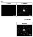
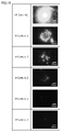
- FIG. FIG. 4 shows images of a detection kit with/without laser light irradiation with a wavelength of 1064 nm and extraction results of regions where bacteria are accumulated.
- FIG. 10 is a diagram showing the results of accumulation of bacteria in samples with different concentrations of bacteria;
- FIG. 16 is a diagram showing the correlation between the concentration of bacteria and the fluorescence area (accumulated area of bacteria) determined from the image shown in FIG. 15;
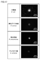
- FIG. 10 is a diagram showing accumulation results of various types of bacteria;
- FIG. 18 is a diagram showing the calculation results of the fluorescence area for each type of bacteria obtained from the image shown in FIG. 17;
- FIG. 10 is a diagram showing the accumulation results of bacteria in a mixed bacterial sample containing two types of bacteria;
- FIG. 1 is an overall configuration diagram of a bacteria detection system according to Embodiment 2.
- FIG. 10 is a flow chart showing a processing procedure of a bacteria detection method according to Embodiment 2.
- FIG. 11 is an overall configuration diagram of a bacteria detection system according to Embodiment 3;
- FIG. 12 is a diagram for explaining in detail the configuration of the detection kit according to Embodiment 3;
- 10 is a flow chart showing a processing procedure of a bacteria detection method according to Embodiment 3.
- sample means a substance containing a substance to be detected or a substance that may contain a substance to be detected.
- a sample can be, for example, a biological sample from an animal (eg, human, cow, horse, pig, goat, chicken, rat, mouse, etc.).
- Biological samples can include, for example, blood, tissue, cells, secretions, bodily fluids, and the like.
- a “sample” may include dilutions thereof.
- the sample may also be a food-derived substance.
- “substance to be detected” means a substance that has a size ranging from nanometer order to micrometer order and is detected using a detection kit.
- the shape of the substance to be detected is not particularly limited, and may be, for example, spherical, elliptical, or rod-like.
- the substance to be detected is an elliptical sphere, at least one of the major axis length and the minor axis length of the elliptical sphere may be in the range of nanometer order to micrometer order.
- the substance to be detected is rod-shaped, at least one of the width and length of the rod should be within the range from the order of nanometers to the order of micrometers.
- substances to be detected include cells, microorganisms (bacteria, fungi, etc.), low molecules (molecules with a molecular weight of about several hundred), medium molecules (molecules with a molecular weight of about 500 to 2000), biopolymers (proteins, nucleic acids , lipids, polysaccharides, etc.), antibodies, antigens (allergens, etc.) and viruses.
- the substances to be detected are not limited to biological substances (biological substances), and include metal nanoparticles, metal nanoparticle aggregates, metal nanoparticle assembly structures, semiconductor nanoparticles, organic nanoparticles, resin beads, and microparticles. and so on.
- a “metal nanoparticle” is a metal particle having a size on the order of nanometers.
- a “metal nanoparticle aggregate” is an aggregate formed by aggregation of a plurality of metal nanoparticles.
- a “metal nanoparticle assembly structure” is, for example, a structure in which a plurality of metal nanoparticles are fixed to the surface of a bead via an interaction site, are spaced apart from each other, and are arranged at intervals equal to or less than the diameter of the metal nanoparticles. is the body.
- a “semiconductor nanoparticle” is a semiconductor particle having a size on the order of nanometers.
- An “organic nanoparticle” is a particle made of an organic compound and having a size on the order of nanometers.
- a “resin bead” is a resin particle having a size ranging from nanometer order to micrometer order.
- Microparticles are particles having a size on the order of micrometers, and include, for example, metal microparticles, semiconductor microparticles, and resin microbeads. Harmful particulates such as PM2.5 and microplastics can also be included in microparticles.
- host substance means a substance capable of specifically binding a substance to be detected.
- Combinations of a host substance and a substance to be detected that can specifically bind the substance to be detected include, for example, an antigen and an antibody, a sugar chain and a protein, a lipid and a protein, a low-molecular-weight compound (ligand) and a protein, and a protein and proteins, single-stranded DNA and single-stranded DNA, proteins and nucleic acid molecules (aptamers), and the like.
- ligand low-molecular-weight compound
- aptamers proteins and nucleic acid molecules
- an antigen can be used as the host substance.
- the substance to be detected is the target DNA and the host substance is the probe DNA.
- Antigens may include allergens, microorganisms (bacteria, fungi, etc.), viruses, and the like. Also, by changing the type of antibody, it is possible to change the type of detectable allergen or virus. Therefore, the types of allergens or viruses detectable by the present disclosure are not particularly limited.
- the substance to be detected is a heavy metal
- a substance capable of capturing heavy metal ions can be used as the host substance.
- the term "microscopic object” means an object having a size ranging from the order of nanometers to the order of micrometers. Similar to the substance to be detected, the shape of the minute object is not particularly limited, and may be, for example, spherical, elliptical, or rod-like. When the minute object is an elliptical sphere, at least one of the major axis length and the minor axis length of the elliptical sphere may be in the range from the order of nanometers to the order of micrometers. When the minute objects are rod-shaped, at least one of the width and the length of the rod should be within the range from the order of nanometers to the order of micrometers.
- the term "absorb light” means the property that the intensity of light absorbed by a substance is greater than zero.
- the wavelength region of light is any region of the ultraviolet region, the visible region, and the near-infrared region, the region spanning two of these three regions, and the region spanning all three regions good.
- Light absorbency can be defined, for example, by a range of light absorption rates. In this case, the lower limit of the range of absorptivity is not particularly limited as long as it is greater than zero. The upper limit of the absorption range is 100%.
- a "honeycomb shape” is a shape in which a plurality of regular hexagons are arranged in a two-dimensional direction in a hexagonal lattice shape (honeycomb shape). Pores are formed in each of the plurality of regular hexagons.
- a structure in which a plurality of pores are arranged in a honeycomb shape is called a "honeycomb structure".
- Each pore is a pore having an opening ranging from the order of nanometers to the order of micrometers.
- the pores may be through holes or non-through holes.
- the shape of the pores is not particularly limited, and may include any shape such as a cylindrical shape, a prismatic shape, or a spherical shape other than a perfect sphere (for example, a hemispherical shape or a semi-elliptical shape).
- microbubbles are micrometer-order bubbles.
- the visible range means a wavelength range of 360 nm to 760 nm.
- the near-infrared region means a wavelength region from 760 nm to 2 ⁇ m.
- the x and y directions represent horizontal directions.
- the x-direction and the y-direction are orthogonal to each other.
- the z direction represents the vertical direction.
- the direction of gravity is downward in the z-direction.
- the upper direction in the z direction may be abbreviated as “upper” and the lower direction in the z direction may be abbreviated as “lower”.
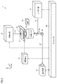
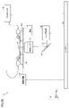
- FIG. 1 is an overall configuration diagram of a bacteria detection system 1 according to Embodiment 1.
- the detection system 1 includes a detection kit 10, an XYZ axis stage 20, a magnet 30, an adjustment mechanism 40, a laser light source 50, an optical component 60, an objective lens 70, an illumination light source 80, an imaging device 91, and a controller 100 .
- the detection kit 10 holds the dropped sample (indicated by SP).
- the sample is a liquid sample that may contain target bacteria.
- the detection kit 10 is installed on the XYZ axis stage 20 . A detailed configuration of the detection kit 10 will be described with reference to FIGS. 2 to 5. FIG.
- the XYZ-axis stage 20 is configured to be movable in the x-, y-, and z-directions by means of an adjustment mechanism 40.
- the adjustment mechanism 40 adjusts the position of the XYZ-axis stage 20 in the x-, y-, and z-directions according to commands from the controller 100 . Since the position of the objective lens 70 is fixed in this embodiment, the relative positional relationship between the detection kit 10 and the objective lens 70 is adjusted by adjusting the position of the XYZ axis stage 20 .
- a driving mechanism such as a servomotor and a focusing handle attached to the microscope can be used, but the specific configuration of the adjustment mechanism 40 is not particularly limited. Note that the adjustment mechanism 40 may be configured to adjust the position of the objective lens 70 with respect to the fixed detection kit 10 .
- the laser light source 50 emits continuous wave (CW) laser light (indicated by L1) according to a command from the controller 100 .
- the wavelength of the laser light is a wavelength included in the absorption wavelength range of the thin film 13 (see FIGS. 2 and 5), for example, a wavelength in the near-infrared range (eg, 800 nm, 1064 nm).
- the wavelength of the laser light may be a wavelength included in the visible range.
- the optical component 60 includes, for example, mirrors, dichroic mirrors, and prisms.
- the optics of the detection system 1 are adjusted such that the laser light from the laser source 50 is guided by the optics 60 to the objective lens 70 .
- the objective lens 70 collects laser light from the laser light source 50 .
- the detection kit 10 is irradiated with the light condensed by the objective lens 70 .
- “irradiate” includes the case where the laser light passes through the detection kit 10 . That is, it is not limited to the case where the beam waist of the light condensed by the objective lens 70 is positioned within the detection kit 10 .
- the optical component 60 and the objective lens 70 can be incorporated into, for example, an inverted microscope main body or an upright microscope main body. In this example, the objective lens 70 is built into the body of the inverted microscope and its magnification is 40x (dry).
- the illumination light source 80 emits white light (indicated by L2) for illuminating the sample on the detection kit 10 according to instructions from the controller 100 .
- a halogen lamp can be used as illumination source 80 .
- Objective lens 70 is also used to capture the white light emitted from illumination source 80 onto detection kit 10 .
- White light captured by the objective lens 70 is guided by the optical component 60 to the imaging device 91 .
- the photographing device 91 photographs the sample on the detection kit 10 irradiated with white light according to a command from the controller 100 and outputs the photographed image to the controller 100 .
- An image captured by the imaging device 91 may be a still image or a moving image.
- a camera including a CCD (Charge Coupled Device) image sensor or a CMOS (Complementary Metal Oxide Semiconductor) image sensor can be used as the imaging device 91 .
- the imaging device 91 is an example of the “light receiver” and the “detector” according to the present disclosure.
- the controller 100 includes a processor such as a CPU (Central Processing Unit), memories such as ROM (Read Only Memory) and RAM (Random Access Memory), and input/output ports through which various signals are obtained. include.
- the controller 100 controls each device in the detection system 100 (the adjustment mechanism 40, the laser light source 50, the illumination light source 80 and the imaging device 91). Also, the controller 100 detects target bacteria in the sample by performing predetermined image processing on the image captured by the imaging device 91 .
- FIG. 2 is a conceptual diagram for explaining the configuration of the detection kit 10.
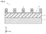
- FIG. 3 is a cross-sectional view of detection kit 10 along line III-III of FIG.
- a detection kit 10 includes a substrate 11 , a honeycomb polymer membrane 12 and a thin film 13 .
- the substrate 11 gives the detection kit 10 mechanical strength.
- a material transparent to the laser light is used as the material of the substrate 11 .
- glass can be used.
- the honeycomb polymer membrane 12 is arranged on the substrate 11 .
- the honeycomb polymer membrane 12 is a polymer membrane having a plurality of pores 14 arranged in a honeycomb shape along its surface. Each pore 14 may be a non-through pore or a through pore communicating with an adjacent pore.
- a resin for example, polystyrene
- Patent Document 1 can be referred to for a method of manufacturing a honeycomb polymer membrane.
- the thin film 13 is arranged on the honeycomb polymer membrane 12 .
- the thin film 13 may be partially formed in the region irradiated with the laser beam (the position of the laser spot), the thin film 13 is formed so as to cover the entire surface of the honeycomb polymer film 12 in the first embodiment. ing.
- the film thickness of the thin film 13 is on the order of nanometers. Therefore, the thin film 13 has a honeycomb structure reflecting the structure of the honeycomb polymer film 12 .
- the thin film 13 absorbs laser light from the laser light source 50 and converts light energy into heat energy.
- the material of the thin film 13 is preferably a material having high light absorption (for example, photothermal conversion efficiency) in the wavelength range of laser light (near-infrared range in this embodiment).
- a gold thin film is formed as the thin film 13 . Free electrons on the gold thin film surface form surface plasmons and oscillate with laser light. This causes polarization. This polarization energy is converted into lattice vibrational energy by the Coulomb interaction between the free electrons and the nucleus. As a result, the gold film generates heat. In the following, this effect is also referred to as "photoheating effect".
- the material of the thin film 13 is not limited to gold, and metal elements other than gold (for example, silver and platinum) or metal nanoparticle assembly structures (for example, gold nanoparticles or silver nanoparticles) capable of producing a photo-heating effect may be used. structure used).
- the material of the thin film 13 may be a material other than metal that has high light absorption in the wavelength range of laser light. Such materials include materials close to black bodies (for example, carbon nanotube black bodies).
- the honeycomb polymer film 12 and thin film 13 correspond to the "photothermal conversion region" according to the present disclosure.
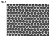
- FIG. 4 is a diagram showing a top surface SEM (Scanning Electron Microscope) image of the honeycomb polymer membrane 12 produced in this embodiment.
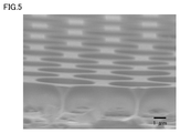
- FIG. 5 is a view showing a perspective SEM image of the honeycomb polymer membrane 12 produced in this embodiment.
- the diameter (pore diameter) of the pores 14 was 4 to 5 ⁇ m.
- the depth of the pores 14 was approximately 3 ⁇ m.
- the sample contains a plurality of minute objects for detecting target bacteria.
- FIG. 6 is a diagram showing a minute object in this embodiment.
- the micro-object includes magnetic beads 21 .
- the magnetic bead 21 has a macromolecular polymer core 211 , a magnetite layer 212 covering the core 211 , and a protective layer (for example, a hydrophilic polymer layer) 213 covering the magnetite layer 212 .
- Each layer of the magnetite layer 212 and the protective layer 213 may be two or more layers.
- Thermo Scientific Pierce Protein A/G magnetic beads (particle diameter 1 ⁇ m) manufactured by Thermo Fisher Scientific can be used.
- the magnetite layer 212 contains a magnetic material ( ⁇ Fe 2 O 3 and Fe 3 O 4 etc.). Magnetic beads 21 exhibit paramagnetism. Therefore, the magnetic beads 21 are dispersed in the sample when no external magnetic field is applied.
- the surface of the magnetic beads 21 is modified with a host substance.
- the host material is an antibody 22 capable of specifically binding to the target bacteria.
- Various types of antibodies can be modified on the surface of magnetic beads by known techniques.
- the magnetic beads 21 modified with the antibodies 22 are hereinafter also referred to as "antibody-modified beads 23". Note that the antibody-modified beads 23 are an example of "magnetic particles" according to the present disclosure.
- FIG. 7 is a conceptual diagram showing how the antibody-modified beads 23 are introduced into the plurality of pores 14 arranged in the honeycomb polymer membrane 12. As shown in FIG. As shown in FIG. 7 , when the magnet 30 is placed below the detection kit 10 , the antibody-modified beads 23 are attracted downward by the magnetic field of the magnet 30 and introduced into the pores 14 .
- FIG. 8 is a diagram showing an optical transmission image of the upper surface of the detection kit 10 into which the antibody-modified beads 23 have been introduced.
- FIG. 9 is an enlarged view of the optical transmission image shown in FIG. An objective lens 70 with a magnification of 100 was used for this measurement.
- the diameter of the antibody-modified beads 23 was 1 ⁇ m. In other words, the antibody-modified beads 23 are smaller than the pore size (4-5 ⁇ m). In this example, it was confirmed that about two or three antibody-modified beads 23 were captured inside each pore 14 . By capturing the antibody-modified beads 23 inside the pores 14 in this way, the antibody-modified beads 23 can be stably held on the detection kit 10 .
- the antibody-modified beads 23 are captured.
- the antibody-modified beads 23 are larger than the pore diameter, the antibody-modified beads 23 can be collected while riding on the openings of the pores 14 .
- the stability is not as good as when the antibody-modified beads 23 are trapped inside the pores 14, such a trapping mode can also be adopted.
- the antibody-modified beads 23 can also be introduced into the pores 14 by natural sedimentation or pipetting, although this may be more time-consuming than techniques using an external magnetic field, ultrasonic waves, or thermal convection. This is because the specific gravity of the antibody-modified beads 23 is higher than the specific gravity of the sample dispersion medium (typically water).
- sample dispersion medium typically water.
- FIG. 10 is a conceptual diagram for explaining how bacteria (indicated by B) are accumulated using the detection kit 10 .
- the vicinity of the laser spot is locally heated due to the photo-heating effect of the thin film 13 in the region irradiated with the laser light (hereinafter also referred to as “laser spot”).
- the dispersion medium in this example, water
- the sample near the laser spot boils to generate microbubbles (indicated by MB) in the laser spot. Microbubbles grow over time.
- thermal convection is constantly generated in the dispersion medium in addition to microbubbles.
- the direction of heat convection is, as indicated by arrows, once toward the microbubbles and then away from the microbubbles.
- Thermal convection is classified into buoyant convection and Marangoni convection.
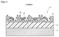
- FIG. 11 is a diagram for explaining the accumulation of bacteria in a comparative example.
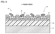
- 12A and 12B are diagrams for explaining an accumulation mode of bacteria in the present embodiment.
- FIG. 11 is a diagram for explaining the accumulation of bacteria in a comparative example.
- 12A and 12B are diagrams for explaining an accumulation mode of bacteria in the present embodiment.
- FIG. 11 is a diagram for explaining the accumulation of bacteria in a comparative example.
- 12A and 12B are diagrams for explaining an accumulation mode of bacteria in the present embodiment.
- antibody-modified beads 23 with magnetic beads 21 as cores are interposed between bacteria and thin film 13 .
- the thermal conductivity of magnetic beads 21 is significantly lower than that of thin film 13 .
- the thermal conductivity of gold which is a representative material of the thin film 13
- the polymer for example, The thermal conductivity of polystyrene is about 0.1 [W/(m ⁇ K)].
- partition walls are formed between the adjacent pores 14 of the thin film 13 . It is desirable to adjust the optical system of the detection system 2 so that the partition walls (especially the upper surfaces of the partition walls) are irradiated with laser light. Since the partition wall protrudes into the liquid, the heat generated on the upper surface of the partition wall intensively heats the liquid in the vicinity of the upper surface of the partition wall. Then, since the laser spot acts as a so-called "point heat source", the range in which excessive temperature rise occurs around the laser spot is narrowed.
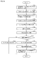
- FIG. 13 is a flow chart showing a processing procedure of a bacteria detection method according to Embodiment 1.
- FIG. Flowcharts shown in FIG. 13 and later-described FIGS. 28 and 31 are executed when predetermined conditions are established (for example, when the measurer operates a measurement start button (not shown)).
- Each step is basically realized by software processing by the controller 100 , but may be realized by hardware (electric circuit) arranged in the controller 100 .
- a step is abbreviated as S below.
- a sample in which a plurality of antibody-modified beads 23 are dispersed is prepared and dropped onto the detection kit 10.
- the amount of sample to be dropped may be as small as several microliters to several hundreds of microliters, or may be larger. This process may be performed by the measurer, but can also be automated using a dispenser (not shown).
- the detection kit 10 is installed on the XYZ axis stage 20. This process may also be performed by the subject, but can be automated by a mechanism (not shown) that delivers the detection kit 10, for example.
- the horizontal (x-direction, y-direction) and vertical (z-direction) positions of the XYZ-axis stage 20 are adjusted so that the sample is irradiated with the laser light from the laser light source 50 .
- This process may be realized by manual operation of the adjustment mechanism 40 by the measurer. Alternatively, this process may be implemented by controller 100 controlling adjustment mechanism 40 .
- the horizontal position adjustment can be realized, for example, by extracting the outline of the sample from the image photographed by the photographing device 91 using pattern recognition image processing technology.
- the vertical position of the beam waist of the laser light is known from the wavelength of the laser light and the specifications (magnification, etc.) of the objective lens 70 . Therefore, by adjusting the position of the XYZ-axis stage 20 in the vertical direction, the beam waist can be set at a target height.
- the controller 100 controls the laser light source 50 to irradiate the sample with laser light for a predetermined time.
- the output of the laser light (laser output) and the irradiation time (laser irradiation time) are, for example, depending on the specifications of the detection kit 10 (material of the thin film 13, film thickness, etc.) and the characteristics of bacteria (assumed concentration, size, etc.). Determined based on the results of prior experiments or simulations. It is desirable to set the laser power and laser irradiation time to be large/long enough to generate microbubbles and convection in the sample, and to be small/short enough not to cause excessive thermal damage to the bacteria.
- the laser output is several mW to several tens of mW
- the laser irradiation time is several tens of seconds to several minutes.
- Bacteria are accumulated in the laser spot according to the mechanism described with reference to FIG. 10 by laser light irradiation.
- the detection kit 10 is washed by the measurer. This leaves the target bacteria that are specifically bound to the antibody-modified beads in the detection kit 10, while the others are washed away.
- the detection kit 10 after cleaning is placed on the XYZ-axis stage 20 again.
- the controller 100 controls the illumination light source 80 to emit white light for illuminating the detection kit 10 and controls the photographing device 91 to photograph the detection kit 10 .
- the controller 100 determines whether an aggregate of bacteria is observed in the image captured by the imaging device 91. If no accumulation of bacteria was observed (NO in S107), the controller 100 determines that the sample does not contain the target bacteria (the concentration of bacteria in the sample is below the detection limit) (S109). ).
- the controller 100 determines that the sample contains target bacteria (S110). In this case, the controller 100 calculates the area of the area where the bacteria are accumulated (accumulated area) (S111). For example, the controller 100 can calculate the area of an area where bacteria are accumulated by extracting the area using pattern recognition image processing technology. Furthermore, the controller 100 calculates the concentration of bacteria contained in the sample (bacteria concentration) from the accumulation area calculated in S111 by referring to a previously determined calibration curve (see FIG. 16) (S112 ). After completing the process of S109 or S112, the controller 100 returns the process to the main routine.
- FIG. 15 is a diagram showing the accumulation results of bacteria in samples having different concentrations of bacteria.
- Escherichia coli was used as the target bacterium.
- Six samples with different bacterial concentrations ranging from 10 3 [cells/mL] to 10 8 [cells/mL] were prepared.
- the bacteria were fluorescently stained and the fluorescent images were taken.
- the laser output was set to 20 mW, and the laser irradiation time was set to 7 minutes. Fluorescence (that is, accumulation of bacteria) was confirmed even in the sample with the lowest bacterial concentration of 10 3 [cells/mL].
- FIG. 16 is a diagram showing the correlation between the bacterial concentration and fluorescence area obtained from the image shown in FIG.
- the horizontal axis represents the bacterial concentration on a logarithmic scale.
- the vertical axis represents the fluorescence area (accumulated area of bacteria) on a logarithmic scale. Three measurements were taken at each bacterial concentration. The same applies to FIG. 24 (described later).
- the correlation between bacterial concentration and fluorescence area was represented linearly on a log-log graph. By obtaining such a correlation in advance and using it as a calibration curve, it becomes possible to calculate the bacterial concentration from the fluorescence area (see S112 in FIG. 13).
- FIG. 18 is a diagram showing the calculation results of the fluorescence area (accumulated area) for each type of bacteria obtained from the image shown in FIG. Error bars represent standard deviation in triplicate determinations.
- the accumulated area of E. coli was about 5 to 15 times larger than that of the other three types of bacteria. Thus, it can be said that the selective detection (specific detection) of E. coli was successful because there was a remarkable difference in the accumulated area and the E. coli could be clearly distinguished from other bacteria.
- FIG. 19 is a diagram showing the results of bacterial accumulation in a mixed bacterial sample containing two types of bacteria.
- a mixed bacterial sample containing E. coli and Staphylococcus aureus was used in this assay. Both E. coli and Staphylococcus aureus were fluorescently stained.
- the total concentration of the two types of bacteria in each sample was 10 8 [cells/mL].
- the laser output (output before passing through the objective lens) was set to 20 mW, and the laser irradiation time was set to 7 minutes.
- Antibody 22 that specifically binds to E. coli was used for antibody-modified beads 23 . These conditions are also common to FIGS. 21 and 22 described later. As shown in FIG. 19, it was observed that the higher the E. coli ratio, the larger the fluorescence area.
- FIG. 20 is a diagram showing the calculation result of the fluorescence area obtained from the image shown in FIG.
- the horizontal axis represents the ratio of E. coli.
- FIG. 20 it was confirmed that the fluorescent area increased monotonously as the proportion of E. coli increased. From this, it can be said that E. coli was successfully selectively detected in a mixed bacterial sample containing two types of bacteria.
- FIG. 21 is a diagram showing the results of bacterial accumulation in a mixed bacterial sample containing four types of bacteria.
- This assay used a mixed bacterial sample containing E. coli, Staphylococcus aureus, Klebsiella pneumoniae and Salmonella. All bacteria E. coli, Staphylococcus aureus, Klebsiella pneumoniae and Salmonella were fluorescently stained. Eight types of samples with different E. coli ratios ranging from 0% to 100% were prepared. The total concentration of the four types of bacteria in each sample was 10 8 [cells/mL]. Also in this measurement, it was observed that the higher the E. coli ratio, the larger the fluorescence area.
- FIG. 22 is a diagram showing the calculation result of the fluorescence area obtained from the image shown in FIG. It was confirmed that the fluorescent area increased monotonically as the proportion of E. coli increased. Thus, E. coli was successfully selectively detected even in a mixed bacterial sample containing four types of bacteria.
- FIG. 23 shows the results of bacterial accumulation in contaminant samples.
- a contaminant sample is a sample that contains, in addition to the substance to be detected, substances other than the substance to be detected as contaminants.
- a contaminant sample containing E. coli in apple juice was used for this measurement. More specifically, the following concentration series of bacteria was added (standard addition) to apple juice, and allowed to stand for 10 minutes. After further centrifugation, the bacteria were redispersed in phosphate buffer. Similar to FIGS. 15 and 16, six samples with different bacterial concentrations ranging from 10 3 [cells/mL] to 10 8 [cells/mL] were prepared. Also in this example, the bacteria were fluorescently stained and the fluorescent images were taken. The laser output was set to 20 mW, and the laser irradiation time was set to 7 minutes. Even in apple juice containing contaminants, fluorescence was confirmed in the sample with the lowest bacterial concentration of 10 3 [cells/mL].
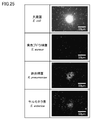
- FIG. 25 shows the accumulation results of various types of bacteria in contaminant samples.
- Four types of samples were prepared in the same manner as in FIG. Each sample contains any one of four types of bacteria (E. coli, Staphylococcus aureus, Klebsiella pneumoniae and Salmonella). Each bacterium was fluorescently stained. Antibody 22 that specifically binds to E. coli was used for antibody-modified beads 23 . The bacterial concentration in each sample was 10 8 [cells/mL]. The laser output was set to 20 mW, and the laser irradiation time was set to 7 minutes. Fluorescence was observed in all four samples, but the fluorescence was most pronounced in the sample containing E. coli.
- FIG. 26 is a diagram showing the calculation results of the fluorescence area for each type of bacteria obtained from the image shown in FIG. Error bars represent standard deviation in triplicate measurements.
- the fluorescence area of E. coli was 8 to 15 times larger than that of the other three bacteria.
- Embodiment 2 In Embodiment 2, a configuration for detecting target bacteria based on the spectrum of the detection kit 10 will be described.
- FIG. 27 is an overall configuration diagram of the bacteria detection system 2 according to the second embodiment.
- the detection system 2 differs from the detection system 1 according to Embodiment 1 (see FIG. 1) in that it includes a spectrophotometer 92 instead of the imaging device 91 .
- the spectrophotometer 92 measures the reflection spectrum of the detection kit 10 according to instructions from the controller 100 and outputs the measurement results to the controller 100 .
- Spectrophotometer 92 includes, for example, a diffraction grating, a light receiving element, a shutter, and a slit (all not shown).
- Light incident on the spectrophotometer 92 reaches the diffraction grating after passing through the slit.
- incident light is reflected in a direction according to its wavelength.
- the surface of the light receiving element is divided into a plurality of unit areas.
- the light reflected by the diffraction grating is incident on a unit area corresponding to the wavelength among the plurality of unit areas of the light receiving element.
- the configuration of the detection system 2 other than the spectrophotometer 92 is the same as the corresponding configuration of the detection system 1, so the description will not be repeated.
- FIG. 27 shows an optical system for measuring the transmission spectrum of the detection kit 10, the detection system 2 is configured to measure other spectra (reflection spectrum, scattering spectrum, etc.). may
- FIG. 28 is a flow chart showing the processing procedure of the bacteria detection method according to the second embodiment.
- the processing of S201 to S204 is the same as the processing of S101 to S104 in Embodiment 1 (see FIG. 13), respectively.
- the controller 100 controls the illumination light source 80 to emit white light. Then, the controller 100 acquires the transmission spectrum of the area to be irradiated with the laser light from the spectrophotometer 92 prior to irradiation with the laser light.
- the controller 100 controls the laser light source 50 so as to output laser light with a predetermined output for a predetermined period of time. After accumulating the bacteria, the laser light irradiation is stopped. After that, the measurement person cleans the detection kit 10 to wash away bacteria other than the target bacteria (S207). The detection kit 10 after cleaning is placed on the XYZ-axis stage 20 again.
- the controller 100 acquires from the spectrophotometer 92 the transmission spectrum in the area irradiated with the laser light. After obtaining the transmission spectrum, the white light irradiation can be terminated.
- the type of spectrum acquired by the detection system 2 is not particularly limited. Detection system 2 may acquire a reflectance spectrum, an extinction spectrum, or a fluorescence spectrum.
- the controller 100 compares the transmission spectrum acquired in S205 and the transmission spectrum acquired in S208 to determine whether there is a change in the intensity of the transmission spectrum. For example, the controller 100 can determine that there is an intensity change when an intensity change of a predetermined amount or more is detected at a predetermined specific wavelength. If no intensity change in the transmission spectrum is detected (NO in S209), controller 100 determines that the sample does not contain the target bacteria (S210).
- the controller 100 determines that the sample contains the target bacteria (S211). The controller 100 then calculates the concentration of the target bacteria from the amount of change in intensity (S212). As with the calibration curve described with reference to FIG. 16, this process is also realized by obtaining in advance the correlation between the amount of change in intensity at a specific wavelength and the concentration of bacteria. After completing the process of S210 or S212, the controller 100 returns the process to the main routine.
- Embodiment 2 bacteria are accumulated using the detection kit 10 in which the antibody-modified beads 23 are introduced into the pores 14 .
- target bacteria can be accumulated selectively and with high efficiency.
- a spectrum is used instead of the accumulation area of bacteria for detection of target bacteria. Therefore, according to Embodiment 2, it is possible to selectively and rapidly detect a substance to be detected that may be contained in a sample.
- Embodiment 3 In Embodiment 3, a configuration for detecting target bacteria based on the electrical resistance (impedance) of the detection kit will be described.
- FIG. 29 is an overall configuration diagram of the bacteria detection system 3 according to the third embodiment.
- Detection system 3 is similar to detection system 1 according to Embodiment 1 (see FIG. 1) in that detection kit 10A is provided instead of detection kit 10, and multimeter 93 is provided instead of illumination light source 80 and photographing device 91. ) is different.
- the multimeter 93 is an impedance measuring device configured to measure electrical resistance between the electrodes 31 and 32 (see FIG. 30) provided in the detection kit 10A. More specifically, multimeter 93 measures the voltage between electrodes 31 and 32 while passing a constant current between electrodes 31 and 32 according to a command from controller 100 . A measurement result by the multimeter 93 is output to the controller 100 .
- the multimeter 93 is another example of the "detection device" according to the present disclosure.
- the electrodes 31 and 32 correspond to the "first electrode” and the "second electrode” according to the present disclosure.
- FIG. 31 is a flow chart showing the processing procedure of the bacteria detection method according to the third embodiment.
- the processing of S303 to S306 is the same as the processing of S101 to S106 in the first embodiment (see FIG. 13), respectively, so the description will not be repeated.
- the controller 100 acquires from the multimeter 93 the voltage between the electrodes 31 and 32 in the detection kit 10A after washing. The controller 100 then calculates the electrical resistance between the electrodes 31 and 32 .
- the controller 100 determines whether the difference (absolute value) between the electrical resistance calculated in S ⁇ b>307 and the reference value falls within a predetermined measurement range according to the characteristics of the multimeter 93 .
- a reference value is set based on the electrical resistance of a sample (dispersion medium) that does not contain the target bacteria.
- Embodiment 3 bacteria are accumulated using the detection kit 10 in which the antibody-modified beads 23 are introduced into the pores 14 .
- target bacteria can be accumulated selectively and with high efficiency.
- changes in electrical resistivity are used to detect target bacteria. Even in this case, target bacteria can be selectively detected as in the first and second embodiments. Therefore, according to Embodiment 3, it is possible to selectively and rapidly detect a substance to be detected that may be contained in a sample.
- a method for detecting a substance to be detected which detects a substance to be detected that may be contained in a liquid sample using a detection kit
- the detection kit includes a photothermal conversion region that absorbs light and converts it to heat, A plurality of pores are arranged in the photothermal conversion region,
- the detection method is introducing into the plurality of pores a plurality of micro-objects each having a surface modified with a host substance capable of specifically binding to the substance to be detected; a step of heating the liquid sample by irradiating the photothermal conversion region with light having a wavelength included in the absorption wavelength range of the photothermal conversion region to generate thermal convection in the liquid sample; and detecting the substance to be detected by monitoring the detection kit after irradiation with the light.
- Appendix 2 The method for detecting a substance to be detected according to Appendix 1, wherein the size of each of the plurality of minute objects is smaller than the diameter of each of the plurality of pores.
- each of the plurality of micro-objects includes a core;
- the photothermal conversion region includes a thin film that converts the light into heat, 3.
- Appendix 4 The method for detecting a substance to be detected according to any one of Appendices 1 to 3, wherein the plurality of pores are arranged in a honeycomb shape.
- Appendix 7 The method according to any one of Appendices 1 to 4, wherein the introducing step includes introducing the plurality of micro-objects into the plurality of pores by thermal convection generated by irradiating the light to the photothermal conversion region. A method for detecting the described substance to be detected.
- the specific gravity of the plurality of minute objects is greater than the specific gravity of the liquid sample; Detection of the substance to be detected according to any one of Appendices 1 to 4, wherein the step of introducing includes a step of introducing the plurality of micro-objects into the plurality of pores by natural sedimentation of the plurality of micro-objects.
- the light receiver includes a photographing device;
- the step of calculating the concentration of the substance to be detected includes: calculating an accumulated area of the substance to be detected from the image captured by the imaging device; and calculating the concentration of the substance to be detected from the calculated accumulated area by referring to the correlation between the concentration of the substance to be detected and the accumulated area of the substance to be detected.
- a method for detecting a substance to be detected includes: calculating an accumulated area of the substance to be detected from the image captured by the imaging device; and calculating the concentration of the substance to be detected from the calculated accumulated area by referring to the correlation between the concentration of the substance to be detected and the accumulated area of the substance to be detected.
- Appendix 12 The detection target substance according to any one of Appendices 1 to 11, wherein the step of detecting the target substance comprises selectively detecting the target substance from among a plurality of substances including the target substance. Substance detection method.
- the liquid sample is a sample containing contaminants, 13.
- the light receiver includes a spectroscope that measures a spectrum of light from the liquid sample;
- the detection kit further includes first and second electrodes spaced apart from each other to sandwich the photothermal conversion region, Any one of Appendices 1 to 8, wherein detecting the substance to be detected includes detecting the substance to be detected based on a change in electrical resistance between the first electrode and the second electrode. 2. The method for detecting a substance to be detected according to item 1.
- a detection kit for a substance to be detected which is used for detecting a substance to be detected that may be contained in a liquid sample, Equipped with a photothermal conversion region that absorbs light and converts it into heat, A plurality of pores are arranged in the photothermal conversion region, A detection kit for a substance to be detected, further comprising a plurality of microscopic objects each having a surface modified with a host substance capable of specifically binding to the substance to be detected in the plurality of pores.
- a detection system for a substance to be detected comprising: a detection device that detects the substance to be detected by monitoring the detection kit after irradiation with light from the light source.
- Appendix 18 A method for producing a detection kit used for detecting a substance to be detected that may be contained in a liquid sample, preparing the detection kit having a photothermal conversion region in which a plurality of pores are arranged; introducing into the plurality of pores a plurality of microscopic objects each having a surface modified with a host substance capable of specifically binding to the substance to be detected.
- the present disclosure highly efficiently accumulates various substances to be detected dispersed in a liquid sample (for example, harmful fine particles such as PM2.5, environmentally hazardous substances such as microplastics or nanoplastics, or various bacteria or viruses). By doing so, the substance to be detected can be used in a manner of detecting the substance to be detected with high sensitivity and speed. The present disclosure can also be used to determine whether a liquid sample contains minute objects and/or to identify the concentration of minute objects in a liquid sample.
- 1 to 3 detection system 10, 10A detection kit, 11 substrate, 12 honeycomb polymer membrane, 13 thin film, 14 pores, 20 XYZ axis stage, 21 magnetic beads, 211 core, 212 magnetite layer, 213 protective layer, 22 antibody , 23 antibody-modified beads, 30 magnets, 31, 32 electrodes, 40 adjustment mechanism, 50 laser light source, 60 optical components, 70 objective lens, 80 illumination light source, 91 imaging equipment, 92 spectrophotometer, 93 multimeter, 100 controller.
Landscapes
- Chemical & Material Sciences (AREA)
- Health & Medical Sciences (AREA)
- Analytical Chemistry (AREA)
- General Health & Medical Sciences (AREA)
- Immunology (AREA)
- General Physics & Mathematics (AREA)
- Pathology (AREA)
- Dispersion Chemistry (AREA)
- Physics & Mathematics (AREA)
- Life Sciences & Earth Sciences (AREA)
- Biochemistry (AREA)
- Clinical Laboratory Science (AREA)
- Hematology (AREA)
- Chemical Kinetics & Catalysis (AREA)
- Apparatus Associated With Microorganisms And Enzymes (AREA)
- Investigating, Analyzing Materials By Fluorescence Or Luminescence (AREA)
- Investigating Or Analysing Materials By Optical Means (AREA)
- Investigating Or Analyzing Materials By The Use Of Electric Means (AREA)
Priority Applications (3)
| Application Number | Priority Date | Filing Date | Title |
|---|---|---|---|
| US18/289,837 US20240241026A1 (en) | 2021-05-07 | 2022-05-02 | Method for Detecting Analyte, Detection Kit and Detection System, and Method for Manufacturing Detection Kit |
| EP22798953.0A EP4336169A4 (en) | 2021-05-07 | 2022-05-02 | METHOD FOR DETECTING A SUBSTANCE TO BE DETECTED, DETECTION KIT AND DETECTION SYSTEM, AND METHOD FOR MANUFACTURING A DETECTION KIT |
| JP2023518698A JP7515940B2 (ja) | 2021-05-07 | 2022-05-02 | 被検出物質の検出方法、検出キットおよび検出システム、ならびに、検出キットの製造方法 |
Applications Claiming Priority (2)
| Application Number | Priority Date | Filing Date | Title |
|---|---|---|---|
| JP2021-079295 | 2021-05-07 | ||
| JP2021079295 | 2021-05-07 |
Publications (1)
| Publication Number | Publication Date |
|---|---|
| WO2022234849A1 true WO2022234849A1 (ja) | 2022-11-10 |
Family
ID=83932745
Family Applications (1)
| Application Number | Title | Priority Date | Filing Date |
|---|---|---|---|
| PCT/JP2022/019532 Ceased WO2022234849A1 (ja) | 2021-05-07 | 2022-05-02 | 被検出物質の検出方法、検出キットおよび検出システム、ならびに、検出キットの製造方法 |
Country Status (4)
| Country | Link |
|---|---|
| US (1) | US20240241026A1 (https=) |
| EP (1) | EP4336169A4 (https=) |
| JP (1) | JP7515940B2 (https=) |
| WO (1) | WO2022234849A1 (https=) |
Families Citing this family (1)
| Publication number | Priority date | Publication date | Assignee | Title |
|---|---|---|---|---|
| US12246322B2 (en) * | 2019-04-25 | 2025-03-11 | University Public Corporation Osaka | Microscopic object collection method and microscopic object collection system |
Citations (11)
| Publication number | Priority date | Publication date | Assignee | Title |
|---|---|---|---|---|
| JP2005283556A (ja) * | 2004-03-05 | 2005-10-13 | Canon Inc | 標的物質認識素子、検出方法及び装置 |
| WO2012077756A1 (ja) * | 2010-12-08 | 2012-06-14 | 公立大学法人大阪府立大学 | 金属ナノ粒子集積構造体を利用した被検出物質の検出装置および方法 |
| US20140293731A1 (en) * | 2013-03-27 | 2014-10-02 | Nanotemper Technologies Gmbh | Method and apparatus for contactless mixing of liquids |
| WO2014192937A1 (ja) * | 2013-05-30 | 2014-12-04 | 公立大学法人大阪府立大学 | 被検出物質の検出装置および方法 |
| US20150316480A1 (en) * | 2014-05-05 | 2015-11-05 | Nanotemper Technologies Gmbh | Thermophoresis measurements in nanoliterdroplets |
| WO2017090087A1 (ja) * | 2015-11-24 | 2017-06-01 | 株式会社日立ハイテクノロジーズ | 生体試料分析装置および生体試料分析方法 |
| JP2017202446A (ja) | 2016-05-11 | 2017-11-16 | 公立大学法人大阪府立大学 | 微小物体の捕集装置および捕集キットならびに微小物体の捕集方法 |
| WO2018159706A1 (ja) * | 2017-02-28 | 2018-09-07 | 公立大学法人大阪府立大学 | 微小物体の集積装置、および、それに用いられる集積容器ならびに微小物体の集積方法 |
| WO2018207937A1 (ja) * | 2017-05-12 | 2018-11-15 | 公立大学法人大阪府立大学 | インピーダンス測定システムおよびインピーダンス測定方法ならびに被検出物質の検出システム |
| JP2018194550A (ja) * | 2017-05-12 | 2018-12-06 | 公立大学法人大阪府立大学 | 被検出物質の検出キットおよびそれを備えた検出システム、ならびに、被検出物質の検出キットの製造方法 |
| WO2020218347A1 (ja) * | 2019-04-25 | 2020-10-29 | 公立大学法人大阪 | 微小物体の集積方法および微小物体の集積システム |
Family Cites Families (1)
| Publication number | Priority date | Publication date | Assignee | Title |
|---|---|---|---|---|
| WO2017127570A1 (en) * | 2016-01-20 | 2017-07-27 | Triv Tech, Llc | Point-of-care nucleic acid amplification and detection |
-
2022
- 2022-05-02 WO PCT/JP2022/019532 patent/WO2022234849A1/ja not_active Ceased
- 2022-05-02 EP EP22798953.0A patent/EP4336169A4/en active Pending
- 2022-05-02 JP JP2023518698A patent/JP7515940B2/ja active Active
- 2022-05-02 US US18/289,837 patent/US20240241026A1/en active Pending
Patent Citations (12)
| Publication number | Priority date | Publication date | Assignee | Title |
|---|---|---|---|---|
| JP2005283556A (ja) * | 2004-03-05 | 2005-10-13 | Canon Inc | 標的物質認識素子、検出方法及び装置 |
| WO2012077756A1 (ja) * | 2010-12-08 | 2012-06-14 | 公立大学法人大阪府立大学 | 金属ナノ粒子集積構造体を利用した被検出物質の検出装置および方法 |
| US20140293731A1 (en) * | 2013-03-27 | 2014-10-02 | Nanotemper Technologies Gmbh | Method and apparatus for contactless mixing of liquids |
| WO2014192937A1 (ja) * | 2013-05-30 | 2014-12-04 | 公立大学法人大阪府立大学 | 被検出物質の検出装置および方法 |
| US20150316480A1 (en) * | 2014-05-05 | 2015-11-05 | Nanotemper Technologies Gmbh | Thermophoresis measurements in nanoliterdroplets |
| WO2017090087A1 (ja) * | 2015-11-24 | 2017-06-01 | 株式会社日立ハイテクノロジーズ | 生体試料分析装置および生体試料分析方法 |
| JP2017202446A (ja) | 2016-05-11 | 2017-11-16 | 公立大学法人大阪府立大学 | 微小物体の捕集装置および捕集キットならびに微小物体の捕集方法 |
| JP6375578B2 (ja) | 2016-05-11 | 2018-08-22 | 公立大学法人大阪府立大学 | 微小物体の捕集装置および捕集キットならびに微小物体の捕集方法 |
| WO2018159706A1 (ja) * | 2017-02-28 | 2018-09-07 | 公立大学法人大阪府立大学 | 微小物体の集積装置、および、それに用いられる集積容器ならびに微小物体の集積方法 |
| WO2018207937A1 (ja) * | 2017-05-12 | 2018-11-15 | 公立大学法人大阪府立大学 | インピーダンス測定システムおよびインピーダンス測定方法ならびに被検出物質の検出システム |
| JP2018194550A (ja) * | 2017-05-12 | 2018-12-06 | 公立大学法人大阪府立大学 | 被検出物質の検出キットおよびそれを備えた検出システム、ならびに、被検出物質の検出キットの製造方法 |
| WO2020218347A1 (ja) * | 2019-04-25 | 2020-10-29 | 公立大学法人大阪 | 微小物体の集積方法および微小物体の集積システム |
Non-Patent Citations (3)
| Title |
|---|
| HAYASHI KOTA, YAMAMOTO YASUYUKI, TAMURA MAMORU, TOKONAMI SHIHO, IIDA TAKUYA: "Damage-free light-induced assembly of intestinal bacteria with a bubble-mimetic substrate", COMMUNICATIONS BIOLOGY, vol. 4, no. 1, 1 December 2021 (2021-12-01), pages 1 - 7, XP093000341, DOI: 10.1038/s42003-021-01807-w * |
| MASATOSHI KANODA; KOTA HAYASHI; MAMORU TAMURA; SHIHO TOKONAMI; TAKUYA IIDA: "12p-N107-11 Detection of Nanoparticles by Optical Condensation with Plasmonic Nano-bowl Substrate", PROCEEDINGS OF THE 82ND JSAP AUTUMN MEETING, JAPAN SOCIETY OF APPLIED PHYSICS; [ONLINE VIRTUAL MEETING]; SEPTEMBER 22-23, 2021, vol. 82, 28 February 2020 (2020-02-28) - 23 September 2021 (2021-09-23), pages 1 - 1, XP009540792 * |
| See also references of EP4336169A4 |
Also Published As
| Publication number | Publication date |
|---|---|
| EP4336169A1 (en) | 2024-03-13 |
| EP4336169A4 (en) | 2025-05-21 |
| US20240241026A1 (en) | 2024-07-18 |
| JPWO2022234849A1 (https=) | 2022-11-10 |
| JP7515940B2 (ja) | 2024-07-16 |
Similar Documents
| Publication | Publication Date | Title |
|---|---|---|
| JP6379149B2 (ja) | 被覆ナノ粒子を使用した高感度免疫学的検定 | |
| US9651508B2 (en) | Thermal contrast assay and reader | |
| JP7008984B2 (ja) | 微小物体の集積装置、および、それに用いられる集積容器ならびに微小物体の集積方法 | |
| JP6099108B2 (ja) | 被検出物質の検出装置および方法 | |
| EP0968425B1 (en) | Biospecific, two photon excitation, fluorescence detection and device | |
| JP2013507630A (ja) | 溶液中でミクロンサイズの物体を検出するための光学的検出方法 | |
| US20170234817A1 (en) | Lateral flow assays with thermal contrast readers | |
| US12345625B2 (en) | Microscopic object detection device, detection system, and detection method | |
| JP7515940B2 (ja) | 被検出物質の検出方法、検出キットおよび検出システム、ならびに、検出キットの製造方法 | |
| WO2021040021A1 (ja) | 被検出物質の検出方法および被検出物質の検出システム | |
| CN104749105A (zh) | 基于近红外光镊激发上转换发光的定量检测装置及检测方法 | |
| JP7515939B2 (ja) | 微小物体の集積方法、および、それを用いた微小物体の検出方法 | |
| JPWO2018207937A1 (ja) | インピーダンス測定システムおよびインピーダンス測定方法ならびに被検出物質の検出システム | |
| Truong et al. | Plasmonic biosensors and actuators for integrated point-of-care diagnostics | |
| JP7832711B2 (ja) | 被検出物質の検出方法および被検出物質の検出システム | |
| CN104730038A (zh) | 一种手持式高通量生物传感器 | |
| Grepstad et al. | Enhanced scattering from nano-particles trapped in photonic crystal membranes | |
| Hacohen | Characterization of single proteins using double nanohole optical tweezers | |
| OA17012A (en) | Thermal contrast assay and reader |
Legal Events
| Date | Code | Title | Description |
|---|---|---|---|
| 121 | Ep: the epo has been informed by wipo that ep was designated in this application |
Ref document number: 22798953 Country of ref document: EP Kind code of ref document: A1 |
|
| DPE1 | Request for preliminary examination filed after expiration of 19th month from priority date (pct application filed from 20040101) | ||
| WWE | Wipo information: entry into national phase |
Ref document number: 18289837 Country of ref document: US Ref document number: 2023518698 Country of ref document: JP |
|
| WWE | Wipo information: entry into national phase |
Ref document number: 2022798953 Country of ref document: EP |
|
| NENP | Non-entry into the national phase |
Ref country code: DE |
|
| ENP | Entry into the national phase |
Ref document number: 2022798953 Country of ref document: EP Effective date: 20231207 |