WO2022234828A1 - 情報処理装置およびプログラム - Google Patents
情報処理装置およびプログラム Download PDFInfo
- Publication number
- WO2022234828A1 WO2022234828A1 PCT/JP2022/019407 JP2022019407W WO2022234828A1 WO 2022234828 A1 WO2022234828 A1 WO 2022234828A1 JP 2022019407 W JP2022019407 W JP 2022019407W WO 2022234828 A1 WO2022234828 A1 WO 2022234828A1
- Authority
- WO
- WIPO (PCT)
- Prior art keywords
- image
- oct
- polarization
- polarized
- images
- Prior art date
- Legal status (The legal status is an assumption and is not a legal conclusion. Google has not performed a legal analysis and makes no representation as to the accuracy of the status listed.)
- Ceased
Links
Images













Classifications
-
- A—HUMAN NECESSITIES
- A61—MEDICAL OR VETERINARY SCIENCE; HYGIENE
- A61B—DIAGNOSIS; SURGERY; IDENTIFICATION
- A61B3/00—Apparatus for testing the eyes; Instruments for examining the eyes
- A61B3/10—Objective types, i.e. instruments for examining the eyes independent of the patients' perceptions or reactions
- A61B3/102—Objective types, i.e. instruments for examining the eyes independent of the patients' perceptions or reactions for optical coherence tomography [OCT]
-
- A—HUMAN NECESSITIES
- A61—MEDICAL OR VETERINARY SCIENCE; HYGIENE
- A61B—DIAGNOSIS; SURGERY; IDENTIFICATION
- A61B3/00—Apparatus for testing the eyes; Instruments for examining the eyes
- A61B3/10—Objective types, i.e. instruments for examining the eyes independent of the patients' perceptions or reactions
-
- G—PHYSICS
- G06—COMPUTING OR CALCULATING; COUNTING
- G06T—IMAGE DATA PROCESSING OR GENERATION, IN GENERAL
- G06T5/00—Image enhancement or restoration
- G06T5/60—Image enhancement or restoration using machine learning, e.g. neural networks
-
- G—PHYSICS
- G06—COMPUTING OR CALCULATING; COUNTING
- G06T—IMAGE DATA PROCESSING OR GENERATION, IN GENERAL
- G06T7/00—Image analysis
- G06T7/0002—Inspection of images, e.g. flaw detection
- G06T7/0012—Biomedical image inspection
-
- G—PHYSICS
- G06—COMPUTING OR CALCULATING; COUNTING
- G06T—IMAGE DATA PROCESSING OR GENERATION, IN GENERAL
- G06T2207/00—Indexing scheme for image analysis or image enhancement
- G06T2207/10—Image acquisition modality
- G06T2207/10072—Tomographic images
- G06T2207/10101—Optical tomography; Optical coherence tomography [OCT]
-
- G—PHYSICS
- G06—COMPUTING OR CALCULATING; COUNTING
- G06T—IMAGE DATA PROCESSING OR GENERATION, IN GENERAL
- G06T2207/00—Indexing scheme for image analysis or image enhancement
- G06T2207/20—Special algorithmic details
- G06T2207/20081—Training; Learning
-
- G—PHYSICS
- G06—COMPUTING OR CALCULATING; COUNTING
- G06T—IMAGE DATA PROCESSING OR GENERATION, IN GENERAL
- G06T2207/00—Indexing scheme for image analysis or image enhancement
- G06T2207/20—Special algorithmic details
- G06T2207/20084—Artificial neural networks [ANN]
-
- G—PHYSICS
- G06—COMPUTING OR CALCULATING; COUNTING
- G06T—IMAGE DATA PROCESSING OR GENERATION, IN GENERAL
- G06T2207/00—Indexing scheme for image analysis or image enhancement
- G06T2207/30—Subject of image; Context of image processing
- G06T2207/30004—Biomedical image processing
- G06T2207/30041—Eye; Retina; Ophthalmic
Definitions
- the present invention relates to an information processing device and a program.
- OCT optical coherence tomography
- An OCT apparatus acquires an OCT image (hereinafter referred to as an OCT image for convenience of explanation).
- a polarization sensitive (PS) OCT apparatus hereinafter referred to as a polarization OCT apparatus for convenience of explanation
- a non-polarization sensitive (non-PS) OCT apparatus hereinafter for convenience of explanation , called a non-polarized OCT apparatus
- a non-polarization OCT apparatus can measure an OCT image without polarization information (hereinafter referred to as a non-polarization OCT image for convenience of explanation). called an OCT image) cannot be measured.
- a polarized OCT apparatus can measure polarized OCT images, and can also measure non-polarized OCT images.
- Non-polarized OCT devices and polarized OCT devices are used, for example, in medical and biological fields. Furthermore, the polarization OCT apparatus is used as a non-invasive three-dimensional tomography technique for medical treatment and living organisms. A polarization OCT image obtained by a polarization OCT apparatus can visualize the polarization characteristics of living tissue.
- DOPU Degree of Polarization Uniformity
- RPE retinal pigment epithelium
- Non-Patent Documents 1-13 Various studies have been conducted on OCT (see, for example, Non-Patent Documents 1-13).
- the present invention has been made in consideration of such circumstances, and an object of the present invention is to provide an information processing apparatus and a program capable of acquiring a pseudo polarized OCT image from a non-polarized OCT image.
- one or more non-polarized OCT images that are OCT images that do not have polarization information are input, and a pseudo polarized OCT image corresponding to the polarized OCT image that is an OCT image that has polarization information is generated.
- An information processing apparatus comprising: a learning unit for learning a machine learning model to be output; and a storage unit for storing learning results of the learning unit.
- one or more non-polarized OCT images that are OCT images that do not have polarization information are input, and based on the learning results of the machine learning model, the non-polarized OCT that is the input image is processed by the machine learning model.
- the information processing apparatus includes a determination unit that determines a pseudo polarization OCT image corresponding to a polarization OCT image, which is an OCT image having polarization information, according to the image.
- one or more non-polarized OCT images which are OCT images that do not have polarization information, are input to a computer, and a pseudo-polarized image corresponding to the polarized OCT image that is an OCT image that has polarization information. It is a program for performing learning of a machine learning model outputting an OCT image and storing the learning result in a storage unit.
- a computer is caused to acquire the learning results of a machine learning model, input one or more non-polarized OCT images that are OCT images that do not have polarization information, and based on the acquired learning results,
- the program uses the machine learning model to determine a pseudo polarized OCT image corresponding to a polarized OCT image, which is an OCT image having polarization information, according to a non-polarized OCT image, which is an input image.
- a pseudo polarized OCT image can be obtained from a non-polarized OCT image.
- FIG. 3 shows an example of a non-polarized OCT image consisting of intensity signals for a normal eye
- FIG. 10 is a diagram showing an example of a DOPU image for a normal eye
- FIG. 10 is a diagram showing an example of a pDOPU image for a normal eye
- FIG. 10 is a diagram showing an example of a pDOPU image for a normal eye
- FIG. 3 shows an example of a non-polarized OCT image of intensity signals for a diseased eye
- FIG. 11 shows an example of a DOPU image for a diseased eye
- FIG. 3 shows an example of a pDOPU image for a diseased eye
- FIG. 3 shows an example of a non-polarized OCT image of intensity signals for a diseased eye
- FIG. 11 shows an example of a DOPU image for a diseased eye
- FIG. 3 shows an example of a pDOPU image for a diseased eye
- FIG. 3 shows an example of a non-polarized OCT image of intensity signals for a diseased eye
- FIG. 11 shows an example of a DOPU image for a diseased eye
- FIG. 11 shows an example of a DOPU image for a diseased eye
- FIG. 3 shows an example of a pDOPU image for a diseased eye
- FIG. 3 shows an example of a non-polarized OCT image of intensity signals for a diseased eye
- FIG. 11 shows an example of a DOPU image for a diseased eye
- FIG. 3 shows an example of a pDOPU image for a diseased eye
- FIG. 10 shows a table representing the number of clinical features analyzed for DOPU and pDOPU images. It is a figure which shows an example of an OCT image. It is a figure which shows an example of an OCTA image.
- FIG. 4 is a diagram showing an example of a true DOPU image
- FIG. 4 is a diagram showing an example of a pseudo DOPU image generated by the method of model 1;
- FIG. 10 is a diagram showing an example of a pseudo DOPU image generated by the method of model 2; It is a figure which shows an example of an OCT image. It is a figure which shows an example of an OCTA image.
- FIG. 4 is a diagram showing an example of a true DOPU image;
- FIG. 4 is a diagram showing an example of a pseudo DOPU image generated by the method of model 1;
- FIG. 10 is a diagram showing an example of a pseudo DOPU image generated by the method of model 2; It is a figure which shows an example of an OCT image. It is a figure which shows an example of an OCTA image.
- FIG. 4 is a diagram showing an example of a true DOPU image;
- FIG. 4 is a diagram showing an example of a pseudo DOPU image generated by the method of model 1;
- FIG. 10 is a diagram showing an example of a pseudo DOPU image generated by the method of model 2;
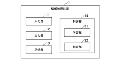
- FIG. 1 is a diagram showing an example of schematic functional blocks of an information processing apparatus 1 according to an embodiment.
- the information processing device 1 is a computer.
- the information processing apparatus 1 has a function of performing machine learning and a function of performing determination based on the result of the machine learning.
- the information processing device 1 may be configured as an integrated device as in the present embodiment, or may be configured as a plurality of separate devices. When the information processing device 1 is configured as a plurality of separate devices, two or more of these devices may communicate with each other directly or via a network. The communication may be wired communication or wireless communication. Further, when the information processing device 1 is configured as a plurality of separate devices, for example, a device that performs machine learning and a device that performs determination based on the result of the machine learning are provided as separate devices. good too.
- the information processing apparatus 1 shown in FIG. 1 will be described.
- the information processing device 1 includes an input unit 11 , an output unit 12 , a storage unit 13 and a control unit 14 .
- the control unit 14 includes a learning unit 31 and a determination unit 32 .
- the input unit 11 inputs information.
- the input unit 11 may have operation units such as a keyboard and a mouse.
- the input unit 11 inputs information corresponding to the operation performed on the operation unit by the user.
- the input unit 11 may input information from an external device.
- the external device may be, for example, a portable storage medium.
- the output unit 12 outputs information.
- the output unit 12 may have a display with a screen. In this case, the output unit 12 displays and outputs information on the screen.
- the output unit 12 may output information to an external device.
- the external device may be, for example, a portable storage medium.
- the storage unit 13 stores information.
- the control unit 14 performs various types of processing and control.
- the control unit 14 includes a processor such as a CPU (Central Processing Unit), and the processor executes a control program (program) to perform various types of processing and control.
- the control program is stored in the storage unit 13, for example.
- the learning unit 31 performs machine learning using a predetermined machine learning model.
- a result of machine learning is stored in the storage unit 13 .
- the determination unit 32 reads the machine learning result stored in the storage unit 13 . Then, the determining unit 32 performs determination using the machine learning model based on the read result of the machine learning.
- Machine learning model Any model may be used as the machine learning model.
- a case where a neural network is used as a machine learning model will be described, and more specifically, a case where a U-Net neural network is used will be described.
- FIG. 2 is a diagram illustrating an example of a neural network according to the embodiment;
- the information processing apparatus 1 performs machine learning using the neural network shown in FIG. 2, and makes determinations based on the results of the machine learning.
- the neural network shown in FIG. 2 is a U-Net convolutional neural network (CNN: Convolutional Neural Network) and has a U shape.
- CNN Convolutional Neural Network
- the neural network is not limited to U-Net, and other neural networks may be used.
- Other neural networks include, for example, ResNet (Residual Network).
- FIG. 2 An outline of the neural network shown in FIG. 2 will be described.
- square frames represent images or feature maps, and arrows represent various types of processing. Five types of arrows are used in FIG. 2, and each type of arrow represents a different process. Also, in FIG. 2, the numbers under the square frames indicate the number of channels.
- processing such as convolution is performed on the input image T1 to generate a feature map T2, and similar processing such as convolution is performed on the feature map T2 to generate a feature map T3.
- convolutions for example, convolution with a kernel size of 3 ⁇ 3 is performed, batch normalization is performed, and LeakyReLU, which is an activation function, is performed. It is not limited to this. For example, any size may be used as the convolution kernel size. Also, other functions may be used as the activation function.
- a pooling (also called downsampling) process is performed on the feature map T3 to generate a second layer feature map T11.
- the pooling process for example, a Max-pooling process with a kernel size of 2 ⁇ 2 is performed, but it is not limited to this.
- any size may be used as the kernel size for pooling.
- processing such as convolution is performed twice on the feature map T11, and then pooling processing is performed to obtain the third layer.
- a feature map T21 is generated.
- the feature map T31 of the 4th layer, the feature map T41 of the 5th layer, and the feature map T51 of the 6th layer are used. is shown.
- FIG. 2 shows a U-Net having a depth of the first to sixth layers
- the depth (the number of stages) is not limited to this.
- processing such as convolution is performed twice on the feature map T51 to generate a feature map T52.
- deconvolution also called upsampling
- processing is performed on the feature map T52 to generate a feature map T111 of the fifth layer.
- the deconvolution process for example, a deconvolution process with a kernel size of 2 ⁇ 2 is performed. Note that the deconvolution process corresponds to the inverse operation of the convolution process.
- the feature map T121 is generated by performing the Skip-Connection process on the result of performing the processing such as convolution twice on the feature map T41.
- copy processing is performed as skip connection processing.
- the feature map T121 corresponds to a copy of the result obtained by performing processing such as convolution twice on the feature map T41.
- crop processing may be performed as necessary.
- the result of integrating the feature map T121 in the fifth layer and the feature map T111 from the sixth layer is subjected to a process such as convolution twice to obtain a feature map T42. is generated.
- deconvolution processing is performed on the feature map T42 to generate a feature map of the fourth layer.
- the feature map is used to generate the final feature map T32 of the fourth layer.
- the example in FIG. 2 shows the final feature map T22 for the third layer and the final feature map T12 for the second layer. be.
- the feature map T141 generated by performing skip connection processing on the feature map T3 and the deconvolution processing on the feature map T12 of the second layer are generated. is integrated with the feature map T131. Then, the result of this integration is subjected to a first convolution or other processing to generate a feature map T211, and then a second convolution or other processing is performed to generate a feature map T212.
- final convolution processing is performed on the feature map T212 to generate an output image T213.
- the final convolution processing for example, convolution processing with a kernel size of 1 ⁇ 1 is performed.
- all the convolution processes other than the final convolution process are of the same kernel size.
- the U-Net neural network has two tower structures for downsampling and upsampling, and the output (feature map) from a certain depth layer to the next layer is By processing the skip connection in the layer one above and integrating it with the feature map of the layer one above, the reconstruction of the overall position information is realized while maintaining the local features.
- U-Net structure of the U-Net shown in FIG. 2 is an example, and is not limited to the example of FIG. 2, and U-Nets with other structures may be used.
- the input image is an OCT image that can be acquired with a normal OCT apparatus (a non-polarized OCT apparatus in this embodiment).
- a normal OCT apparatus non-polarized OCT apparatus in this embodiment
- an FD (Fourier Domain)-OCT apparatus or the like may be used.
- An example of an input image is a normal OCT image without polarization information (an example of a non-polarized OCT image in this embodiment).
- OCT of a normal OCT image is sometimes called, for example, conventional OCT, standard OCT, or scattering OCT.
- OCTA OCT Angiography
- OCTA is an image highlighting the vascular structure obtained by analyzing the time fluctuation of the OCT signal. OCTA is described, for example, in Non-Patent Document 1.
- An example of an input image is an image of attenuation coefficients.
- the attenuation coefficient is the amount of attenuation in the minute depth region of the OCT signal.
- the attenuation is related to tissue density and intensity of light absorption. The degree of attenuation is greater as the tissue density is higher, and greater as the absorption is stronger.
- the attenuation coefficient is described in Non-Patent Document 2, for example.
- the input image one input image may be used, or a plurality of input images may be used.
- these multiple input images may be, for example, images of the same part of the specimen measured at different times, or may be images of different parts in the vicinity of the specimen. It may be an image measured in time, or another image may be used.
- OCTA when OCTA is composed of a plurality of (for example, 4) image frames continuously captured in time series, not all of these plurality of image frames are necessarily used as input images. Often, a part (one or more but less than the total number) of these multiple image frames may be used.
- the output image is an image that can be acquired by a polarization OCT apparatus, which is special hardware, except that a polarization OCT image is generated from a non-polarization OCT image as in the information processing apparatus 1 according to this embodiment. is.
- Example 1 of output image An example of an output image is a (Cumulative) Phase Retardation image. Polarization retardation is described in Non-Patent Document 3 and Non-Patent Document 4, for example.
- An example of an output image is an image of local phase retardation. Local polarization retardation is described, for example, in Non-Patent Document 3 and Non-Patent Document 4.
- An example of an output image is a birefringence image.
- the value of birefringence here is a quantity related to the strength of birefringence possessed by tissue. Note that birefringence itself is a general concept. Birefringence is described, for example, in Non-Patent Document 4 and Non-Patent Document 5.
- Phase retardation is the phase difference between the two polarization states of OCT probe light caused by birefringence.
- Cumulative phase retardation is often referred to. This is the total polarization phase difference experienced by the probe light from the tissue surface to the measured depth.
- the local polarization retardation (local phase retardation) is the amount of local phase retardation in the vicinity of the measurement depth. This is proportional to the birefringence of that depth.
- birefringence described above does not directly represent the birefringence as a characteristic of tissue, but is defined by multiplying the local phase retardation by a theoretically obtained coefficient (constant). It is a thing. In the application of machine learning in this embodiment, birefringence and local phase retardation may be considered to be almost synonymous.
- An example of an output image is a polarization uniformity (DOPU) image.
- Polarization uniformity is described, for example, in Non-Patent Document 6 and Non-Patent Document 7.
- Example 5 of output image An example of an output image is a degree of polarization (DOP) image. Depolarization is described, for example, in Non-Patent Document 8.
- An example of an output image is an image of (Polarization) Shannon Entropy. (Polarization) Shannon entropy is described, for example, in Non-Patent Document 9.
- polarization uniformity, depolarization, and (polarized) Shannon entropy are all quantities that indicate variations in local polarization characteristics (in the vicinity of a tissue site) of polarized signals measured by a polarization OCT apparatus.
- Polarization uniformity and depolarization take values between 0 and 1 (although their mathematical definitions are different) and are almost the same.
- the (polarized) Shannon entropy takes a different value from these, but by definition it has a 1:1 correspondence (bijective relationship) with the polarization uniformity.
- An example of an output image is an image of the polarizing axis (Optic Axis). Polarization axes are described in Non-Patent Document 10, for example.
- polarization axis indicates the direction of the axis that is set with the amount of polarization such as Phase retardation.
- Phase retardation is the phase difference that occurs between these two unique polarization states.
- the direction of its unique polarization state is the polarizing axis (Optic Axis).
- Optic Axis There are two inherent polarization states, but since these are generally orthogonal, one of the two is often used as the polarizing axis (Optic Axis).
- Polarization axis uniformity is described, for example, in Non-Patent Document 11 and Non-Patent Document 12.
- Polarization axis uniformity is the uniformity of the polarization axis within a localized (ie, small) region of tissue.
- Example of hardware for measuring OCT images 1 illustrates hardware for measuring OCT images.
- Example 1 of hardware for measuring OCT images is a full-function polarization OCT apparatus.
- a full-featured polarization OCT apparatus is capable of capturing all of the above images (the input image above and the output image above).
- Full-featured polarization OCT devices are described, for example, in [3], [4] and [5].
- the attenuation coefficient is calculated by applying a predetermined algorithm (for example, the algorithm described in Non-Patent Document 2) to an OCT image obtained by a full-function polarization OCT apparatus.
- a predetermined algorithm for example, the algorithm used in Non-Patent Document 4
- can be applied. can be calculated with
- Example 2 of hardware for measuring OCT images there is a simplified polarization OCT apparatus (PAF-OCT apparatus).
- a simplified version of the polarization OCT apparatus is described, for example, in Non-Patent Document 13.
- a simplified version of the polarization OCT apparatus can capture some of the above images (the above input image and the above output image).
- Some of the images that cannot be captured include Cumulative phase retardation images, local phase retardation images, birefringence images, polarizing axis images, and polarizing axis uniformity images. Axis Uniformity).
- FIG. 3 is a diagram showing an example of a procedure of processing during learning performed in the information processing apparatus 1 according to the embodiment.
- the learning unit 31 of the control unit 14 learns the convolutional neural network shown in FIG. 2 using input images and teacher data (teacher images) that are correct values of output images (step S1). Then, in the information processing device 1, the learning unit 31 of the control unit 14 stores the learning result in the storage unit 13 (step S2).
- DCNN Deep CNN
- validation and testing may be performed on the learning result.
- a non-polarized OCT image having no polarization information is used as the input image.
- a polarization OCT image having polarization information is used as a teacher image for the output image.
- the input image (non-polarization OCT image) and the teacher image (polarization OCT image) are obtained from the results of measurement by the same polarization OCT apparatus.
- the positions of the input image and the teacher image match each other at the pixel level (that is, they are registered).
- the input image (non-polarized OCT image) may be measured by a non-polarized OCT device
- the teacher image (polarized OCT image) may be measured by a polarized OCT device.
- processing is performed to match the registration of the input image (non-polarized OCT image) and the teacher image (polarized OCT image).
- the input image may be measured by a polarized OCT device
- the teacher image polarized OCT image
- processing is performed to match the registration of the input image (non-polarized OCT image) and the teacher image (polarized OCT image).
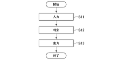
- FIG. 4 is a diagram illustrating an example of a procedure of determination processing performed in the information processing apparatus 1 according to the embodiment.
- the determination unit 32 of the control unit 14 inputs an input image (non-polarized OCT image) to be determined (step S11).
- the determination unit 32 of the control unit 14 determines an output image (pseudo polarization OCT image) for the input image based on the learning result stored in the storage unit 13 (step S12).
- the determination unit 32 of the control unit 14 outputs the determined output image by display or the like (step S13).
- a non-polarized OCT image measured by a non-polarized OCT apparatus is used as an input image (non-polarized OCT image).
- the information processing apparatus 1 can obtain an output image (pseudo polarized OCT image) from an input image (non-polarized OCT image) based on the learning result. That is, a pseudo polarized OCT image is generated from a non-polarized OCT image measured by a non-polarized OCT apparatus.
- a simple polarization OCT apparatus (PAF-OCT apparatus) described in Non-Patent Document 13 is used to generate a non-polarization OCT image consisting of an intensity signal and a polarization OCT image serving as a teacher image as a correct value. got both. That is, in this specific example, an input image (non-polarization OCT image) and a teacher image (polarization OCT image) are acquired by the same polarization OCT device, and machine learning is performed.
- the center wavelength (Center Wavelength) in the polarization OCT apparatus is 1 ⁇ m.
- the sweep rate in the polarization OCT apparatus is 100,000 A-lines/s.
- the sensitivity in the polarization OCT apparatus is 89.5 dB.
- a non-polarized OCT image composed of intensity signals obtained by a simple polarized OCT apparatus (PAF-OCT apparatus) described in Non-Patent Document 13 was used as an input image.
- a DOPU image was calculated from signals of two polarization channels acquired by a simple polarization OCT apparatus (PAF-OCT apparatus) described in Non-Patent Document 13. This DOPU image was used as a teacher image during learning. Also, this DOPU image was used to evaluate the accuracy of the judgment based on the learning result.
- a non-polarized OCT image composed of intensity signals is obtained by combining complex OCT signals of two polarization channels obtained by a simple polarization OCT apparatus (PAF-OCT apparatus) described in Non-Patent Document 13 with each channel. It was calculated by summing after correcting for the constant phase between and taking the square of the absolute value.
- PAF-OCT apparatus simple polarization OCT apparatus
- the output image (pseudo-DOPU image) that is the result of the determination based on the learning result may be called a pDOPU image (pseudo-DOPU image).
- Retinal data measured during a predetermined period (February 2019 to September 2020) was used for learning.
- 117 eyes from 96 patients and 4 normal eyes from 4 were examined.
- 105 diseased eyes were used in neural network training.
- a non-polarized OCT image consisting of intensity signals from a B-scan and a DOPU image from a B-scan were each extracted as an image patch of (64 ⁇ 64) pixels.
- a total of 5000 image patches were then generated. 4000 image patches out of these 5000 image patches were used for learning to update parameters (eg, parameters such as weights) of the neural network.
- the remaining 1000 image patches were used for validation.
- the remaining 12 diseased and 4 normal eye image patches were also used as the test data set.
- ⁇ Evaluation method> A trained ophthalmologist selected the abnormal regions using unpolarized OCT images of the test dataset for the diseased eye. Five B-scan images were then randomly selected from the abnormal region of each test eye.
- B-scan DOPU and pDOPU images were provided to another trained rater. This rater then independently and visually assessed the DOPU and pDOPU images for the given symptoms.
- RPE defect, RPE thickening, RPE elevation, and hyper-reflective foci (HRF) were used as the predetermined symptoms.
- the information processing apparatus 1 uses a non-polarized OCT image made up of an intensity signal as an input image based on the results of machine learning using the convolutional neural network shown in FIG. to generate
- OCT images are shown below with reference to FIGS. 5A to 5C, 6A to 6C, 7A to 7C, 8A to 8C, and 9A to 9C.
- the DOPU image and the pDOPU image are originally color images, but are shown as black and white grayscale images for convenience of illustration.
- the images are B-scan images.
- FIG. 5A is a diagram showing an example of a non-polarized OCT image 111 consisting of intensity signals for a normal eye.
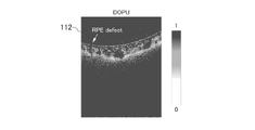
- FIG. 5B is a diagram showing an example of the DOPU image 112 for a normal eye. In FIG. 5B, the location of the RPE defect is indicated by an arrow as "RPE defect”.
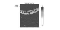
- FIG. 5C is a diagram showing an example of a pDOPU image 113 for a normal eye.
- FIG. 6A is an example of an unpolarized OCT image 131 of intensity signals for a diseased eye.
- FIG. 6B is an example DOPU image 132 for a diseased eye.
- FIG. 6C is an example of a pDOPU image 133 for a diseased eye.
- RPE defects were found in both DOPU image 132 and pDOPU image 133, as shown in FIGS. 6B and 6C.
- FIG. 6B and FIG. 6C the location of the RPE defect is indicated by an arrow as "RPE defect".
- FIG. 7A is an example of an unpolarized OCT image 151 of intensity signals for a diseased eye.
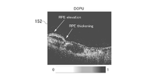
- FIG. 7B is an example DOPU image 152 for a diseased eye.
- FIG. 7C is an example of a pDOPU image 153 for a diseased eye.
- RPE elevation and RPE thickening were found in both DOPU image 152 and pDOPU image 153, as shown in FIGS. 7B and 7C.
- the locations of the respective abnormalities are indicated by arrows as "RPE elevation” and "RPE thickening”.
- the pDOPU image 153 is indicated by an arrow indicating "RPE defect", but this is an erroneous observation.
- FIG. 8A is an example of an unpolarized OCT image 171 of intensity signals for a diseased eye.
- FIG. 8B is an example DOPU image 172 for a diseased eye.
- FIG. 8C is an example of a pDOPU image 173 for a diseased eye.
- RPE elevation, RPE thickening, and HRF were found in both the DOPU image 172 and the pDOPU image 173, as shown in FIGS. 8B and 8C. Regarding these, in FIGS. 8B and 8C, the locations of respective abnormalities are indicated by arrows as "RPE elevation”, “RPE thickening", and "HRF".
- FIG. 9A is an example of an unpolarized OCT image 191 of intensity signals for a diseased eye.
- FIG. 9B is an example DOPU image 192 for a diseased eye.
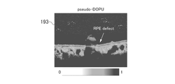
- FIG. 9C is an example of a pDOPU image 193 for a diseased eye.
- RPE elevation and HRF were found in the DOPU image 192, as shown in FIG. 9B.
- the locations of the respective abnormalities are indicated by arrows as "RPE elevation” and "HRF”.
- no RPE elevation and no HRF were found in the pDOPU image 193, as shown in FIG. 9C.
- the pDOPU image 193 is indicated by an arrow indicating "RPE defect", but this is an erroneous observation.
- FIG. 10 shows a table 1011 representing the number of clinical features analyzed for DOPU and pDOPU images.
- Table 1011 summarizes the number of clinical features analyzed by ophthalmologists independently for each of the DOPU and pDOPU images for diseased eyes.
- the clinical features are RPE defect, RPE thickening, RPE elevation, and HRF, respectively.
- the number of RPE defects that were positive in both DOPU and pDOPU images was 15. Regarding the RPE defect, the number of positive on DOPU images and negative on pDOPU images was 11. For the RPE defect, the number of negative on DOPU images and positive on pDOPU images is 16. The number of negatives on both DOPU and pDOPU images is unknown.
- RPE thickening 21 were positive in both DOPU and pDOPU images.
- the number of positive on DOPU images and negative on pDOPU images was 3.
- the number of negative on DOPU images and positive on pDOPU images is 4.
- the number of negatives on both DOPU and pDOPU images is unknown.
- RPE elevation 25 were positive on both DOPU and pDOPU images.
- the number of positive on DOPU images and negative on pDOPU images is 4.
- the number of negative on DOPU images and positive on pDOPU images is one.
- the number of negatives on both DOPU and pDOPU images is unknown.
- the number of positives in both DOPU and pDOPU images is 2.
- the number of positive on DOPU images and negative on pDOPU images is nine.
- the number of negative DOPU images and positive pDOPU images is 5.
- the number of negatives on both DOPU and pDOPU images is unknown.
- the coincidence of the determined abnormalities between the DOPU image and the pDOPU image was 35.7%.
- the degree of agreement between the DOPU image and the pDOPU image was 75.0%.
- the degree of agreement between the determined abnormalities in the DOPU image and the pDOPU image was 83.3%.
- the degree of agreement between the DOPU image and the pDOPU image for the determined abnormalities was 12.5%.
- the pDOPU image gave results close to the actual DOPU image, especially with respect to RPE thickening and RPE elevation.
- the degree of matching with the actual DOPU image is lower for RPE defect and HRF than for RPE thickening and RPE elevation, but it is believed that further learning will improve the degree of matching. be done.
- pDOPU images tended to have less RPE defect noise than DOPU images.
- the information processing apparatus 1 can perform learning for generating an image (pseudo-polarized OCT image) equivalent to a polarized OCT image from a non-polarized OCT image. Further, the information processing apparatus 1 according to the present embodiment can generate an image (pseudo-polarized OCT image) equivalent to the polarized OCT image from the non-polarized OCT image based on the learning result.
- the information processing apparatus 1 can acquire a pseudo polarized OCT image from a non-polarized OCT image.
- a pseudo polarized OCT image for example, an image equivalent to a polarized OCT image (pseudo-polarized OCT images) can be acquired.
- an image equivalent to a polarized OCT image can be generated using a non-polarized OCT image obtained from a non-polarized OCT apparatus that has already been widely used.
- the information processing apparatus 1 in a medical facility using a non-polarization OCT apparatus, can convert a non-polarization OCT image into an image equivalent to a polarization OCT image without purchasing an expensive polarization OCT apparatus. can be obtained and diagnosed.
- the medical facility may utilize conventional image processing and diagnostic algorithms that have been developed for polarized OCT images.
- the information processing apparatus 1 according to the present embodiment may be applied, for example, to image diagnosis in ophthalmology (particularly fundus disease) and image diagnosis in the circulatory system (coronary arteries).
- the information processing apparatus 1 according to the present embodiment may be applied, for example, to regenerative medicine cultured tissue, quality control of organoids, animal experiments, and efficacy evaluation when measuring efficacy using cultured tissue.
- the information processing apparatus 1 according to the present embodiment may be applied to improve the efficiency of drug development by using it for animal experiments, for example.
- an image showing pigment epithelial abnormalities by analyzing a non-polarized OCT image obtained by a non-polarized OCT apparatus of the fundus that is already in widespread use. This is expected to facilitate the diagnosis of age-related macular degeneration and Harada disease.
- a non-polarized OCT apparatus for coronary artery catheters which has already been covered by health insurance. This allows discrimination related to atherosclerotic material risk.
- a non-polarizing OCT apparatus here, a non-polarizing OCT microscope
- This can accelerate the adoption of the OCT microscope as a development tool for melanin-acting drugs and cosmetics.
- a program for realizing the functions of any component in any device described above may be recorded in a computer-readable recording medium, and the program may be read and executed by a computer system.
- the "computer system” here includes an operating system (OS) or hardware such as peripheral devices.
- OS operating system
- computer-readable recording medium refers to portable media such as flexible discs, magneto-optical discs, ROMs, CD (Compact Disc)-ROMs, and storage devices such as hard disks built into computer systems.
- “computer-readable recording medium” means a volatile memory (RAM) inside a computer system that acts as a server or client when a program is transmitted via a network such as the Internet or a communication line such as a telephone line. , includes those that hold the program for a certain period of time.
- the above program may be transmitted from a computer system storing this program in a storage device or the like to another computer system via a transmission medium or by a transmission wave in a transmission medium.
- the "transmission medium" for transmitting the program means a medium having a function of transmitting information, such as a network such as the Internet or a communication line such as a telephone line.
- the above program may be for realizing part of the functions described above.
- the above program may be a so-called difference file, which can realize the functions described above in combination with a program already recorded in the computer system.
- a difference file may be referred to as a difference program.
- any component in any device described above may be realized by a processor.
- each process in the embodiment may be implemented by a processor operating based on information such as a program and a computer-readable recording medium storing information such as the program.
- the function of each section may be implemented by separate hardware, or the function of each section may be implemented by integrated hardware.
- a processor includes hardware, which may include at least one of circuitry that processes digital signals and circuitry that processes analog signals.
- a processor may be configured using one or more circuit devices and/or one or more circuit elements mounted on a circuit board.
- An IC (Integrated Circuit) or the like may be used as the circuit device, and a resistor, capacitor, or the like may be used as the circuit element.
- the processor may be, for example, a CPU.
- the processor is not limited to a CPU, and various processors such as a GPU (Graphics Processing Unit) or a DSP (Digital Signal Processor) may be used.
- the processor may be, for example, a hardware circuit based on ASIC (Application Specific Integrated Circuit).
- the processor may be composed of, for example, a plurality of CPUs, or may be composed of a plurality of ASIC hardware circuits.
- the processor may be configured by, for example, a combination of multiple CPUs and multiple ASIC hardware circuits.
- the processor may also include, for example, one or more of amplifier circuits, filter circuits, etc. that process analog signals.
- the information processing apparatus 1 receives as input one or more non-polarized OCT images, which are OCT images that do not have polarization information.
- a learning unit 31 that performs learning of a machine learning model that outputs a typical polarized OCT image, and a storage unit 13 that stores the learning result of the learning unit 31 .
- the machine learning model is a convolutional neural network model.
- the input image for the machine learning model is a normal OCT image, an OCTA image, or an attenuation coefficient image.
- the output image of the machine learning model is a polarization phase difference, local polarization phase difference, birefringence, polarization uniformity, depolarization, Shannon entropy, polarization axis, or a pseudo image of polarization axis uniformity.
- the non-polarized OCT image and the polarized OCT image serving as the teacher image for learning are images acquired by a single polarized OCT apparatus.
- one or more non-polarized OCT images which are OCT images that do not have polarization information, are input to a computer (in this embodiment, the computer that constitutes the information processing apparatus 1), and the It is a program for learning a machine learning model that outputs a pseudo polarized OCT image corresponding to a polarized OCT image that is an existing OCT image, and storing the learning result in the storage unit 13 .
- the information processing apparatus 1 receives as input one or more non-polarized OCT images, which are OCT images that do not have polarization information. Based on the storage unit 13 that stores the learning results of the machine learning model that outputs a typical polarized OCT image, and the learning results stored in the storage unit 13, the machine learning model converts the non-polarized OCT image that is the input image into and a determination unit 32 that determines a pseudo polarized OCT image accordingly.
- the machine learning model is a convolutional neural network model.
- the input image for the machine learning model is a normal OCT image, an OCTA image, or an attenuation coefficient image.
- the output image of the machine learning model is a polarization phase difference, local polarization phase difference, birefringence, polarization uniformity, depolarization, Shannon entropy, polarization axis, or a pseudo image of polarization axis uniformity.
- the non-polarization OCT image is an image acquired by a non-polarization OCT apparatus.
- one or more non-polarized OCT images which are OCT images that do not have polarization information, are input to a computer (in this embodiment, the computer that constitutes the information processing apparatus 1), and the The learning result stored in the storage unit 13 that stores the learning result of the machine learning model that outputs the pseudo polarized OCT image corresponding to the polarized OCT image that is the OCT image that is present is read, and the read learning result is read.
- [Modification] 4 shows a modification of the embodiment.
- an information processing apparatus 1 according to the modified example will be described using FIG. 1 .
- the reference numerals shown in FIG. 1 are used for explanation.
- the information processing device 1 acquires information on the learning result of machine learning stored in an external device, and the determination unit 32 makes a determination based on the acquired information on the learning result. show.
- the external device may be any device, such as a server device provided in a network such as the Internet.
- the information processing device 1 communicates with the server device or the like via the network, receives information on the learning result of machine learning from the server device, and uses the received information for determination by the determination unit 32.
- the communication may be, for example, wired communication or wireless communication.
- the external device may be, for example, a device that provides a service of providing information on learning results of machine learning.
- the service may be a paid service or a free service.
- Information on learning results of machine learning may be stored in a storage device such as a database that can be accessed by the external device, for example. Also, the information on the learning result of machine learning may be updated at any timing.
- the information processing device 1 may access the external device and receive information on the learning result of machine learning from the external device when necessary. For example, the information processing device 1 accesses the external device in response to an instruction from a person (user) who operates the information processing device 1, and receives information on the result of machine learning from the external device. Alternatively, when a predetermined condition is satisfied, the external device may be automatically accessed to receive machine learning result information from the external device.
- the information processing device 1 may store information received from the external device in the storage unit 13 .
- the information provided from the external device may be temporarily stored in the storage unit 13 of the information processing device 1 for reference, but may not be stored in the long term.
- the information processing device 1 accesses the external device and receives information on the result of machine learning from the external device whenever necessary.
- a system including the information processing device 1 and the external device may be implemented.
- the information processing device 1 may acquire information on the learning result of machine learning from an external device, and the determination unit 32 may make a determination based on the acquired information.
- the information processing apparatus 1 does not have to include the learning unit 31 in this modification.
- the information processing apparatus 1 does not have a function of performing machine learning and a function of storing information on the learning result of machine learning, but uses the information of the learning result of machine learning received from the outside to perform determination by the determination unit 32. may be performed.
- the information processing apparatus 1 receives as input one or more non-polarized OCT images that are OCT images that do not have polarization information, and based on the learning results of the machine learning model, the input image A determining unit 32 that determines a pseudo polarized OCT image corresponding to a polarized OCT image, which is an OCT image having polarization information, according to the non-polarized OCT image.
- a computer in this modification, a computer that constitutes the information processing apparatus 1 is caused to acquire the learning result of the machine learning model, and one or more non-polarized OCT images that are OCT images that do not have polarization information.
- An image is input, and based on the obtained learning result, a machine learning model generates a pseudo-polarized OCT image corresponding to the polarized OCT image, which is an OCT image having polarization information, according to the non-polarized OCT image, which is the input image.
- a program for determining a polarized OCT image is performed by the machine learning model to acquire the learning result of the machine learning model, and one or more non-polarized OCT images that are OCT images that do not have polarization information.
- the information processing device 1 has a function of performing machine learning by the learning unit 31, and transmits information of the learning result of the machine learning to an external device (for example, an external storage device), and transmits the information to the external device.
- an external device for example, an external storage device
- the external device may be provided at any location, for example, may be provided so as to be directly connectable to the information processing device 1, or may be connected to the information processing device 1 via a network such as the Internet. It may be provided so as to be communicatively connectable.
- the information processing apparatus 1 accesses the external device and receives and uses information on the learning result of machine learning from the external device.
- a system including the information processing device 1 and the external device may be implemented.
- the determination unit 32 may use the function of an external device to perform determination (acquisition of determination results as an example of determination in this modified example). For example, when determining output information corresponding to input information, the determination unit 32 transmits the input information to the external device, and receives the output information obtained by the external device from the external device. , and the acquired output information may be used as the determination result.
- the external device has a function of obtaining information (output information) corresponding to information (input information) received from the information processing device 1 .
- the external device generates information according to information (input information) received from the information processing device 1 by the machine learning model based on information on the learning result of machine learning using a predetermined machine learning model. (output information) is determined by judgment.
- the external device provides, for example, transmission information (output information from the machine learning model) responding to the information processing device 1 in response to information received from the information processing device 1 (input information to the machine learning model). It may be a device that provides a service.
- the service may be a paid service or a free service.
- the information processing device 1 may transmit information on the results of machine learning performed by the learning unit 31 (which may be stored in the storage unit 13) to the external device.
- the external device uses the information received from the information processing device 1 to obtain information (output information) corresponding to the information (input information) received from the information processing device 1 .
- the external device may store the information received from the information processing device 1 in a storage device such as a database.
- the information processing device 1 may not have the function of the learning section 31 .
- the information processing apparatus 1 does not have to have the function of performing machine learning and the function of storing information on the learning result of the machine learning.
- the external device stores information on the results of machine learning in a storage device such as a database.
- the external device may be provided in a network such as the Internet and communicate with the information processing device 1 via the network.
- the communication may be, for example, wired communication or wireless communication.
- a system including the information processing device 1 and the external device may be implemented.
- the information processing apparatus 1 has a function of performing machine learning and a function of storing information on learning results of the machine learning, but does not have to have the function of the determination unit 32 .
- the information processing device 1 may provide (for example, transmit) the information of the learning result of the machine learning stored in the storage unit 13 to the other device, for example.
- a system for example, an information processing system including an information processing device 1 having a function of performing machine learning and another device (for example, another information processing device) that makes a determination based on the learning result of the machine learning ) may be implemented.
- the DOPU image is originally a color image, but for convenience of illustration, it is shown as a black and white grayscale image. Also, in the following examples, the images are B-scan images.
- model 1 Model 1
- Model 2 Model 2
- the method of model 1 is the method of the above-described embodiment, and is a method of inputting an OCT image at the time of learning and judgment of the machine learning model.
- the method of model 2 is a method of this modified example, and is a method of inputting a combination of an OCT image and an OCTA image as multi-channel images at the time of learning and judgment of a machine learning model.
- FIG. 11A is a diagram showing an example of an OCT image 311 used in model 1 and model 2.
- FIG. 11B is a diagram showing an example of an OCTA image 312 used in Model 2.
- FIG. 11C is a diagram showing an example of a true DOPU image 313 that is a true DOPU image used in model 1 and model 2.
- FIG. 11D is a diagram showing an example of a pseudo DOPU image 314 generated by the Model 1 technique.
- FIG. 11E is a diagram showing an example of a pseudo DOPU image 315 generated by the Model 2 technique.
- the OCT image 311 was used as an input and the true DOPU image 313 was used as a true value (teacher image) in the machine learning model. Then, in the method of Model 1, a pseudo DOPU image 314 was generated.
- the OCT image 311 and the OCTA image 312 were used as inputs, and the true DOPU image 313 was used as the true value (teacher image). Then, in the method of model 2, a pseudo DOPU image 315 was generated.
- the pseudo DOPU image 315 obtained by the method of model 2 is closer to the true DOPU image 313 than the pseudo DOPU image 314 obtained by the method of model 1.
- the model 2 method improved the accuracy of generating the pseudo DOPU image compared to the model 1 method.
- FIG. 11C shows, for the true DOPU image 313, a predetermined portion 321a of the object included in the image and an enlarged image (enlarged image 321b) of the predetermined portion 321a.
- FIG. 11D shows a predetermined portion 322a of the target object and an enlarged image (enlarged image 322b) of the predetermined portion 322a for the pseudo DOPU image 314 generated by the Model 1 method.
- FIG. 11E shows a predetermined portion 323a of the target object and an enlarged image (enlarged image 323b) of the predetermined portion 323a for the pseudo DOPU image 315 generated by the method of Model 2.
- FIG. 11C shows, for the true DOPU image 313, a predetermined portion 321a of the object included in the image and an enlarged image (enlarged image 321b) of the predetermined portion 321a.
- FIG. 11D shows a predetermined portion 322a of the target object and an enlarged image (enlarged image 322b) of the predetermined portion 322a for the pseudo DOPU
- these predetermined portions are the same portion of the same object.
- 11C to 11E it can be understood that the method of model 2 is higher in the accuracy of generating the pseudo DOPU image than the method of model 1.
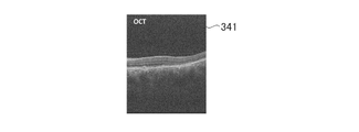
- FIG. 12A is a diagram showing an example of an OCT image 341 used in model 1 and model 2.
- FIG. 12B is a diagram showing an example of an OCTA image 342 used in Model 2.
- FIG. 12C is a diagram showing an example of a true DOPU image 343 that is a true DOPU image used in model 1 and model 2.
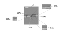
- FIG. 12D is a diagram showing an example of a pseudo DOPU image 344 generated by the Model 1 technique.
- FIG. 12E is a diagram showing an example of a pseudo DOPU image 345 generated by the Model 2 technique.
- the OCT image 341 is used as an input and the true DOPU image 343 is used as a true value (teacher image) in the machine learning model. Then, in the method of Model 1, a pseudo DOPU image 344 was generated. In the method of model 2, in the machine learning model, the OCT image 341 and the OCTA image 342 were used as inputs, and the true DOPU image 343 was used as the true value (teacher image). Then, in the method of model 2, a pseudo DOPU image 345 was generated.
- the pseudo DOPU image 345 obtained by the model 2 method is closer to the true DOPU image 343 than the pseudo DOPU image 344 obtained by the model 1 method.
- the model 2 method improved the accuracy of generating the pseudo DOPU image compared to the model 1 method.
- FIG. 12C shows three predetermined portions 351a, 352a, and 353a of an object included in the image, and an enlarged image (three portions) of the three predetermined portions 351a, 352a, and 353a. Enlarged images 351b, 352b, 353b) of are shown.
- FIG. 12D shows three predetermined portions 354a, 355a, and 356a of the object and an enlarged view of these three predetermined portions 354a, 355a, and 356a for the pseudo DOPU image 344 generated by the method of Model 1. , and (3 enlarged images 354b, 355b, 356b).
- FIG. 12C shows three predetermined portions 351a, 352a, and 353a of an object included in the image, and an enlarged image (three portions) of the three predetermined portions 351a, 352a, and 353a. Enlarged images 351b, 352b, 353b) of are shown.
- FIG. 12D shows three predetermined portions 354a,
- 12E shows three predetermined portions 357a, 358a, and 359a of the object and an enlarged view of these three predetermined portions 357a, 358a, and 359a for the pseudo DOPU image 345 generated by the method of Model 2. 357b, 358b, and 359b) are shown.
- the first predetermined portion (predetermined portion 351a, predetermined portion 354a, predetermined portion 357a) of these three locations is the same portion of the same object.
- the second predetermined portion (predetermined portion 352a, predetermined portion 355a, predetermined portion 358a) of these three locations is the same portion of the same object.
- the third predetermined portion (predetermined portion 353a, predetermined portion 356a, predetermined portion 359a) of these three locations is the same portion of the same object.
- FIGS. 12C to 12E it can be understood that the method of model 2 has higher pseudo DOPU image generation accuracy than the method of model 1.
- FIG. 13A is a diagram showing an example of an OCT image 371 used in model 1 and model 2.
- FIG. 13B is a diagram showing an example of an OCTA image 372 used in Model 2.
- FIG. 13C is a diagram showing an example of a true DOPU image 373 that is a true DOPU image used in model 1 and model 2.
- FIG. 13D is a diagram showing an example of a pseudo DOPU image 374 generated by the Model 1 technique.
- FIG. 13E is a diagram showing an example of a pseudo DOPU image 375 generated by the Model 2 technique.
- the OCT image 371 was used as an input and the true DOPU image 373 was used as a true value (teacher image) in the machine learning model. Then, in the method of Model 1, a pseudo DOPU image 374 was generated. In the method of model 2, in the machine learning model, the OCT image 371 and the OCTA image 372 were used as inputs, and the true DOPU image 373 was used as the true value (teacher image). Then, in the method of model 2, a pseudo DOPU image 375 was generated.
- the pseudo DOPU image 375 obtained by the method of model 2 is closer to the true DOPU image 373 than the pseudo DOPU image 374 obtained by the method of model 1.
- the model 2 method improved the accuracy of generating the pseudo DOPU image compared to the model 1 method.
- FIG. 13C shows, for the true DOPU image 373, a predetermined portion 381a of the object included in the image and an enlarged image (enlarged image 381b) of the predetermined portion 381a.
- FIG. 13D shows a predetermined portion 382a of the object and an enlarged image (enlarged image 382b) of the predetermined portion 382a for the pseudo DOPU image 374 generated by the Model 1 technique.
- FIG. 13E shows a predetermined portion 383a of the object and an enlarged image (enlarged image 383b) of the predetermined portion 383a in the pseudo DOPU image 375 generated by the Model 2 method.
- predetermined portion 381a, predetermined portion 382a, predetermined portion 383a are the same portion of the same object. Then, as shown in FIGS. 13C to 13E, it can be understood that the method of model 2 has higher accuracy in generating the pseudo DOPU image than the method of model 1.
- FIG. 13C to 13E it can be understood that the method of model 2 has higher accuracy in generating the pseudo DOPU image than the method of model 1.
- a machine learning model for inputting multi-channel (2-channel) images is used, and an OCT image and an OCTA image are used as multi-channel (2-channel) inputs.
- other modes may be used as the types of multiple images to be combined.
- a combination of an OCT image and an attenuation coefficient image as multi-channel (2-channel) input may be used, or an OCTA image and an attenuation coefficient image as multi-channel (2-channel) input.
- a combination may be used.
- a machine learning model that inputs a multi-channel (3-channel) image is used, and an OCT image, an OCTA image, and an attenuation coefficient image are used as multi-channel (3-channel) inputs.
- a combination may be used.
- a mode of combining two or more images the case of using these two or more images as multi-channel images was shown.
- a configuration may be used in which an image obtained by performing an inter-image operation on these two or more images is used.
- an image resulting from the inter-image operation is used as an input image to the machine learning model in the above-described embodiment.
- inter-image operation for example, an operation of "adding” two or more images, an operation of "multiplying” two or more images, or an operation of "subtracting” two or more images are used. good too. Further, as the inter-image operation, for example, a mode of performing bit operation on two or more images may be used.
- addition, multiplication, or subtraction of respective pixel data at the same position in the subject is performed to obtain the result of the inter-image operation.
- image may be generated.
- addition, multiplication, or subtraction of pixel data is performed, for example, these operation results may be normalized.
- averaging of pixel data may be performed as one mode of addition of pixel data.
- the input image of the machine learning model may be a combination of two or more of the ordinary OCT image, the OCTA image, or the attenuation coefficient image.
- a combination of two or more images for example, a mode in which these two or more images are used as a multi-channel image may be used, or a predetermined operation may be performed on these two or more images.
- a mode of using an image obtained by slicing may also be used.
- both of the above two aspects may be used simultaneously as a combination of two or more images, that is, while the input of the machine learning model is a plurality of images (multichannel images), these multiple images
- a configuration may be used in which one or more of the images are images obtained by performing predetermined calculations on two or more types of images.
- noise is intentionally (numerically) added to the input image at the time of learning to promote generalization of the network.
- the numerical noise added to the image may be noise added to the image intensity.
- the numerical noise added to the image may also be complex noise added to the complex OCT signal. This complex noise may mimic, for example, a physical noise distribution that takes into account the physical imaging principle of OCT.
- the numerical noise added to the image may be a combination of two or more of the various types of noise as described above.
- a data augmentation method which is a general method used in machine learning, may be used.
- the input image to which noise is added may be any type of image used as the input image during learning.
- the technique may be used, for example, to generate an image with added noise based on physical principles (eg, an image generated by adding complex noise to the complex OCT signal described above). Although some physical noise can be reproduced without using this method, more appropriate noise can be added to the image by using this method.
- (Configuration example 1) Machine learning in which one or more non-polarized OCT images, which are OCT images without polarization information, are input and a pseudo-polarized OCT image corresponding to the polarized OCT image, which is an OCT image with polarization information, is output.
- a learning unit that learns the model;
- a storage unit that stores learning results of the learning unit;
- Information processing device
- the input image of the machine learning model is a normal OCT image, an OCTA image, an attenuation coefficient image, or an image of a combination of two or more thereof;
- the output image of the machine learning model is a polarization phase difference, local polarization phase difference, birefringence, polarization uniformity, depolarization, Shannon entropy, polarization axis, or a pseudo image of polarization axis uniformity.
- the information processing apparatus according to (configuration example 1) or (configuration example 2).
- the non-polarized OCT image and the polarized OCT image serving as the training teacher image are images acquired by a single polarized OCT device,
- the information processing apparatus according to any one of (configuration example 1) to (configuration example 3).
- One or more non-polarized OCT images that are OCT images that do not have polarization information are input, Based on the learning result of the machine learning model, the machine learning model generates a pseudo polarized OCT image corresponding to the polarized OCT image, which is an OCT image having polarization information, according to the non-polarized OCT image, which is the input image.
- a determination unit that determines Information processing equipment.
- (Configuration example 6) Furthermore, a storage unit that stores the learning results of the machine learning model that receives one or more non-polarized OCT images and outputs a pseudo-polarized OCT image, The determination unit determines a pseudo polarized OCT image according to the non-polarized OCT image that is the input image by the machine learning model based on the learning result stored in the storage unit.
- the information processing apparatus according to (Configuration example 5).
- the input image of the machine learning model is a normal OCT image, an OCTA image, an attenuation coefficient image, or an image of a combination of two or more thereof;
- the output image of the machine learning model is a polarization phase difference, local polarization phase difference, birefringence, polarization uniformity, depolarization, Shannon entropy, polarization axis, or a pseudo image of polarization axis uniformity.
- the information processing apparatus according to any one of (configuration example 5) to (configuration example 7).
- the non-polarized OCT image is an image acquired by a non-polarized OCT device,
- the information processing apparatus according to any one of (configuration example 5) to (configuration example 8).
Landscapes
- Engineering & Computer Science (AREA)
- Health & Medical Sciences (AREA)
- Life Sciences & Earth Sciences (AREA)
- Physics & Mathematics (AREA)
- General Health & Medical Sciences (AREA)
- Medical Informatics (AREA)
- General Physics & Mathematics (AREA)
- Theoretical Computer Science (AREA)
- Nuclear Medicine, Radiotherapy & Molecular Imaging (AREA)
- Radiology & Medical Imaging (AREA)
- Heart & Thoracic Surgery (AREA)
- Biophysics (AREA)
- Ophthalmology & Optometry (AREA)
- Biomedical Technology (AREA)
- Molecular Biology (AREA)
- Surgery (AREA)
- Animal Behavior & Ethology (AREA)
- Public Health (AREA)
- Veterinary Medicine (AREA)
- Computer Vision & Pattern Recognition (AREA)
- Quality & Reliability (AREA)
- Image Analysis (AREA)
- Eye Examination Apparatus (AREA)
Priority Applications (2)
| Application Number | Priority Date | Filing Date | Title |
|---|---|---|---|
| JP2023518685A JP7836100B2 (ja) | 2021-05-06 | 2022-04-28 | 情報処理装置およびプログラム |
| US18/558,290 US20240366084A1 (en) | 2021-05-06 | 2022-04-28 | Information processing device and program |
Applications Claiming Priority (2)
| Application Number | Priority Date | Filing Date | Title |
|---|---|---|---|
| JP2021078457 | 2021-05-06 | ||
| JP2021-078457 | 2021-05-06 |
Publications (1)
| Publication Number | Publication Date |
|---|---|
| WO2022234828A1 true WO2022234828A1 (ja) | 2022-11-10 |
Family
ID=83932769
Family Applications (1)
| Application Number | Title | Priority Date | Filing Date |
|---|---|---|---|
| PCT/JP2022/019407 Ceased WO2022234828A1 (ja) | 2021-05-06 | 2022-04-28 | 情報処理装置およびプログラム |
Country Status (3)
| Country | Link |
|---|---|
| US (1) | US20240366084A1 (https=) |
| JP (1) | JP7836100B2 (https=) |
| WO (1) | WO2022234828A1 (https=) |
Cited By (2)
| Publication number | Priority date | Publication date | Assignee | Title |
|---|---|---|---|---|
| WO2024190161A1 (ja) * | 2023-03-16 | 2024-09-19 | 株式会社トーメーコーポレーション | 教師データ生成システム、機械学習システム、octシステム、教師データ生成方法および教師データ生成プログラム |
| WO2024232288A1 (ja) * | 2023-05-08 | 2024-11-14 | 株式会社ニデック | 眼科画像処理プログラムおよび眼科画像処理装置 |
Citations (1)
| Publication number | Priority date | Publication date | Assignee | Title |
|---|---|---|---|---|
| WO2020003524A1 (ja) * | 2018-06-29 | 2020-01-02 | 株式会社ニデック | 眼科画像処理装置、oct装置、眼科画像処理プログラム、および、数学モデル構築方法 |
Family Cites Families (3)
| Publication number | Priority date | Publication date | Assignee | Title |
|---|---|---|---|---|
| WO2017143300A1 (en) | 2016-02-19 | 2017-08-24 | Optovue, Inc. | Methods and apparatus for reducing artifacts in oct angiography using machine learning techniques |
| JP6867117B2 (ja) | 2016-07-08 | 2021-04-28 | 株式会社トプコン | 医用画像処理方法及び医用画像処理装置 |
| JP7183590B2 (ja) | 2018-06-29 | 2022-12-06 | 株式会社ニデック | 眼科画像処理装置、oct装置、および眼科画像処理プログラム |
-
2022
- 2022-04-28 WO PCT/JP2022/019407 patent/WO2022234828A1/ja not_active Ceased
- 2022-04-28 JP JP2023518685A patent/JP7836100B2/ja active Active
- 2022-04-28 US US18/558,290 patent/US20240366084A1/en active Pending
Patent Citations (1)
| Publication number | Priority date | Publication date | Assignee | Title |
|---|---|---|---|---|
| WO2020003524A1 (ja) * | 2018-06-29 | 2020-01-02 | 株式会社ニデック | 眼科画像処理装置、oct装置、眼科画像処理プログラム、および、数学モデル構築方法 |
Non-Patent Citations (1)
| Title |
|---|
| SUN YI, WANG JIANFENG, SHI JINDOU, BOPPART STEPHEN A: "Deep-Learning-Enabled Polarization-Sensitive Optical Coherence Tomography (OCT)", BIOPHOTONICS CONGRESS 2021, WASHINGTON, DC UNITED STATES 12–16 APRIL 2021, OPTICA PUBLISHING GROUP, WASHINGTON, D.C., 16 April 2021 (2021-04-16), Washington, D.C., pages 1 - 2, XP093000579, ISBN: 978-1-943580-85-9, DOI: 10.1364/OMP.2021.OF2E.3 * |
Cited By (2)
| Publication number | Priority date | Publication date | Assignee | Title |
|---|---|---|---|---|
| WO2024190161A1 (ja) * | 2023-03-16 | 2024-09-19 | 株式会社トーメーコーポレーション | 教師データ生成システム、機械学習システム、octシステム、教師データ生成方法および教師データ生成プログラム |
| WO2024232288A1 (ja) * | 2023-05-08 | 2024-11-14 | 株式会社ニデック | 眼科画像処理プログラムおよび眼科画像処理装置 |
Also Published As
| Publication number | Publication date |
|---|---|
| JP7836100B2 (ja) | 2026-03-26 |
| US20240366084A1 (en) | 2024-11-07 |
| JPWO2022234828A1 (https=) | 2022-11-10 |
Similar Documents
| Publication | Publication Date | Title |
|---|---|---|
| Ginner et al. | Noniterative digital aberration correction for cellular resolution retinal optical coherence tomography in vivo | |
| US8433393B2 (en) | Inter-frame complex OCT data analysis techniques | |
| Chen et al. | Retinal oximetry in humans using visible-light optical coherence tomography | |
| US20230140881A1 (en) | Oct en face pathology segmentation using channel-coded slabs | |
| Buchser et al. | Comparison of retinal nerve fiber layer thickness measurement bias and imprecision across three spectral-domain optical coherence tomography devices | |
| US20200288971A1 (en) | Visual field simulation using optical coherence tomography and optical coherence tomographic angiography | |
| Dwork et al. | Automatically determining the confocal parameters from OCT B-scans for quantification of the attenuation coefficients | |
| Shirazi et al. | Multi-modal and multi-scale clinical retinal imaging system with pupil and retinal tracking | |
| WO2022234828A1 (ja) | 情報処理装置およびプログラム | |
| Shu et al. | Monte Carlo investigation on quantifying the retinal pigment epithelium melanin concentration by photoacoustic ophthalmoscopy | |
| Afsharan et al. | Polarization properties of retinal blood vessel walls measured with polarization sensitive optical coherence tomography | |
| US20210196120A1 (en) | Methods and devices for full-field ocular blood flow imaging | |
| Li et al. | Comparison of swept-source and enhanced depth imaging spectral-domain optical coherence tomography in quantitative characterisation of the optic nerve head | |
| Labounková et al. | Heart rate and age modulate retinal pulsatile patterns | |
| Sikorski | Simultaneous corneal topography and epithelial thickness mapping from a single measurement using optical coherence tomography | |
| Agardh et al. | Visual acuity and perimetry as measures of visual function in diabetic macular oedema | |
| Neubauer et al. | Comparison of optical coherence tomography and fundus photography for measuring the optic disc size | |
| Dhiman et al. | Leveraging bidirectional long short-term memory in a encoder-decoder architecture to fuse inter-slice information for enhancing burn tissue segmentation using optical coherence tomography | |
| Gururani et al. | An in-vitro investigation on the birefringence of the human cornea using digital photoelasticity | |
| Wong et al. | Reliability of automated blood pressure devices used by hypertensive patients | |
| Poddar et al. | Characterization and oxygen saturation study of human retinal blood vessels evaluated by spectroscopic Optical Coherence Tomography Angiography | |
| Qiao et al. | Spectral domain isolation of ballistic component in visible light OCT based on random matrix description | |
| Kubota et al. | Low-cost retinal imaging for disease progression monitoring at home | |
| Jones et al. | Reconstructing polarimetric information from existing intravascular optical frequency domain imaging data | |
| Ismail et al. | Efficient dispersion compensation in optical coherence tomography |
Legal Events
| Date | Code | Title | Description |
|---|---|---|---|
| 121 | Ep: the epo has been informed by wipo that ep was designated in this application |
Ref document number: 22798932 Country of ref document: EP Kind code of ref document: A1 |
|
| DPE1 | Request for preliminary examination filed after expiration of 19th month from priority date (pct application filed from 20040101) | ||
| WWE | Wipo information: entry into national phase |
Ref document number: 2023518685 Country of ref document: JP |
|
| NENP | Non-entry into the national phase |
Ref country code: DE |
|
| 122 | Ep: pct application non-entry in european phase |
Ref document number: 22798932 Country of ref document: EP Kind code of ref document: A1 |