WO2022230289A1 - 圧縮機 - Google Patents
圧縮機 Download PDFInfo
- Publication number
- WO2022230289A1 WO2022230289A1 PCT/JP2022/004709 JP2022004709W WO2022230289A1 WO 2022230289 A1 WO2022230289 A1 WO 2022230289A1 JP 2022004709 W JP2022004709 W JP 2022004709W WO 2022230289 A1 WO2022230289 A1 WO 2022230289A1
- Authority
- WO
- WIPO (PCT)
- Prior art keywords
- chamber
- compressor
- slit
- partition
- suction port
- Prior art date
Links
- 238000005192 partition Methods 0.000 claims abstract description 118
- 238000001816 cooling Methods 0.000 claims description 17
- 238000009423 ventilation Methods 0.000 abstract description 6
- 230000004048 modification Effects 0.000 description 45
- 238000012986 modification Methods 0.000 description 45
- 238000010586 diagram Methods 0.000 description 22
- 230000002093 peripheral effect Effects 0.000 description 9
- 239000011358 absorbing material Substances 0.000 description 6
- 230000000694 effects Effects 0.000 description 6
- 239000007789 gas Substances 0.000 description 5
- 230000000903 blocking effect Effects 0.000 description 3
- 230000006835 compression Effects 0.000 description 3
- 238000007906 compression Methods 0.000 description 3
- IJGRMHOSHXDMSA-UHFFFAOYSA-N Atomic nitrogen Chemical compound N#N IJGRMHOSHXDMSA-UHFFFAOYSA-N 0.000 description 1
- UFHFLCQGNIYNRP-UHFFFAOYSA-N Hydrogen Chemical compound [H][H] UFHFLCQGNIYNRP-UHFFFAOYSA-N 0.000 description 1
- 238000010521 absorption reaction Methods 0.000 description 1
- 230000001174 ascending effect Effects 0.000 description 1
- 238000010276 construction Methods 0.000 description 1
- 229910001873 dinitrogen Inorganic materials 0.000 description 1
- 239000000428 dust Substances 0.000 description 1
- 238000002592 echocardiography Methods 0.000 description 1
- 238000007689 inspection Methods 0.000 description 1
- 238000000034 method Methods 0.000 description 1
- 230000000737 periodic effect Effects 0.000 description 1
- 230000000630 rising effect Effects 0.000 description 1
- 238000011144 upstream manufacturing Methods 0.000 description 1
Images


Classifications
-
- F—MECHANICAL ENGINEERING; LIGHTING; HEATING; WEAPONS; BLASTING
- F04—POSITIVE - DISPLACEMENT MACHINES FOR LIQUIDS; PUMPS FOR LIQUIDS OR ELASTIC FLUIDS
- F04C—ROTARY-PISTON, OR OSCILLATING-PISTON, POSITIVE-DISPLACEMENT MACHINES FOR LIQUIDS; ROTARY-PISTON, OR OSCILLATING-PISTON, POSITIVE-DISPLACEMENT PUMPS
- F04C18/00—Rotary-piston pumps specially adapted for elastic fluids
- F04C18/02—Rotary-piston pumps specially adapted for elastic fluids of arcuate-engagement type, i.e. with circular translatory movement of co-operating members, each member having the same number of teeth or tooth-equivalents
- F04C18/0207—Rotary-piston pumps specially adapted for elastic fluids of arcuate-engagement type, i.e. with circular translatory movement of co-operating members, each member having the same number of teeth or tooth-equivalents both members having co-operating elements in spiral form
- F04C18/0215—Rotary-piston pumps specially adapted for elastic fluids of arcuate-engagement type, i.e. with circular translatory movement of co-operating members, each member having the same number of teeth or tooth-equivalents both members having co-operating elements in spiral form where only one member is moving
-
- F—MECHANICAL ENGINEERING; LIGHTING; HEATING; WEAPONS; BLASTING
- F04—POSITIVE - DISPLACEMENT MACHINES FOR LIQUIDS; PUMPS FOR LIQUIDS OR ELASTIC FLUIDS
- F04C—ROTARY-PISTON, OR OSCILLATING-PISTON, POSITIVE-DISPLACEMENT MACHINES FOR LIQUIDS; ROTARY-PISTON, OR OSCILLATING-PISTON, POSITIVE-DISPLACEMENT PUMPS
- F04C29/00—Component parts, details or accessories of pumps or pumping installations, not provided for in groups F04C18/00 - F04C28/00
- F04C29/04—Heating; Cooling; Heat insulation
- F04C29/047—Cooling of electronic devices installed inside the pump housing, e.g. inverters
-
- F—MECHANICAL ENGINEERING; LIGHTING; HEATING; WEAPONS; BLASTING
- F04—POSITIVE - DISPLACEMENT MACHINES FOR LIQUIDS; PUMPS FOR LIQUIDS OR ELASTIC FLUIDS
- F04B—POSITIVE-DISPLACEMENT MACHINES FOR LIQUIDS; PUMPS
- F04B35/00—Piston pumps specially adapted for elastic fluids and characterised by the driving means to their working members, or by combination with, or adaptation to, specific driving engines or motors, not otherwise provided for
- F04B35/04—Piston pumps specially adapted for elastic fluids and characterised by the driving means to their working members, or by combination with, or adaptation to, specific driving engines or motors, not otherwise provided for the means being electric
-
- F—MECHANICAL ENGINEERING; LIGHTING; HEATING; WEAPONS; BLASTING
- F04—POSITIVE - DISPLACEMENT MACHINES FOR LIQUIDS; PUMPS FOR LIQUIDS OR ELASTIC FLUIDS
- F04B—POSITIVE-DISPLACEMENT MACHINES FOR LIQUIDS; PUMPS
- F04B39/00—Component parts, details, or accessories, of pumps or pumping systems specially adapted for elastic fluids, not otherwise provided for in, or of interest apart from, groups F04B25/00 - F04B37/00
- F04B39/06—Cooling; Heating; Prevention of freezing
-
- F—MECHANICAL ENGINEERING; LIGHTING; HEATING; WEAPONS; BLASTING
- F04—POSITIVE - DISPLACEMENT MACHINES FOR LIQUIDS; PUMPS FOR LIQUIDS OR ELASTIC FLUIDS
- F04B—POSITIVE-DISPLACEMENT MACHINES FOR LIQUIDS; PUMPS
- F04B39/00—Component parts, details, or accessories, of pumps or pumping systems specially adapted for elastic fluids, not otherwise provided for in, or of interest apart from, groups F04B25/00 - F04B37/00
- F04B39/12—Casings; Cylinders; Cylinder heads; Fluid connections
- F04B39/121—Casings
-
- F—MECHANICAL ENGINEERING; LIGHTING; HEATING; WEAPONS; BLASTING
- F04—POSITIVE - DISPLACEMENT MACHINES FOR LIQUIDS; PUMPS FOR LIQUIDS OR ELASTIC FLUIDS
- F04B—POSITIVE-DISPLACEMENT MACHINES FOR LIQUIDS; PUMPS
- F04B39/00—Component parts, details, or accessories, of pumps or pumping systems specially adapted for elastic fluids, not otherwise provided for in, or of interest apart from, groups F04B25/00 - F04B37/00
- F04B39/12—Casings; Cylinders; Cylinder heads; Fluid connections
- F04B39/123—Fluid connections
-
- F—MECHANICAL ENGINEERING; LIGHTING; HEATING; WEAPONS; BLASTING
- F04—POSITIVE - DISPLACEMENT MACHINES FOR LIQUIDS; PUMPS FOR LIQUIDS OR ELASTIC FLUIDS
- F04B—POSITIVE-DISPLACEMENT MACHINES FOR LIQUIDS; PUMPS
- F04B41/00—Pumping installations or systems specially adapted for elastic fluids
- F04B41/02—Pumping installations or systems specially adapted for elastic fluids having reservoirs
-
- F—MECHANICAL ENGINEERING; LIGHTING; HEATING; WEAPONS; BLASTING
- F04—POSITIVE - DISPLACEMENT MACHINES FOR LIQUIDS; PUMPS FOR LIQUIDS OR ELASTIC FLUIDS
- F04C—ROTARY-PISTON, OR OSCILLATING-PISTON, POSITIVE-DISPLACEMENT MACHINES FOR LIQUIDS; ROTARY-PISTON, OR OSCILLATING-PISTON, POSITIVE-DISPLACEMENT PUMPS
- F04C23/00—Combinations of two or more pumps, each being of rotary-piston or oscillating-piston type, specially adapted for elastic fluids; Pumping installations specially adapted for elastic fluids; Multi-stage pumps specially adapted for elastic fluids
- F04C23/02—Pumps characterised by combination with, or adaptation to, specific driving engines or motors
-
- F—MECHANICAL ENGINEERING; LIGHTING; HEATING; WEAPONS; BLASTING
- F04—POSITIVE - DISPLACEMENT MACHINES FOR LIQUIDS; PUMPS FOR LIQUIDS OR ELASTIC FLUIDS
- F04C—ROTARY-PISTON, OR OSCILLATING-PISTON, POSITIVE-DISPLACEMENT MACHINES FOR LIQUIDS; ROTARY-PISTON, OR OSCILLATING-PISTON, POSITIVE-DISPLACEMENT PUMPS
- F04C29/00—Component parts, details or accessories of pumps or pumping installations, not provided for in groups F04C18/00 - F04C28/00
- F04C29/0042—Driving elements, brakes, couplings, transmissions specially adapted for pumps
- F04C29/0085—Prime movers
-
- F—MECHANICAL ENGINEERING; LIGHTING; HEATING; WEAPONS; BLASTING
- F04—POSITIVE - DISPLACEMENT MACHINES FOR LIQUIDS; PUMPS FOR LIQUIDS OR ELASTIC FLUIDS
- F04C—ROTARY-PISTON, OR OSCILLATING-PISTON, POSITIVE-DISPLACEMENT MACHINES FOR LIQUIDS; ROTARY-PISTON, OR OSCILLATING-PISTON, POSITIVE-DISPLACEMENT PUMPS
- F04C29/00—Component parts, details or accessories of pumps or pumping installations, not provided for in groups F04C18/00 - F04C28/00
- F04C29/0092—Removing solid or liquid contaminants from the gas under pumping, e.g. by filtering or deposition; Purging; Scrubbing; Cleaning
-
- F—MECHANICAL ENGINEERING; LIGHTING; HEATING; WEAPONS; BLASTING
- F04—POSITIVE - DISPLACEMENT MACHINES FOR LIQUIDS; PUMPS FOR LIQUIDS OR ELASTIC FLUIDS
- F04C—ROTARY-PISTON, OR OSCILLATING-PISTON, POSITIVE-DISPLACEMENT MACHINES FOR LIQUIDS; ROTARY-PISTON, OR OSCILLATING-PISTON, POSITIVE-DISPLACEMENT PUMPS
- F04C29/00—Component parts, details or accessories of pumps or pumping installations, not provided for in groups F04C18/00 - F04C28/00
- F04C29/04—Heating; Cooling; Heat insulation
-
- F—MECHANICAL ENGINEERING; LIGHTING; HEATING; WEAPONS; BLASTING
- F04—POSITIVE - DISPLACEMENT MACHINES FOR LIQUIDS; PUMPS FOR LIQUIDS OR ELASTIC FLUIDS
- F04C—ROTARY-PISTON, OR OSCILLATING-PISTON, POSITIVE-DISPLACEMENT MACHINES FOR LIQUIDS; ROTARY-PISTON, OR OSCILLATING-PISTON, POSITIVE-DISPLACEMENT PUMPS
- F04C29/00—Component parts, details or accessories of pumps or pumping installations, not provided for in groups F04C18/00 - F04C28/00
- F04C29/06—Silencing
-
- F—MECHANICAL ENGINEERING; LIGHTING; HEATING; WEAPONS; BLASTING
- F04—POSITIVE - DISPLACEMENT MACHINES FOR LIQUIDS; PUMPS FOR LIQUIDS OR ELASTIC FLUIDS
- F04C—ROTARY-PISTON, OR OSCILLATING-PISTON, POSITIVE-DISPLACEMENT MACHINES FOR LIQUIDS; ROTARY-PISTON, OR OSCILLATING-PISTON, POSITIVE-DISPLACEMENT PUMPS
- F04C29/00—Component parts, details or accessories of pumps or pumping installations, not provided for in groups F04C18/00 - F04C28/00
- F04C29/12—Arrangements for admission or discharge of the working fluid, e.g. constructional features of the inlet or outlet
-
- F—MECHANICAL ENGINEERING; LIGHTING; HEATING; WEAPONS; BLASTING
- F04—POSITIVE - DISPLACEMENT MACHINES FOR LIQUIDS; PUMPS FOR LIQUIDS OR ELASTIC FLUIDS
- F04C—ROTARY-PISTON, OR OSCILLATING-PISTON, POSITIVE-DISPLACEMENT MACHINES FOR LIQUIDS; ROTARY-PISTON, OR OSCILLATING-PISTON, POSITIVE-DISPLACEMENT PUMPS
- F04C2240/00—Components
- F04C2240/30—Casings or housings
-
- F—MECHANICAL ENGINEERING; LIGHTING; HEATING; WEAPONS; BLASTING
- F04—POSITIVE - DISPLACEMENT MACHINES FOR LIQUIDS; PUMPS FOR LIQUIDS OR ELASTIC FLUIDS
- F04C—ROTARY-PISTON, OR OSCILLATING-PISTON, POSITIVE-DISPLACEMENT MACHINES FOR LIQUIDS; ROTARY-PISTON, OR OSCILLATING-PISTON, POSITIVE-DISPLACEMENT PUMPS
- F04C2240/00—Components
- F04C2240/40—Electric motor
-
- F—MECHANICAL ENGINEERING; LIGHTING; HEATING; WEAPONS; BLASTING
- F04—POSITIVE - DISPLACEMENT MACHINES FOR LIQUIDS; PUMPS FOR LIQUIDS OR ELASTIC FLUIDS
- F04C—ROTARY-PISTON, OR OSCILLATING-PISTON, POSITIVE-DISPLACEMENT MACHINES FOR LIQUIDS; ROTARY-PISTON, OR OSCILLATING-PISTON, POSITIVE-DISPLACEMENT PUMPS
- F04C2240/00—Components
- F04C2240/80—Other components
-
- F—MECHANICAL ENGINEERING; LIGHTING; HEATING; WEAPONS; BLASTING
- F04—POSITIVE - DISPLACEMENT MACHINES FOR LIQUIDS; PUMPS FOR LIQUIDS OR ELASTIC FLUIDS
- F04C—ROTARY-PISTON, OR OSCILLATING-PISTON, POSITIVE-DISPLACEMENT MACHINES FOR LIQUIDS; ROTARY-PISTON, OR OSCILLATING-PISTON, POSITIVE-DISPLACEMENT PUMPS
- F04C2270/00—Control; Monitoring or safety arrangements
- F04C2270/48—Conditions of a reservoir linked to a pump or machine
Definitions
- the present invention relates to compressors.
- Patent document 1 and patent document 2 are known as background art in this technical field.
- a cooling air duct (12) dedicated to the inverter device and a dedicated cooling fan (10) are provided in the duct (12).
- the inverter device (11) can be cooled by the cooling fan (10), and the cooled air can be exhausted to the outside to improve the cooling efficiency of the compressor (8), the electric motor (9), etc.
- a compressor is described.
- Patent Document 2 discloses a package-type compressor in which a compressor body (2), a motor (3) that drives the compressor body (2), and an inverter (4) that controls the rotation of the motor (3) are housed in a package.
- the package type compressor includes a compressor body (2) for compressing air, a motor (3) for driving the compressor body (2), and an inverter (3) for controlling the rotation speed of the motor (3). 4) and a cooling fan (5) provided in the compressor main body (2), and the inverter (4) is provided in the cooling air intake path of the cooling fan (5) provided in the compressor main body (2).
- a compressor of construction is described.
- JP 2016-75159 A (FIGS. 2, 3, 5, paragraphs 0010, 0012, etc.)
- Patent Literatures 1 and 2 do not describe a technique for achieving both noise reduction and intake air temperature reduction in a package type compressor. SUMMARY OF THE INVENTION It is an object of the present invention to provide a compressor that achieves both noise reduction and intake air temperature reduction.
- the compressor of the present invention includes a housing that forms an outer shell, a compressor body that compresses gas, a motor that drives the compressor body, a control board that controls the motor, A tank for storing the gas discharged from the compressor main body is provided, and a machine room for storing the compressor main body and the motor, and a pipe connecting the compressor main body and the tank are arranged in the housing.
- the A chamber has an intake port for introducing outside air
- the A partition has an A vent that is a hole that communicates between the machine chamber and the A chamber, and the A vent is located near the A vent. , where the suction port of the compressor body is located.
- FIG. 2 is a schematic diagram of the scroll compressor according to the first embodiment as viewed diagonally from above; Schematic diagram of a state in which an external plate and a front A partition wall forming a casing of the scroll compressor according to Embodiment 1 are removed.
- FIG. 2 is a schematic diagram of a state in which a part of the outer plate of the casing of the scroll compressor according to Embodiment 1 is removed.
- FIG. 3 is a schematic view of the casing of the scroll compressor from which a part of the outer plate is removed, as viewed obliquely from the upper left rear. The schematic diagram which looked at the state which removed the rear plate of the housing
- FIG. 1 is a schematic diagram of the scroll compressor according to the first embodiment as viewed diagonally from above; Schematic diagram of a state in which an external plate and a front A partition wall forming a casing of the scroll compressor according to Embodiment 1 are removed.
- FIG. 2 is a schematic diagram
- FIG. 2 is a schematic view of the scroll compressor according to the first embodiment, with the outer plate and the air tank removed, as viewed from the right side.
- FIG. 2 is a schematic diagram of a state in which a part of the outer plate of the casing of the scroll compressor according to Embodiment 1 is removed.
- Fig. 4 is a schematic view of the state where a part of the left side plate of the casing of the scroll compressor according to the first embodiment is removed and the front A partition wall is removed, as seen from the left side;
- FIG. 4 is a schematic arrangement diagram of the scroll compressor of Embodiment 2 as viewed from above.
- FIG. 10 is a layout schematic diagram of a scroll compressor of another example 1 of the second embodiment, viewed from above.
- FIG. 10 is a schematic diagram of a scroll compressor of Example 2 of Embodiment 2 as viewed from the A chamber and B chamber sides;
- FIG. 8 is a schematic view of the slit of the front A partition wall and the suction port of the scroll compressor main body of Modification 1 as viewed from the left side;
- FIG. 12 is a schematic view of the slit of the front A partition wall and the suction port of the scroll compressor main body of Modification 5 as viewed from the left side;
- FIG. 12 is a schematic view of the slit of the front A partition wall and the suction port of the scroll compressor main body of Modification 5 as viewed from the left side;
- FIG. 12 is a view of the scroll compressor with the front A first partition wall and the front A second partition wall removed, viewed from the B chamber and A chamber sides of Modification 6;
- FIG. 11 is a view of the scroll compressor in a state where the front A first partition is not removed and the front A second partition is removed, viewed from the B chamber and A chamber sides of Modification 6;
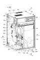
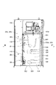
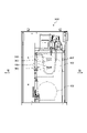
- FIG. 1A shows a schematic diagram of the scroll compressor S1 according to the first embodiment as viewed obliquely from the front and above.
- FIG. 1B shows a schematic diagram of a state in which the side plate 1i1, the front plate 101m, and the front A partition wall 202a (see FIG. 2A) that form the housing 101 of the scroll compressor S1 in Embodiment 1 are removed.
- a casing 101 forms an outer shell of the scroll compressor S1 of the first embodiment.
- the housing 101 has a front plate 101m, a top plate 101t, a rear plate 101u (see FIG. 2B), side plates 1i1 and 1i2, and a bottom plate 101o. Inside the side plate 1i1, an electrical component box 204b containing electrical components 204d (see FIG. 2C) for controlling the scroll compressor S1 is installed.
- the side plate 1i1 is provided with an intake port 101a.
- a scroll compressor main body 102, a motor 103, a control board 104, an air tank 105, an electric fan 106, and an air dryer 107 are installed inside the housing 101 shown in FIG. 1B.
- the scroll compressor main body 102 compresses the air supplied from the suction port 109 .
- Motor 103 drives scroll compressor body 102 .
- the control board 104 controls the operation of the scroll air compressor S1.
- Air tank 105 stores the compressed air generated by scroll compressor body 102 .
- Electric fan 106 cools air tank 105 that stores high-temperature compressed air.
- the air dryer 107 dehumidifies the compressed air stored in the air tank 105 .
- the air dryer 107 is connected to the air tank 105 by a pipe 108 serving as a flow path for compressed air.
- the scroll compressor body 102 has a suction port 109 for sucking air.
- a filter 109f for removing dust in the air is installed on the peripheral surface 109s of the suction port 109 .
- the suction port 109 and the filter 109f are two is mentioned as an example, the number of the suction port 109 and the filter 109f is not restricted to two.
- the number of suction port 109 and filter 109f may be one, or three or more.
- the scroll compressor body 102 and an air tank 105 storing compressed air generated by the scroll compressor body 102 are connected by a rubber hose 110 .
- An exhaust port 101e of the air dryer 107 and an exhaust port 101s of the scroll compressor main body 102 are opened in the top plate 101t of the housing 101. As shown in FIG. The air that has cooled the air dryer 107 is discharged from the exhaust port 101e. The air that has cooled the scroll compressor main body 102 is discharged from the exhaust port 101s.
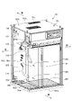
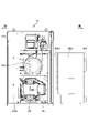
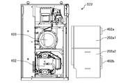
- FIG. 2A shows a schematic diagram of a state in which the front plate 101m and the side plate 101i of the housing 101 of the scroll compressor S1 in Embodiment 1 are removed.
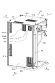
- FIG. 2B shows a schematic diagram of a state in which the front plate 101m and the side plate 101i of the housing 101 of the scroll compressor S1 are removed, as viewed obliquely from the upper left rear.
- FIG. 2C shows a schematic diagram of the state in which the rear plate 101u of the housing 101 of the scroll compressor S1 is removed, as seen from the upper left rear. Note that FIG. 2C shows a state in which the lid of the electrical component box 204b is removed.
- FIG. 2A the interior of the housing 101 is divided into a machine room 201, an A room 203, and a B room 204.
- a front A partition wall 202a and a rear A partition wall 202b are installed to separate the machine room 201 from other spaces, namely, a rear A room 203 and a front B room 204.
- the A partition 202 has a front A partition 202a and a rear A partition 202b.
- the rear A partition wall 202 b is fixed to the housing 101 .
- the front A partition 202a and the rear A partition 202b may be collectively referred to as the A partition 202.
- FIG. 2A the interior of the housing 101 is divided into a machine room 201, an A room 203, and a B room 204.
- a front A partition wall 202a and a rear A partition wall 202b are installed to separate the machine room 201 from other spaces, namely, a rear A room 203 and a front B room 204.
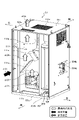
- FIG. 3 shows a schematic view from the right side of the scroll compressor S1 according to Embodiment 1 with the outer plate of the housing 101 and the air tank 105 (see FIG. 2A) removed.
- a handle 402 for a user to hold is installed at the front upper portion of the front A partition wall 202a.
- a B partition wall 205 is installed in the housing 101 to divide the A room 203 and the B room 204, which are spaces other than the machine room 201.
- a scroll compressor body 102 and a motor 103 are installed in the machine room 201 .
- An air tank 105 is arranged in the A chamber 203 .
- An intake port 206 for introducing outside air is formed in the lower rear portion of the A chamber 203 on the rear side.
- the cold air passing through the intake port 206 cools the air tank 105.
- cold air flows from the bottom to the top by generating an air current in the tank chamber of the A chamber 203 with the electric fan 106 .
- it is more effective to dispose the intake port 206 in the lower part.
- an exhaust port 101f is provided on the upper portion of the rear plate 101u of the housing 101 behind the electric fan 106.
- the rear plate 101u of the housing 101 is provided with an air intake port 101h for the scroll compressor body 102 and air intake ports 101d1 and 101d2 for the air dryer 107.
- the scroll compressor main body 102 is cooled by the air entering from the intake port 101h of the rear plate 101u.
- the air dryer 107 is cooled by the air entering from the intake ports 101d1 and 101d2 of the rear plate 101u.
- FIG. 2C the B chamber 204 is provided with an electrical component box 204b for storing an electrical component 204d, an electromagnetic valve (not shown) for drain discharge, and the like.
- an electrical component box 204b for storing an electrical component 204d
- an electromagnetic valve not shown
- various components such as the pipe 108, the rubber hose 110, the electrical component box 204b, and the electromagnetic valve for drain discharge can be accommodated in the B chamber 204, which has a relatively large amount of empty space.
- a front A partition 202a and a rear A partition 202b forming the A partition 202 separate the machine chamber 201 from the rear A chamber 203 and the front B chamber 204.
- the exhaust duct 111 is formed surrounded by the rear A partition wall 202b, the duct side partition wall 111a, the duct upper partition wall 111b, the bottom plate 101o, and the top plate 101t.
- a current plate 111o is installed inside the exhaust duct 111.
- the rectifying plate 111o reduces the speed of the air sent to the exhaust duct 111 to promote heat absorption. The airflow in exhaust duct 111 will be described.
- the rectifying plate 111o is arranged so that the bottom plate 101o of the housing 101 cannot be seen when looking down from the exhaust port 101s, thereby blocking the path of the upward airflow ⁇ 23, thereby reducing noise. also has the effect of In other words, if there is a path through which air flows, vibrations are also transmitted through the air from there. Therefore, the noise can be reduced by preventing the air flow path from being in a straight line.
- the rear A partition wall 202b is provided with a ventilation port 301 (A ventilation port) that is a hole that communicates at least the machine chamber 201 and the A chamber 203 with each other.
- Electric fan 106 (see FIG. 4A) creates an air current in the tank chamber of chamber A 203, so cold air flows from bottom to top. Air vents) are more effective if placed at the bottom.
- the "lower part” includes the lower part of the center, the upstream side of the airflow, and the like.
- the vent 301 is located near the suction port 109 (see FIG. 1B) of the scroll compressor body 102 installed in the machine room 201 . Cold air flows into the scroll compressor body 102 from the vent 301 . Therefore, the scroll compressor main body 102 can be effectively cooled, and efficiency and performance can be improved.
- the front A partition wall 202 a has a vent 302 (B vent) communicating with the B chamber 204 .
- the air inside the B chamber 204 enters the machine chamber 201 through the vent 302 and cools the scroll compressor main body 102 .
- a rubber hose 110 that connects the scroll compressor main body 102 and the air tank 105 passes through the vent 302 . Therefore, the air passing through the vent 302 can cool the rubber hose 110 .
- the front A partition wall 202a has a slit 303 through which the machine room 201 and the B room 204 communicate.
- the slit 303 is different from the vent 301 (A vent) of the rear A partition 202b and the vent 302 (B vent) of the front A partition 202a shown in FIG.
- the slit 303 is installed near the filter 109f of the suction port 109 of the scroll compressor main body 102 . Thereby, cold air can be effectively supplied from the slit 303 to the filter 109f installed in the suction port 109.
- the slit 303 has a rectangular shape with a short vertical dimension and a long horizontal dimension.
- the two slits 303 are positioned above the suction port 109 of the scroll compressor body 102 . This is for blocking the air warmed by the motor 103 installed above the scroll compressor main body 102 by making the air in the B chamber 204 pass through the slit 303 to form a layer.
- Air in the B chamber 204 is supplied to the suction port 109 of the scroll compressor main body 102 through the slit 303 . Thereby, cold air in the B chamber 204 can be supplied to the suction port 109 through the slit 303 .
- two slits 303 are provided below the parallel portion 108h of the pipe 108 to which the air dryer 107 and the air tank 105 are connected, in parallel with the parallel portion 108h, and in the scroll compressor main body 102. It is arranged above the suction port 109 of the. Note that the upper slit 303 is arranged between the lower slit 303 and the motor 103 when viewed from the side. Due to the shape and arrangement of the slit 303, the airflow from the motor 103 and the air from the B chamber 204 can be separated by layered air. Thus, the slit 303 is installed near the pipe 108 and the motor 103 of the air dryer 107 . Thereby, the piping 108 and the motor 103 can be cooled.
- the noise generated in the machine room 201 from the scroll compressor body 102, etc. passes through the front A partition wall 202a and the rear A partition wall 202b, echoes on the inner wall surface of the housing 101 in the A chamber 203 or the B chamber 204, and then travels outside the housing 101. is released to Therefore, it is possible to reduce the noise value of the scroll compressor S1.
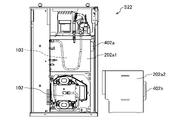
- FIG. 4A shows a schematic diagram of a state in which part of the side plate 1i1 and the front plate 101m of the housing 101 of the scroll compressor S1 in Embodiment 1 are removed.
- FIG. 4B shows a schematic left side view of a state in which the side plate 1i1 of the casing 101 of the scroll compressor S1 of Embodiment 1 is removed and the front A partition wall 202a is removed.
- part of the outside air taken in from the intake port 206 of the rear plate 101u passes through the A chamber 203 and enters the machine chamber 201 through the ventilation port 301 (A ventilation port) of the rear A partition wall 202b. come in.
- the airflow from the A vent 301 branches and flows to the motor 103 side and the suction port 109 .
- the flow path from the A vent 301 to the motor cooling fan (electric fan 106) via the motor 103 is different from the flow path from the A vent 301 to the suction port 109 .
- cold air is supplied to the scroll compressor body 102 through the A vent 301 .
- the suction port 109 is arranged so as to be close to the suction port 206 in terms of the positional relationship with the sirocco fan 103c. For this reason, cold air (air before being warmed by devices such as the motor 103) can be sucked from the suction port 206 through the suction port 109, thereby improving the compression efficiency.
- the air vent 301 of the rear A partition wall 202b shown in FIG. By reducing the intake resistance of the intake port 109 by these measures, it is possible to improve the performance.
- the suction port 109 is located at a position where it can suck in cold air (air before being warmed by devices such as the motor 103) from the ventilation port 301, which contributes to the improvement of compression efficiency. do.
- outside air taken in from around the air dryer 107 on the front upper side of the housing 101 is supplied from the C vent 401 to the B chamber 204 (white arrow ⁇ 11 in FIG. 4A).
- Air supplied from the C vent 401 forms a flow along the pipe 108 and is supplied to the scroll compressor main body 102 through the slit 303 and the vent 302 .
- the pipe 108 is cooled by the airflow indicated by the outline arrow ⁇ 11 in FIG. 4A, thereby reducing the temperature of the compressed air supplied to the air dryer 107 and reducing the load on the air dryer 107.
- a handle 402 is provided on the front A partition wall 202a. During periodic inspection, the user can grasp the handle 402 and pull out the front A partition wall 202a. By providing the handle 402 on the front partition wall A 202a in this way, the handleability when pulling out the front partition wall A 202a is improved.
- the front A partition wall 202a is fixed to the easily accessible front side by bolts b1, fitting, or the like.
- the front A partition wall 202a can be fixed by fitting several bolt fastening points on the front side and the lower projections of the front A partition wall 202a into the notches of the bottom plate 101o.
- the front A partition wall 202a may be fixed without using the bolt b1.
- the upper surface and the rear surface side are pressed against an elastic body 202d (see FIG. 4B) to ensure airtightness, suppress vibration, and improve maintainability.
- the upper elastic body 101d (see FIG. 3) is installed in the housing 101. As shown in FIG.
- a front A partition wall 202a and a rear A partition wall 202b are provided, and as shown in FIG. A partition wall 205 is installed to divide the space other than the machine room 201 into an A room 203 and a B room 204 .
- an intake port 206, a vent port 301, a vent port 302, and the like are provided.
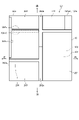
- FIG. 5 shows a schematic arrangement diagram of the scroll compressor S2 of Embodiment 2 as viewed from above.
- the A chamber 203 is arranged on the front side
- the B chamber 204 is arranged on the rear side.
- Other configurations are the same as those of the first embodiment.
- the B chamber 204 having a large internal space volume is arranged on the rear side, it is possible to reduce the depth dimension and reduce the size.
- the exhaust duct 111 shown in FIG. 2C can be enlarged by arranging the B chamber 204 having a large empty volume of the internal space on the rear side. As a result, the cooling performance of the sirocco fan 102c (see FIG. 1B) is improved, thereby improving the performance of the scroll compressor S1.
- a machine room 201 and an exhaust duct 111 are provided on the sides of the A chamber 203 and the B chamber 204 .
- An intake port 206 (also see FIG. 2B) is provided in the lower rear portion of the B chamber 204 of the casing 101 of the scroll compressor S2.
- An air tank 105 is installed in the A chamber 203 .
- An intake port 203 k for cooling the air tank 105 of the A chamber 203 is opened in the lower side of the housing 101 forming the A chamber 203 .
- a scroll compressor body 102 is provided in the lower part of the machine room 201, and a driving motor 103 is provided in the upper part thereof. Therefore, operating noise is generated in the machine room 201 . If the sound absorbing material is attached at a position away from the machine room 201 and at a position where a large surface can be obtained, the effect of soundproofing is large. Therefore, a sound absorbing material 204v is attached to the inner surface of the housing 101 on the side of the B chamber 204 . Moreover, in order to further enhance the soundproof effect, a soundproof partition 204s may be provided. Alternatively, the sound absorbing material 204v0 may be attached to the partition 204s.
- the scroll compressor S2 having a high soundproofing effect.
- the soundproof partition 204s may be provided without providing the sound absorbing material 204v, or only the partition 204s and the sound absorbing material 204v0 may be provided.
- the positional relationship among the machine chamber 201, the A chamber 203, and the B chamber 204 may be changed as in another example below.
- FIG. 6 shows an arrangement schematic diagram of the scroll compressor S21 of another example 1 of the second embodiment as viewed from above.
- the scroll compressor S21 of another example has the same arrangement of the machine chamber 201, the A chamber 203, and the B chamber 204 as the scroll compressor S2 of the second embodiment.
- the partitions 204s1, 204s2, 204s3, and 204s4 for soundproofing are alternately arranged so that the ends thereof partially overlap each other. This will enhance the soundproofing effect.
- Sound absorbing materials 204v1, 204v2, 204v3, and 204v4 may be attached to the soundproof partitions 204s1, 204s2, 204s3, and 204s4, respectively. This further enhances the soundproofing effect.
- the positional relationship between the scroll compressor main body 102 and the motor 103 in the machine chamber 201 may be changed as in Example 2 below.
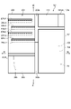
- FIG. 7 shows a schematic diagram of the scroll compressor S22 of Example 2 of Embodiment 2 as viewed from the A chamber 203 and B chamber 204 sides.
- the motor 103 is arranged in the lower part of the machine room 201, and the scroll compressor main body 102 is arranged in the upper part.
- the suction port 109 is positioned in the upper part. Therefore, the two slits 303 are arranged slightly below the suction port 109 on the lower motor 103 side.
- Layered air is sent to the suction port 109 through the slit 303 having a short vertical dimension and a long horizontal dimension to form a so-called air curtain, and the air warmed by cooling the motor 103 below is sucked into the suction port 109. is suppressed.
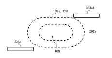
- FIG. 8 shows a schematic view of the slit 303a of the front A partition wall 202a and the suction port 109 of the scroll compressor main body 102 of Modification 1 as seen from the left side.
- the slit 303a of Modification 1 may form a channel by providing a plurality of holes near the filter 109f on the peripheral surface 109s of the suction port 10 .
- the slits 303a of the plurality of holes are formed so that the vertical dimension is short and the horizontal dimension is long.
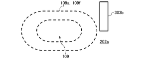
- FIG. 9 shows a schematic view of the slit 303b of the front A partition wall 202a and the suction port 109 of the scroll compressor main body 102 of Modification 2 as viewed from the left side.
- the slit 303b of Modification 2 is a vertically long hole near the filter 109f on the peripheral surface 109s of the suction port 10.
- FIG. That is, the slit 303b is a hole with a short horizontal dimension and a long vertical dimension.
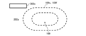
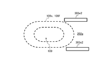
- FIG. 10 shows a schematic view of the slit 303c of the front A partition wall 202a and the suction port 109 of the scroll compressor main body 102 of Modification 3 as viewed from the left side.
- the slit 303c of Modification 3 is a horizontally elongated hole near the filter 109f on the peripheral surface 109s of the suction port 10 . That is, the slit 303c is a hole with a long horizontal dimension and a short vertical dimension.
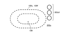
- 11A and 11B are schematic diagrams of the slits 303d1 and 303d2 of the front A partition wall 202a and the suction port 109 of the scroll compressor body 102 of Modification 4 as viewed from the left side.
- the slits 303d1 of Modification 4 shown in FIG. 11A are three round holes near the filter 109f on the peripheral surface 109s of the suction port 10 .
- the circular slit 303d1 is a slit with a long vertical dimension and a short horizontal dimension in all three circular holes.
- a slit 303d2 of Modification 4 shown in FIG. 11B is a hole having a flat curvature near the filter 109f on the peripheral surface 109s of the suction port 10 . As shown in Modification 4, the slit 303 need not be a rectangular hole.
- FIG. Modification 4 is a modification of the positional relationship between the suction port 109 of the scroll compressor body 102 and the slit 303 .
- a slit 303e1 of Modified Example 5 shown in FIG. 12A is formed as a horizontally long slit diagonally near the filter 109f on the peripheral surface 109s of the suction port 10 .
- Slits 303e2 of modification 5 shown in FIG. 12B are formed by forming two oblong slits on one side of peripheral surface 109s of suction port 10 near filter 109f. According to Modifications 1 to 5 described above, it is possible to suck in unheated air from the suction port 109 of the scroll compressor main body 102 while blocking warmed air that has cooled the motor 103 .
- FIG. 13A shows a scroll compressor s22 with the front A first partition wall 202a1 and the front A second partition wall 202a2 removed in Modification 6, viewed from the B chamber 204 and A chamber 203 sides.
- FIG. 13B shows a view of the scroll compressor s22 with the front A first partition wall 202a1 removed and the front A second partition wall 202a2 removed, viewed from the B chamber 204 and A chamber 203 sides in Modification 6. show.
- Modification 6 has a configuration in which the front A partition wall 202a described in the embodiment is divided into two A first partition wall 202a1 and a front A second partition wall 202a2.
- the front A partition wall 202a of Modification 6 includes a front A first partition wall 202a1 that partitions the machine room 201 on the motor 103 side, and a front A second partition wall 202a2 that partitions the scroll compressor body 102 side of the machine room 201. have.
- the front A first partition wall 202a1 and the front A second partition wall 202a2 are freely attachable and detachable.
- a grip handle 402a is attached to the front A first partition 202a1.
- the front A second partition wall 202a2 is provided with a handle 402b for grasping.
- the user can remove and attach the front A first partition 202a1 and the front A second partition 202a2 by gripping the handles 402a and 402b, respectively. Further, as shown in FIG. 13B, the user can also pull out only the front A second partition wall 202a2 without pulling out the front A first partition wall 202a1 by gripping the handle 402b. Although not shown, only the front A first partition wall 202a1 can be removed and attached by gripping the handle 402b. According to Modification 6, the scroll compressor S22 is easier to handle.
- the A partition is composed of the front A partition 202a and the rear A partition 202b.
- the entire A partition may be configured to be removable with a handle 402 (see FIG. 3). As a result, the user can grasp the handle 402 and take out and attach the entire A partition, improving maintainability and handling.
- the present invention is not limited to the above-described embodiments, modifications, and the like, and includes various modifications.
- the above-described embodiments, modifications, and the like have been described in detail in order to explain the present invention in an easy-to-understand manner, and are not necessarily limited to those having all the described configurations.
- the compressor main body can be replaced with a screw compressor, a reciprocating compressor, or the like other than the scroll compressor.
- any gas other than air such as hydrogen gas, nitrogen gas, or Freon gas, by arranging the entire package in a space filled with a specific gas.
Landscapes
- Engineering & Computer Science (AREA)
- Mechanical Engineering (AREA)
- General Engineering & Computer Science (AREA)
- Applications Or Details Of Rotary Compressors (AREA)
- Compressors, Vaccum Pumps And Other Relevant Systems (AREA)
Abstract
Description
特許文献1には、電動モータ(9)を駆動するインバータ装置(11)の冷却手段として、インバータ装置専用の冷却風ダクト(12)とそのダクト(12)内に専用の冷却ファン(10)を設けることで、インバータ装置(11)を冷却ファン(10)により冷却すると共に、冷却後の空気を外部に排気して圧縮部(8)、電動モータ(9)等の冷却効率も高めることができる圧縮機が記載されている。
本発明は上記実状に鑑み創案されたものであり、騒音低減と吸気温度の低減を両立させる圧縮機の提供を目的とする。
<<実施形態1>>
図1Bに、実施形態1におけるスクロール式圧縮機S1の筐体101を形成する側板1i1、前板101mおよび前A隔壁202a(図2A参照)を取り外した状態の模式図を示す。
筐体101は、前板101m、天板101t、後板101u(図2B参照)、側板1i1、1i2、および底板101oを有している。側板1i1の内側には、スクロール式圧縮機S1の制御を担う電気部品204d(図2C参照)が収納された電気品箱204bが設置されている。側板1i1には、吸気口101aが設けられている。
スクロール圧縮機本体102は、吸込み口109から供給される空気の圧縮を行う。モータ103は、スクロール圧縮機本体102を駆動する。
制御基板104は、スクロール式空気圧縮機S1の運転を制御する。空気タンク105は、スクロール圧縮機本体102で生成した圧縮空気を貯留する。
スクロール圧縮機本体102は、空気を吸い込むための吸い込み口109を有する。吸込み口109はその周面109sに、空気中の塵埃を除去するためのフィルタ109fが設置されている。なお、本実施形態では、吸い込み口109とフィルタ109fを2つの場合を例に挙げているが、吸い込み口109とフィルタ109fの数は2つに限らない。例えば、吸い込み口109、フィルタ109fは1つでもよいし、3つ以上としてもよい。
筐体101の天板101tには、エアードライヤー107の排気口101eとスクロール圧縮機本体102の排気口101sが開口されている。
排気口101eからは、エアードライヤー107を冷却した空気が排出される。排気口101sからは、スクロール圧縮機本体102を冷却した空気が排出される。
図2Bに、スクロール式圧縮機S1の筐体101の前板101mと側板101iを取り外した状態を左斜め上後方から見た模式図を示す。
図2Aに示すように、筐体101の内部は、機械室201とA室203とB室204とに区分けされている。
筐体101内には、機械室201とそれ以外の空間である後側のA室203、前側のB室204とを区切る前A隔壁202aと後A隔壁202b(図3参照)が設置されている。
A隔壁202は、前A隔壁202aと後A隔壁202bとを有する。後A隔壁202bは、筐体101に固定されている。
なお、前A隔壁202aと後ろA隔壁202bを総称して、A隔壁202と称することがある。
図3に、実施形態1におけるスクロール式圧縮機S1の筐体101の外部板と空気タンク105(図2A参照)とを取り外した状態を右側から見た模式図を示す。
前A隔壁202aの手前上部には、利用者が把持するための把手402が設置されている。
機械室201には、スクロール圧縮機本体102およびモータ103が設置されている。
A室203には、空気タンク105が配置されている。
後側のA室203の後下部には、外気を導入する吸気口206が形成されている。吸気口206を空気タンク105の下部後方に配置することで、吸気口206を通過した冷たい空気で空気タンク105を冷却する。
図4Aに示すように、A室203のタンク室内に電動ファン106によって気流を起こすことで、下から上に冷たい空気が流れる。また、冷たい空気が下の方に溜まり易いことから、吸気口206は下部に配置した方が効果が高い。
これにより、後板101uの吸気口101hから入る空気でスクロール圧縮機本体102を冷却している。後板101uの吸気口101d1、101d2から入る空気でエアードライヤー107を冷却する。
図1Bに示す前側のB室204には、エアードライヤー107と空気タンク105とが接続される配管108と、スクロール圧縮機本体102と空気タンク105とが接続されるゴムホース110が設置されている。図2Cに示すように、B室204には電気部品204dを格納する電気品箱204b、ドレン排出用の電磁弁(図示しない)等が設置されている。こうして、比較的空きスペースが多いB室204に配管108、ゴムホース110、電気品箱204b、ドレン排出用の電磁弁等の各種構成要素を収容することができる。
<排気ダクト111>
排気ダクト111の内部には、整流板111oが設置されている。整流板111oは、排気ダクト111に送られる空気の速度を落として吸熱を促進する。
排気ダクト111の空気流れについて説明する。
さらに、整流板111oは、排気口101sから下方向を覗き込んだ際に、筐体101の底板101oを目視できないように配置することで、上昇気流α23が通る経路を遮ることができ、騒音低減の効果もある。つまり、空気が流れる経路がある、ということはそこから振動も空気を伝わって伝達される。そこで、空気流路が一直線にならないようにすることで騒音を軽減できる。
図3に示すように、後A隔壁202bには、少なくとも機械室201とA室203とを連通する穴である通気口301(A通気口)が設けられている。A室203のタンク室内に電動ファン106(図4A参照)によって気流を起こすことで、下から上に冷たい空気が流れる、また、冷たい空気が下の方へ溜まり易いことから、通気口301(A通気口)は下部に配置した方が効果が高い。なお、「下部」とは、中央より下、気流の上流側等を含む。
通気口301は、機械室201に設置されるスクロール圧縮機本体102の吸込み口109(図1B参照)の近傍に位置している。通気口301から冷たい空気がスクロール圧縮機本体102に流れる。そのため、スクロール圧縮機本体102を効果的に冷却でき、効率を向上し性能を上げることができる。
前A隔壁202aは、B室204に連通する通気口302(B通気口)を有する。B室204の内部の空気は、通気口302を通って機械室201に入り、スクロール圧縮機本体102を冷却する。
前A隔壁202aは、機械室201とB室204とが連通するスリット303を有する。スリット303は、図3に示す後A隔壁202bの通気口301(A通気口)および前A隔壁202aの通気口302(B通気口)とは異なるものである。スリット303は、スクロール圧縮機本体102の吸込み口109のフィルタ109f近くに設置されている。これにより、スリット303から吸込み口109に設置されるフィルタ109fに冷たい空気を効果的に供給できる。即ち、スクロール圧縮機本体109は、フィルタ109fを介して吸込み口109から冷たい空気(モータ103等の機器で暖められる前の空気)を取り入れることができるので、圧縮効率も向上し性能を上げることができる。
スリット303の形状と配置により、層状の空気でモータ103からの気流と、B室204からの空気とを分けることができる。こうして、スリット303をエアードライヤー107の配管108とモータ103の近くに設置している。これにより、配管108とモータ103とを冷却できる。
図4Bに、実施形態1のスクロール式圧縮機S1の筐体101の側板1i1を取り外し、前A隔壁202aを外した状態を左側から見た模式図を示す。
後板101uの吸気口206から取り込まれた外気の一部は、図3に示すように、A室203を通過して、後A隔壁202bの通気口301(A通気口)から機械室201に入る。
A通気口301からの気流は分岐してモータ103の側と吸い込み口109とへ流れる。具体的には、A通気口301からモータ103を介してモータ冷却ファン(電動ファン106)への流路と、A通気口301から吸い込み口109への流路が異なる。こうして、A通気口301を通して、冷たい空気がスクロール圧縮機本体102に供給される。
つまり、吸込み口109は、シロッコファン103cとの位置関係で、吸気口206に近くなるよう配置されている。このため、吸込み口109からは吸気口206からの冷たい空気(モータ103等の機器で暖められる前の空気)を吸い込むことができ、圧縮効率が向上する。
本実施形態1では、図4Bに示すように、前A隔壁202aに把手402を設けている。定期点検時には、利用者が把手402を把持して前A隔壁202aを手前に引き出せる。このように、前A隔壁202aに把手402を設けることで、前A隔壁202aを手前に引き出す際の取扱い性を向上している。
前A隔壁202aは、固定に際して、上面と背面側は弾性体202d(図4B参照)を押し当てることで気密性の確保、振動の抑制、メンテナンス性の向上を図っている。なお、上面側の弾性体101d(図3参照)は筐体101に設置されている。
これにより、騒音低減と吸気温度の低下を両立させるスクロール式圧縮機を実現できる。
<<実施形態2>>
実施形態2のスクロール式圧縮機S2は、A室203を前側に配置し、B室204を後側に配置したものである。
その他の構成は、実施形態1と同じである。
これにより、内部空間の容積が大きいB室204を後側に配置するので、奥行寸法を削り小型化が可能となる。
スクロール式圧縮機S2の筐体101のB室204の後下部には吸気口206(図2Bを併せて参照)が設けられている。
A室203には、空気タンク105が設置されている。A室203を形成する筐体101の側下部には、A室203の空気タンク105を冷却するための吸気口203kが開口されている。
機械室201から離れた位置かつ、面が大きく取れる位置に吸音材を貼ると防音の効果が大きい。そこで、B室204の側方の筐体101の内面に吸音材204vを貼り付けている。
また、さらに防音効果を高めるために、防音用の仕切り204sを設けてもよい。または、仕切り204sに吸音材204v0を貼り付けてもよい。
なお、吸音材204vを設けることなく、防音用の仕切り204sのみを設けてもよいし、或いは、仕切り204sと吸音材204v0のみを設けてもよい。
なお、実施形態1と同様のスクロール式圧縮機S1において、下記の他例のように、機械室201、A室203、B室204の位置関係を変更してもよい。
図6に、実施形態2の他例1のスクロール式圧縮機S21を上方から見た配置模式図を示す。
他例のスクロール式圧縮機S21は、実施形態2のスクロール式圧縮機S2と機械室201、A室203、B室204の配置は同じである。
そして、防音用の仕切り204s1、204s2、204s3、204s4を互い違いに先端側の一部が重なるように配置している。これにより、防音効果を高められる。
なお、実施形態1のスクロール式圧縮機S1において、下記の他例2のように、機械室201内のスクロール圧縮機本体102とモータ103の位置関係を変更してもよい。
図7に、実施形態2の他例2のスクロール式圧縮機S22をA室203、B室204の側から見た模式図を示す。
他例2のスクロール式圧縮機S22は、機械室201においてモータ103を下部に配置し、スクロール圧縮機本体102を上部に配置している。
この場合、スクロール圧縮機本体102が上部に配置されるので、吸込み口109が上部に位置する。そのため、2つのスリット303はそれぞれ下部のモータ103側の吸込み口109のやや下方に配置される。縦寸法が短く横寸法が長いスリット303により層状の空気を吸込み口109に送ることで言わば空気のカーテンを形成し、下部のモータ103を冷却して温められた空気が吸込み口109に吸い込まれることを抑制している。
実施形態1のスクロール式圧縮機S1において、例えば通気口301(図3参照)、スリット303(図2A参照)の面積を増加させることで、スクロール圧縮機本体102の吸込み口109(図1B参照)へ供給する空気量が増加し、性能の向上が可能となる。
実施形態1と同一の構成については同一の符号を付し、その説明を省略する。
変形例では、実施形態1のスクロール圧縮機本体102の吸込み口109に対するスリット303の変形例を示す。
下記図8~図12Bに示すスクロール圧縮機本体102の吸込み口109はその周面109sにフィルタ109fが設置されている。
変形例1のスリット303aは、吸込み口10の周面109sのフィルタ109f近くに複数の穴を設けることで流路を形成してもよい。複数の穴のスリット303aは、全体として、縦寸法が短く横寸法が長く形成されている。
図9に、変形例2の前A隔壁202aのスリット303bとスクロール圧縮機本体102の吸込み口109とを左側方から見た模式図を示す。
変形例2のスリット303bは、吸込み口10の周面109sのフィルタ109f近くに縦長の穴とした場合である。つまり、スリット303bは横寸法が短く縦寸法が長い穴である。
図10に、変形例3の前A隔壁202aのスリット303cとスクロール圧縮機本体102の吸込み口109とを左側方から見た模式図を示す。
変形例3のスリット303cは、吸込み口10の周面109sのフィルタ109f近くに横長の穴としている。つまり、スリット303cは横寸法が長く縦寸法が短い穴である。
図11A、図11Bに、変形例4の前A隔壁202aのスリット303d1、303d2とスクロール圧縮機本体102の吸込み口109とを左側方から見た模式図を示す。
変形例4に示すように、スリット303は矩形の穴である必要はない。
図12A、図12Bに、変形例5の前A隔壁202aのスリット303e1、303e2とスクロール圧縮機本体102の吸込み口109とを側方から見た模式図を示す。
変形例4は、スクロール圧縮機本体102の吸込み口109とスリット303の位置関係の変形例である。
図12Bに示す変形例5のスリット303e2は、吸込み口10の周面109sのフィルタ109f近くの一方側に横長のスリットを2つ形成したものである。
上述の変形例1~5によっても、モータ103を冷却した温まった空気を遮りつつ、加温されてない空気をスクロール圧縮機本体102の吸込み口109から吸い込むことができる。
図13Aに、変形例6の前A第1隔壁202a1と前A第2隔壁202a2とを取り外した状態のスクロール式圧縮機s22を、B室204、A室203の側から見た図を示す。
図13Bに、変形例6の前A第1隔壁202a1を取り外さず、前A第2隔壁202a2を取り外した状態のスクロール式圧縮機s22を、B室204、A室203の側から見た図を示す。
変形例6の前A隔壁202aは、機械室201のモータ103の側を隔壁する前A第1隔壁202a1と、機械室201のスクロール圧縮機本体102の側を隔壁する前A第2隔壁202a2とを有している。
前A第1隔壁202a1と前A第2隔壁202a2とは、取り付け、取り外し自在である。
前A第1隔壁202a1には、把持用の把手402aが付いている。
前A第2隔壁202a2には、把持用の把手402bが付いている。
また、利用者は、図13Bに示すように、前A第1隔壁202a1は引き出さず、前A第2隔壁202a2のみを把手402bを把持して、引き出すこともできる。図示しないが、前A第1隔壁202a1のみを、把手402bを把持して、取り外し、取り付けできる。
変形例6によれば、スクロール式圧縮機S22の取り扱い性が向上する。
1.前記実施形態では、A隔壁を前A隔壁202aと後A隔壁202bとで構成し、後A隔壁202bを筐体101への固定構造とするとともに前A隔壁202aに把手402(図3参照)を付けて取り出し可能としたが、A隔壁全体を把手402(図3参照)を付けた取り出し可能な構成としてもよい。これにより、利用者は、把手402を把持してA隔壁全体を取り出し取り付けでき、メンテナンス性、取り扱い性が向上する
或いは、パッケージ全体を特定気体で満たされた空間に配置するなどして、空気以外の気体の水素ガス、窒素ガス、フロンガス等の任意のガスを圧縮することも可能である。
102 スクロール圧縮機本体(圧縮機本体)
103 モータ
104 制御基板
105 空気タンク(タンク)
106 電動ファン(冷却ファン)
107 エアードライヤー
108 配管
109 吸込み口
109f フィルタ
110 ゴムホース
201 機械室
202 A隔壁
202a 前A隔壁(A隔壁)
202b 後A隔壁(A隔壁)
203 A室
204 B室
204d 電気部品
205 B隔壁
206 吸気口
301 A通気口(連通する穴)
302 B通気口
303 スリット
401 C通気口
402 把手
S1、S2、S21 圧縮機(スクロール式圧縮機)
Claims (9)
- 外郭を形成する筐体と、気体を圧縮する圧縮機本体と、前記圧縮機本体を駆動するモータと、前記モータを制御する制御基板と、前記圧縮機本体からの吐出気体を貯留するタンクとを備え、
前記筐体内には、前記圧縮機本体および前記モータを格納する機械室と、前記圧縮機本体と前記タンクとを接続する配管が配設されるB室と、前記タンクを格納するA室と、前記機械室と前記A室および前記B室とを区切るA隔壁と、前記A室と前記B室とに分割するB隔壁とを有し、
前記A室は、外気を導入する吸気口を有し、
前記A隔壁は、前記機械室と前記A室とを連通する穴であるA通気口を有し、
前記A通気口の近傍に、前記圧縮機本体の吸込み口が位置している圧縮機。 - 請求項1に記載の圧縮機において、
前記A通気口から前記モータの冷却ファンへの流路と、前記A通気口から前記吸込み口への流路とが異なるように構成されている圧縮機。 - 請求項1に記載の圧縮機において、
前記A隔壁は、B室と連通するB通気口と、前記機械室と前記B室とを連通するスリットとを有し、
前記スリットは、前記圧縮機本体の吸込み口近傍に位置している圧縮機。 - 請求項1に記載の圧縮機において、
前記A隔壁は、B室と連通するB通気口と、前記機械室と前記B室とを連通するスリットとを有し、
前記スリットは、前記圧縮機本体の吸込み口近傍に位置し、
前記スリットは、前記配管に沿った流れを吸い込むことができる位置であって、前記吸込み口のフィルタに近い位置である圧縮機。 - 請求項1に記載の圧縮機において、
前記A隔壁は、B室と連通するB通気口と、前記機械室と前記B室とを連通するスリットとを有し、
前記スリットは、前記圧縮機本体の吸込み口近傍に位置し、
前記スリットは、縦寸法と横寸法とが異なる形状である圧縮機。 - 請求項1に記載の圧縮機において、
前記A隔壁は、B室と連通するB通気口と、前記機械室と前記B室とを連通するスリットとを有し、
前記スリットは、前記圧縮機本体の吸込み口近傍に位置し、
前記スリットは、一つの前記吸込み口に対して複数ある圧縮機。 - 請求項1に記載の圧縮機において、
前記A隔壁は、B室と連通するB通気口と、前記機械室と前記B室とを連通するスリットとを有し、
前記スリットは、前記圧縮機本体の吸込み口近傍に位置し、
前記スリットは、側方から見て前記吸込み口と前記モータとの間にある圧縮機。 - 請求項1に記載の圧縮機おいて、
前記B室には、前記圧縮機本体と前記タンクとが接続されるゴムホースと、制御用の電気部品とが格納されている圧縮機。 - 請求項1に記載の圧縮機おいて、
前記A隔壁の一部または全部が取り外し可能であり、前記A隔壁の取り外しできる部分に把手を有している圧縮機。
Priority Applications (4)
| Application Number | Priority Date | Filing Date | Title |
|---|---|---|---|
| KR1020237026279A KR20230125067A (ko) | 2021-04-27 | 2022-02-07 | 압축기 |
| CN202280011624.6A CN116802399A (zh) | 2021-04-27 | 2022-02-07 | 压缩机 |
| EP22795212.4A EP4332377A1 (en) | 2021-04-27 | 2022-02-07 | Compressor |
| US18/273,406 US20240093687A1 (en) | 2021-04-27 | 2022-02-07 | Compressor |
Applications Claiming Priority (2)
| Application Number | Priority Date | Filing Date | Title |
|---|---|---|---|
| JP2021075302A JP2022169330A (ja) | 2021-04-27 | 2021-04-27 | 圧縮機 |
| JP2021-075302 | 2021-04-27 |
Publications (1)
| Publication Number | Publication Date |
|---|---|
| WO2022230289A1 true WO2022230289A1 (ja) | 2022-11-03 |
Family
ID=83848274
Family Applications (1)
| Application Number | Title | Priority Date | Filing Date |
|---|---|---|---|
| PCT/JP2022/004709 WO2022230289A1 (ja) | 2021-04-27 | 2022-02-07 | 圧縮機 |
Country Status (6)
| Country | Link |
|---|---|
| US (1) | US20240093687A1 (ja) |
| EP (1) | EP4332377A1 (ja) |
| JP (1) | JP2022169330A (ja) |
| KR (1) | KR20230125067A (ja) |
| CN (1) | CN116802399A (ja) |
| WO (1) | WO2022230289A1 (ja) |
Families Citing this family (1)
| Publication number | Priority date | Publication date | Assignee | Title |
|---|---|---|---|---|
| JP7580165B1 (ja) | 2024-06-27 | 2024-11-11 | 章博 隆志 | コンプレッサー用ハウジング |
Citations (6)
| Publication number | Priority date | Publication date | Assignee | Title |
|---|---|---|---|---|
| JPS58161183U (ja) * | 1982-04-21 | 1983-10-27 | トキコ株式会社 | 圧縮機 |
| JP2003240266A (ja) * | 2002-02-20 | 2003-08-27 | Fujitsu General Ltd | 除湿機 |
| JP2004324615A (ja) | 2003-04-28 | 2004-11-18 | Tokico Ltd | パッケージ型圧縮機 |
| JP2007270665A (ja) * | 2006-03-30 | 2007-10-18 | Hitachi Ltd | パッケージ型圧縮機 |
| JP2013144928A (ja) * | 2012-01-13 | 2013-07-25 | Hitachi Industrial Equipment Systems Co Ltd | パッケージ型圧縮機 |
| JP2016075159A (ja) | 2014-10-02 | 2016-05-12 | 株式会社日立産機システム | パッケージ型圧縮機 |
-
2021
- 2021-04-27 JP JP2021075302A patent/JP2022169330A/ja active Pending
-
2022
- 2022-02-07 CN CN202280011624.6A patent/CN116802399A/zh active Pending
- 2022-02-07 US US18/273,406 patent/US20240093687A1/en active Pending
- 2022-02-07 EP EP22795212.4A patent/EP4332377A1/en active Pending
- 2022-02-07 KR KR1020237026279A patent/KR20230125067A/ko not_active Application Discontinuation
- 2022-02-07 WO PCT/JP2022/004709 patent/WO2022230289A1/ja active Application Filing
Patent Citations (6)
| Publication number | Priority date | Publication date | Assignee | Title |
|---|---|---|---|---|
| JPS58161183U (ja) * | 1982-04-21 | 1983-10-27 | トキコ株式会社 | 圧縮機 |
| JP2003240266A (ja) * | 2002-02-20 | 2003-08-27 | Fujitsu General Ltd | 除湿機 |
| JP2004324615A (ja) | 2003-04-28 | 2004-11-18 | Tokico Ltd | パッケージ型圧縮機 |
| JP2007270665A (ja) * | 2006-03-30 | 2007-10-18 | Hitachi Ltd | パッケージ型圧縮機 |
| JP2013144928A (ja) * | 2012-01-13 | 2013-07-25 | Hitachi Industrial Equipment Systems Co Ltd | パッケージ型圧縮機 |
| JP2016075159A (ja) | 2014-10-02 | 2016-05-12 | 株式会社日立産機システム | パッケージ型圧縮機 |
Also Published As
| Publication number | Publication date |
|---|---|
| US20240093687A1 (en) | 2024-03-21 |
| JP2022169330A (ja) | 2022-11-09 |
| EP4332377A1 (en) | 2024-03-06 |
| KR20230125067A (ko) | 2023-08-28 |
| CN116802399A (zh) | 2023-09-22 |
Similar Documents
| Publication | Publication Date | Title |
|---|---|---|
| JP2716934B2 (ja) | パッケージ形油冷式空気圧縮機 | |
| US10227981B2 (en) | Package type fluid machine | |
| US10895155B2 (en) | Package type compressor | |
| JP5850167B2 (ja) | 調湿装置 | |
| WO2012100376A1 (zh) | 引擎发电机 | |
| JP6254052B2 (ja) | エンジンシステム | |
| WO2022230289A1 (ja) | 圧縮機 | |
| KR100837143B1 (ko) | 패키지형 압축기 | |
| JP4255765B2 (ja) | パッケージ形圧縮機 | |
| JP5728738B2 (ja) | パッケージ型の回転ポンプユニット | |
| CN109653986B (zh) | 移动式压缩空气供给机 | |
| JP2007040289A (ja) | パッケージ型圧縮機 | |
| JP4860790B2 (ja) | パッケージ型圧縮機 | |
| JP6078805B2 (ja) | パッケージ型回転ポンプユニットの冷却構造 | |
| JP2006112353A (ja) | パッケージ型圧縮機 | |
| JP4861524B1 (ja) | パッケージ型の回転ポンプユニット | |
| JP4302999B2 (ja) | パッケージ型圧縮機 | |
| JP2007064120A (ja) | パッケージ型圧縮機 | |
| JP2020180591A (ja) | ブロワ及びブロワ用筐体 | |
| WO2020262190A1 (ja) | パッケージ型圧縮機 | |
| JPH03175166A (ja) | 空冷式パツケージ形スクリユー圧縮機 | |
| JP2012026307A (ja) | パッケージ型圧縮機 | |
| JPH07103145A (ja) | パッケージ型圧縮機 | |
| JP2008267206A (ja) | パッケージ形コンプレッサ | |
| JP2006316713A (ja) | エンジン駆動作業装置 |
Legal Events
| Date | Code | Title | Description |
|---|---|---|---|
| 121 | Ep: the epo has been informed by wipo that ep was designated in this application |
Ref document number: 22795212 Country of ref document: EP Kind code of ref document: A1 |
|
| WWE | Wipo information: entry into national phase |
Ref document number: 18273406 Country of ref document: US |
|
| WWE | Wipo information: entry into national phase |
Ref document number: 202317049802 Country of ref document: IN |
|
| WWE | Wipo information: entry into national phase |
Ref document number: 202280011624.6 Country of ref document: CN |
|
| ENP | Entry into the national phase |
Ref document number: 20237026279 Country of ref document: KR Kind code of ref document: A |
|
| WWE | Wipo information: entry into national phase |
Ref document number: 1020237026279 Country of ref document: KR |
|
| WWE | Wipo information: entry into national phase |
Ref document number: 2022795212 Country of ref document: EP |
|
| NENP | Non-entry into the national phase |
Ref country code: DE |
|
| ENP | Entry into the national phase |
Ref document number: 2022795212 Country of ref document: EP Effective date: 20231127 |