WO2022224559A1 - モータ制御装置およびモータ制御方法 - Google Patents
モータ制御装置およびモータ制御方法 Download PDFInfo
- Publication number
- WO2022224559A1 WO2022224559A1 PCT/JP2022/005905 JP2022005905W WO2022224559A1 WO 2022224559 A1 WO2022224559 A1 WO 2022224559A1 JP 2022005905 W JP2022005905 W JP 2022005905W WO 2022224559 A1 WO2022224559 A1 WO 2022224559A1
- Authority
- WO
- WIPO (PCT)
- Prior art keywords
- current
- motor
- phase angle
- control device
- inverter
- Prior art date
- Legal status (The legal status is an assumption and is not a legal conclusion. Google has not performed a legal analysis and makes no representation as to the accuracy of the status listed.)
- Ceased
Links
Images


Classifications
-
- H—ELECTRICITY
- H02—GENERATION; CONVERSION OR DISTRIBUTION OF ELECTRIC POWER
- H02P—CONTROL OR REGULATION OF ELECTRIC MOTORS, ELECTRIC GENERATORS OR DYNAMO-ELECTRIC CONVERTERS; CONTROLLING TRANSFORMERS, REACTORS OR CHOKE COILS
- H02P21/00—Arrangements or methods for the control of electric machines by vector control, e.g. by control of field orientation
- H02P21/05—Arrangements or methods for the control of electric machines by vector control, e.g. by control of field orientation specially adapted for damping motor oscillations, e.g. for reducing hunting
-
- B—PERFORMING OPERATIONS; TRANSPORTING
- B60—VEHICLES IN GENERAL
- B60L—PROPULSION OF ELECTRICALLY-PROPELLED VEHICLES; SUPPLYING ELECTRIC POWER FOR AUXILIARY EQUIPMENT OF ELECTRICALLY-PROPELLED VEHICLES; ELECTRODYNAMIC BRAKE SYSTEMS FOR VEHICLES IN GENERAL; MAGNETIC SUSPENSION OR LEVITATION FOR VEHICLES; MONITORING OPERATING VARIABLES OF ELECTRICALLY-PROPELLED VEHICLES; ELECTRIC SAFETY DEVICES FOR ELECTRICALLY-PROPELLED VEHICLES
- B60L15/00—Methods, circuits, or devices for controlling the traction-motor speed of electrically-propelled vehicles
- B60L15/007—Physical arrangements or structures of drive train converters specially adapted for the propulsion motors of electric vehicles
-
- B—PERFORMING OPERATIONS; TRANSPORTING
- B60—VEHICLES IN GENERAL
- B60L—PROPULSION OF ELECTRICALLY-PROPELLED VEHICLES; SUPPLYING ELECTRIC POWER FOR AUXILIARY EQUIPMENT OF ELECTRICALLY-PROPELLED VEHICLES; ELECTRODYNAMIC BRAKE SYSTEMS FOR VEHICLES IN GENERAL; MAGNETIC SUSPENSION OR LEVITATION FOR VEHICLES; MONITORING OPERATING VARIABLES OF ELECTRICALLY-PROPELLED VEHICLES; ELECTRIC SAFETY DEVICES FOR ELECTRICALLY-PROPELLED VEHICLES
- B60L15/00—Methods, circuits, or devices for controlling the traction-motor speed of electrically-propelled vehicles
- B60L15/20—Methods, circuits, or devices for controlling the traction-motor speed of electrically-propelled vehicles for control of the vehicle or its driving motor to achieve a desired performance, e.g. speed, torque, programmed variation of speed
- B60L15/2072—Methods, circuits, or devices for controlling the traction-motor speed of electrically-propelled vehicles for control of the vehicle or its driving motor to achieve a desired performance, e.g. speed, torque, programmed variation of speed for drive off
- B60L15/2081—Methods, circuits, or devices for controlling the traction-motor speed of electrically-propelled vehicles for control of the vehicle or its driving motor to achieve a desired performance, e.g. speed, torque, programmed variation of speed for drive off for drive off on a slope
-
- H—ELECTRICITY
- H02—GENERATION; CONVERSION OR DISTRIBUTION OF ELECTRIC POWER
- H02P—CONTROL OR REGULATION OF ELECTRIC MOTORS, ELECTRIC GENERATORS OR DYNAMO-ELECTRIC CONVERTERS; CONTROLLING TRANSFORMERS, REACTORS OR CHOKE COILS
- H02P21/00—Arrangements or methods for the control of electric machines by vector control, e.g. by control of field orientation
- H02P21/14—Estimation or adaptation of machine parameters, e.g. flux, current or voltage
-
- H—ELECTRICITY
- H02—GENERATION; CONVERSION OR DISTRIBUTION OF ELECTRIC POWER
- H02P—CONTROL OR REGULATION OF ELECTRIC MOTORS, ELECTRIC GENERATORS OR DYNAMO-ELECTRIC CONVERTERS; CONTROLLING TRANSFORMERS, REACTORS OR CHOKE COILS
- H02P23/00—Arrangements or methods for the control of AC motors characterised by a control method other than vector control
- H02P23/04—Arrangements or methods for the control of AC motors characterised by a control method other than vector control specially adapted for damping motor oscillations, e.g. for reducing hunting
-
- H—ELECTRICITY
- H02—GENERATION; CONVERSION OR DISTRIBUTION OF ELECTRIC POWER
- H02P—CONTROL OR REGULATION OF ELECTRIC MOTORS, ELECTRIC GENERATORS OR DYNAMO-ELECTRIC CONVERTERS; CONTROLLING TRANSFORMERS, REACTORS OR CHOKE COILS
- H02P27/00—Arrangements or methods for the control of AC motors characterised by the kind of supply voltage
- H02P27/04—Arrangements or methods for the control of AC motors characterised by the kind of supply voltage using variable-frequency supply voltage, e.g. inverter or converter supply voltage
- H02P27/06—Arrangements or methods for the control of AC motors characterised by the kind of supply voltage using variable-frequency supply voltage, e.g. inverter or converter supply voltage using DC to AC converters or inverters
-
- H—ELECTRICITY
- H02—GENERATION; CONVERSION OR DISTRIBUTION OF ELECTRIC POWER
- H02P—CONTROL OR REGULATION OF ELECTRIC MOTORS, ELECTRIC GENERATORS OR DYNAMO-ELECTRIC CONVERTERS; CONTROLLING TRANSFORMERS, REACTORS OR CHOKE COILS
- H02P6/00—Arrangements for controlling synchronous motors or other dynamo-electric motors using electronic commutation dependent on the rotor position; Electronic commutators therefor
- H02P6/28—Arrangements for controlling current
-
- B—PERFORMING OPERATIONS; TRANSPORTING
- B60—VEHICLES IN GENERAL
- B60L—PROPULSION OF ELECTRICALLY-PROPELLED VEHICLES; SUPPLYING ELECTRIC POWER FOR AUXILIARY EQUIPMENT OF ELECTRICALLY-PROPELLED VEHICLES; ELECTRODYNAMIC BRAKE SYSTEMS FOR VEHICLES IN GENERAL; MAGNETIC SUSPENSION OR LEVITATION FOR VEHICLES; MONITORING OPERATING VARIABLES OF ELECTRICALLY-PROPELLED VEHICLES; ELECTRIC SAFETY DEVICES FOR ELECTRICALLY-PROPELLED VEHICLES
- B60L2210/00—Converter types
- B60L2210/40—DC to AC converters
- B60L2210/42—Voltage source inverters
-
- B—PERFORMING OPERATIONS; TRANSPORTING
- B60—VEHICLES IN GENERAL
- B60L—PROPULSION OF ELECTRICALLY-PROPELLED VEHICLES; SUPPLYING ELECTRIC POWER FOR AUXILIARY EQUIPMENT OF ELECTRICALLY-PROPELLED VEHICLES; ELECTRODYNAMIC BRAKE SYSTEMS FOR VEHICLES IN GENERAL; MAGNETIC SUSPENSION OR LEVITATION FOR VEHICLES; MONITORING OPERATING VARIABLES OF ELECTRICALLY-PROPELLED VEHICLES; ELECTRIC SAFETY DEVICES FOR ELECTRICALLY-PROPELLED VEHICLES
- B60L2240/00—Control parameters of input or output; Target parameters
- B60L2240/40—Drive Train control parameters
- B60L2240/52—Drive Train control parameters related to converters
- B60L2240/529—Current
-
- B—PERFORMING OPERATIONS; TRANSPORTING
- B60—VEHICLES IN GENERAL
- B60L—PROPULSION OF ELECTRICALLY-PROPELLED VEHICLES; SUPPLYING ELECTRIC POWER FOR AUXILIARY EQUIPMENT OF ELECTRICALLY-PROPELLED VEHICLES; ELECTRODYNAMIC BRAKE SYSTEMS FOR VEHICLES IN GENERAL; MAGNETIC SUSPENSION OR LEVITATION FOR VEHICLES; MONITORING OPERATING VARIABLES OF ELECTRICALLY-PROPELLED VEHICLES; ELECTRIC SAFETY DEVICES FOR ELECTRICALLY-PROPELLED VEHICLES
- B60L2270/00—Problem solutions or means not otherwise provided for
- B60L2270/10—Emission reduction
- B60L2270/14—Emission reduction of noise
- B60L2270/145—Structure borne vibrations
-
- Y—GENERAL TAGGING OF NEW TECHNOLOGICAL DEVELOPMENTS; GENERAL TAGGING OF CROSS-SECTIONAL TECHNOLOGIES SPANNING OVER SEVERAL SECTIONS OF THE IPC; TECHNICAL SUBJECTS COVERED BY FORMER USPC CROSS-REFERENCE ART COLLECTIONS [XRACs] AND DIGESTS
- Y02—TECHNOLOGIES OR APPLICATIONS FOR MITIGATION OR ADAPTATION AGAINST CLIMATE CHANGE
- Y02T—CLIMATE CHANGE MITIGATION TECHNOLOGIES RELATED TO TRANSPORTATION
- Y02T10/00—Road transport of goods or passengers
- Y02T10/60—Other road transportation technologies with climate change mitigation effect
- Y02T10/72—Electric energy management in electromobility
Definitions
- the present invention relates to a motor control device and a motor control method.
- Patent Document 1 when a rotating electric machine is driven at a predetermined torque and a predetermined number of revolutions, the current value is kept constant and the current phase of a sinusoidal current is changed periodically to reduce torque pulsation.
- a reducing controller is disclosed.
- the control device described in Patent Document 1 controls the motor regardless of when vehicle vibration occurs, and could not reduce the impact on vehicle vibration.
- a motor control device includes an inverter that supplies an alternating current to a motor mounted on a vehicle, a current detection section that detects the alternating current, a position detection section that detects a rotor phase angle of the motor, and the an inverter control unit for controlling the inverter based on the current value detected by the current detection unit and the rotor phase angle detected by the position detection unit, wherein the inverter control unit detects vibration of the vehicle. is generated, the current phase angle of the motor is changed to make the period of the composite current waveform of the alternating current irregular.
- a motor control method includes an inverter that supplies alternating current to a motor mounted on a vehicle, a current detection unit that detects the alternating current, a position detection unit that detects a rotor phase angle of the motor, and the A motor control method in a motor control device comprising an inverter control section for controlling the inverter based on a current value detected by a current detection section and the rotor phase angle detected by the position detection section, and changing the current phase angle of the motor according to the time of occurrence of vibration of the vehicle to make the cycle of the synthesized current waveform of the alternating current irregular.
- the influence on vehicle vibration can be reduced by motor control according to the timing of occurrence of vehicle vibration.
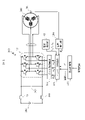
- FIG. 1 is a system configuration diagram including a motor control device;
- FIG. 3 is a detailed block configuration diagram of an inverter control unit;
- FIG. It is a current vector diagram.
- Fig. 10 is a graph showing a change map;
- (A), (B), and (C) are graphs showing application maps.
- 4A, 4B, and 4C are graphs showing current phase angles, combined current waveforms, and rotor phase angular velocities; 7 is a graph showing results of analysis of frequency components of torque of a motor;
- FIG. 1 is a system configuration diagram including a motor control device 100. As shown in FIG. A secondary battery 200 is connected to the motor control device 100 via a contactor 201 to supply DC power. A smoothing capacitor 202 is connected between the positive and negative sides of the supplied DC power. A three-phase alternating current output from the motor control device 100 is supplied to the motor 300 to drive the motor 300 . Motor 300 will be described as an example of a three-phase motor.
- a motor control device 100, a secondary battery 200, and a motor 300 are mounted on a vehicle such as a hybrid vehicle or an electric vehicle to drive the vehicle.
- the motor control device 100 includes an inverter 101 , a gate drive circuit 102 , a current detection section 103 , a position detection section 104 and an inverter control section 105 .
- the inverter 101 is composed of upper and lower arm circuits for three phases. Each arm circuit has a switching power semiconductor element and a diode. The power semiconductor element performs switching operation according to a driving signal output from the gate driving circuit 102 . Inverter 101 outputs a three-phase AC current based on the DC power supplied from secondary battery 200 by the switching operation of the power semiconductor element.
- Current detection unit 103 detects a three-phase alternating current output from inverter 101 to motor 300 and outputs current values iu, iv, and iw of each phase to inverter control unit 105 .
- Position detection unit 104 detects the rotational position of motor 300 using resolver 301 or the like, and outputs rotor phase angle ⁇ e to inverter control unit 105 .
- the inverter controller 105 Based on the current values iu, iv, and iw detected by the current detector 103 and the rotor phase angle ⁇ e detected by the position detector 104, the inverter controller 105 outputs voltage commands Vu, Vv, and Vw for each phase. is calculated to control the inverter 101 .
- inverter control unit 105 changes the current phase angle of motor 300 in the vicinity of the zero cross of the three-phase alternating current according to the time of occurrence of vibration of the vehicle, and changes the period of the combined current waveform of the three-phase alternating current. to reduce the impact on vehicle vibration.
- the vehicle control unit 400 determines the driving scene of the vehicle based on vehicle information such as the vehicle acceleration sensor value, vehicle speed, accelerator pedal opening, motor 300 rotation speed, and the like.
- the driving scene is a driving scene in which vibration or noise occurs, such as immediately after starting the vehicle, immediately before stopping the vehicle, or when traveling uphill.
- the determined driving scene is output to inverter control section 105 .
- Vehicle control unit 400 also outputs a torque command ⁇ * for driving motor 300 to inverter control unit 105 based on the vehicle information.
- the inverter control unit 105 and the vehicle control unit 400 may be configured by a computer having a CPU, memory, and the like.
- the computer performs processing by executing a program stored in a memory or the like.
- all or part of the processing may be implemented by a hard logic circuit.
- the program may be stored in a storage medium in advance and provided.
- the program may be provided through a network line. It may be provided as a computer readable computer program product in various forms such as a data signal (carrier wave).
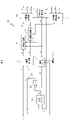
- FIG. 2 is a detailed block diagram of the inverter control unit 105.
- the inverter control unit 105 includes a current conversion unit 10, a d-axis conversion unit 11, a q-axis conversion unit 12, an angular velocity calculation unit 13, a dq coordinate conversion unit 14, a UVW coordinate conversion unit 15, a change map 16, an application map 17, and a multiplier. 18 and an adder 19 .
- the current conversion unit 10 converts the input torque command ⁇ * and current phase angle final value ⁇ * into a d-axis current command value i d *, q-axis current command value i q *.
- ⁇ a is the number of interlinkage magnetic fluxes
- Pn is the number of pole pairs
- Ld is the d-axis inductance
- Lq is the q-axis inductance.
- the current phase angle final value ⁇ * is the current phase angle ⁇ 1 * of the motor 300 calculated based on the information from the resolver 301 when the change map 16 described later is not applied.
- This current phase angle ⁇ 1 * is set to a current phase angle that provides an efficient d-axis current command value i d * and q-axis current command value i q * in consideration of field weakening.
- the d-axis converter 11 converts the d -axis current command value id* based on the rotor phase angular velocity ⁇ e obtained by the angular velocity calculator 13 and the d -axis current value id obtained by the UVW coordinate converter 15. It is converted into a d-axis voltage command value v d * and output to the dq coordinate conversion unit 14 .
- the q-axis conversion unit 12 converts the q -axis current command value iq * based on the rotor phase angular velocity ⁇ e obtained by the angular velocity calculation unit 13 and the q-axis current value iq obtained by the UVW coordinate conversion unit 15. It is converted into a q-axis voltage command value v q * and output to the dq coordinate conversion unit 14 .
- the dq coordinate conversion unit 14 converts the d -axis voltage command value vd* and the q -axis voltage command value vq* into UVW-phase three-phase voltage commands Vu, Vv, and Vw.
- the UVW coordinate conversion unit 15 converts the current values iu, iv, and iw of the three UVW phases into a d -axis current value id and a q -axis current value iq.
- the change map 16 is a map for changing the current phase angle of the motor in the vicinity of the zero cross of the three-phase alternating current.
- Current phase angle ⁇ 1 * and rotor phase angle ⁇ e are input, and current phase change value ⁇ 2 * is output.
- the application map 17 whose details will be described later, is input with the rotor phase angular velocity ⁇ e, the driving scene, and the torque command ⁇ *.
- a gain G representing the degree of application is output.
- a multiplier 18 multiplies the current phase change value ⁇ 2 * from the change map 16 based on the gain G from the application map 17 .
- the result of this multiplication is added to the current phase angle ⁇ 1 * in the adder 19 to obtain the current phase angle final value ⁇ *.
- the inverter control unit 105 controls the motor in the vicinity of the zero cross of the three-phase alternating current according to the time of occurrence of vehicle vibration without changing the torque command ⁇ *.
- the current phase angle ⁇ 1 * of 300 is changed to make the period of the composite current waveform of the three-phase alternating current irregular. This reduces the influence of the torque pulsation of the motor 300 on the vibration of the vehicle.
- FIG. 3 is a current vector diagram. As shown in FIG. 3, the horizontal direction is the ⁇ axis and the vertical direction is the ⁇ axis.
- the d-axis is the position shifted from the ⁇ -axis by the rotor phase angle ⁇ e, and the q-axis is the position 90 degrees from the d-axis.
- Torque ⁇ of motor 300 is represented by a combined vector of d-axis current command value i d * on the d-axis and q-axis current command value i q * on the q-axis.
- the current phase angle ⁇ 1 * is changed between the minimum value ⁇ ph1 * and the maximum value ⁇ ph2 *.
- the torque ⁇ of the motor 300 is kept on the isotorque curve T where the torque ⁇ is constant.
- inverter control unit 105 generates current command values id* and iq * that are equivalent to torque ⁇ of motor 300 before changing the current phase angle even if the current phase angle is changed.
- FIG. 3 shows the case where the rotor phase angle ⁇ e+current phase angle ⁇ 1 * is 5 ⁇ /6.
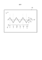
- FIG. 4 is a graph showing change map 16 .
- the horizontal axis indicates the input side (rotor phase angle ⁇ e+current phase angle ⁇ 1 *), and the vertical axis indicates the output side (current phase change value ⁇ 2 *).
- the rotor phase angle ⁇ e+current phase angle ⁇ 1 * is input to the input side, the corresponding current phase change value ⁇ 2 * shown in the graph is output.
- a current control cycle Ic corresponding to one cycle of the electrical angle of the three-phase alternating current is indicated by a dotted line on the horizontal axis of FIG.
- the current control cycle Ic has ⁇ /6, ⁇ /2, 5 ⁇ /6, 7 ⁇ /6, 3 ⁇ /2 and 11 ⁇ /6 as zero crossing points of the three-phase AC current.
- the current phase angle leads to the maximum value ⁇ ph2 *
- the current phase lags to the minimum value ⁇ ph1 . *become.
- obtaining a current phase change value ⁇ 2 * for changing the current phase angle in the range between the minimum value ⁇ ph1 * and the maximum value ⁇ ph2 * in the vicinity of the zero cross of the three-phase alternating current. can be done.
- the current (torque) pulsation of the 6th electrical angle is suppressed, component to reduce the impact on vehicle vibration.
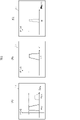
- FIG. 5A, 5B, and 5C are graphs showing the application map 17.
- FIG. Various information is input to the input side of the horizontal axis, and the gain G shown on the vertical axis is output according to the input information.
- the horizontal axis indicates the input side (rotor phase angular velocity ⁇ e)
- the vertical axis indicates the output side (gain G).
- FIG. 5A shows an example, but when the rotor phase angular velocity ⁇ e is ⁇ e1, the gain G is 1, and when the rotor phase angular velocity ⁇ e is ⁇ e2, the gain G is 0.5.
- the relationship between the rotor phase angular velocity ⁇ e of the motor 300 and the vibration of the vehicle is obtained in advance through experiments or the like in the vehicle and set as the application map 17 .
- the rotor phase angular velocity corresponding to the resonance point ⁇ e is set to ⁇ e1 as the resonant frequency range of the vehicle.
- ⁇ e2 is set, for example, when there is a resonance frequency of sound that is generated depending on the traveling speed of the vehicle.
- FIG. 5B shows an example of increasing the gain G when the torque command ⁇ * is ⁇ 1. This is set when the resonance point between vehicle vibration and torque pulsation is determined according to the torque command ⁇ *.
- a two-dimensional map using the torque command ⁇ * and the rotation speed of the motor 300 may be used instead of the torque command ⁇ *.
- the relationship between the rotation speed of the motor 300 and the gain G may be set in the application map 17 .
- FIG. 5C shows an example in which the driving scene increases the gain G at S1 immediately after the vehicle starts.
- the driving scene may be a scene in which vibration or noise occurs, such as when the vehicle is just before stopping or when the vehicle is traveling uphill.
- the gain G may be increased in the vicinity. Further, the application map 17 may be set by combining two or more of the rotor phase angular velocity ⁇ e, the torque command ⁇ *, the rotation speed of the motor 300, and the driving scene. The gain G may be increased when a combination satisfies a predetermined condition. When the motor 300 is operated under normal control, the application map 17 with zero gain G may be selected.
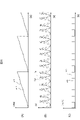
- FIG. 6A, 6B, and 6C are graphs showing current phase angles, combined current waveforms, and rotor phase angular velocities.
- FIG. 6A shows the current phase angle ⁇ 1 * and the current phase angle final value ⁇ * to which the change map 16 is applied by the application map 17 .
- the current phase angle final value ⁇ * indicated by the solid line the current phase angle advances and lags, deviating from the current phase angle ⁇ 1 * indicated by the broken line.
- FIG. 6B shows the composite current waveform I 1 m when the change map 16 is not applied and the composite current waveform Im when the change map 16 is applied by the application map 17 .
- the period of the composite current waveform I 1 m is regular, but the period of the composite current waveform Im is irregular.
- This combined current waveform Im is similar to the torque applied to the motor 300, and shifts the cycle of torque pulsation.
- FIG. 6C shows the rotor phase angular velocity ⁇ e 1 when the modification map 16 is not applied and the rotor phase angular velocity ⁇ e when the modification map 16 is applied by the application map 17 .
- the rotor phase angular velocity ⁇ e 1 is synchronous with the rotational speed of the motor 300 and is constant, the rotor phase angular velocity ⁇ e temporarily becomes asynchronous with the rotational speed of the motor 300 .
- FIG. 7 is a graph showing the analysis result of the frequency component of the torque of the motor 300. As shown in FIG. The horizontal axis is the frequency, and the vertical axis is the intensity of the frequency component.
- the frequency component F 1 m when the change map 16 is not applied and the frequency component Fm when the change map 16 is applied by the application map 17 are shown.
- the torque pulsation of the 6th electrical angle component increases at the frequency component F 1 m.
- this embodiment it is possible to suppress the torque pulsation of the sixth electrical angle component as indicated by the frequency component Fm without changing the torque command ⁇ *.
- the motor control device 100 includes an inverter 101 that supplies alternating current to a motor 300 mounted on a vehicle, a current detection unit 103 that detects the alternating current, and a position detection unit that detects the rotor phase angle of the motor 300. 104, and an inverter control unit 105 that controls the inverter 101 based on the current value detected by the current detection unit 103 and the rotor phase angle detected by the position detection unit 104.
- the inverter control unit 105 The current phase angle of the motor 300 is changed according to the time of occurrence of vibration of the vehicle to make the period of the synthesized current waveform of the alternating current irregular. As a result, the influence on vehicle vibration can be reduced by motor control according to the timing of occurrence of vehicle vibration.
- the motor control method includes an inverter 101 that supplies an AC current to a motor 300 mounted on a vehicle, a current detection unit 103 that detects the AC current, and a position detection unit 104 that detects the rotor phase angle of the motor 300. and an inverter control unit 105 that controls the inverter 101 based on the current value detected by the current detection unit 103 and the rotor phase angle detected by the position detection unit 104.
- the current phase angle of the motor 300 is changed according to the time of occurrence of vibration of the vehicle to make the cycle of the composite current waveform of alternating current irregular. As a result, the influence on vehicle vibration can be reduced by motor control according to the timing of occurrence of vehicle vibration.
- the present invention can be implemented by modifying the embodiments described above as follows.
- (1) the motor 300 is a three-phase motor and the alternating current is a three-phase alternating current, these are not limited to three-phase, and may be multi-phase.
- the present invention is not limited to the above-described embodiments, and other forms conceivable within the scope of the technical idea of the present invention are also included in the scope of the present invention as long as the features of the present invention are not impaired. . Moreover, it is good also as a structure which combined the above-mentioned embodiment and several modifications.
Landscapes
- Engineering & Computer Science (AREA)
- Power Engineering (AREA)
- Transportation (AREA)
- Mechanical Engineering (AREA)
- Control Of Ac Motors In General (AREA)
- Control Of Motors That Do Not Use Commutators (AREA)
Priority Applications (4)
| Application Number | Priority Date | Filing Date | Title |
|---|---|---|---|
| CN202280029224.8A CN117242694A (zh) | 2021-04-22 | 2022-02-15 | 电动机控制装置及电动机控制方法 |
| DE112022001154.8T DE112022001154T5 (de) | 2021-04-22 | 2022-02-15 | Motorsteuervorrichtung und motorsteuerverfahren |
| US18/555,569 US20240204705A1 (en) | 2021-04-22 | 2022-02-15 | Motor control device and motor control method |
| JP2023516300A JP7442736B2 (ja) | 2021-04-22 | 2022-02-15 | モータ制御装置およびモータ制御方法 |
Applications Claiming Priority (2)
| Application Number | Priority Date | Filing Date | Title |
|---|---|---|---|
| JP2021072462 | 2021-04-22 | ||
| JP2021-072462 | 2021-04-22 |
Publications (1)
| Publication Number | Publication Date |
|---|---|
| WO2022224559A1 true WO2022224559A1 (ja) | 2022-10-27 |
Family
ID=83722777
Family Applications (1)
| Application Number | Title | Priority Date | Filing Date |
|---|---|---|---|
| PCT/JP2022/005905 Ceased WO2022224559A1 (ja) | 2021-04-22 | 2022-02-15 | モータ制御装置およびモータ制御方法 |
Country Status (5)
| Country | Link |
|---|---|
| US (1) | US20240204705A1 (https=) |
| JP (1) | JP7442736B2 (https=) |
| CN (1) | CN117242694A (https=) |
| DE (1) | DE112022001154T5 (https=) |
| WO (1) | WO2022224559A1 (https=) |
Families Citing this family (2)
| Publication number | Priority date | Publication date | Assignee | Title |
|---|---|---|---|---|
| WO2023073870A1 (ja) * | 2021-10-28 | 2023-05-04 | 三菱電機株式会社 | 電力変換装置、モータ駆動装置および冷凍サイクル適用機器 |
| WO2023073880A1 (ja) * | 2021-10-28 | 2023-05-04 | 三菱電機株式会社 | 電力変換装置、モータ駆動装置および冷凍サイクル適用機器 |
Citations (2)
| Publication number | Priority date | Publication date | Assignee | Title |
|---|---|---|---|---|
| JP2013039033A (ja) * | 2012-09-28 | 2013-02-21 | Toshiba Mitsubishi-Electric Industrial System Corp | 多相電動機駆動装置 |
| JP2014057515A (ja) * | 2008-09-01 | 2014-03-27 | Mitsubishi Electric Corp | コンバータ回路、並びにそれを備えたモータ駆動制御装置、空気調和機、及び冷蔵庫 |
Family Cites Families (3)
| Publication number | Priority date | Publication date | Assignee | Title |
|---|---|---|---|---|
| JP5741966B2 (ja) * | 2012-12-03 | 2015-07-01 | 株式会社デンソー | 交流電動機の制御装置 |
| CN110235357B (zh) * | 2017-01-30 | 2022-12-13 | 日立安斯泰莫株式会社 | 逆变器控制装置 |
| US12199539B2 (en) * | 2020-04-06 | 2025-01-14 | Hitachi Astemo, Ltd. | Motor control device, electric vehicle, and motor control method |
-
2022
- 2022-02-15 DE DE112022001154.8T patent/DE112022001154T5/de active Pending
- 2022-02-15 JP JP2023516300A patent/JP7442736B2/ja active Active
- 2022-02-15 US US18/555,569 patent/US20240204705A1/en active Pending
- 2022-02-15 WO PCT/JP2022/005905 patent/WO2022224559A1/ja not_active Ceased
- 2022-02-15 CN CN202280029224.8A patent/CN117242694A/zh active Pending
Patent Citations (2)
| Publication number | Priority date | Publication date | Assignee | Title |
|---|---|---|---|---|
| JP2014057515A (ja) * | 2008-09-01 | 2014-03-27 | Mitsubishi Electric Corp | コンバータ回路、並びにそれを備えたモータ駆動制御装置、空気調和機、及び冷蔵庫 |
| JP2013039033A (ja) * | 2012-09-28 | 2013-02-21 | Toshiba Mitsubishi-Electric Industrial System Corp | 多相電動機駆動装置 |
Also Published As
| Publication number | Publication date |
|---|---|
| JPWO2022224559A1 (https=) | 2022-10-27 |
| DE112022001154T5 (de) | 2023-12-21 |
| JP7442736B2 (ja) | 2024-03-04 |
| CN117242694A (zh) | 2023-12-15 |
| US20240204705A1 (en) | 2024-06-20 |
Similar Documents
| Publication | Publication Date | Title |
|---|---|---|
| CN100514826C (zh) | 电动驱动控制装置及电动驱动控制方法 | |
| JP3755424B2 (ja) | 交流電動機の駆動制御装置 | |
| CN101647186B (zh) | 电力变换装置 | |
| JP5741966B2 (ja) | 交流電動機の制御装置 | |
| JPWO2018139295A1 (ja) | インバータ制御装置 | |
| JP2001245498A (ja) | 同期モータ制御装置及びそれを用いた車両 | |
| US8847527B2 (en) | Control system for a rotary machine | |
| JP2013162660A (ja) | 電動機駆動システム | |
| JP4715576B2 (ja) | 電動駆動制御装置及び電動駆動制御方法 | |
| JP7442736B2 (ja) | モータ制御装置およびモータ制御方法 | |
| US9716452B2 (en) | Rotation angle calculation device | |
| US10270380B2 (en) | Power converting apparatus and heat pump device | |
| US10193487B2 (en) | Control device for power conversion device, compressor drive system, flywheel power generating system, and control method of power conversion device | |
| JP2011211818A (ja) | 電力変換装置,電力変換方法及び電動機駆動システム | |
| WO2018139298A1 (ja) | 交流電動機の制御装置 | |
| JP2018182858A (ja) | 駆動装置 | |
| Kakodia et al. | A comparative study of DFOC and IFOC for IM drive | |
| Bak et al. | Torque predictive control for permanent magnet synchronous motor drives using indirect matrix converter | |
| JP5886117B2 (ja) | 交流電動機の制御装置 | |
| JP4007309B2 (ja) | モータ制御装置及びモータ制御方法 | |
| JP4581603B2 (ja) | 電動機駆動装置 | |
| JP2007274843A (ja) | 電動駆動制御装置及び電動駆動制御方法 | |
| CN106208862B (zh) | 电机的控制方法、控制装置和风机 | |
| JP2021108527A (ja) | 永久磁石同期機制御装置及びその方法 | |
| JP2005102385A (ja) | モーター制御装置 |
Legal Events
| Date | Code | Title | Description |
|---|---|---|---|
| 121 | Ep: the epo has been informed by wipo that ep was designated in this application |
Ref document number: 22791342 Country of ref document: EP Kind code of ref document: A1 |
|
| ENP | Entry into the national phase |
Ref document number: 2023516300 Country of ref document: JP Kind code of ref document: A |
|
| WWE | Wipo information: entry into national phase |
Ref document number: 18555569 Country of ref document: US |
|
| WWE | Wipo information: entry into national phase |
Ref document number: 112022001154 Country of ref document: DE |
|
| WWE | Wipo information: entry into national phase |
Ref document number: 202280029224.8 Country of ref document: CN |
|
| 122 | Ep: pct application non-entry in european phase |
Ref document number: 22791342 Country of ref document: EP Kind code of ref document: A1 |