WO2022220213A1 - 評価装置、評価方法及び評価装置用プログラム - Google Patents
評価装置、評価方法及び評価装置用プログラム Download PDFInfo
- Publication number
- WO2022220213A1 WO2022220213A1 PCT/JP2022/017471 JP2022017471W WO2022220213A1 WO 2022220213 A1 WO2022220213 A1 WO 2022220213A1 JP 2022017471 W JP2022017471 W JP 2022017471W WO 2022220213 A1 WO2022220213 A1 WO 2022220213A1
- Authority
- WO
- WIPO (PCT)
- Prior art keywords
- temperature
- evaluation
- temperature control
- control mechanism
- furnace
- Prior art date
- Legal status (The legal status is an assumption and is not a legal conclusion. Google has not performed a legal analysis and makes no representation as to the accuracy of the status listed.)
- Ceased
Links
Images


Classifications
-
- H—ELECTRICITY
- H01—ELECTRIC ELEMENTS
- H01M—PROCESSES OR MEANS, e.g. BATTERIES, FOR THE DIRECT CONVERSION OF CHEMICAL ENERGY INTO ELECTRICAL ENERGY
- H01M8/00—Fuel cells; Manufacture thereof
- H01M8/04—Auxiliary arrangements, e.g. for control of pressure or for circulation of fluids
- H01M8/04298—Processes for controlling fuel cells or fuel cell systems
- H01M8/04313—Processes for controlling fuel cells or fuel cell systems characterised by the detection or assessment of variables; characterised by the detection or assessment of failure or abnormal function
- H01M8/0432—Temperature; Ambient temperature
-
- H—ELECTRICITY
- H01—ELECTRIC ELEMENTS
- H01M—PROCESSES OR MEANS, e.g. BATTERIES, FOR THE DIRECT CONVERSION OF CHEMICAL ENERGY INTO ELECTRICAL ENERGY
- H01M8/00—Fuel cells; Manufacture thereof
- H01M8/04—Auxiliary arrangements, e.g. for control of pressure or for circulation of fluids
-
- F—MECHANICAL ENGINEERING; LIGHTING; HEATING; WEAPONS; BLASTING
- F27—FURNACES; KILNS; OVENS; RETORTS
- F27B—FURNACES, KILNS, OVENS OR RETORTS IN GENERAL; OPEN SINTERING OR LIKE APPARATUS
- F27B5/00—Muffle furnaces; Retort furnaces; Other furnaces in which the charge is held completely isolated
-
- F—MECHANICAL ENGINEERING; LIGHTING; HEATING; WEAPONS; BLASTING
- F27—FURNACES; KILNS; OVENS; RETORTS
- F27B—FURNACES, KILNS, OVENS OR RETORTS IN GENERAL; OPEN SINTERING OR LIKE APPARATUS
- F27B5/00—Muffle furnaces; Retort furnaces; Other furnaces in which the charge is held completely isolated
- F27B5/06—Details, accessories or equipment specially adapted for furnaces of these types
- F27B5/18—Arrangement of controlling, monitoring, alarm or like devices
-
- F—MECHANICAL ENGINEERING; LIGHTING; HEATING; WEAPONS; BLASTING
- F27—FURNACES; KILNS; OVENS; RETORTS
- F27D—DETAILS OR ACCESSORIES OF FURNACES, KILNS, OVENS OR RETORTS, IN SO FAR AS THEY ARE OF KINDS OCCURRING IN MORE THAN ONE KIND OF FURNACE
- F27D19/00—Arrangements of controlling devices
-
- H—ELECTRICITY
- H01—ELECTRIC ELEMENTS
- H01M—PROCESSES OR MEANS, e.g. BATTERIES, FOR THE DIRECT CONVERSION OF CHEMICAL ENERGY INTO ELECTRICAL ENERGY
- H01M8/00—Fuel cells; Manufacture thereof
- H01M8/04—Auxiliary arrangements, e.g. for control of pressure or for circulation of fluids
- H01M8/04298—Processes for controlling fuel cells or fuel cell systems
- H01M8/04694—Processes for controlling fuel cells or fuel cell systems characterised by variables to be controlled
- H01M8/04701—Temperature
-
- F—MECHANICAL ENGINEERING; LIGHTING; HEATING; WEAPONS; BLASTING
- F27—FURNACES; KILNS; OVENS; RETORTS
- F27B—FURNACES, KILNS, OVENS OR RETORTS IN GENERAL; OPEN SINTERING OR LIKE APPARATUS
- F27B5/00—Muffle furnaces; Retort furnaces; Other furnaces in which the charge is held completely isolated
- F27B5/06—Details, accessories or equipment specially adapted for furnaces of these types
- F27B2005/062—Cooling elements
-
- F—MECHANICAL ENGINEERING; LIGHTING; HEATING; WEAPONS; BLASTING
- F27—FURNACES; KILNS; OVENS; RETORTS
- F27D—DETAILS OR ACCESSORIES OF FURNACES, KILNS, OVENS OR RETORTS, IN SO FAR AS THEY ARE OF KINDS OCCURRING IN MORE THAN ONE KIND OF FURNACE
- F27D19/00—Arrangements of controlling devices
- F27D2019/0003—Monitoring the temperature or a characteristic of the charge and using it as a controlling value
-
- F—MECHANICAL ENGINEERING; LIGHTING; HEATING; WEAPONS; BLASTING
- F27—FURNACES; KILNS; OVENS; RETORTS
- F27D—DETAILS OR ACCESSORIES OF FURNACES, KILNS, OVENS OR RETORTS, IN SO FAR AS THEY ARE OF KINDS OCCURRING IN MORE THAN ONE KIND OF FURNACE
- F27D19/00—Arrangements of controlling devices
- F27D2019/0006—Monitoring the characteristics (composition, quantities, temperature, pressure) of at least one of the gases of the kiln atmosphere and using it as a controlling value
-
- F—MECHANICAL ENGINEERING; LIGHTING; HEATING; WEAPONS; BLASTING
- F27—FURNACES; KILNS; OVENS; RETORTS
- F27D—DETAILS OR ACCESSORIES OF FURNACES, KILNS, OVENS OR RETORTS, IN SO FAR AS THEY ARE OF KINDS OCCURRING IN MORE THAN ONE KIND OF FURNACE
- F27D19/00—Arrangements of controlling devices
- F27D2019/0028—Regulation
- F27D2019/0034—Regulation through control of a heating quantity such as fuel, oxidant or intensity of current
-
- F—MECHANICAL ENGINEERING; LIGHTING; HEATING; WEAPONS; BLASTING
- F27—FURNACES; KILNS; OVENS; RETORTS
- F27D—DETAILS OR ACCESSORIES OF FURNACES, KILNS, OVENS OR RETORTS, IN SO FAR AS THEY ARE OF KINDS OCCURRING IN MORE THAN ONE KIND OF FURNACE
- F27D19/00—Arrangements of controlling devices
- F27D2019/0028—Regulation
- F27D2019/0056—Regulation involving cooling
-
- H—ELECTRICITY
- H01—ELECTRIC ELEMENTS
- H01M—PROCESSES OR MEANS, e.g. BATTERIES, FOR THE DIRECT CONVERSION OF CHEMICAL ENERGY INTO ELECTRICAL ENERGY
- H01M8/00—Fuel cells; Manufacture thereof
- H01M8/10—Fuel cells with solid electrolytes
- H01M8/12—Fuel cells with solid electrolytes operating at high temperature, e.g. with stabilised ZrO2 electrolyte
- H01M2008/1293—Fuel cells with solid oxide electrolytes
-
- Y—GENERAL TAGGING OF NEW TECHNOLOGICAL DEVELOPMENTS; GENERAL TAGGING OF CROSS-SECTIONAL TECHNOLOGIES SPANNING OVER SEVERAL SECTIONS OF THE IPC; TECHNICAL SUBJECTS COVERED BY FORMER USPC CROSS-REFERENCE ART COLLECTIONS [XRACs] AND DIGESTS
- Y02—TECHNOLOGIES OR APPLICATIONS FOR MITIGATION OR ADAPTATION AGAINST CLIMATE CHANGE
- Y02E—REDUCTION OF GREENHOUSE GAS [GHG] EMISSIONS, RELATED TO ENERGY GENERATION, TRANSMISSION OR DISTRIBUTION
- Y02E60/00—Enabling technologies; Technologies with a potential or indirect contribution to GHG emissions mitigation
- Y02E60/30—Hydrogen technology
- Y02E60/50—Fuel cells
Definitions
- the present invention relates to an evaluation device, evaluation method, and evaluation device program for evaluating the performance of an evaluation target such as a fuel cell.
- An evaluation device that evaluates the electrical performance of an evaluation object such as a fuel cell by changing the temperature conditions (for example, Patent Document 1).
- the fuel cell is housed in a heating furnace, heated to a predetermined test temperature, and an evaluation test is performed at that test temperature.
- the heating furnace is stopped, and after the inside of the heating furnace is sufficiently cooled, the tester takes out the fuel cell and replaces it with the next fuel cell to be evaluated. are housed in
- the present invention has been made in view of such problems.
- the main task is to improve the operating rate of the evaluation test.
- an evaluation apparatus evaluates the performance of a predetermined evaluation object by changing temperature conditions, and includes a heating furnace having a furnace space for accommodating the evaluation object, and the evaluation object or its surroundings. a temperature control mechanism that heats or cools to control the temperature, a temperature acquisition unit that acquires the temperature of a plurality of locations on or around the evaluation object, and an absolute value of the temperature difference between the temperatures of the plurality of locations acquired by the temperature acquisition unit and a temperature control mechanism control section for controlling the temperature control mechanism so as to maintain the temperature at a predetermined value or less.
- the temperature control mechanism that heats or cools the evaluation target or its surroundings to control the temperature
- the evaluation target or its surroundings is controlled by the temperature control mechanism when the temperature inside the heating furnace is increased or decreased.
- the temperature control mechanism is controlled so that the temperature difference does not spread too much, so damage to the object to be evaluated due to the temperature difference in the heating furnace can be prevented. can also be suppressed.
- the temperature control mechanism control section controls the temperature control mechanism based on a temperature difference between the highest temperature and the lowest temperature among the temperatures at the plurality of locations acquired by the temperature acquisition section. In this way, it is possible to effectively suppress damage to the evaluation target due to the temperature difference in the heating furnace.
- the temperature control mechanism includes an outlet for supplying a temperature control fluid for promoting heating or cooling of the evaluation target to the furnace space.
- the heating furnace includes a heating element in the furnace space, and the outlet can be oriented so as to directly blow the temperature control fluid onto the heating element.
- the outlet can be oriented so as to directly blow the temperature control fluid onto the heating element. is preferably configured to In this way, by setting the direction of the outlet so that the temperature control fluid is directly sprayed onto the heating element of the heating furnace, it is possible to efficiently cool the space in the furnace when the temperature is lowered.
- the temperature control fluid whose temperature is higher than that of the heating element, the space inside the furnace can be heated efficiently.
- the direction of the air outlet can be set so as not to directly blow the temperature control fluid to the evaluation device housed in the furnace space. By doing so, damage to the evaluation target due to the temperature difference can be more effectively suppressed.
- the evaluation apparatus has a temperature raising operation mode in which the temperature inside the furnace is heated to raise the temperature.
- the temperature control mechanism is controlled so as to supply a temperature control fluid having a temperature higher than the temperature of the space.
- the temperature rise time can be shortened by accelerating the heating of the space inside the furnace while suppressing damage to the object to be evaluated due to the temperature difference in the heating furnace in the temperature rising operation mode.
- the evaluation apparatus has a temperature-lowering operation mode in which the temperature of the furnace space is lowered by cooling the furnace space. control the temperature control mechanism so as to supply a temperature control fluid having a temperature lower than the temperature. In this way, it is possible to reduce the temperature drop time by accelerating the heating of the space inside the furnace while suppressing damage to the evaluation target caused by the temperature difference in the heating furnace in the temperature drop operation mode.
- the heating furnace has an openable and closable outside air inlet for taking in outside air into the furnace space, and in the temperature lowering operation mode, the temperature of the object to be evaluated is set to a predetermined set temperature. It is preferable that the external air intake port is automatically opened to take in external air into the furnace space when the temperature falls below . In this way, the space inside the furnace can be cooled more effectively when the temperature is lowered. At this time, if the set temperature at which the outside air intake is opened is, for example, equal to or lower than the self-ignition temperature to be evaluated, the risk of ignition accompanying opening the outside air intake can be reduced.
- evaluation object in the evaluation device includes, for example, a fuel cell, a catalyst, or a sensor.
- the evaluation method of the present invention is an evaluation apparatus for evaluating the performance of a predetermined evaluation object by changing temperature conditions, comprising: a heating furnace having a furnace space for accommodating the evaluation object; and the evaluation object or its surroundings.
- a method of evaluating the evaluation object using an evaluation device equipped with a temperature control mechanism that heats or cools the The temperature control mechanism is controlled so as to maintain the absolute value of the temperature difference between the locations at a predetermined value or less.
- the evaluation device program of the present invention is an evaluation device that evaluates the performance of a predetermined evaluation object by changing temperature conditions, comprising: a heating furnace having a furnace space accommodating the evaluation object; A program for an evaluation device comprising a temperature control mechanism that heats or cools the surroundings thereof to control the temperature thereof, wherein the temperature acquisition unit acquires the temperatures of the evaluation object or its surroundings at a plurality of locations, and the acquired temperatures of the plurality of locations
- the computer is characterized by having a function as a temperature control mechanism control section that controls the temperature control mechanism so as to maintain the absolute value of the temperature difference below a predetermined value.
- an evaluation test can be performed while suppressing damage to the object to be evaluated due to temperature differences. rate can be improved.
- FIG. 10 is a diagram schematically showing the overall configuration of an evaluation device according to another embodiment of the present invention, showing a state in which the cover unit is in the closed position;
- FIG. 10 is a diagram schematically showing the overall configuration of an evaluation device according to another embodiment of the present invention, showing a state in which the cover unit is in the open position;
- the functional block diagram of the control apparatus of other one Embodiment of this invention The figure which shows typically the whole structure of the evaluation apparatus of other one Embodiment of this invention.
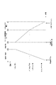
- 5 is a graph for explaining a cooling method in a cooling operation mode of the evaluation device of one embodiment of the present invention;
- the evaluation apparatus 100 of the present embodiment evaluates the performance of the fuel cell, which is the object W to be evaluated. It is for doing
- the cell performance of a fuel cell includes, for example, voltage and current that the fuel cell can generate, electrical performance such as the resistance value of the fuel cell, electrical performance when the ambient temperature changes, and the like.
- the evaluation test also includes a functionality test to test whether the fuel cell can be functionally maintained, such as by not damaging the fuel cell when the ambient temperature is changed.
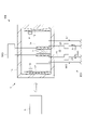
- the evaluation apparatus 100 includes a heating furnace 1 having a furnace space 1s for housing and heating a fuel cell W, and a power generation gas for supplying the fuel cell W with a gas for power generation.
- a supply system 2 and a control device 3 are provided.
- the evaluation device 100 has a temperature raising operation mode for raising the temperature of the furnace space 1 s and maintains the furnace space 1 s at a predetermined set temperature (also referred to as a test temperature). and a temperature-lowering operation mode for lowering the temperature of the furnace space 1s.
- the fuel cell W which is the evaluation target W, is a solid oxide fuel cell (SOFC) composed of a single cell including a solid electrolyte w1, an air electrode w2 (cathode), and a fuel electrode w3 (anode).
- SOFC solid oxide fuel cell
- the type of fuel cell is not limited to SOFC, for example polymer electrolyte fuel cell (PEFC), phosphoric acid fuel cell (PAFC), molten carbonate fuel cell (MCFC), alkaline electrolyte fuel cell (AFC). , direct fuel cell (DFC), or bio fuel cell (BFC).
- the heating furnace 1 includes a box-shaped furnace main body 11 that forms a furnace space 1s for housing the fuel cell W, and a heating element 12 that heats the furnace space 1s.
- the furnace body 11 has a bottom wall 11a on which the fuel cell W is mounted, a side wall 11b surrounding the side of the mounted fuel cell W, and a top wall 11c covering the top of the fuel cell W.
- a furnace space 1s is formed by the inner surfaces of the bottom wall 11a, the side walls 11b, and the upper wall 11c.
- the heating element 12 generates heat by being supplied with power from a power supply circuit (not shown), for example, and heats the inside of the furnace space 1s.
- the heating element 12 of this embodiment is installed in the vicinity of the side wall 11b in the furnace space 1s so as to surround the side peripheral surface of the mounted fuel cell W.
- the heating method of the heating furnace 1 is not limited to this, and may be one in which an electric current is passed through the furnace body 11 to cause resistance heating (Joule heating).
- the furnace body 11 is made of a conductive metal.
- the power generation gas supply system 2 is for supplying the inside of the fuel cell W with gas necessary for power generation.
- the power generation gas supply system 2 includes a fuel electrode pipe 21 that supplies a gas such as H2 gas to the fuel electrode w3 of the fuel cell W, and a gas such as air to the air electrode w2 of the fuel cell W. an air electrode pipe 22, a power generation temperature controller 23 for heating or cooling the gas flowing through each pipe, and a power generation flow control device (not shown) for controlling the flow rate of the gas flowing through each pipe. .
- the power generation temperature control device 23 includes one or both of a heater and a cooler, and controls the heater and / or cooler according to a control signal output from the control device 3, It is configured to adjust the gas flowing through each pipe to a predetermined temperature.
- the flow control device includes, for example, a mass flow controller, a flow control valve, etc., and adjusts the gas flowing through each pipe to a predetermined flow rate according to the control signal output from the control device 3. is configured to
- the control device 3 controls the environmental conditions of the fuel cell W and evaluates the characteristics of the fuel cell W.
- the control device 3 is a general-purpose or special-purpose computer equipped with a CPU, a memory, an input/output interface, and the like.
- the control device 3 cooperates with the CPU and peripheral devices according to a predetermined program stored in a predetermined area of the memory, so that, as shown in FIG. and a power generation control unit 32 for controlling the power generation operation of the fuel cell W, and an electricity measuring unit 33 for evaluating the electrical characteristics of the fuel cell W.
- the furnace control unit 31 controls the power supply circuit of the heating furnace 1 so that the temperature of the furnace space 1s reaches a predetermined test temperature.
- the evaluation device 100 can switch between three operation modes: a temperature increasing operation mode, a temperature maintaining mode, and a temperature decreasing operation mode.
- the power generation control unit 32 controls the power generation operation of the fuel cell W by controlling the power generation gas supply system 2 . Specifically, the power generation control unit 32 transmits a control signal to the power generation temperature control device 23 and the power generation flow rate control device provided in the power generation gas supply system 2, and supplies the control signal to the air electrode w2 and the fuel electrode w3 of the fuel cell W. It is configured to control the temperature, flow rate and pressure of the gas for power generation.
- the electrical measuring unit 33 acquires a measurement signal from an electrical measuring device such as an impedance analyzer or a cell voltage monitor (not shown) connected to the fuel cell W, and measures the fuel cell in the temperature increasing operation mode, the temperature maintaining mode and/or the temperature decreasing operation mode. It measures electrical properties of W such as resistance, current or voltage.
- an electrical measuring device such as an impedance analyzer or a cell voltage monitor (not shown) connected to the fuel cell W, and measures the fuel cell in the temperature increasing operation mode, the temperature maintaining mode and/or the temperature decreasing operation mode. It measures electrical properties of W such as resistance, current or voltage.
- the evaluation apparatus 100 of the present embodiment heats and cools the fuel cell W and its surroundings in the temperature increasing operation mode and the temperature decreasing operation mode, thereby accelerating the temperature increase and temperature decrease of the fuel cell W and its surroundings.
- a temperature control mechanism C is provided for this purpose.
- the control device 3 is further configured to function as a temperature acquisition unit 34 that acquires temperatures at a plurality of locations in the heating furnace 1 and a temperature control mechanism control unit 35 that controls the temperature control mechanism C. .
- the temperature control mechanism C of the present embodiment is configured using a temperature control fluid supply system 4 that supplies air, which is a temperature control fluid whose temperature is adjusted by heating or cooling, to the furnace space 1 s of the heating furnace 1. .
- the temperature control fluid supply system 4 supplies the temperature control fluid from the bottom to the top in the furnace space 1s. 41, a temperature control device 42 for heating or cooling the temperature control fluid flowing through the temperature control fluid pipe 41, and a flow control device (not shown) for controlling the flow rate of the temperature control fluid flowing through the temperature control fluid pipe 41. I have.
- the temperature control fluid pipe 41 is provided so as to penetrate the furnace body 11, for example, the bottom wall 11a or the side wall 11b.
- the temperature control fluid pipe 41 has an upstream end connected to a gas source such as a gas cylinder, and a downstream end formed with a gas outlet 4g for blowing out air, which is a temperature control fluid.
- the gas outlet 4g is near the inner surface (bottom surface) of the bottom wall 11a of the furnace main body 11 and between the side surface of the fuel cell W placed and the heating element 12 disposed near the side wall 11b of the furnace main body 11. formed.
- the direction of the gas outlet 4g is adjustable (changeable).
- the gas outlet 4g is open to face the heating element 12 of the heating furnace 1, so that the temperature-controlled fluid flowing through the temperature-controlled fluid pipe 41 is directly blown toward the heating element 12. Its orientation is set.
- the direction of the gas outlet 4g is set so as not to directly blow the temperature-controlled fluid flowing through the temperature-controlled fluid pipe 41 to the side surface of the fuel cell W.
- the gas outlet 4g may be configured such that its direction can be automatically changed according to the temperature acquired by one or more of the plurality of temperature sensors 5, which will be described later.
- the temperature control device 42 includes one or both of a heater and a cooler, and controls the heater and/or the cooler according to a control signal output from the temperature control mechanism control unit 35, It is configured to adjust the temperature control fluid flowing through the temperature control fluid pipe 41 to a predetermined temperature.
- the flow rate control device includes, for example, a mass flow controller or a flow rate control valve. to a predetermined flow rate.
- the temperature acquisition unit 34 acquires a plurality of temperatures detected by a plurality of temperature sensors 5 provided inside the heating furnace 1 .
- the plurality of temperature sensors 5 are configured including, for example, thermocouples, etc., and are provided in the fuel cell W and its surroundings.
- a plurality of temperature sensors 5 of this embodiment are provided, for example, near the surface of the fuel cell W and near the surface of the heating element 12 of the heating furnace 1. It is configured to acquire the temperature and the temperature near the surface of the heating element 12 .
- the temperature sensor 5 may be provided inside the fuel cell W.
- the temperature acquisition unit 34 stores temperature data in which one or more temperatures acquired from each temperature sensor 5 and the elapsed time or time are linked in a predetermined storage unit set in the memory of the control device 3. may be configured to
- the temperature control mechanism control unit 35 of the present embodiment outputs a control signal to one or both of the temperature control device 42 and the fluid control device included in the temperature control fluid supply system 4 to control the temperature control fluid supply system 4. to control one or both of the temperature and flow rate of the temperature control fluid supplied from to the furnace space 1s.
- the temperature control mechanism control unit 35 supplies a temperature control fluid having a temperature higher than the temperature of the furnace space 1s (for example, the lowest temperature among the plurality of temperatures acquired by the temperature acquisition unit 34).
- the temperature control fluid supply system 4 is controlled so as to Further, in the temperature lowering operation mode, the temperature control mechanism control unit 35 supplies a temperature control fluid having a temperature lower than the temperature of the furnace space 1s (for example, the highest temperature among the plurality of temperatures acquired by the temperature acquisition unit 34). to control the temperature control fluid supply system 4. On the other hand, in the temperature maintenance mode, the temperature control mechanism control unit 35 closes the on-off valve provided in the temperature control fluid supply system 4 to supply the temperature control fluid so as not to supply the temperature control fluid to the furnace space 1s. Control system 4.
- the temperature control mechanism control unit 35 controls the temperature control fluid supplied from the temperature control fluid supply system 4 based on the temperature difference of the plurality of locations acquired by the temperature acquisition unit 34 . is configured to control one or both of the temperature and flow rate of the More specifically, the temperature control mechanism control unit 35 detects two temperatures (for example, different A difference ⁇ T between the temperatures Ta and Tb at two points, or the temperature Ta near the surface of the fuel cell W and the temperature Tb near the surface of the heating element 12, etc.) is calculated.
- two temperatures for example, different A difference ⁇ T between the temperatures Ta and Tb at two points, or the temperature Ta near the surface of the fuel cell W and the temperature Tb near the surface of the heating element 12, etc.
- the temperature control mechanism control unit 35 compares the absolute value of the temperature difference ⁇ T with a predetermined value Tx, and supplies the temperature control fluid so that the absolute value of the temperature difference ⁇ T is maintained at the predetermined value Tx or less. It controls the temperature or flow rate of the temperature control fluid supplied from system 4 .
- the predetermined value Tx is set to be sufficiently smaller than the temperature difference that causes damage such as cracks in the fuel cell W to be evaluated.
- the temperature control mechanism control unit 35 supplies a temperature control fluid having a temperature higher than the temperature of the furnace space 1 s while the furnace space 1 s is being heated by the heating furnace 1 in the temperature raising operation mode.
- the temperature control fluid supply system 4 is controlled so as to
- the temperature control mechanism control unit 35 constantly calculates the temperature difference ⁇ T between the two temperatures Ta and Tb acquired by the temperature acquisition unit 34, and when the absolute value of the temperature difference ⁇ T exceeds a predetermined value Tx, the temperature One or both of the temperature and flow rate of the temperature control fluid supplied from the temperature control fluid supply system 4 is controlled so that the absolute value of the difference ⁇ T is equal to or less than the predetermined value Tx.
- the temperature control mechanism control unit 35 supplies a temperature control fluid having a temperature lower than the temperature of the furnace space 1 s while the heating of the furnace space 1 s by the heating furnace 1 is stopped. It controls the temperature control fluid supply system 4 . Then, the temperature control mechanism control unit 35 calculates the temperature difference ⁇ T between the two temperatures Ta and Tb acquired by the temperature acquisition unit 34, and when the absolute value of the temperature difference ⁇ T exceeds a predetermined value Tx, the temperature difference One or both of the temperature and flow rate of the temperature control fluid supplied from the temperature control fluid supply system 4 is controlled so that the absolute value of ⁇ T is equal to or less than a predetermined value Tx. In the temperature-lowering operation mode, since the vicinity of the junction of dissimilar materials is likely to be damaged due to the temperature difference, one or more temperature sensors 5 are installed in the vicinity of the junction of dissimilar materials on the surface or inside of the evaluation target X. preferable.
- the evaluation apparatus 100 of the present embodiment configured as described above, since it is provided with the temperature control mechanism C for controlling the temperature by heating or cooling the evaluation target W or its surroundings, By heating or cooling the evaluation object W or its surroundings with the temperature control mechanism C, the temperature rising time or the temperature falling time can be shortened, and the test operation rate can be improved. Moreover, since the temperature of the evaluation object W or a plurality of locations around it is acquired and the temperature control mechanism C is controlled so that the temperature difference does not spread too much, the evaluation object caused by the temperature difference in the heating furnace 1 Damage to W can also be suppressed.
- the direction of the gas outlet 4g is set so that the temperature-controlled fluid supplied from the temperature-controlled fluid supply system 4 is directly blown onto the heating element 12 of the heating furnace 1, the space 1s in the furnace is reduced when the temperature is lowered. Cooling can proceed efficiently.
- the direction of the gas outlet 4g is set so that the temperature control fluid does not directly blow to the evaluation device 100 accommodated in the furnace space 1s, the evaluation object W damage can be more effectively suppressed.
- the present invention is not limited to the above embodiments.
- the temperature control mechanism C is configured using the temperature control fluid supply system 4, but it is not limited to this.
- the temperature control mechanism C of another embodiment may be configured using the power generation gas supply system 2 .
- the temperature control mechanism C uses the gas supply system 2 for power generation to supply a temperature control fluid whose temperature is adjusted by heating or cooling to the inside of the fuel cell W, so that the fuel cell W and its surroundings It may be configured to promote temperature rise and temperature drop of the temperature.
- the power generation gas supply system 2 supplies the temperature control fluid to the fuel electrode w3 through the fuel electrode pipe 21, and supplies the temperature control fluid to the air electrode w2 through the air electrode pipe 22.
- the temperature control mechanism control unit 35 controls the power generation temperature control device 23 and the power generation flow rate control device, and controls the temperature and flow rate of the temperature control fluid supplied to the fuel electrode w3 and the air electrode w2. Heating and cooling of the fuel cell W may be facilitated by controlling one or both.
- the temperature control fluid supplied into the fuel cell W using the power generation gas supply system 2 may be an inert gas such as nitrogen gas, a gas such as air or water vapor, a liquid such as water, or a gas-liquid mixture of these. It may be a mixture.
- the plurality of temperature sensors 5 are provided at least inside the fuel cell W and near the surface of the heating element 12 of the heating furnace 1. It may be configured to acquire at least the temperature and the temperature near the surface of the heating element 12 . Then, the temperature control mechanism control unit 35 compares the absolute value of the temperature difference ⁇ T between the internal temperature of the fuel cell W and the temperature near the surface of the heating element 12 with a predetermined value Tx, and determines the absolute value of the temperature difference ⁇ T. may be configured to control the temperature or flow rate of the temperature control fluid supplied into the fuel cell W so as to maintain the temperature below a predetermined value Tx.
- the temperature control mechanism C of another embodiment may be configured to accelerate the temperature rise and fall of the temperature of the fuel cell W and its surroundings by utilizing the exothermic reaction and the endothermic reaction of the fuel cell W.
- the temperature control mechanism C of this embodiment as shown in FIG.
- the power generation control section 32 functions as the temperature control mechanism control section 35 .
- the power generation gas supply system 2 of this embodiment is configured to supply water to the air electrode w2 and the fuel electrode w3 of the fuel cell W. As shown in FIG.
- the power generation control unit 32 which is the temperature control mechanism control unit 35, controls the power generation gas supply system 2 to operate the fuel cell W to generate power, and the exothermic reaction caused by this causes the fuel cell to generate power. Heat W.
- the temperature control mechanism control unit 35 compares the absolute value of the temperature difference ⁇ T between the internal temperature of the fuel cell W acquired by the temperature acquisition unit 34 and the temperature near the surface of the heating element 12 with a predetermined value Tx, and The flow rate of the power generation gas supplied into the fuel cell W may be controlled so as to maintain the absolute value of the temperature difference ⁇ T at a predetermined value Tx or less.
- the power generation control unit 32 which is the temperature control mechanism control unit 35, controls the power generation gas supply system 2 to supply water to the air electrode w2 and the fuel electrode w3 of the fuel cell W, and the power supply circuit.
- the power generation control unit 32 controls the power generation gas supply system 2 to supply water to the air electrode w2 and the fuel electrode w3 of the fuel cell W, and the power supply circuit.
- the temperature control mechanism control unit 35 compares the absolute value of the temperature difference ⁇ T between the internal temperature of the fuel cell W acquired by the temperature acquisition unit 34 and the temperature near the surface of the heating element 12 with a predetermined value Tx, and It may be configured to control the voltage value applied to the fuel cell W so as to maintain the absolute value of the temperature difference ⁇ T at a predetermined value Tx or less.
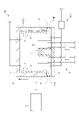
- the evaluation apparatus 100 of another embodiment includes a water cooling mechanism 7 that cools the furnace body 11 by water cooling, and the temperature control mechanism C may be configured using the water cooling mechanism 7. .
- the temperature control mechanism C functions to promote cooling around the fuel cell W in the temperature decreasing operation mode.
- the water cooling mechanism 7 includes a water cooling pipe 71 through which a cooling medium such as cooling water flows, and a chiller or the like (not shown) that supplies cooling water to the water cooling pipe 71 .
- This water cooling pipe 71 may be provided so as to pass through the side wall 11b of the furnace body 11, for example.
- the control device 3 may further function as an outside air intake control section 36 that controls the open/closed state of the outside air intake 1x.
- the furnace body 11 of the heating furnace 1 includes a base unit 1b including a bottom wall 11a, an upper wall 11c and side walls 11b, and a cover unit 1a for covering the fuel cell W mounted on the base unit 1b.
- the heating furnace 1 has an elevating mechanism (not shown) for vertically moving the cover unit 1a with respect to the base unit 1b.
- the elevating mechanism moves the cover unit 1a up and down in response to a control signal output from the control device 3, thereby bringing the cover unit 1a into contact with the base unit 1b and closing the furnace space 1s to the closing position P. , and an open position Q where the furnace space 1s is opened by separating from the base unit 1b.
- the outside air intake port 1x is formed by a gap formed between the cover unit 1a and the base unit 1b which are separated from each other.
- the open air intake 1x is automatically switched from the closed state to the open state.
- the outside air intake control unit 36 sets the temperature Te of the evaluation object W acquired by the temperature acquisition unit 34 and the predetermined set temperature Ti (hereinafter referred to as outside air intake temperature Ti) is configured to compare with Then, when the temperature Te of the evaluation object W falls below the outside air intake temperature Ti, the outside air intake control unit 36 outputs a control signal to the lifting mechanism to move the cover unit 1a up and down from the closed position P to the open position Q.
- the outside air intake temperature Ti is a temperature set based on the spontaneous ignition temperature of the evaluation device 100. More specifically, it is lower than the spontaneous ignition temperature of the evaluation device 100, and the fuel cell W can be taken out. higher than the normal temperature.
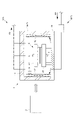
- the evaluation device 100 of another embodiment may include a plurality of temperature control mechanisms C of different methods.
- the evaluation apparatus 100 of another embodiment uses, as the plurality of temperature control mechanisms C, a first temperature control mechanism C1 using a temperature control fluid supply system 4 and a power generation gas supply system 2, as shown in FIG. a second temperature control mechanism C2, a third temperature control mechanism C3 that utilizes the exothermic and endothermic reactions of the fuel cell W, and a fourth temperature control mechanism C4 that utilizes the water cooling mechanism 7.
- a combination of mechanisms may be provided.
- the temperature control mechanism control unit 35 is configured to promote heating or cooling of the fuel cell W using a part or all of the temperature control mechanisms C1 to C4 selected from the plurality of temperature control mechanisms C1 to C4 in the temperature increasing operation mode and the temperature decreasing operation mode.
- the temperature control mechanisms C1 to C4 selected from the plurality of temperature control mechanisms C1 to C4 in the temperature increasing operation mode and the temperature decreasing operation mode.
- Tt predetermined test temperature
- the temperature of the fuel cell W is lowered by switching to the temperature lowering operation mode. While the temperature Te is equal to or lower than the test temperature Tt and equal to or higher than the outside air intake temperature Ti, cooling of the fuel cell W is accelerated using one or more selected from the first temperature control mechanism C1 to the fourth temperature control mechanism C4.
- the fuel cell W may be cooled by taking outside air into the in-furnace space 1s by opening the inlet 1x.
- the outside air intake 1x may be configured as an outlet for taking out the evaluation target W.
- the gas outlet 4g provided in the temperature control fluid supply mechanism opens so as to face the side wall 11b of the furnace main body 11, but it is not limited to this.
- the direction of the gas outlet 4g provided in the temperature control fluid supply mechanism is set so as to directly blow the temperature control gas to the side surface of the fuel cell W.
- the direction of the gas outlet 4g may be set so as to blow out the temperature control gas upward.
- the temperature control fluid supply system 4 is configured to supply the temperature control fluid from the bottom to the top in the furnace space 1s from the viewpoint of preventing hydrogen leakage, but the present invention is not limited to this. .
- the temperature-adjusting fluid supply system 4 may be configured to supply the temperature-adjusting fluid downward in the furnace space 1s.
- the fuel cell W which is the evaluation target W, is composed of a single cell including the solid electrolyte w1, the air electrode w2 (cathode), and the fuel electrode w3 (anode). Not exclusively.
- the fuel cell W may be configured by stacking a plurality of unit cells.
- the evaluation apparatus 100 of another embodiment may have a holder 8 that sandwiches and holds the fuel cell W in the in-furnace space 1s.
- the holding table 8 may have a base plate 81 on which the fuel cell W is mounted, and an upper plate 82 for holding down the upper surface of the mounted fuel cell W.
- the temperature acquisition unit 34 acquires the temperature detected by the plurality of temperature sensors 5 provided on the holding table 8 (for example, the temperature of the upper portion and the temperature of the lower portion of the fuel cell W), and the temperature control mechanism control unit 35
- the temperature control mechanism C may be controlled based on the temperature difference between the upper temperature and the lower temperature of the fuel cell W.
- the plurality of temperature sensors 5 provided in the heating furnace 1 may be installed at arbitrary locations, not limited to near the surface of the fuel cell W, inside the fuel cell W, and near the surface of the heating element 12 .
- the object W to be evaluated was the fuel cell W, but it is not limited to this.
- An object W to be evaluated in another embodiment may be, for example, a catalyst provided in an automobile exhaust pipe or the like, or various sensors such as an A/F sensor and an O2 sensor for detecting components in exhaust gas. That is, the present invention can be applied not only to the evaluation device 100 of the fuel cell W, but also to the evaluation device 100 that evaluates the performance of the evaluation object W that is a combination of various sensors, catalysts, or these.
- the operation rate of the evaluation test is improved while suppressing damage to the object to be evaluated due to the temperature difference.
Landscapes
- Engineering & Computer Science (AREA)
- Life Sciences & Earth Sciences (AREA)
- Manufacturing & Machinery (AREA)
- Sustainable Development (AREA)
- Sustainable Energy (AREA)
- Chemical & Material Sciences (AREA)
- Chemical Kinetics & Catalysis (AREA)
- Electrochemistry (AREA)
- General Chemical & Material Sciences (AREA)
- Mechanical Engineering (AREA)
- General Engineering & Computer Science (AREA)
- Fuel Cell (AREA)
Priority Applications (4)
| Application Number | Priority Date | Filing Date | Title |
|---|---|---|---|
| US18/286,606 US20240204223A1 (en) | 2021-04-12 | 2022-04-11 | Evaluation device, evaluation method, and program for evaluation device |
| JP2023514639A JP7774042B2 (ja) | 2021-04-12 | 2022-04-11 | 評価装置、評価方法及び評価装置用プログラム |
| CN202280027418.4A CN117178398A (zh) | 2021-04-12 | 2022-04-11 | 评价装置、评价方法以及评价装置用程序 |
| EP22788138.0A EP4325607A4 (en) | 2021-04-12 | 2022-04-11 | EVALUATION DEVICE, EVALUATION METHOD, AND PROGRAM FOR AN EVALUATION DEVICE |
Applications Claiming Priority (2)
| Application Number | Priority Date | Filing Date | Title |
|---|---|---|---|
| JP2021067325 | 2021-04-12 | ||
| JP2021-067325 | 2021-04-12 |
Publications (1)
| Publication Number | Publication Date |
|---|---|
| WO2022220213A1 true WO2022220213A1 (ja) | 2022-10-20 |
Family
ID=83640086
Family Applications (1)
| Application Number | Title | Priority Date | Filing Date |
|---|---|---|---|
| PCT/JP2022/017471 Ceased WO2022220213A1 (ja) | 2021-04-12 | 2022-04-11 | 評価装置、評価方法及び評価装置用プログラム |
Country Status (5)
| Country | Link |
|---|---|
| US (1) | US20240204223A1 (https=) |
| EP (1) | EP4325607A4 (https=) |
| JP (1) | JP7774042B2 (https=) |
| CN (1) | CN117178398A (https=) |
| WO (1) | WO2022220213A1 (https=) |
Cited By (1)
| Publication number | Priority date | Publication date | Assignee | Title |
|---|---|---|---|---|
| DE102023210744A1 (de) | 2023-10-30 | 2025-04-30 | Robert Bosch Gesellschaft mit beschränkter Haftung | Testvorrichtung für eine schnelle elektrochemische Charakterisierung einer elekt-rochemische Zelle, Verfahren zum Betrieb der Testvorrichtung und Verwendung der Testvorrichtung |
Families Citing this family (1)
| Publication number | Priority date | Publication date | Assignee | Title |
|---|---|---|---|---|
| CN115000470B (zh) * | 2022-08-02 | 2022-11-11 | 中汽研新能源汽车检验中心(天津)有限公司 | 燃料电池温控系统及其温控方法 |
Citations (5)
| Publication number | Priority date | Publication date | Assignee | Title |
|---|---|---|---|---|
| JP2001156010A (ja) * | 1999-11-25 | 2001-06-08 | Nec Corp | ランプアニール装置とその処理温度制御システム |
| JP2009129913A (ja) * | 2007-11-22 | 2009-06-11 | Nara Cell-Tech Corp | 燃料電池の電気化学的特性評価装置 |
| JP2010071935A (ja) * | 2008-09-22 | 2010-04-02 | Seiko Epson Corp | ワーク温度調整装置およびこれを備えた耐食試験装置 |
| JP2019200887A (ja) | 2018-05-15 | 2019-11-21 | 株式会社チノー | セル評価システム及び方法 |
| JP2020077640A (ja) * | 2018-11-07 | 2020-05-21 | バイス ウンベルトテヒニク ゲゼルシャフト ミット ベシュレンクテル ハフツング | 試験室及び制御方法 |
Family Cites Families (5)
| Publication number | Priority date | Publication date | Assignee | Title |
|---|---|---|---|---|
| JPS5572847A (en) * | 1978-11-28 | 1980-06-02 | Daido Steel Co Ltd | Temperature control method for electric furnace for high-temperature tension tester |
| JPH07270303A (ja) * | 1994-04-01 | 1995-10-20 | Katoo:Kk | 環境試験装置 |
| KR100992170B1 (ko) * | 2008-02-29 | 2010-11-05 | 부산대학교 산학협력단 | 연료전지 운전장치 평가시스템 |
| US8333125B2 (en) * | 2010-01-19 | 2012-12-18 | Atomic Energy Council—Institute of Nuclear Energy Research | Environmentally friendly, energy-economic system for testing fuel cell stacks |
| JP2018138502A (ja) * | 2017-02-24 | 2018-09-06 | 第一熱研株式会社 | セラミックスの製造方法及び制御装置 |
-
2022
- 2022-04-11 US US18/286,606 patent/US20240204223A1/en active Pending
- 2022-04-11 WO PCT/JP2022/017471 patent/WO2022220213A1/ja not_active Ceased
- 2022-04-11 EP EP22788138.0A patent/EP4325607A4/en active Pending
- 2022-04-11 CN CN202280027418.4A patent/CN117178398A/zh active Pending
- 2022-04-11 JP JP2023514639A patent/JP7774042B2/ja active Active
Patent Citations (5)
| Publication number | Priority date | Publication date | Assignee | Title |
|---|---|---|---|---|
| JP2001156010A (ja) * | 1999-11-25 | 2001-06-08 | Nec Corp | ランプアニール装置とその処理温度制御システム |
| JP2009129913A (ja) * | 2007-11-22 | 2009-06-11 | Nara Cell-Tech Corp | 燃料電池の電気化学的特性評価装置 |
| JP2010071935A (ja) * | 2008-09-22 | 2010-04-02 | Seiko Epson Corp | ワーク温度調整装置およびこれを備えた耐食試験装置 |
| JP2019200887A (ja) | 2018-05-15 | 2019-11-21 | 株式会社チノー | セル評価システム及び方法 |
| JP2020077640A (ja) * | 2018-11-07 | 2020-05-21 | バイス ウンベルトテヒニク ゲゼルシャフト ミット ベシュレンクテル ハフツング | 試験室及び制御方法 |
Non-Patent Citations (1)
| Title |
|---|
| See also references of EP4325607A4 |
Cited By (1)
| Publication number | Priority date | Publication date | Assignee | Title |
|---|---|---|---|---|
| DE102023210744A1 (de) | 2023-10-30 | 2025-04-30 | Robert Bosch Gesellschaft mit beschränkter Haftung | Testvorrichtung für eine schnelle elektrochemische Charakterisierung einer elekt-rochemische Zelle, Verfahren zum Betrieb der Testvorrichtung und Verwendung der Testvorrichtung |
Also Published As
| Publication number | Publication date |
|---|---|
| CN117178398A (zh) | 2023-12-05 |
| JP7774042B2 (ja) | 2025-11-20 |
| EP4325607A4 (en) | 2025-08-27 |
| JPWO2022220213A1 (https=) | 2022-10-20 |
| US20240204223A1 (en) | 2024-06-20 |
| EP4325607A1 (en) | 2024-02-21 |
Similar Documents
| Publication | Publication Date | Title |
|---|---|---|
| KR100530690B1 (ko) | 상이한 열 캐패시티들을 갖는 수소화물들을 이용하는 연료셀들의 냉온 동작을 위한 방법 및 장치 | |
| JP5100912B1 (ja) | 水素生成装置およびこれを備える燃料電池システム | |
| WO2022220213A1 (ja) | 評価装置、評価方法及び評価装置用プログラム | |
| CA3008768C (en) | Fuel cell system and controlling method of same | |
| JP5106867B2 (ja) | 燃料電池システム | |
| Schießwohl et al. | Experimental investigation of parameters influencing the freeze start ability of a fuel cell system | |
| JPS58112262A (ja) | 燃料電池の温度制御装置 | |
| US8349505B2 (en) | Power generation system of fuel cell and control method thereof | |
| KR20110006055A (ko) | 저온형 연료전지 스택의 냉각 장치 및 그 제어방법 | |
| CA3008596C (en) | Fuel cell system and controlling method of them | |
| JP2005322527A (ja) | 燃料電池システム | |
| Cano et al. | Free air breathing proton exchange membrane fuel cell: Thermal behavior characterization near freezing temperature | |
| KR101983815B1 (ko) | 연료전지 냉각시스템 | |
| US10483570B2 (en) | Fuel cell and method for operating the same | |
| JP5269107B2 (ja) | 冷却装置を含んだウエハー検査システム | |
| JP3815303B2 (ja) | 燃料電池システム | |
| US7597975B2 (en) | Fuel cell operation to minimize RH cycles to improve durability | |
| JP2007317553A (ja) | 燃料電池システム | |
| JP6390253B2 (ja) | 燃料電池発電システム | |
| KR20170007056A (ko) | 연료전지 차량 냉각계 유량 조절기구 및 그 제어방법 | |
| US20250316725A1 (en) | Fuel Cell Air Recirculation System and Control Method | |
| KR20240138295A (ko) | 공기 가열을 이용한 오픈 캐소드 연료전지 스택 열관리 시스템 | |
| KR101611064B1 (ko) | 연료전지 스택의 온도제어장치 | |
| KR20240138296A (ko) | 단락회로를 이용한 오픈 캐소드 연료전지 스택 열관리 시스템 | |
| Chen et al. | Experimental study on cold start strategy of high-power fuel cell system |
Legal Events
| Date | Code | Title | Description |
|---|---|---|---|
| 121 | Ep: the epo has been informed by wipo that ep was designated in this application |
Ref document number: 22788138 Country of ref document: EP Kind code of ref document: A1 |
|
| WWE | Wipo information: entry into national phase |
Ref document number: 2023514639 Country of ref document: JP |
|
| WWE | Wipo information: entry into national phase |
Ref document number: 18286606 Country of ref document: US |
|
| WWE | Wipo information: entry into national phase |
Ref document number: 2022788138 Country of ref document: EP |
|
| NENP | Non-entry into the national phase |
Ref country code: DE |
|
| ENP | Entry into the national phase |
Ref document number: 2022788138 Country of ref document: EP Effective date: 20231113 |