WO2022219833A1 - 撮影装置 - Google Patents
撮影装置 Download PDFInfo
- Publication number
- WO2022219833A1 WO2022219833A1 PCT/JP2021/037570 JP2021037570W WO2022219833A1 WO 2022219833 A1 WO2022219833 A1 WO 2022219833A1 JP 2021037570 W JP2021037570 W JP 2021037570W WO 2022219833 A1 WO2022219833 A1 WO 2022219833A1
- Authority
- WO
- WIPO (PCT)
- Prior art keywords
- detector
- light source
- passage
- person
- reflector
- Prior art date
- Legal status (The legal status is an assumption and is not a legal conclusion. Google has not performed a legal analysis and makes no representation as to the accuracy of the status listed.)
- Ceased
Links
Images















Classifications
-
- G—PHYSICS
- G01—MEASURING; TESTING
- G01S—RADIO DIRECTION-FINDING; RADIO NAVIGATION; DETERMINING DISTANCE OR VELOCITY BY USE OF RADIO WAVES; LOCATING OR PRESENCE-DETECTING BY USE OF THE REFLECTION OR RERADIATION OF RADIO WAVES; ANALOGOUS ARRANGEMENTS USING OTHER WAVES
- G01S17/00—Systems using the reflection or reradiation of electromagnetic waves other than radio waves, e.g. lidar systems
- G01S17/88—Lidar systems specially adapted for specific applications
- G01S17/89—Lidar systems specially adapted for specific applications for mapping or imaging
-
- G—PHYSICS
- G01—MEASURING; TESTING
- G01S—RADIO DIRECTION-FINDING; RADIO NAVIGATION; DETERMINING DISTANCE OR VELOCITY BY USE OF RADIO WAVES; LOCATING OR PRESENCE-DETECTING BY USE OF THE REFLECTION OR RERADIATION OF RADIO WAVES; ANALOGOUS ARRANGEMENTS USING OTHER WAVES
- G01S13/00—Systems using the reflection or reradiation of radio waves, e.g. radar systems; Analogous systems using reflection or reradiation of waves whose nature or wavelength is irrelevant or unspecified
- G01S13/88—Radar or analogous systems specially adapted for specific applications
- G01S13/89—Radar or analogous systems specially adapted for specific applications for mapping or imaging
-
- G—PHYSICS
- G01—MEASURING; TESTING
- G01N—INVESTIGATING OR ANALYSING MATERIALS BY DETERMINING THEIR CHEMICAL OR PHYSICAL PROPERTIES
- G01N21/00—Investigating or analysing materials by the use of optical means, i.e. using sub-millimetre waves, infrared, visible or ultraviolet light
- G01N21/17—Systems in which incident light is modified in accordance with the properties of the material investigated
- G01N21/25—Colour; Spectral properties, i.e. comparison of effect of material on the light at two or more different wavelengths or wavelength bands
- G01N21/31—Investigating relative effect of material at wavelengths characteristic of specific elements or molecules, e.g. atomic absorption spectrometry
- G01N21/35—Investigating relative effect of material at wavelengths characteristic of specific elements or molecules, e.g. atomic absorption spectrometry using infrared light
- G01N21/3581—Investigating relative effect of material at wavelengths characteristic of specific elements or molecules, e.g. atomic absorption spectrometry using infrared light using far infrared light; using Terahertz radiation
-
- G—PHYSICS
- G01—MEASURING; TESTING
- G01S—RADIO DIRECTION-FINDING; RADIO NAVIGATION; DETERMINING DISTANCE OR VELOCITY BY USE OF RADIO WAVES; LOCATING OR PRESENCE-DETECTING BY USE OF THE REFLECTION OR RERADIATION OF RADIO WAVES; ANALOGOUS ARRANGEMENTS USING OTHER WAVES
- G01S13/00—Systems using the reflection or reradiation of radio waves, e.g. radar systems; Analogous systems using reflection or reradiation of waves whose nature or wavelength is irrelevant or unspecified
- G01S13/88—Radar or analogous systems specially adapted for specific applications
- G01S13/887—Radar or analogous systems specially adapted for specific applications for detection of concealed objects, e.g. contraband or weapons
-
- G—PHYSICS
- G01—MEASURING; TESTING
- G01S—RADIO DIRECTION-FINDING; RADIO NAVIGATION; DETERMINING DISTANCE OR VELOCITY BY USE OF RADIO WAVES; LOCATING OR PRESENCE-DETECTING BY USE OF THE REFLECTION OR RERADIATION OF RADIO WAVES; ANALOGOUS ARRANGEMENTS USING OTHER WAVES
- G01S7/00—Details of systems according to groups G01S13/00, G01S15/00, G01S17/00
- G01S7/02—Details of systems according to groups G01S13/00, G01S15/00, G01S17/00 of systems according to group G01S13/00
- G01S7/03—Details of HF subsystems specially adapted therefor, e.g. common to transmitter and receiver
-
- G—PHYSICS
- G01—MEASURING; TESTING
- G01S—RADIO DIRECTION-FINDING; RADIO NAVIGATION; DETERMINING DISTANCE OR VELOCITY BY USE OF RADIO WAVES; LOCATING OR PRESENCE-DETECTING BY USE OF THE REFLECTION OR RERADIATION OF RADIO WAVES; ANALOGOUS ARRANGEMENTS USING OTHER WAVES
- G01S7/00—Details of systems according to groups G01S13/00, G01S15/00, G01S17/00
- G01S7/48—Details of systems according to groups G01S13/00, G01S15/00, G01S17/00 of systems according to group G01S17/00
- G01S7/481—Constructional features, e.g. arrangements of optical elements
- G01S7/4814—Constructional features, e.g. arrangements of optical elements of transmitters alone
- G01S7/4815—Constructional features, e.g. arrangements of optical elements of transmitters alone using multiple transmitters
-
- G—PHYSICS
- G01—MEASURING; TESTING
- G01V—GEOPHYSICS; GRAVITATIONAL MEASUREMENTS; DETECTING MASSES OR OBJECTS; TAGS
- G01V3/00—Electric or magnetic prospecting or detecting; Measuring magnetic field characteristics of the earth, e.g. declination, deviation
- G01V3/08—Electric or magnetic prospecting or detecting; Measuring magnetic field characteristics of the earth, e.g. declination, deviation operating with magnetic or electric fields produced or modified by objects or geological structures or by detecting devices
-
- H—ELECTRICITY
- H04—ELECTRIC COMMUNICATION TECHNIQUE
- H04N—PICTORIAL COMMUNICATION, e.g. TELEVISION
- H04N23/00—Cameras or camera modules comprising electronic image sensors; Control thereof
- H04N23/95—Computational photography systems, e.g. light-field imaging systems
Definitions
- the present disclosure relates to an imaging device.
- Patent Literature 1 discloses an image acquisition device that acquires an image of a subject using terahertz waves.
- the present disclosure provides an imaging device capable of effectively irradiating subterahertz waves to an object to be imaged.
- An imaging apparatus includes a reflector that covers an imaging space on a passage through which an object to be photographed passes from both sides of the passage, diffusely reflects subterahertz waves, and a subterahertz wave and a sub-terahertz wave diffusely reflected by the reflector after being emitted from the first light source or the second light source.
- a first detector and a second detector that receive a reflected wave from the imaging object existing in the first inspection space and generate an image based on the received reflected wave; , a first portion positioned on one of both sides of the passage and a second portion positioned on the other of both sides of the passage, wherein the first light source, the second light source, the The first detector and the second detector are positioned on the first direction side with respect to the center of the imaging space in the direction in which the passage extends, and the first light source and the second light source are arranged in the In a plan view of the passage, they are positioned on both sides of the center line between the first portion and the second portion, and the first detector and the second detector are arranged in a plan view of the passage.
- the positional relationship between the reflector and the first inspection space is such that a first point closest to the first direction side of the first portion and a point closest to the center line in the first inspection space
- the angle between the line segment connecting the second points on the first direction side and the center line is ⁇ w1
- the angle between the line segment connecting the first detector and the second point and the center line is If the angle is ⁇ c1, ⁇ 4.5° ⁇ w1 ⁇ c1 ⁇ 4.5° is satisfied.
- the imaging device it is possible to effectively irradiate the imaging target with subterahertz waves.
- FIG. 1 is a schematic diagram showing the appearance of an imaging device according to Embodiment 1.
- FIG. FIG. 2 is a block diagram showing the configuration of the imaging device according to Embodiment 1.
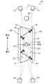
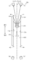
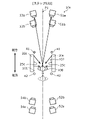
- FIG. 3 is a schematic diagram of the photographing apparatus according to Embodiment 1 as viewed from above.
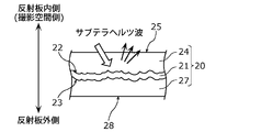
- FIG. 4 is a schematic diagram showing the cross-sectional structure of the reflector according to the first embodiment.
- FIG. 5A is a schematic diagram showing an example when the first light source according to Embodiment 1 is viewed from the front.
- 5B is a schematic diagram showing another example when the first light source according to Embodiment 1 is viewed from the front.
- FIG. 6A is a diagram for explaining an operation example of the imaging device according to Embodiment 1.
- FIG. 6B is a diagram for explaining an operation example of the imaging device according to Embodiment 1.
- FIG. 6C is a diagram for explaining an operation example of the imaging device according to Embodiment 1.
- FIG. 6D is a diagram for explaining an operation example of the imaging device according to Embodiment 1.
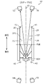
- FIG. 7 is a schematic diagram of the photographing device according to Modification 1 of Embodiment 1 as viewed from above.
- 8A is a diagram for explaining an operation example of an imaging device according to Modification 1 of Embodiment 1.
- FIG. 8B is a diagram for explaining an operation example of the imaging device according to Modification 1 of Embodiment 1.
- FIG. 8C is a diagram for explaining an operation example of the imaging device according to Modification 1 of Embodiment 1.
- FIG. 8A is a diagram for explaining an operation example of an imaging device according to Modification 1 of Embodiment 1.
- FIG. 8B is a diagram for explaining an operation example of the imaging device according to Modification 1 of Embodi
- FIG. 8D is a diagram for explaining an operation example of the imaging device according to Modification 1 of Embodiment 1.
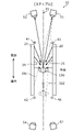
- FIG. FIG. 9 is a schematic diagram of an imaging device according to Modification 2 of Embodiment 1 as viewed from above.
- 10A is a diagram for explaining an operation example of an imaging device according to Modification 2 of Embodiment 1.
- FIG. 10B is a diagram for explaining an operation example of the imaging device according to Modification 2 of Embodiment 1.
- FIG. FIG. 11 is a schematic diagram of an imaging device according to Modification 3 of Embodiment 1 as viewed from above.
- 12A is a diagram for explaining an operation example of an imaging device according to Modification 3 of Embodiment 1.
- FIG. 12B is a diagram for explaining an operation example of the imaging device according to Modification 3 of Embodiment 1.
- FIG. 12C is a diagram for explaining an operation example of the imaging device according to Modification 3 of Embodiment 1.
- FIG. 12D is a diagram for explaining an operation example of the imaging device according to Modification 3 of Embodiment 1.
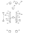
- FIG. 13 is a schematic diagram of the photographing device according to Embodiment 2 as viewed from above.
- FIG. 14 is a plan view showing how the first detector and the second detector according to the second embodiment receive reflected waves from the second point.
- 15 is a schematic diagram showing the relationship between the range in which the first detector and the second detector according to Embodiment 2 can receive the reflected wave from the second point and the angle ⁇ ; FIG. .
- FIG. 16 is a schematic diagram showing how a person walks when viewed from above.
- FIG. 17 is a plan view showing how the third detector and the fourth detector according to Embodiment 2 receive the reflected wave from the fourth point.
- FIG. 18 is a schematic diagram showing how a first detector and a second detector according to Embodiment 2 receive sub-terahertz waves diffusely reflected by the second portion and the first portion, respectively.
- FIG. 19A is a schematic diagram of an imaging device including a lens according to Embodiment 2 as viewed from above.
- FIG. 19B is a schematic diagram of the photographing apparatus having the suppressing body according to Embodiment 2 as viewed from above.
- FIG. 19C is a schematic diagram of an imaging device including a directional antenna according to Embodiment 2 as viewed from above.
- FIG. 20 is a schematic diagram of a reflector according to a modification as viewed from the front.
- An imaging apparatus includes a reflector that covers an imaging space on a passage through which an object to be photographed passes from both sides of the passage, diffusely reflects subterahertz waves, and a subterahertz wave and a sub-terahertz wave diffusely reflected by the reflector after being emitted from the first light source or the second light source.
- a first detector and a second detector that receive a reflected wave from the imaging object existing in the first inspection space and generate an image based on the received reflected wave; , a first portion positioned on one of both sides of the passage and a second portion positioned on the other of both sides of the passage, wherein the first light source, the second light source, the The first detector and the second detector are positioned on the first direction side with respect to the center of the imaging space in the direction in which the passage extends, and the first light source and the second light source are arranged in the In a plan view of the passage, they are positioned on both sides of the center line between the first portion and the second portion, and the first detector and the second detector are arranged in a plan view of the passage.
- the positional relationship between the reflector and the first inspection space is such that a first point closest to the first direction side of the first portion and a point closest to the center line in the first inspection space
- the angle between the line segment connecting the second points on the first direction side and the center line is ⁇ w1
- the angle between the line segment connecting the first detector and the second point and the center line is If the angle is ⁇ c1, ⁇ 4.5° ⁇ w1 ⁇ c1 ⁇ 4.5° is satisfied.
- sub-terahertz wave means an electromagnetic wave with a frequency of 0.05 THz or more and 2 THz or less.
- the sub-terahertz wave in this specification may be an electromagnetic wave with a frequency of 0.08 THz or more and 1 THz or less.
- diffuse reflection means that sub-terahertz waves incident on a reflector at one incident angle from a macroscopic point of view are reflected by a plurality of microscopic irregularities due to the structure of an uneven surface having a plurality of microscopic irregularities. It means that it is reflected at the angle of reflection.
- the positional relationship among the first detector, the second detector, the reflector, and the first examination space allows the torso portion of a person walking in the first examination space, , the occurrence of blind spots in receiving reflected waves from dangerous objects such as knives hidden in the body portion is suppressed.
- the positional relationship among the first detector, the reflector, and the first inspection space in a plan view of the passage may further satisfy ⁇ w1 ⁇ c1.
- first portion and the second portion are substantially parallel to each other in a plan view of the passage, and are positioned substantially line symmetrically with respect to each other with respect to the center line.
- the first light source and the second light source are positioned substantially line-symmetrically with respect to each other with respect to the center line in a plan view of the passage, and the first detector and the second detector are arranged in the In a plan view of the passages, they may be positioned substantially symmetrically with respect to the center line.
- a third light source and a fourth light source that emit sub-terahertz waves to the reflector, and after being emitted from the third light source or the fourth light source, the sub-terahertz waves are diffusely reflected by the reflector.
- the third light source and the fourth light source are located on both sides of the center line across the center line in plan view of the passage.
- the third detector and the fourth detector are positioned on both sides of the center line across the center line in a plan view of the passage, and the third light source and the third detector is located on the one side, and the positional relationship among the third detector, the reflector, and the second inspection space in a plan view of the passage is such that the first portion is closest to the second inspection space.
- the positional relationship among the third light source, the third detector, the reflector, and the second inspection space in plan view of the passage may further satisfy ⁇ w2 ⁇ c2.
- the third light source and the fourth light source are positioned substantially line-symmetrically with respect to each other with respect to the center line in plan view of the passage
- the third detector and the fourth detector The vessels may be positioned substantially line-symmetrically with respect to each other with the center line as the axis of symmetry in plan view of the passage.
- Dc the distance in the direction in which the passage extends between the point closest to the first direction side of the first inspection space in the plan view of the passage and the first detector
- Dw the width of the reflector
- Dc/Ww the energy reflected from the unit area unit solid angle in the direction of arctan (Dc/Ww) formed by the direction perpendicular to the direction in which the passage extends
- the first detector in the region in which the sub-terahertz wave is diffusely reflected in the reflecting plate is larger than the distance between the first detector and the object to be photographed in the direction in which the passage extends.
- the energy of the sub-terahertz wave diffusely reflected toward the first detector from the first region located far from the .
- the photographing apparatus having the above configuration, it is possible to suppress difficulty in distinguishing the photographed object due to reflection of the sub-terahertz wave from the first region in the image generated by the first detector. can be done.
- a suppression member may be further provided for suppressing direct penetration of the sub-terahertz waves emitted from the first light source and the second light source into the first inspection space.
- the sub-terahertz waves emitted from the first light source and the second light source are prevented from being diffused and reflected by the reflecting plate and directly applied to the imaging object present in the first inspection space. be.
- the directly irradiated sub-terahertz wave is suppressed from being received by the first detector or the second detector as a reflected wave by the object to be imaged existing in the first inspection space. can be done.
- the suppressing member may include a lens that narrows the light distribution of the sub-terahertz wave emitted from the first light source.
- the sub-terahertz waves emitted from the first light source and the second light source are irradiated directly onto the imaging object existing in the first inspection space without being diffusely reflected by the reflector using the lens. can be suppressed.
- the suppressing member may include a suppressing body that suppresses transmission of the terahertz wave emitted from the first light source.
- the sub-terahertz waves emitted from the first light source and the second light source are irradiated directly onto the imaging object existing in the first inspection space without being diffusely reflected by the reflector using the suppressor. can be suppressed.
- the suppressing member may include a directional antenna that narrows the distribution of sub-terahertz waves emitted from the first light source.
- the sub-terahertz waves emitted from the first light source and the second light source are not diffused and reflected by the reflector and are directly directed to the object to be photographed existing in the first inspection space. Irradiation can be suppressed.
- each figure is not necessarily a strict illustration.
- substantially the same configurations are denoted by the same reference numerals, and overlapping descriptions are omitted or simplified.
- FIG. 1 is a schematic diagram showing the appearance of an imaging device 10 according to the first embodiment. Components other than the reflector 20 are omitted in FIG.
- the imaging device 10 irradiates the person 100 with sub-terahertz waves when the person 100 passes through the imaging space 102 on the passage 101 sandwiched between the reflectors 20, for example.
- the imaging space 102 is a space covered by the reflector 20 in the space above the passage 101 .
- the photographing device 10 photographs, for example, a dangerous object such as a knife that the person 100 hides under his/her clothes.
- the person 100 and a dangerous object such as a knife that the person 100 hides under his or her clothes are examples of objects to be photographed.
- FIG. 2 is a block diagram showing the configuration of the imaging device 10 according to the first embodiment.
- FIG. 3 is a schematic diagram of the photographing apparatus 10 according to the first embodiment as viewed from above.
- FIG. 3 shows how the person 100 passes through the imaging space 102 .
- an example of the course of the sub-terahertz waves emitted from the first light source 41 and the second light source 42 is indicated by arrows.
- the imaging device 10 includes a reflector 20, a first light source 41, a second light source 42, a first detector 51, a second detector 52, a third detector 53, a fourth detector 54, It includes a light source control section 60 , an imaging control section 70 , a sensor 80 and an image processing section 90 .
- the 1st light source 41 and the 2nd light source 42 may be generically called simply a "light source.”
- the first detector 51, the second detector 52, the third detector 53, and the fourth detector 54 may be collectively referred to simply as "detectors.”
- the reflector 20 covers the space above the passage 101 through which the person 100 passes, specifically the imaging space 102 from at least one of both sides of the passage 101 .
- Covering from at least one of both sides of the passage 101 specifically means covering from at least one of two directions perpendicular to both sides when the passage 101 is viewed from above, that is, the direction in which the passage 101 extends.
- the reflector 20 sandwiches the photographing space 102 on the passage 101 through which the person 100 passes from both sides of the passage 101 . That is, the reflector 20 covers the imaging space 102 from both sides of the passage 101 .
- the imaging space 102 is, for example, a space sandwiched between inner surfaces (inner side surfaces 25 described later) of the reflector 20 in the space above the passage 101 .
- a pair of reflectors 20 stand upright from the floor on both sides of passage 101 and face each other. That is, the pair of reflectors 20 made up of two sheets are arranged so as to have a positional relationship that sandwiches the passage 101 when viewed from above. Also, in the illustrated example, the pair of reflectors 20 are arranged so as to have a parallel positional relationship. In the illustrated example, the pair of reflectors 20 are erected perpendicularly to the floor on which the passage 101 is provided. The height of the upper end of the reflector 20 from the passage 101 is not particularly limited, but is, for example, 1.5 m or more and 5.0 m or less.
- the shape of the reflector 20 when viewed from the direction in which the path 101 extends is two I-shapes in the case of a pair of reflectors 20, but the shape is not particularly limited.
- the reflectors 20 may be placed on at least one of the two sides of the photographing space 102, and the reflectors 20 have an I-shape and a J-shape when viewed from the direction in which the path 101 extends. It may be letter-shaped, L-shaped, U-shaped, C-shaped, frame-shaped, annular, or the like.
- the imaging device 10 may further include a reflector other than the pair of reflectors 20, or may include one reflector having a shape in which the ends of the pair of reflectors 20 are extended and connected. . Note that the imaging device 10 may include at least one reflector 20 , and may include only one of the pair of reflectors 20 , for example.
- Each of the pair of reflectors 20 has a plate shape.
- Each of the pair of reflectors 20 has an inner surface 25 and an outer surface 28 as two surfaces that are front surfaces when viewed from the thickness direction of the reflectors 20 .
- the pair of reflectors 20 are arranged such that one inner side surface 25 of the pair of reflectors 20 and the other inner side surface 25 of the pair of reflectors 20 face each other.
- the inner surface 25 is the surface of the reflecting plate 20 on the shooting space 102 side.
- each of the pair of reflectors 20 is a flat plate having an inner surface 25 and an outer surface 28 parallel to the inner surface 25 . That is, the thickness of the reflector 20 is uniform.
- the planar view shape of the pair of reflectors 20 is not particularly limited, for example, each of them is a rectangle.
- the reflector 20 diffusely reflects the sub-terahertz wave. Specifically, the reflector 20 diffusely reflects at least sub-terahertz waves incident from the imaging space 102 side (that is, from inside the pair of reflectors 20). The reflector 20 is positioned between the first light source 41 and the second light source 42 . The sub-terahertz waves emitted from the first light source 41 and the second light source 42 are diffusely reflected one or more times by at least one of the pair of reflectors 20 and irradiated to the person 100, as shown in FIG.
- the sub-terahertz waves incident on the imaging space 102 are likely to remain, and the sub-terahertz waves are projected onto the person 100 from various angles. is irradiated.
- the photographing device 10 can be made thinner and more compact than when a member such as a spherical mirror that concentrates the subterahertz waves on the person 100 is used to reflect the subterahertz waves. is possible.
- FIG. 4 is a schematic diagram showing the cross-sectional structure of the reflector 20. As shown in FIG. FIG. 4 is an enlarged view of a part of the cross section of the reflector 20. As shown in FIG. In FIG. 4, oblique hatching indicating a cross section is omitted for the sake of clarity.
- the reflector 20 has a reflective member 21 and two covering members 24 and 27 .
- the reflector 20 has a structure in which a covering member 24, a reflecting member 21, and a covering member 27 are laminated in this order from the photographing space 102 side.
- the reflecting member 21 is a sheet-like member that diffusely reflects sub-terahertz waves. Reflective member 21 is positioned between covering member 24 and covering member 27 .
- the reflecting member 21 has two main surfaces 22 and 23 as two front surfaces when viewed from the thickness direction of the reflecting member 21 .
- the main surface 22 and the main surface 23 are uneven surfaces that diffusely reflect sub-terahertz waves.
- the main surface 22 is positioned on the imaging space 102 side of the reflecting member 21
- the main surface 23 is positioned on the opposite side of the reflecting member 21 from the imaging space 102 side. Both of the two main surfaces 22 and 23 of the reflecting member 21 are covered with a covering member 24 and a covering member 27, respectively.
- the main surface 22 of the reflecting member 21 on the photographing space 102 side is covered with a covering member 24
- the main surface 23 of the reflecting member 21 on the side opposite to the photographing space 102 side is covered with a covering member 27 . ing. Therefore, the main surface 22 and the main surface 23 do not constitute the surface of the reflector 20 and are not exposed. As a result, when the main surfaces 22 and 23, which are uneven surfaces, are exposed, the uneven surfaces may come into contact with the person 100.
- the reflecting member 21 is protected by being covered with 27 .
- the average length RSm of the roughness curve element is equal to or longer than the wavelength of the sub-terahertz waves emitted from the first light source 41 and the second light source 42.
- the average length RSm of the roughness curve element is 0.15 mm or more, and may be 0.3 mm or more.
- the sub-terahertz waves are efficiently diffusely reflected by the main surfaces 22 and 23 .
- the uneven shapes of the main surface 22 and the main surface 23 are the same.
- corrugated shape of the main surface 22 and the main surface 23 may differ.
- the main surface 22 of the reflecting member 21 on the photographing space 102 side may be an uneven surface, and the main surface 23 may be a flat surface.
- the reflecting member 21 is made of a conductive member such as metal or conductive oxide.
- metals include pure metals (single metals) and alloys containing at least one metal such as copper, aluminum, nickel, iron, stainless steel, silver, gold or platinum.
- conductive oxides include ITO (Indium Tin Oxide), IZO (InZnO; Indium Zinc Oxide), AZO (AlZnO: Aluminum Zinc Oxide), FTO (Florine-doped Tin Oxide), SnO 2 , TiO 2 and ZnO. 2 and other transparent conductive oxides.
- the covering member 24 and the covering member 27 each transmit sub-terahertz waves.
- the covering member 24 and the covering member 27 each transmit, for example, 50% or more of the sub-terahertz waves incident from the thickness direction of the reflector 20 .
- Each of the covering member 24 and the covering member 27 may transmit 80% or more of the sub-terahertz wave incident from the thickness direction of the reflector 20, or may transmit 90% or more.
- the covering member 24 is positioned on the photographing space 102 side of the reflecting member 21 and covers the main surface 22 .
- the surface of the covering member 24 located on the side opposite to the reflecting member 21 side of the covering member 24 constitutes the inner surface 25 of the reflecting plate 20 .
- the inner side surface 25 is a flat surface that does not have an uneven shape like the main surface 22 . As a result, even when the person 100 passing through the passage 101 collides with the inner surface 25 of the reflector 20, the person 100 is prevented from colliding with the uneven surface (that is, the main surface 22) of the reflecting member 21. Main surface 22 is protected. Further, since the inner surface 25 of the reflector 20 is a flat surface, the reflector 20 can be easily cleaned.
- the covering member 27 is located on the opposite side of the reflecting member 21 from the imaging space 102 side and covers the main surface 23 .
- a surface of the covering member 27 located on the side opposite to the reflecting member 21 side of the covering member 27 constitutes an outer surface 28 of the reflecting plate 20 .
- the outer side surface 28 is a flat surface that does not have an uneven shape like the main surface 23 . This makes it easier to clean the reflecting plate 20 .
- the material of the covering member 24 and the covering member 27 may be any material that can be processed into the shape of the covering member 24 and the covering member 27 and can retain the shape.
- a resin material or the like is used as a material for the covering member 24 and the covering member 27, for example.
- the resin material may be, for example, a transparent amorphous resin material that transmits visible light, or a crystalline resin material that diffusely reflects visible light.
- the reflector 20 is formed, for example, by the following method.
- the covering member 24 is formed by molding a resin material with a mold having an uneven surface, or by machining a plate-shaped resin material to provide unevenness.
- a film is formed by vapor deposition, spraying, or the like.
- the reflecting plate 20 is obtained by coating the film-formed reflecting member 21 with the resin material of the coating member 27 by coating or hot-melt pasting.
- a metal plate as a material of the reflecting member 21 is machined to have an uneven surface, and the resin material of the coating member 24 and the coating member 27 is coated on the uneven metal plate, hot melt pasting, insert molding, or the like.
- a reflector 20 is obtained.
- the covering member 24 and the covering member 27 may be formed using a 3D printer.
- the pair of reflectors 20, for example, have the same configuration and material as each other. Note that the pair of reflectors 20 may differ in at least one of their configurations and materials.
- the first light source 41 and the second light source 42 are light sources that emit sub-terahertz waves to the reflector 20, respectively. Specifically, each of the first light source 41 and the second light source 42 emits sub-terahertz waves to at least one inner surface 25 of the pair of reflectors 20 . Further, as shown in FIG. 3 , the first light source 41 and the second light source 42 are arranged such that part of the sub-terahertz waves emitted by the first light source 41 and the second light source 42 are diffusely reflected by the reflector 20 a plurality of times. The two light sources 42 emit sub-terahertz waves to the reflector 20 . Also, part of the subterahertz waves emitted by the first light source 41 and the second light source 42 may be directly incident on the person 100 .
- the first light source 41 and the second light source 42 emit sub-terahertz waves under the control of the light source controller 60, for example.
- the first light source 41 and the second light source 42 may always emit subterahertz waves during use, or may emit subterahertz waves at regular time intervals.
- the first light source 41 and the second light source 42 are supported by, for example, supporting members (not shown).
- the first light source 41 and the second light source 42 are realized by, for example, a known subterahertz wave generation element and a circuit that supplies current to the subterahertz wave generation element.
- the first light source 41 is positioned forward of the center of the imaging space 102 in the direction in which the passage 101 extends.
- the center of the imaging space 102 is the center of the space formed by being sandwiched between the reflectors 20 .
- the first light source 41 is positioned forward of the reflector 20 in the direction in which the passage 101 extends.
- the front in the direction in which the passage 101 extends may be simply referred to as the "front”
- the rear in the direction in which the passage 101 extends may simply be referred to as the "rear”.
- the terms “forward” and “rearward” as used herein do not refer to the forward and backward directions of travel of the person 100 in the aisle 101 , but rather are terms that refer to relative directions.
- forward is an example of a first direction
- rearward is an example of a second direction.
- the first light source 41 emits subterahertz waves from the front side of the reflector 20 toward the inner surface 25 of the reflector 20 .
- the first light source 41 is located near the front end of each of the pair of reflectors 20 and is separated from the reflectors 20 . Also, the first light source 41 is positioned between the first detector 51 and the third detector 53 and the reflector 20 . Accordingly, the first light source 41, the first detector 51, and the third detector 53 are positioned on the same side of the reflector 20, specifically, on the front side. Also, the first light source 41 emits sub-terahertz waves to the reflector 20 from a position closer to the reflector 20 than the first detector 51 and the third detector 53 are.
- the sub-terahertz wave diffusely reflected by the reflecting plate 20 after being emitted from the first light source 41 is irradiated to the person 100 without proceeding to the first detector 51 side and the third detector 53 side. Therefore, the sub-terahertz waves emitted from the first light source 41 can be efficiently used.
- the first light source 41 may be positioned, for example, in the imaging space 102 or may be positioned in front of the first detector 51 and the third detector 53 .
- the first light source 41 includes, for example, a point light source that emits sub-terahertz waves.
- FIG. 5A is a schematic diagram showing an example when the first light source 41 is viewed from the front. Components other than the first light source 41 and the reflector 20 are omitted in FIG. 5A.
- the first light source 41 includes a plurality of point light sources 41a arranged along the reflecting plate 20 when viewed from the direction in which the passage 101 extends and emitting sub-terahertz waves.
- the plurality of point light sources 41a are arranged along the direction in which the pair of reflecting plates 20 are erected.
- FIG. 1 is a schematic diagram showing an example when the first light source 41 is viewed from the front. Components other than the first light source 41 and the reflector 20 are omitted in FIG. 5A.
- the first light source 41 includes a plurality of point light sources 41a arranged along the reflecting plate 20 when viewed from the direction in which the passage 101 extends and emitting sub-terahe
- the first light source 41 includes a pair of multiple point light sources 41a arranged along the direction in which the pair of reflecting plates 20 are erected.
- the number of the plurality of point light sources 41a arranged is not particularly limited, and may be two, or may be four or more.
- a pair of the plurality of point light sources 41a are arranged symmetrically with respect to the virtual plane P1.
- the virtual plane P1 is a vertical plane passing through the center of the imaging space 102 and along the direction in which the passage 101 extends. Note that the plurality of point light sources 41 a may be arranged only on one side of the pair of reflectors 20 .
- the first light source 41 may include another light source instead of the plurality of point light sources 41a.
- FIG. 5B is a schematic diagram showing another example when the first light source 41 is viewed from the front. Components other than the first light source 41 and the reflector 20 are omitted in FIG. 5B.
- the first light source 41 includes a linear light source 41b that extends along the reflecting plate 20 and emits sub-terahertz waves when viewed from the direction in which the passage 101 extends.
- the linear light source 41b extends along the direction in which the pair of reflecting plates 20 are erected.
- FIG. 1 is a schematic diagram showing another example when the first light source 41 is viewed from the front. Components other than the first light source 41 and the reflector 20 are omitted in FIG. 5B.
- the first light source 41 includes a linear light source 41b that extends along the reflecting plate 20 and emits sub-terahertz waves when viewed from the direction in which the passage 101 extends.
- the linear light source 41b extend
- one linear light source 41b is arranged to extend along one front side edge of the pair of reflectors 20, and one linear light source 41b is arranged to extend along the other front side edge of the pair of reflectors 20.
- the first light source 41 includes a pair of linear light sources 41b.
- the number of linear light sources 41b arranged so as to extend along the respective front end portions of the pair of reflectors 20 may be two or more.
- the pair of linear light sources 41b are arranged symmetrically with respect to the virtual plane P1. Note that the linear light source 41b may be arranged only on one side of the pair of reflectors 20 .
- the first light source 41 is arranged along the reflecting plate 20 when viewed from the direction in which the passage 101 extends. and includes at least one of the linear light sources 41b that radiate sub-terahertz waves. Thereby, the first light source 41 can emit sub-terahertz waves widely along the reflecting plate 20 when viewed from the direction in which the passage 101 extends. As a result, the person 100 is effectively irradiated with sub-terahertz waves.
- the second light source 42 is located on the rear side of the center of the imaging space 102 in the direction in which the passage 101 extends. In the example shown in FIG. 3 , the second light source 42 is located behind the reflector 20 . The second light source 42 emits subterahertz waves from behind the reflector 20 toward the inner surface 25 of the reflector 20 .
- the second light source 42 is located near the rear end of each of the pair of reflectors 20 and is separated from the reflectors 20 . Also, the second light source 42 is positioned between the second detector 52 and the fourth detector 54 and the reflector 20 .
- the second light source 42 may be positioned, for example, in the imaging space 102 or may be positioned behind the second detector 52 and the fourth detector 54 . Further, when the photographing device 10 does not photograph the image of the rear side of the person 100 , the second light source 42 may not be provided in the photographing device 10 .
- the second light source 42 includes, for example, at least one of a point light source and a line light source that emit subterahertz waves.
- the point light source and line light source included in the second light source 42 are similar to those of the first light source 41 . Therefore, the point light source and line light source included in the second light source 42 will be described by replacing the first light source 41 with the second light source 42 and reading the front with the rear from the description of FIGS. 5A and 5B.
- the first detector 51 receives the reflected wave of the sub-terahertz wave emitted from the first light source 41 and diffusely reflected by the reflector 20 by the person 100 .
- the first detector 51 generates an image based on the received reflected waves.
- the first detector 51 outputs the generated image to the image processing section 90 .
- Generating an image by a detector such as the first detector 51 is also referred to as “capturing”.
- the first detector 51 is exposed at the timing when the first light source 41 emits sub-terahertz waves to generate an image.
- the first detector 51 is positioned forward of the center of the imaging space 102 in the direction in which the passage 101 extends. In the example shown in FIG. 3, the first detector 51 is positioned forward of the reflector 20 in the direction in which the passage 101 extends. The first detector 51 captures an image of the front surface of the person 100 .
- the first detector 51 is supported by, for example, a support member (not shown) or the like.
- the first detector 51 includes an image sensor 55 and an optical system 56.
- the image sensor 55 receives sub-terahertz waves reflected by the person 100 that are diffusely reflected by the reflector 20 after being emitted from the light source such as the first light source 41 .
- the image sensor 55 detects the intensity of the received reflected waves and generates an image based on the detected intensity. Specifically, the image sensor 55 converts an image of sub-terahertz waves emitted from the object to be photographed during exposure into an electric signal corresponding to its intensity. The image sensor 55 then generates an image based on the converted electrical signal.
- the image generated by the image sensor 55 is output to the image processing section 90 .
- Sub-terahertz waves are mirror-reflected by the human body and metals, and penetrate clothes and bags. For this reason, the image sensor 55 receives the reflected wave specularly reflected by the body of the person 100 from the area included in the angular range that the image sensor 55 can receive in the body of the person 100 .
- a reflected wave from the person 100 is incident on the image sensor 55, for example, passing through a range indicated by a dashed line extending from the first detector 51 in FIG.
- the image sensor 55 receives a reflected wave mirror-reflected by the hidden knife from an area included in the angle range that the image sensor 55 can receive.
- the image sensor 55 is composed of, for example, a plurality of pixels each including a subterahertz wave detection element, peripheral circuits, and the like.
- the optical system 56 forms an image on the image sensor 55 of the sub-terahertz wave that is diffusely reflected by the reflector 20 after being emitted from the light source such as the first light source 41 and reflected by the person 100 .
- the optical system 56 includes, for example, at least one lens. Note that the first detector 51 may not include the optical system 56 and the reflected wave may directly enter the image sensor 55 .
- the second detector 52 receives the reflected wave of the sub-terahertz wave emitted from the second light source 42 and diffusely reflected by the reflector 20 by the person 100 .
- the second detector 52 generates an image based on the received reflected waves.
- the second detector 52 outputs the generated image to the image processing section 90 .
- the second detector 52 is exposed at the timing when the second light source 42 emits sub-terahertz waves to generate an image.
- the second detector 52 is located on the rear side of the center of the imaging space 102 in the direction in which the passage 101 extends. In the example shown in FIG. 3 , the second detector 52 is located behind the reflector 20 . The second detector 52 captures an image of the rear surface of the person 100 .
- the second detector 52 is supported by, for example, a support member (not shown) or the like. In this way, by including the first detector 51 and the second detector 52 in the photographing device 10, images of both the front and rear sides of the person 100 can be generated.
- the second detector 52 includes an image sensor 55a and an optical system 56a. Since the image sensor 55a and the optical system 56a are the same as the image sensor 55 and the optical system 56 described above, detailed description thereof will be omitted.
- the second detector 52 may not be provided in the imaging device 10 when the imaging device 10 does not capture an image of the rear surface of the person 100 .
- the third detector 53 receives the reflected wave of the sub-terahertz wave emitted from the first light source 41 and diffusely reflected by the reflector 20 by the person 100 .
- the third detector 53 generates an image based on the received reflected waves.
- the third detector 53 outputs the generated image to the image processing section 90 .
- the third detector 53 is exposed at the timing when the first light source 41 emits sub-terahertz waves to generate an image.
- the third detector 53 is positioned forward of the center of the imaging space 102 in the direction in which the passage 101 extends. In the example shown in FIG. 3 , the third detector 53 is located forward of the reflector 20 .
- the third detector 53 is supported by, for example, a support member (not shown) or the like.
- the first detector 51 and the third detector 53 are arranged at different positions with respect to the passage 101 when viewed from above.
- the first detector 51 and the third detector 53 have different incident directions of reflected waves from the person 100 .
- the first detector 51 and the third detector 53 generate images based on reflected waves from surfaces of the person 100 facing in different directions. Therefore, for example, blind spots can be reduced when a dangerous object such as a knife hidden by the person 100 is detected by the photographing device 10 .
- the first detector 51 and the third detector 53 have a symmetrical positional relationship with respect to the virtual plane P1. Therefore, the incident direction of the reflected wave on the first detector 51 and the incident direction of the reflected wave on the third detector 53 are symmetrical with respect to the virtual plane P1.
- the first detector 51 and the third detector 53 are arranged along the direction perpendicular to the direction in which the passage 101 extends in a top view of the passage 101 .
- the third detector 53 includes an image sensor 55b and an optical system 56b. Since the image sensor 55b and the optical system 56b are the same as the image sensor 55 and the optical system 56 described above, detailed description thereof will be omitted.
- the fourth detector 54 receives the reflected wave of the sub-terahertz wave emitted from the second light source 42 and diffusely reflected by the reflector 20 by the person 100 .
- the fourth detector 54 generates an image based on the received reflected waves.
- the fourth detector 54 outputs the generated image to the image processing section 90 .
- the fourth detector 54 is exposed at the timing when the second light source 42 emits sub-terahertz waves to generate an image.
- the fourth detector 54 is located on the rear side of the center of the imaging space 102 in the direction in which the passage 101 extends. In the example shown in FIG. 3 , the fourth detector 54 is located behind the reflector 20 .
- the fourth detector 54 is supported by, for example, a support member (not shown) or the like.
- the positional relationship between the second detector 52 and the fourth detector 54 is the same as the positional relationship between the first detector 51 and the third detector 53 .
- the first detector 51 in the description of the positional relationship between the first detector 51 and the third detector 53 is read as the second detector, and the third detector 51 is replaced with the second detector. The description will be made by replacing the detector 53 with the fourth detector 54 .
- the fourth detector 54 includes an image sensor 55c and an optical system 56c. Since the image sensor 55c and the optical system 56c are the same as the image sensor 55 and the optical system 56 described above, detailed description thereof will be omitted.
- At least one of the third detector 53 and the fourth detector 54 may not be provided in the imaging device 10 .
- the light source control unit 60 controls emission of sub-terahertz waves from each of the first light source 41 and the second light source 42 .
- the light source control unit 60 controls, for example, the timing of emitting sub-terahertz waves to each of the first light source 41 and the second light source 42 .
- the light source control unit 60 causes the first light source 41 to emit subterahertz waves during a first period and does not cause the second light source 42 to emit subterahertz waves, and causes the second light source to emit subterahertz waves during a second period different from the first period. 42 is caused to emit subterahertz waves and the first light source 41 is not caused to emit subterahertz waves.
- the light source control unit 60 controls emission of sub-terahertz waves from the first light source 41 and the second light source 42, for example, based on signals acquired from the imaging control unit 70, the sensor 80, and the like.
- the light source control unit 60 includes, for example, a processor and memory, and is implemented by the processor executing a program stored in the memory.
- the imaging control unit 70 controls the timing at which each detector generates an image. For example, the imaging control unit 70 causes the first detector 51 and the third detector 53 to synchronously generate images, and the second detector 52 and the fourth detector 54 to synchronously generate images. Let In addition, the imaging control unit 70 causes each detector to generate an image, for example, based on the emission timing of the sub-terahertz waves from the first light source 41 and the second light source 42 . The imaging control unit 70 may cause each detector to generate an image based on a signal from the sensor 80 or the like.
- the imaging control unit 70 includes, for example, a processor and memory, and is implemented by the processor executing a program stored in the memory.
- the sensor 80 is a sensor for detecting the presence of the person 100.
- the sensor 80 outputs, for example, a signal indicating the presence of the person 100 to the light source control section 60 and the photographing control section 70 .
- the sensor 80 is, for example, a camera that captures moving images.
- the sensor 80 may be another sensor such as a human sensor. Further, although the number of sensors 80 provided in the photographing device 10 is one in the example shown in FIG. 3, the photographing device 10 may include a plurality of sensors 80.
- the image processing unit 90 Upon receiving an image from each detector, the image processing unit 90 outputs the received image to the outside, performs image processing on the received image, and outputs the result of the image processing to the outside.
- the image processing performed by the image processing unit 90 includes, for example, determining whether an object having a predetermined characteristic (for example, an object having a characteristic of a blade) is included in the image output from the detector, When it is determined that an object having a characteristic is included, processing may be performed to output a predetermined detection signal (for example, an alarm indicating that an object having a characteristic of a knife is being photographed). Further, the image processing section 90 may perform synthesis processing on the images received from each detector.
- the image processing unit 90 includes, for example, a processor and memory, and is implemented by the processor executing a program stored in the memory.
- the imaging device 10 may not include the image processing unit 90, and the detector may output an image to an external image processing device. Also, the function of the image processing section 90 may be provided in each detector.
- the irradiation mode of subterahertz waves in the imaging device 10 according to the first embodiment will be described with reference to FIG.
- the subterahertz wave (arrow in FIG. 3) emitted from the light source to the reflector 20 is diffusely reflected by the reflector 20 because the imaging space 102 is covered with the reflector 20 from the side of the imaging space 102. incident on the person 100.
- the inner surface 25 of the reflector 20 functions as a surface light source, and the person 100 is irradiated with sub-terahertz waves from various angles over a relatively wide range. Therefore, the imaging device 10 can effectively irradiate the person 100 with sub-terahertz waves.
- the sub-terahertz wave emitted from the light source is diffusely reflected by the reflectors 20 one or more times. 100.
- most of the sub-terahertz waves emitted from the light source to the reflector 20 are repeatedly diffusely reflected in the imaging space 102, so they remain in the imaging space 102 located on the passage 101 through which the person 100 passes.
- the imaging device 10 can more effectively irradiate the person 100 with sub-terahertz waves.
- the reflected waves of the subterahertz waves reflected over a relatively wide range of the person 100 enter the detector.
- the sub-terahertz waves emitted from the light source to the reflector 20 tend to remain in the imaging space 102, the amount of reflected waves entering the detector increases. Therefore, the quality of the image generated by the detector is improved. As a result, for example, detection accuracy is improved when the photographing device 10 is used to detect a dangerous object such as a knife hidden by the person 100 .
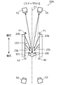
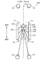
- 6A, 6B, 6C, and 6D are diagrams for explaining an operation example of the imaging device 10 according to the first embodiment.
- 6A, 6B, 6C, and 6D show diagrams of the imaging device 10 viewed from above.
- illustration of the sensor 80 is omitted in FIGS. 6A, 6B, 6C and 6D.
- the first light source 41 and the second light source 42 are hatched with dots when they emit subterahertz waves. Dots are not hatched if they are not.
- examples of paths of sub-terahertz waves emitted from the reflector 20 are schematically indicated by solid-line arrows. These are the same in the diagrams for explaining the operation examples in the following modified examples.
- step S1 the person 100 enters the imaging space 102 and passes through the rear end of the imaging space 102 .
- the light source control unit 60 detects that the person 100 exists at the rear end of the imaging space 102, the light source control unit 60 causes the first light source 41 to emit sub-terahertz waves.
- the light source control unit 60 detects the presence of the person 100 by receiving, from the sensor 80, a signal indicating that the person 100 is present at the rear end of the imaging space 102, for example. Also, at this time, the light source control unit 60 does not cause the second light source 42 to emit sub-terahertz waves.
- the sub-terahertz wave emitted from the first light source 41 is diffusely reflected by the reflector 20 one or more times and is irradiated from the inner surface 25 to the person 100 .
- the person 100 is irradiated with sub-terahertz waves emitted from the inner surface 25 located on the front side of the person 100 .
- a reflected wave of the subterahertz wave irradiated to the person 100 by the person 100 enters the first detector 51 .
- the first detector 51 receives waves reflected by the person 100 .
- the imaging control unit 70 causes the first detector 51 to display an image based on the reflected waves received by the first detector 51 at the timing when the light source control unit 60 causes the first light source 41 to emit sub-terahertz waves. generate.
- the first detector 51 generates an image based on the reflected wave from the person 100 passing through the rear end of the imaging space 102 . Thereby, the first detector 51 generates an image of the front surface of the person 100 .
- the first detector 51 outputs the generated image to the image processing section 90 .
- the light source control unit 60 detects that the first detector 51 has completed generating an image, and turns off the first light source 41 .
- step S1 the first detector 51 receives waves during a first period, which is a period during which the light source control unit 60 causes the first light source 41 to emit subterahertz waves and does not cause the second light source 42 to emit subterahertz waves.
- An image is generated based on the waves reflected by the person 100 . If the second light source 42 emits subterahertz waves when the first detector 51 generates an image, the subterahertz waves emitted from the second light source 42 located behind the person 100 are The wave reflected by the person 100 may enter the first detector 51 at the same time. Therefore, the image generated by the first detector 51 due to the reflected wave from the person 100 may become unclear.
- step S1 the first detector 51 generates an image based on the reflected wave from the person 100 received during the first period in which the second light source 42 does not emit subterahertz waves.
- the image of the wave reflected by the person 100 is clear.
- step S2 the person 100 moves forward from the position in step S1 and is positioned in the center of the imaging space 102 in the direction in which the passage 101 extends.
- the light source control unit 60 detects that the person 100 exists in the central portion of the imaging space 102, the light source control unit 60 causes the first light source 41 to emit sub-terahertz waves.
- the light source control unit 60 detects the presence of the person 100 by receiving from the sensor 80 a signal indicating that the person 100 is present in the central portion of the imaging space 102 in the direction in which the passage 101 extends. detect. Also, at this time, the light source control unit 60 does not cause the second light source 42 to emit sub-terahertz waves.
- the light source control unit 60 instead of detecting the presence of the person 100, the light source control unit 60 causes the first light source 41 to emit sub-terahertz waves after a predetermined time has elapsed since the generation of the image by the first detector 51 in step S1. good too.
- the predetermined time is set, for example, to a time during which the person 100 takes about one or two steps.
- the sub-terahertz wave emitted from the first light source 41 is diffusely reflected by the reflector 20 one or more times and is irradiated from the inner surface 25 to the person 100 .
- a reflected wave of the subterahertz wave irradiated to the person 100 by the person 100 enters the first detector 51 .
- the first detector 51 receives waves reflected by the person 100 .
- the imaging control unit 70 causes the first detector 51 to display an image based on the reflected waves received by the first detector 51 at the timing when the light source control unit 60 causes the first light source 41 to emit sub-terahertz waves. generate. Thereby, the first detector 51 generates an image of the front surface of the person 100 .
- the first detector 51 outputs the generated image to the image processing section 90 .
- the light source control unit 60 detects that the first detector 51 has completed generating an image, and turns off the first light source 41 .
- the first detector 51 receives reflected waves from the person 100 at a plurality of timings while the person 100 passes through the imaging space 102 .
- the first detector 51 then generates a plurality of images based on the received reflected waves.
- images of a plurality of aspects of the person 100 are generated. Therefore, for example, an image including a portion that was not captured in one image is generated, and detection accuracy and the like can be improved when the imaging device 10 is used to detect a dangerous object or the like hidden by the person 100 .
- step S2 similarly to step S1, the first detector 51 generates an image based on the reflected wave received by the person 100 during the first period. Further, in step S2, the range where the reflected wave from the person 100 is incident on the first detector 51 is the range indicated by the dashed line extending from the first detector 51 in FIG. 6B.
- the light source 42 and part of the reflector 20 are located. Therefore, when the second light source 42 emits subterahertz waves, the subterahertz waves originating from the second light source 42 are particularly likely to enter the first detector 51 . Therefore, the first detector 51 generates an image during the first period in which the second light source 42 does not emit sub-terahertz waves, so that the image of the reflected waves from the person 100 becomes clear.
- step S1 the light source control unit 60 causes the first light source 41 to emit sub-terahertz waves until the generation of the image of the first detector 51 in step 2 is completed without turning off the first light source 41. You can leave it alone. In this case, for example, when the imaging control unit 70 detects that the person 100 exists in the center of the imaging space 102, it causes the first detector 51 to generate an image.
- step S3 the light source control unit 60 causes the second light source 42 to emit sub-terahertz waves, as shown in FIG. 6C.
- the light source control unit 60 causes the second light source 42 to emit sub-terahertz waves immediately after the completion of the exposure in the generation of the image by the first detector 51 in step S2.
- the light source control unit 60 acquires, for example, a signal indicating the timing at which the first detector 51 finishes generating an image via the imaging control unit 70 .
- the signal is, for example, a signal indicating the end of exposure of the image sensor 55 .
- the light source control unit 60 does not cause the first light source 41 to emit sub-terahertz waves.
- the sub-terahertz wave emitted from the second light source 42 is diffusely reflected by the reflector 20 one or more times and is irradiated to the person 100 from the inner surface 25 .
- the person 100 is irradiated with sub-terahertz waves emitted from the inner surface 25 located on the rear side of the person 100 .
- a reflected wave of the subterahertz wave irradiated to the person 100 by the person 100 is incident on the second detector 52 .
- the second detector 52 receives waves reflected by the person 100 .
- the imaging control unit 70 activates the second detector. 52 to start generating the image.
- the second detector 52 detects the wave reflected by the person 100 immediately after the completion of the exposure in the generation of the image based on the wave reflected by the person 100 received by the first detector 51 in step S2. start the exposure in generating the image.
- the second detector 52 captures an image of the rear surface of the person 100 immediately after the first detector 51 captures the image in step S2.
- the second detector 52 outputs the generated image to the image processing section 90 .
- the light source control unit 60 detects completion of image generation by the second detector 52 and turns off the second light source 42 .
- steps S2 and S3 imaging by the first detector 51 and imaging by the second detector 52 are performed without a time interval.
- the person 100 can be photographed from both the front and rear sides without a time interval, the area of the body of the person 100 that is not photographed during photographing is reduced, and the photographing device 10 is used to detect dangerous objects or the like hidden by the person 100. can improve the detection accuracy of
- step S3 the second detector 52 received waves during a second period during which the light source control unit 60 causes the second light source 42 to emit subterahertz waves and does not cause the first light source 41 to emit subterahertz waves.
- An image is generated based on the waves reflected by the person 100 . If the first light source 41 emits subterahertz waves when the second detector 52 generates an image, the subterahertz waves emitted from the first light source 41 positioned in front of the person 100 are It may enter the second detector 52 at the same time as the reflected wave from the person 100 . Therefore, the image generated by the second detector 52 due to the reflected wave from the person 100 may become unclear.
- step S3 the second detector 52 generates an image based on the reflected wave from the person 100 received during the second period in which the first light source 41 does not emit subterahertz waves.
- the image of the reflected wave from the person 100 becomes clear.
- step S3 the range where the reflected wave from the person 100 is incident on the second detector 52 is the range indicated by the dashed line extending from the second detector 52 in FIG. 6C.
- the light source 41 and part of the reflector 20 are located. Therefore, when the second light source 42 emits subterahertz waves, the subterahertz waves originating from the first light source 41 are particularly likely to enter the second detector 52 . Therefore, the second detector 52 generates an image during the second period in which the first light source 41 does not emit sub-terahertz waves, so that the image reflected by the person 100 becomes clear.
- the detector that first generates an image may be the second detector 52 instead of the first detector 51. That is, in the description of steps S2 and S3, the first light source 41 and the second light source 42 may be interchanged, and the first detector 51 and the second detector 52 may be interchanged.
- step S4 the person 100 moves forward from the position in step S3 and is positioned at the front end of the imaging space 102 . That is, the person 100 passes through the front end of the imaging space 102 .
- the light source control unit 60 detects that the person 100 exists at the front end of the imaging space 102, the light source control unit 60 causes the second light source 42 to emit sub-terahertz waves.
- the light source control unit 60 detects the presence of the person 100 by, for example, receiving from the sensor 80 a signal indicating that the person 100 is present at the front end of the imaging space 102 . Also, at this time, the light source control unit 60 does not cause the first light source 41 to emit sub-terahertz waves.
- the sub-terahertz wave emitted from the second light source 42 is diffusely reflected by the reflector 20 one or more times and is irradiated to the person 100 from the inner surface 25 .
- a reflected wave of the subterahertz wave irradiated to the person 100 by the person 100 is incident on the second detector 52 .
- the second detector 52 receives waves reflected by the person 100 .
- the imaging control unit 70 causes the second detector 52 to generate an image based on the reflected waves received by the second detector 52 at the timing when the light source control unit 60 causes the second light source 42 to emit subterahertz waves. Let That is, the second detector 52 generates an image based on reflected waves from the person 100 passing through the front end of the imaging space 102 .
- the second detector 52 captures an image of the rear surface of the person 100 .
- the second detector 52 outputs the generated image to the image processing section 90 .
- the light source control unit 60 detects completion of image generation by the second detector 52 and turns off the second light source 42 .
- the second detector 52 receives reflected waves from the person 100 at a plurality of timings while the person 100 passes through the imaging space 102 .
- the second detector 52 then generates a plurality of images based on the received reflected waves.
- step S4 similarly to step S3, the second detector 52 generates an image based on the reflected wave received by the person 100 during the second period. Therefore, as in step S3, the effect of making the image of the reflected wave from the person 100 clearer is obtained.
- the imaging control unit 70 operates the first detector 51 and the third detector 53 in synchronization, and the second detector 52 and the fourth detector 54, for example. operate synchronously. That is, the third detector 53 operates similarly to the first detector 51 , and the fourth detector 54 operates similarly to the second detector 52 . Therefore, the operations of the third detector 53 and the fourth detector 54 are explained by replacing the first detector 51 with the third detector 53 and the second detector 52 . These are the same for the operation examples in the modifications described below.
- the image processing unit 90 may perform image processing for synthesizing the image generated by the first detector 51 and the image generated by the third detector 53 . Further, the image processing section 90 may perform image processing for synthesizing the image generated by the second detector 52 and the image generated by the fourth detector 54 .
- each detector generated an image of the person 100 at the positions shown in FIGS. 6A, 6B, 6C, and 6D.
- the position of the person 100 when the detector generates an image of the person 100 may be, for example, a position where the inner surface 25 can emit subterahertz waves to the person 100 from the detector side.
- the position where the person 100 is imaged in steps S2 and S3 is a position where sub-terahertz waves can be emitted to the person 100 from both the inner side surface 25 located on the front side and the rear side of the person 100. be.
- the position where the person 100 is photographed in steps S2 and S3 is, for example, the central portion of the photographing space 102 in the direction in which the passage 101 extends, as described above.
- each detector continuously generates an image, and selects the image generated at the timing from step S1 to step S4 from among the plurality of continuously generated images.
- it may be output to the image processing unit 90 .
- each detector may continuously generate an image and output all of the continuously generated multiple images to the image processing section 90 .
- the image processing unit 90 selects, for example, an image generated at the timing from step S1 to step S4 from the plurality of received images, and performs image processing on the selected image.
- the imaging device according to Modification 1 of Embodiment 1 does not leave a time interval between imaging by the first detector and imaging by the second detector. The main difference is that doing is done multiple times.
- the imaging device according to Modification 1 of Embodiment 1 has a length of the reflector in the direction in which the passage extends, and the first detector and the second detector. the distance between is increasing.
- FIG. 7 is a schematic diagram of the photographing device 10a according to this modification as viewed from above.
- the photographing device 10a is configured to include a reflecting plate 20a instead of the reflecting plate 20 of the photographing device 10.
- the photographing device 10a has the same configuration as that of the photographing device 10 except for the reflector 20a.
- the reflector 20a covers the imaging space 102 on the passage 101 through which the person 100 passes from at least one of both sides of the passage 101.
- the reflecting plate 20a sandwiches the imaging space 102 on the passage 101 through which the person 100 passes from both sides of the passage 101 .
- a pair of reflectors 20a stand upright from the floor on both sides of the passage 101 through which the person 100 passes and face each other.
- Each of the pair of reflectors 20a has an inner surface 25a and an outer surface 28a as two surfaces that are front surfaces when viewed in the thickness direction of the reflectors 20a.
- the reflector 20a has the same configuration as the reflector 20 except that it is longer than the reflector 20 in the direction in which the path 101 extends, and detailed description thereof will be omitted.
- 8A, 8B, 8C, and 8D are diagrams for explaining an operation example of the imaging device 10a according to this modification.
- step S11 the person 100 enters the imaging space 102 and passes through the imaging space 102 on the rear side.
- the light source control unit 60 detects that the person 100 exists on the rear side of the imaging space 102, the light source control unit 60 causes the first light source 41 to emit sub-terahertz waves. Also, at this time, the light source control unit 60 does not cause the second light source 42 to emit sub-terahertz waves.
- the sub-terahertz wave emitted from the first light source 41 is diffusely reflected once or more by the reflector 20a, and is irradiated to the person 100 from the inner surface 25a. Since the subsequent operation of the photographing device 10a is the same as in step S2, detailed description thereof will be omitted. As a result, the first detector 51 generates an image based on the reflected wave from the person 100 passing behind the imaging space 102 .
- step S12 the light source controller 60 causes the second light source 42 to emit sub-terahertz waves, as shown in FIG. 8B. Specifically, the light source control unit 60 causes the second light source 42 to emit sub-terahertz waves immediately after the completion of the exposure in the generation of the image by the first detector 51 in step S11. Also, at this time, the light source control unit 60 does not cause the first light source 41 to emit sub-terahertz waves.
- the sub-terahertz wave emitted from the second light source 42 is diffusely reflected once or more by the reflector 20a, and is irradiated to the person 100 from the inner surface 25a. Since the subsequent operation of the photographing device 10a is the same as in step S3, detailed description thereof will be omitted. Accordingly, the imaging control unit 70 causes the second detector 52 to start exposure for image generation immediately after the first detector 51 completes exposure for image generation in step S11. That is, the second detector 52 captures an image of the rear surface of the person 100 immediately after the first detector 51 captures the image in step S11.
- step S13 the person 100 moves forward from the position in step S12 and is positioned on the front side in the imaging space 102. That is, the person 100 is passing through the front side of the imaging space 102 .
- the light source control unit 60 detects that the person 100 exists on the front side in the imaging space 102, the light source control unit 60 causes the first light source 41 to emit sub-terahertz waves. Also, at this time, the light source control unit 60 does not cause the second light source 42 to emit sub-terahertz waves.
- the sub-terahertz wave emitted from the first light source 41 is diffusely reflected once or more by the reflector 20a, and is irradiated to the person 100 from the inner surface 25a. Since the subsequent operation of the photographing device 10a is the same as in step S2, detailed description thereof will be omitted. Thereby, the first detector 51 generates an image based on the reflected wave from the person 100 passing through the front side of the imaging space 102 .
- step S14 the light source control unit 60 causes the second light source 42 to emit sub-terahertz waves, as shown in FIG. 8D. Specifically, the light source control unit 60 causes the second light source 42 to emit sub-terahertz waves immediately after the completion of the exposure in the generation of the image by the first detector 51 in step S13.
- the sub-terahertz wave emitted from the second light source 42 is diffusely reflected once or more by the reflector 20a, and is irradiated to the person 100 from the inner surface 25a. Since the subsequent operation of the photographing device 10a is the same as in step S3, detailed description thereof will be omitted. Accordingly, the imaging control unit 70 causes the second detector 52 to start exposure for image generation immediately after the first detector 51 completes exposure for image generation in step S13. In other words, the second detector 52 captures an image of the rear surface of the person 100 immediately after the first detector 51 captures the image in step S13.
- steps S11 and S12 imaging by the first detector 51 and imaging by the second detector 52 are performed without a time interval. Also in steps S13 and S14, the imaging by the first detector 51 and the imaging by the second detector 52 are performed without a time interval.
- steps S13 and S14 the imaging by the first detector 51 and the imaging by the second detector 52 are performed without a time interval.
- steps S11 and S12 both the front and rear surfaces of the person 100 are photographed at the same position of the person 100. Therefore, in order to irradiate the person 100 with subterahertz waves equivalent to the operation example of the first embodiment, the reflectors 20a must be positioned on both front and rear sides of the person 100. As shown in FIG. The same applies to steps S13 and S14. Therefore, in order to photograph the person 100 from both the front and rear sides a plurality of times without any time interval without degrading the image quality of the photographed image, the length of the reflector 20a should be longer than that of the reflector 20. , is longer by the length of the surface for emitting the sub-terahertz wave to the person 100 .
- the imaging device according to Modification 2 of Embodiment 1 has the first detector and the second detector, respectively, where the person is positioned at one predetermined location. The main difference is that the image is captured in the case.
- the imaging device according to Modification 2 of Embodiment 1 has a length of the reflector in the direction in which the passage extends, and the first detector and the second detector. The distance between is getting shorter.
- FIG. 9 is a schematic diagram of an imaging device 10b according to this modified example viewed from above.
- the photographing device 10b is configured to include a reflecting plate 20b instead of the reflecting plate 20 of the photographing device 10.
- the photographing device 10b has the same configuration as that of the photographing device 10 except for the reflector 20b.
- the reflector 20b covers the imaging space 102 on the passage 101 through which the person 100 passes from at least one of both sides of the passage 101 .
- the reflector 20b sandwiches the imaging space 102 on the passage 101 through which the person 100 passes from both sides of the passage 101 .
- a pair of reflectors 20b stand upright from the floor on both sides of the passage 101 through which the person 100 passes and face each other.
- Each of the pair of reflectors 20b has an inner surface 25b and an outer surface 28b as two surfaces that are front surfaces when viewed in the thickness direction of the reflectors 20b.
- the reflector 20b has the same configuration as the reflector 20 except that it is shorter than the reflector 20 in the direction in which the path 101 extends, and detailed description thereof will be omitted.
- 10A and 10B are diagrams for explaining an operation example of the imaging device 10b according to this modification.
- step S21 the person 100 enters the imaging space 102 and passes through the end of the imaging space 102 on the rear side.
- the light source control unit 60 detects that the person 100 exists at the rear end of the imaging space 102, the light source control unit 60 causes the first light source 41 to emit sub-terahertz waves. Also, at this time, the light source control unit 60 does not cause the second light source 42 to emit sub-terahertz waves.
- the sub-terahertz wave emitted from the first light source 41 is diffusely reflected once or more by the reflector 20b, and is irradiated to the person 100 from the inner surface 25b. Since the subsequent operation of the photographing device 10b is the same as in step S1, detailed description thereof will be omitted. Thereby, the first detector 51 generates an image based on the reflected wave from the person 100 passing through the rear end of the imaging space 102 .
- step S22 the person 100 moves forward from the position in step S21 and is positioned at the front end of the imaging space 102 . That is, the person 100 passes through the front end of the imaging space 102 .
- the light source control unit 60 detects that the person 100 exists at the front end of the imaging space 102, the light source control unit 60 causes the second light source 42 to emit sub-terahertz waves. Also, at this time, the light source control unit 60 does not cause the first light source 41 to emit sub-terahertz waves.
- the sub-terahertz wave emitted from the second light source 42 is diffusely reflected once or more by the reflector 20b, and is irradiated to the person 100 from the inner surface 25b. Since subsequent operations are the same as those in step S4, detailed description thereof will be omitted. Thereby, the second detector 52 generates an image based on the reflected wave from the person 100 passing through the front end of the imaging space 102 .
- the first detector 51 generates an image based on the reflected wave from the person 100 passing through the rear end of the imaging space 102 in the direction in which the passage 101 extends.
- the second detector 52 also generates an image based on the reflected wave from the person 100 passing through the front end of the imaging space 102 in the direction in which the passage 101 extends.
- images of the person 100 are captured at both ends of the capturing space 102 . Therefore, even when both the image of the front side of person 100 and the image of the back side of person 100 are captured, sub-terahertz light is detected on both front and rear sides of person 100 in the direction in which passage 101 extends. No length of reflector 20b is required to diffusely reflect waves.
- the length of the reflector 20b in the direction in which the passage 101 extends can be shortened. As a result, it is possible to reduce the size of the photographing device 10b. In addition, when the person 100 passes through the imaging space 102, the person 100 is sandwiched between the reflectors 20b. feeling is reduced.
- step S21 the first detector 51 does not perform imaging before and after the person 100 moves from the rear end to the center of the imaging space 102, as in steps S1 and S2 described above. Photographing is performed when the person 100 is positioned at the rear end of the photographing space 102 . Therefore, in the direction in which the path 101 extends, the length of the reflector 20b can be made shorter than the length of the reflector 20 by the length of the movement of the person 100 from step S1 to step S2.
- the operation of emitting the sub-terahertz wave by the light source in the imaging device 10b is not limited to the above operation example.
- the imaging device 10b may not include the light source control unit 60, and the first light source 41 and the second light source 42 may be light sources that emit subterahertz waves all the time or at regular intervals during use.
- the range where the reflected wave from the person 100 is incident on the first detector 51 is the range indicated by the dashed line extending from the first detector 51 in FIG. and the reflector 20b is not located.
- the first detector 51 is positioned within the angular range where the first detector 51 can receive the reflected wave from the person 100, and the second light source 42 and the reflector 20b are arranged in such a positional relationship that they do not enter.
- the range where the reflected wave from the person 100 is incident on the second detector 52 is the range indicated by the dashed line extending from the second detector 52 in FIG. 1 light source 41 and reflector 20b are not located. That is, when the person 100 is positioned at the front end of the imaging space 102, the second detector 52 is positioned within the angle range where the second detector 52 can receive the reflected wave from the person 100.
- steps S21 and S22 even if the first light source 41 and the second light source 42 emit sub-terahertz waves at the same time, the image of the person 100 generated by the first detector 51 and the second detector 52 The image due to the reflected wave is less likely to be blurred.
- the imaging device according to Modification 3 of Embodiment 1 has detectors positioned in front and behind the reflector, and a person passing through the imaging space. The main difference is that it generates an image of a person who is Further, the photographing device according to Modification 3 of Embodiment 1 differs from the photographing device according to Embodiment 1 in that a plurality of detectors are provided. In addition, compared with the imaging device according to Embodiment 1, the imaging device according to Modification 3 of Embodiment 1 has a length of the reflector in the direction in which the passage extends, and the first detector and the second detector. The distance between is getting shorter. In the following, differences from the first embodiment will be mainly described, and descriptions of common points will be omitted or simplified.
- FIG. 11 is a schematic diagram of an imaging device 10c according to this modification as viewed from above.
- the imaging device 10c includes a reflector 20c instead of the reflector 20 of the imaging device 10, and the first detector 51, the second detector 52, and the third detector of the imaging device 10.
- the reflector 20c covers the imaging space 102 on the passage 101 through which the person 100 passes from at least one of both sides of the passage 101 .
- the reflecting plate 20c sandwiches the photographing space 102 on the passage 101 through which the person 100 passes from both sides of the passage 101 .
- a pair of reflectors 20c stand upright from the floor on both sides of the passage 101 through which the person 100 passes and face each other.
- Each of the pair of reflectors 20c has an inner surface 25c and an outer surface 28c as two surfaces that are front surfaces when viewed from the thickness direction of the reflectors 20c.
- the reflector 20c has the same configuration as the reflector 20 except that it is shorter than the reflector 20 in the direction in which the path 101 extends, and detailed description thereof will be omitted.
- Each of the plurality of first detectors 51a and 51b is positioned forward of the reflector 20c in the direction in which the passage 101 extends.
- a plurality of first detectors 51 a and 51 b are arranged along the direction in which passage 101 extends. Specifically, the first detector 51a and the first detector 51b are arranged in this order along the direction in which the path 101 extends from the side far from the reflector 20c, that is, from the front side.
- Each of the plurality of first detectors 51 a and 51 b includes an image sensor 55 and an optical system 56 like the first detector 51 .
- Each of the plurality of second detectors 52a and 52b is located on the rear side of the reflector 20c in the direction in which the passage 101 extends.
- the second detector 52a and the second detector 52b are arranged in this order along the direction in which the path 101 extends from the side far from the reflector 20c, that is, from the rear side.
- Each of the plurality of second detectors 52a and 52b includes an image sensor 55a and an optical system 56a, similar to the second detector 52 .
- Each of the plurality of third detectors 53a and 53b is positioned forward of the reflector 20c in the direction in which the passage 101 extends.
- the third detector 53a and the third detector 53b are arranged in this order along the direction in which the path 101 extends from the far side from the reflector 20c, that is, from the front side.
- the plurality of third detectors 53a and 53b each include an image sensor 55b and an optical system 56b, similar to the third detector 53.
- Each of the plurality of fourth detectors 54a and 54b is located on the rear side of the reflecting plate 20c in the direction in which the passage 101 extends.
- the fourth detector 54a and the fourth detector 54b are arranged in this order along the direction in which the passage 101 extends from the side far from the reflector 20c, that is, from the rear side.
- the plurality of fourth detectors 54a, 54b each include an image sensor 55c and an optical system 56c, similar to the fourth detector 54.
- 12A, 12B, 12C, and 12D are diagrams for explaining an operation example of the imaging device 10c according to this modification.
- step S31 the person 100 advances toward the imaging space 102 and is positioned behind the reflector 20c.
- the light source control unit 60 detects that the person 100 exists behind the reflector 20c, the light source control unit 60 causes the first light source 41 to emit sub-terahertz waves.
- the light source control unit 60 detects the existence of the person 100, for example, by receiving a signal from the sensor 80 indicating that the person 100 exists behind the reflector 20c. Also, at this time, the light source control unit 60 does not cause the second light source 42 to emit sub-terahertz waves.
- the sub-terahertz wave emitted from the first light source 41 is diffusely reflected once or more by the reflector 20c, and is irradiated to the person 100 from the inner surface 25c.
- a reflected wave of the subterahertz wave irradiated to the person 100 by the person 100 enters the first detector 51b.
- the first detector 51b receives waves reflected by the person 100 .
- the imaging control unit 70 causes the first detector 51b to display an image based on the reflected waves received by the first detector 51b at the timing when the light source control unit 60 causes the first light source 41 to emit sub-terahertz waves. generate. Thereby, the first detector 51b generates an image of the front surface of the person 100 .
- the first detector 51 b outputs the generated image to the image processing section 90 .
- the light source control unit 60 detects that the generation of the image by the first detector 51b is completed, and turns off the first light source 41 .
- step S32 the person 100 moves forward from the position in step S31, enters the imaging space 102, and is positioned at the rear end of the imaging space 102. . That is, the person 100 passes through the rear end of the imaging space 102 .
- the light source control unit 60 detects that the person 100 exists at the rear end of the imaging space 102, the light source control unit 60 causes the first light source 41 to emit sub-terahertz waves. Also, at this time, the light source control unit 60 does not cause the second light source 42 to emit sub-terahertz waves.
- the sub-terahertz wave emitted from the first light source 41 is diffusely reflected once or more by the reflector 20c, and is irradiated to the person 100 from the inner surface 25c.
- a reflected wave of the subterahertz wave irradiated to the person 100 by the person 100 enters the first detector 51a.
- the first detector 51a receives the wave reflected by the person 100 .
- the imaging control unit 70 causes the first detector 51a to display an image based on the reflected waves received by the first detector 51a. generate.
- the first detector 51 a generates an image based on the reflected wave from the person 100 passing through the rear end of the imaging space 102 . Thereby, the first detector 51 a generates an image of the front surface of the person 100 .
- the first detector 51 a outputs the generated image to the image processing section 90 .
- the light source control unit 60 detects that the first detector 51a has completed generating an image, and turns off the first light source 41 .
- the plurality of first detectors 51a and 51b detect the wave reflected by the person 100 located behind the reflecting plate 20c in the direction in which the passage 101 extends, and the photographing space.
- a plurality of images are generated based on each reflected wave from the person 100 passing through 102 .
- the imaging device 10c since the imaging device 10c generates an image of the person 100 before the person 100 enters the imaging space 102, the length of the reflector 20c in the direction in which the passage 101 extends can be shortened. As a result, it is possible to reduce the size of the photographing device 10c.
- the person 100 passes through the imaging space 102, the person 100 is sandwiched between the reflectors 20c. feeling is reduced.
- the length of the reflector 20c can be made shorter than the length of the reflector 20b by the length of the movement of the person 100 from step S31 to step S32.
- steps S31 and S32 the detectors for generating images are changed to the first detector 51a and the first detector 51b arranged in the direction in which the passage 101 extends. An image based on the reflected wave at the angle is taken.
- the angular range of the sub-terahertz waves incident on the person 100 is narrower than in the operation example (for example, step S1) of the first embodiment described above.
- the angle ranges of the subterahertz waves incident on the person 100 are different between steps S31 and S32, an image based on reflected waves from the person 100 of the subterahertz waves incident at different angles is captured.
- step S31 a subterahertz wave with a relatively small inclination with respect to the inner surface 25c is incident on the person 100
- step S32 a subterahertz wave with a relatively large inclination with respect to the inner surface 25c is incident on the person 100.
- the faces of the photographed person 100 are different in the plurality of images that are photographed, and it is possible to suppress a decrease in detection accuracy when the photographing device 10c is used to detect a dangerous object or the like hidden by a person.
- the first detection of the reflected wave by the person 100 is performed.
- the incident angles on the detector 51a and the first detector 51b are the same.
- reflected waves originating from different inclinations of the subterahertz waves incident on the person 100 are directed toward the detector. reflect. That is, in steps S31 and S32, the subterahertz waves incident on the person 100 with different inclinations with respect to the inner surface 25c are reflected toward the detector. Therefore, since the incident angles of the reflected waves from the person 100 incident on the first detector 51a and the first detector 51b are the same, The images captured have reduced overlap of the planes captured on the person 100 .
- the image processing unit 90 may perform image processing to synthesize the image generated by the first detector 51b in step S31 and the image generated by the first detector 51a in step S32.
- step S33 the person 100 moves forward from the position in step S32 and is positioned at the front end of the imaging space 102 . That is, the person 100 passes through the front end of the imaging space 102 .
- the light source control unit 60 detects that the person 100 exists at the front end of the imaging space 102, the light source control unit 60 causes the second light source 42 to emit sub-terahertz waves. Also, at this time, the light source control unit 60 does not cause the first light source 41 to emit sub-terahertz waves.
- the sub-terahertz wave emitted from the second light source 42 is diffusely reflected once or more by the reflector 20c, and is irradiated to the person 100 from the inner surface 25c.
- a reflected wave of the subterahertz wave irradiated to the person 100 by the person 100 enters the second detector 52a.
- the second detector 52a receives waves reflected by the person 100 .
- the imaging control unit 70 causes the second detector 52a to generate an image based on the reflected wave received by the second detector 52a at the timing when the light source control unit 60 causes the second light source 42 to emit the sub-terahertz wave.
- the second detector 52 a generates an image based on the reflected wave from the person 100 passing through the front end of the imaging space 102 .
- the second detector 52a captures an image of the rear surface of the person 100 .
- the second detector 52 a outputs the generated image to the image processing section 90 .
- the light source control unit 60 detects that the second detector 52a has completed generating an image, and turns off the second light source 42 .
- step S34 the person 100 moves forward from the position in step S33 and is positioned forward of the reflector 20c.
- the light source control unit 60 detects that the person 100 is present on the front side of the reflector 20c, the light source control unit 60 causes the second light source 42 to emit sub-terahertz waves. Also, at this time, the light source control unit 60 does not cause the first light source 41 to emit sub-terahertz waves.
- the sub-terahertz wave emitted from the second light source 42 is diffusely reflected once or more by the reflector 20c, and is irradiated to the person 100 from the inner surface 25c.
- a reflected wave of the sub-terahertz wave irradiated to the person 100 by the person 100 enters the second detector 52b.
- the second detector 52b receives waves reflected by the person 100 .
- the imaging control unit 70 causes the second detector 52b to display an image based on the reflected waves received by the second detector 52b. generate. Thereby, the second detector 52b generates an image of the rear side surface of the person 100 .
- the second detector 52 b outputs the generated image to the image processing section 90 .
- the light source control unit 60 detects that the second detector 52b has completed generating an image, and turns off the second light source 42 .
- the generation of the images of the plurality of second detectors 52a and 52b in steps S33 to S34 has the same effect as the generation of the images of the plurality of first detectors 51a and 51b in steps S31 to S32. can get.
- the imaging device 10c may include one first detector 51 instead of the plurality of first detectors 51a and 51b.
- the first detector 51 is arranged, for example, at any position between the positions where the first detectors 51a and 51b are arranged.
- the imaging device 10c includes a drive mechanism for moving the first detector 51 between the positions where the first detector 51a and the first detector 51b are arranged, and the first detector 51 is moved in step S31. may be moved to the position of the first detector 51b in step S32, and may be moved to the position of the first detector 51a in step S32.
- the plurality of second detectors 52a, 52b, the plurality of third detectors 53a, 53b, and the plurality of fourth detectors 54a, 54b are similar to the plurality of first detectors 51a, 51b.
- Embodiment 2 A photographing apparatus according to Embodiment 2, which is configured by partially changing the photographing apparatus 10 according to Embodiment 1, will be described below.
- the same reference numerals are assigned to components that are the same as those of the imaging apparatus 10 according to the first embodiment, and detailed description thereof will be omitted. However, the differences from the photographing apparatus 10 will be mainly described.
- FIG. 13 is a schematic diagram of the photographing device 10d according to Embodiment 2 as viewed from above.
- the photographing device 10d includes a reflecting plate 20d instead of the reflecting plate 20 of the photographing device 10 according to Embodiment 1, and instead of the first light source 41 and the second light source 42, A first light source 41d, a second light source 42d, a third light source 43d, and a fourth light source 44d are provided, and instead of the first detector 51, the third detector 53, the second detector 52, and the fourth detector 54, the It comprises a first detector 51d, a second detector 52d, a third detector 53d, and a fourth detector 54d.
- the reflector 20d has the same function as the reflector 20 according to the first embodiment.
- the reflector 20d covers the space above the passage 101d through which a person passes, which is an object to be photographed, specifically the photographing space 102d, from both sides of the passage 101d.
- the reflector 20d is positioned on one of both sides of the passage 101d, and has a first portion 31 erected perpendicularly to the floor on which the passage 101d is provided and the other of the two sides of the passage 101d. and a second portion 32 which is located on the side of the passage 101d and erected perpendicularly to the floor surface on which the passage 101d is provided.
- first portion 31 and the second portion 32 are substantially parallel to each other in plan view of the passage 101d, and the center line P2 between the first portion 31 and the second portion 32 is the axis of symmetry. It will be described as being positioned approximately line symmetrically to .
- the term “substantially parallel” refers to a state of substantially parallel, not necessarily strictly parallel.
- the term “substantially line symmetrical” as used herein is not necessarily limited to being strictly line symmetrical, but refers to a state of substantially lineal symmetry.
- the imaging space 102 d includes a first examination space 110 and a second examination space 120 .
- the imaging space 102d is inspected by the first detector 51d and the second detector 52d located on the first direction side in the direction in which the passage 101d extends.
- the first inspection space 110 and the second inspection space 120 are not necessarily limited to examples that do not include overlapping regions, and may include overlapping regions, for example.
- the first inspection space 110 and the second inspection space 120 do not necessarily have to be adjacent to each other, for example, they do not have to be adjacent.
- the first light source 41d, the second light source 42d, the third light source 43d, and the fourth light source 44d have the same functions as the first light source 41 and the second light source 42 according to the first embodiment.
- the first light source 41d and the second light source 42d are located on the first direction side of the center of the photographing space 102d in the direction in which the passage 101d extends, and are located on the center line P2 across the center line P2 in plan view of the passage 101d. Located on both sides of P2. Here, it is assumed that the first light source 41d and the second light source 42d are positioned substantially line-symmetrically with respect to each other with respect to the center line P2 in plan view of the passage 101d.
- the third light source 43d and the fourth light source 44d are positioned on the second direction side opposite to the first direction side with respect to the center of the photographing space 102d in the direction in which the passage 101d extends. , located on both sides of the center line P2 across the center line P2.
- the third light source 43d and the fourth light source 44d are positioned substantially line-symmetrically with respect to each other with respect to the center line P2 in plan view of the passage 101d.
- the first light source 41d and the third light source 43d are positioned on one of both sides of the passage 101d, and the second light source 42d and the fourth light source 44d are positioned on the other of both sides of the passage 101d. do.
- the first detector 51d, the second detector 52d, the third detector 53d, and the fourth detector 54d are the first detector 51, the third detector 53, and the second detector 52 according to the first embodiment. , and has the same function as the fourth detector 54 .
- the first detector 51d and the second detector 52d are located on the first direction side of the center of the imaging space 102d in the direction in which the passage 101d extends, and sandwich the center line P2 in a plan view of the passage 101d. Located on both sides of the center line P2.
- the first detector 51d and the second detector 52d are positioned substantially line-symmetrically with respect to each other with respect to the center line P2 in plan view of the passage 101d.
- the first detector 51d and the second detector 52d receive reflected waves from an object to be imaged, such as a person, existing in the first inspection space 110, which is a partial area of the imaging space 102d. An image is generated based on the reflected waves.
- the third detector 53d and the fourth detector 54d are positioned on the second direction side opposite to the first direction side from the center of the imaging space 102d in the extending direction of the passage 101d. In a plan view, they are positioned on both sides of the center line P2 across the center line P2. Here, it is assumed that the third detector 53d and the fourth detector 54d are positioned substantially line-symmetrically with respect to each other with respect to the center line P2 in plan view of the passage 101d.
- the third detector 53d and the fourth detector 54d receive reflected waves from an object to be imaged, such as a person, existing in the second inspection space 120, which is a partial area of the imaging space 102d, and receive the waves. An image is generated based on the reflected waves.
- the first detector 51d and the third detector 53d are located on one of both sides of the passage 101d, and the second detector 52d and the fourth detector 54d are located on the other of the two sides of the passage 101d. located on the side of
- FIG. 14 shows how the first detector 51d and the second detector 52d receive the reflected wave from the second point 202 closest to the first direction side of the center line P2 in the first inspection space 110. It is a plan view showing the.
- ⁇ w1 is the angle between the line segment connecting the first point 201 and the second point 202 closest to the first direction of the first portion 31 and the center line P2 in plan view of the passage 101d.
- ⁇ c1 is the angle between the line segment connecting the first detector 51d and the second point 202 in plan view of the passage 101d and the center line P2, and ⁇ is the object to be photographed located at the second point 202. with respect to the direction perpendicular to the center line P2 of the passage 101d in plan view of the passage 101d.
- FIG. 15 shows the relationship between the angle ⁇ and the range in which the first detector 51d can receive the reflected wave from the second point 202, and the angle ⁇ and the reflected wave from the second point 202. is a schematic diagram showing the relationship between the range in which the second detector 52d can receive the wave.
- the first detector 51d detects the reflected wave from the second point 202 in the range where the angle ⁇ is less than ⁇ ( ⁇ w1 ⁇ c1)/2 and in the range greater than ( ⁇ w1+ ⁇ c1)/2. can be received.
- the second detector 52d receives the reflected wave from the second point 202 in the range where the angle ⁇ is less than -( ⁇ w1+ ⁇ c1)/2 and in the range greater than ( ⁇ w1- ⁇ c1)/2. can be done.
- the first detector 51d cannot receive the reflected wave from the second point 202 when the angle ⁇ is in the range of ⁇ ( ⁇ w1 ⁇ c1)/2 or more and ( ⁇ w1+ ⁇ c1)/2 or less.
- the second detector 52d cannot receive the reflected wave from the second point 202 when the angle ⁇ is in the range of ⁇ ( ⁇ w1+ ⁇ c1)/2 or more and ( ⁇ w1 ⁇ c1)/2 or less.
- the reflected wave from the second point 202 within the range of -( ⁇ w1- ⁇ c1)/2 or more and ( ⁇ w1- ⁇ c1)/2 or less of the angle ⁇ is reflected between the first detector 51d and the second detector 52d Neither of them can receive waves.
- the range of the angle ⁇ on the surface of the object to be photographed located at the second point 202 is -( ⁇ w1- ⁇ c1)/2 or more and ( ⁇ w1- ⁇ c1)/2 or less. It becomes a blind spot in receiving the reflected wave by the detector 52d.
- FIG. 16 is a schematic diagram showing how a person walks when viewed from above.
- the shoulders are inclined with respect to the central axis of the body.
- the shoulders are inclined within a range of about ⁇ 4.5° with respect to the central axis of the body. From this, it can be estimated that the range of inclination around the torso with respect to the central axis of the body is about half of that range, i.e., about ⁇ 2.25°.
- the positional relationship between the first detector 51d, the second detector 52d, the reflector 20d, and the first inspection space 110 in the plan view of the passage 101d is ⁇ 2.25° ⁇ ( ⁇ w1 ⁇ c1)/ 2 ⁇ 2.25°, that is, when ⁇ 4.5° ⁇ w1 ⁇ c1 ⁇ 4.5° is satisfied, the torso of a person walking in the first examination space 110 and the The occurrence of blind spots in the reflected waves from dangerous objects such as knives, etc., received by the first detector 51d and the second detector 52d is suppressed.
- the first detector 51d, the second detector 52d, the reflector 20d, and the first inspection space 110 have a positional relationship of ⁇ 4.5° ⁇ w1 ⁇ c1 ⁇ It is arranged at a position that satisfies 4.5°.
- the first detector 51d, the second detector 52d, the reflector 20d, and the first inspection space 110 are arranged at positions where the positional relationship therebetween further satisfies ⁇ w1 ⁇ c1. It is
- FIG. 17 shows how the third detector 53d and the fourth detector 54d receive the reflected wave from the fourth point 204 on the second direction side of the center line P2 in the second inspection space 120. It is a plan view showing the.
- ⁇ w2 is the angle between the line segment connecting the third point 203 and the fourth point 204 closest to the second direction of the first portion 31 and the center line P2 in plan view of the passage 101d.
- ⁇ c2 is the angle between the line segment connecting the third detector 53d and the fourth point 204 in plan view of the passage 101d and the center line P2, and ⁇ is the object to be photographed located at the fourth point 204. with respect to the direction perpendicular to the center line P2 of the passage 101d in plan view of the passage 101d.
- the positional relationship between the third detector 53d, the fourth detector 54d, the reflector 20d, and the second inspection space 120 is ⁇ 4.5° ⁇ w2 ⁇ c2 ⁇ It is arranged at a position that satisfies 4.5°.
- the third detector 53d, the fourth detector 54d, the reflector 20d, and the second inspection space 120 are arranged at positions where the positional relationship therebetween further satisfies ⁇ w2 ⁇ c2. It is
- FIG. 18 shows that when the person 100, who is the object to be photographed, exists in the position closest to the first direction in the first examination space 110, the first detector 51d 1 shows how the sub-terahertz wave diffusely reflected at the position 205 closest to the first direction in the inspection space 110 is received, and the second detector 52d receives the first inspection in the first part 31.
- FIG. 10 is a plan view showing how diffusely reflected sub-terahertz waves are received at a position 206 closest to the first direction in the space 110 .
- the angle ⁇ is the angle between the line segment connecting the position 205 and the first detector 51d in plan view of the passage 101d and the direction perpendicular to the center line P2 of the passage 101d.
- the reflectance of subterahertz waves by the human body is about 30%. Therefore, in the reflector 20d, if the energy reflected from the unit area unit solid angle in the direction of the angle ⁇ , that is, the angle arctan (Dc/Ww) is 30% or less, the path 101d in the second portion 32 diffusely reflected toward the first detector 51d from the first region 211 located farther from the first detector 51d than the distance between the first detector 51d and the person 100 in the direction in which the The energy of the sub-terahertz wave is less than or equal to the energy of the reflected wave from the person 100 toward the first detector 51d.
- the reflector 20d if the energy reflected from the unit area unit solid angle in the arctan (Dc/Ww) direction is 30% or less, Energy of the subterahertz wave diffusely reflected toward the second detector 52d from the second region 212 located farther from the second detector 52d than the distance between the second detector 52d and the person 100 is less than or equal to the energy of the reflected wave from the person 100 toward the second detector 52d.
- the reflecting plate 20d reflects 30% or less of the energy per solid angle per unit area in the arctan (Dc/Ww) direction.
- the photographing device 10d configured as described above further prevents the subterahertz waves emitted from the first light source 41d and the second light source 42d from directly entering the first inspection space 110, that is, being diffusely reflected by the reflector 20d. It is also possible to provide a suppressing member that suppresses intrusion without
- FIG. 19A is a schematic diagram of the photographing device 10d viewed from above when the photographing device 10d is configured to include the lens 301, which is an example of the suppressing member.
- the lens 301 narrows the light distribution of the subterahertz waves emitted from the first light source 41d.
- the imaging device 10d further includes a lens 301, so that the sub-terahertz waves emitted from the first light source 41d are directly transmitted to the first inspection space 110 without being diffusely reflected by the reflector 20d. It is possible to suppress irradiation of the object to be photographed located at the
- FIG. 19B is a schematic diagram of the photographing device 10d viewed from above in the case where the photographing device 10d is configured to include a suppressor 302, which is an example of the suppressing member.
- the suppressor 302 suppresses transmission of sub-terahertz waves emitted from the first light source 41d.
- the imaging device 10d further includes a suppressor 302 so that the sub-terahertz waves emitted from the first light source 41d are not diffusely reflected by the reflector 20d and are directly transmitted to the first inspection space. It is possible to suppress irradiation of the imaging target existing in 110 .
- the photographing apparatus 10d has a positional relationship between the first light source 41d and the reflector 20d such that the first portion 31 can perform the same function as the suppressor 302. It may be
- FIG. 19C is a schematic diagram of the photographing device 10d viewed from above when the photographing device 10d is configured to include the directional antenna 303, which is an example of the suppressing member.
- the directional antenna 303 narrows the light distribution of the sub-terahertz waves emitted from the first light source 41d.
- the imaging device 10d further includes a directional antenna 303, so that the sub-terahertz waves emitted from the first light source 41d are not diffusely reflected by the reflector 20d and are directly used for the first inspection. It is possible to suppress irradiation of an object to be photographed located in the space 110 .
- the photographing device 10d configured as described above further allows the sub-terahertz waves emitted from the third light source 43d and the fourth light source 44d to directly enter the second inspection space 120, that is, to be diffusely reflected by the reflector 20d. It is also possible to provide a suppressing member that suppresses intrusion without
- the first portion 31 and the second portion 32 of the photographing device 10d are substantially parallel to each other in a plan view of the passage 101d, and have the center line P2 as a symmetrical axis.
- the first light source 41d and the second light source 42d are positioned substantially line-symmetrically, and the third light source 43d and the fourth light source 42d are positioned substantially line-symmetrically with respect to the center line P2 in plan view of the passage 101d.
- the light source 44d and the light source 44d are positioned substantially line-symmetrically with respect to each other with respect to the center line P2 as the axis of symmetry in plan view of the passage 101d.
- the third detector 53d and the fourth detector 54d are positioned substantially line-symmetrically to each other with the center line P2 as the axis of symmetry, and the third detector 53d and the fourth detector 54d are substantially lines with the center line P2 as the axis of symmetry in plan view of the passage 101d. described as being symmetrically located.
- the photographing device 10 is not necessarily limited to a configuration in which the first portion 31 and the second portion 32 are substantially parallel to each other, and the first portion 31 and the second portion 32 are not necessarily It is not necessary to be limited to the configuration in which the first light source 41d and the second light source 42d are positioned substantially in line symmetry.
- the light source 43d and the fourth light source 44d do not have to be arranged substantially line-symmetrically, and the third detector 53d and the fourth detector 54d are not necessarily arranged substantially line-symmetrically. need not be limited to
- the positional relationship of the first detector 51d, the second detector 52d, the reflector 20d, and the first inspection space 110 in plan view of the passage 101d is , the angle between the line segment connecting the point of the second portion 32 closest to the first direction and the second point 202 and the center line P2 is ⁇ ′w1, and the second detector 52d in the plan view of the passage 101d and when the angle between the line segment connecting the second point 202 and the center line P2 is ⁇ ′c1, and further satisfies ⁇ 4.5° ⁇ ′w1 ⁇ ′c1 ⁇ 4.5°, Occurrence of blind spots in the reception of waves by the first detector 51d and the second detector 52d with respect to reflected waves from the body of a person walking in the first examination space 110 and dangerous objects such as knives hidden in the body. is suppressed.
- the positional relationship of the third detector 53d, the fourth detector 54d, the reflector 20d, and the second inspection space 120 in plan view of the passage 101d is the same as that of the passage 101d.
- ⁇ ′w2 be the angle between the line segment connecting the second point 202 and the point closest to the second direction of the second portion 32 in plan view, and the fourth detection in plan view of the passage 101d.
- ⁇ ′c2 ⁇ 4.5° ⁇ ′w2 ⁇ ′c2 ⁇ 4.5° is satisfied.
- the blind spot in the reception of waves by the third detector 53d and the fourth detector 54d with respect to reflected waves from the body of a person walking in the second examination space 120 and dangerous objects such as knives hidden in the body is suppressed.
- the reflectors 20, 20a, 20b, 20c, and 20d are flat plates, but the present invention is not limited to this. At least part of the reflectors 20, 20a, 20b, 20c, and 20d may be curved.
- the reflectors 20, 20a, 20b, 20c, and 20d may have a curved plate shape such that at least one of the upper side, the front side, and the rear side of the pair of reflectors 20 approaches each other.
- the reflectors 20, 20a, 20b, 20c, and 20d may be divided into a plurality of pieces.
- the photographing apparatuses 10, 10a, 10b, 10c, and 10d are arranged above the photographing spaces 102 and 102d in addition to the pair of reflectors 20, 20a, 20b, 20c, and 20d. and at least one of the lower side and a reflector that diffusely reflects the sub-terahertz wave.
- FIG. 20 is a schematic diagram of a reflector according to a modification as viewed from the front. In FIG. 20, illustration of the components of the photographing device other than the reflector 20e is omitted. As shown in FIG. 20, the three reflectors 20e sandwich the imaging space 102 from both sides of the passage 101 and further cover the imaging space 102 from above.
- the subterahertz waves that have entered the imaging space 102 are prevented from exiting from above the imaging space 102 , so that the subterahertz waves tend to remain in the imaging space 102 .
- three reflectors 20e may be provided in the imaging devices 10, 10a, 10b, 10c, 10d instead of the pair of reflectors 20, 20a, 20b, 20c, 20d.
- the reflectors 20, 20a, 20b, 20c, and 20d have the reflector 21 and the covering members 24 and 27, but the present invention is not limited to this.
- Reflector 20 may have only one of covering member 24 and covering member 27 .
- the reflectors 20, 20a, 20b, 20c, and 20d may be composed of the reflecting member 21 without the covering member 24 and the covering member 27.
- major surface 22 constitutes inner surface 25
- major surface 23 constitutes outer surface 28 .
- the imaging devices 10, 10a, 10b, 10c, and 10d may not include the light source control section 60, the imaging control section 70, and the sensor 80.
- the photographing devices 10, 10a, 10b, 10c, and 10d each include an operation reception unit that receives an operation from the user, photographs the person 100 based on the operation from the user, and The operation of the operation example or the like may be performed.
- the object to be photographed is the person 100, but it is not limited to this.
- the object to be photographed may be luggage or the like.
- the imaging devices 10, 10a, 10b, 10c, and 10d may not include the imaging control unit 70.
- each detector may have the function of the imaging control section 70 . Further, each detector may output a plurality of continuously generated images to the image processing section 90 without controlling the timing of generating the images.
- the imaging devices 10, 10a, 10b, 10c, and 10d may not include the sensor 80.
- the light source control unit 60 and the imaging control unit 70 may Signals may be obtained from external sensors such as cameras provided around the device 10, 10a, 10b, 10c, 10d.
- the photographing device 10 may not include all of the constituent elements described in each of the above embodiments and modifications, and may be configured only with constituent elements for performing a desired operation. .
- each component such as the light source control unit 60, the imaging control unit 70, and the image processing unit 90 is configured by dedicated hardware, or a software program suitable for each component is executed. It may be realized by Each component may be realized by reading and executing a software program recorded in a recording medium such as a hard disk or a semiconductor memory by a program execution unit such as a CPU or processor.
- each component may be a circuit (or an integrated circuit). These circuits may form one circuit as a whole, or may be separate circuits. These circuits may be general-purpose circuits or dedicated circuits.
- the order of a plurality of processes in the operation of the photographing device described in the above embodiment is an example.
- the order of multiple processes may be changed, and multiple processes may be executed in parallel.
- the present disclosure can be widely used for imaging devices that photograph objects.
Landscapes
- Engineering & Computer Science (AREA)
- Remote Sensing (AREA)
- Physics & Mathematics (AREA)
- Radar, Positioning & Navigation (AREA)
- General Physics & Mathematics (AREA)
- Computer Networks & Wireless Communication (AREA)
- Electromagnetism (AREA)
- Life Sciences & Earth Sciences (AREA)
- Signal Processing (AREA)
- Multimedia (AREA)
- Theoretical Computer Science (AREA)
- Health & Medical Sciences (AREA)
- Computing Systems (AREA)
- Spectroscopy & Molecular Physics (AREA)
- Toxicology (AREA)
- Chemical & Material Sciences (AREA)
- Analytical Chemistry (AREA)
- Biochemistry (AREA)
- General Health & Medical Sciences (AREA)
- Immunology (AREA)
- Pathology (AREA)
- Environmental & Geological Engineering (AREA)
- Geology (AREA)
- General Life Sciences & Earth Sciences (AREA)
- Geophysics (AREA)
- Investigating Or Analysing Materials By Optical Means (AREA)
Priority Applications (2)
| Application Number | Priority Date | Filing Date | Title |
|---|---|---|---|
| JP2023514323A JPWO2022219833A1 (https=) | 2021-04-15 | 2021-10-11 | |
| US18/378,323 US20240036192A1 (en) | 2021-04-15 | 2023-10-10 | Imaging apparatus |
Applications Claiming Priority (2)
| Application Number | Priority Date | Filing Date | Title |
|---|---|---|---|
| JP2021-069269 | 2021-04-15 | ||
| JP2021069269 | 2021-04-15 |
Related Child Applications (1)
| Application Number | Title | Priority Date | Filing Date |
|---|---|---|---|
| US18/378,323 Continuation US20240036192A1 (en) | 2021-04-15 | 2023-10-10 | Imaging apparatus |
Publications (1)
| Publication Number | Publication Date |
|---|---|
| WO2022219833A1 true WO2022219833A1 (ja) | 2022-10-20 |
Family
ID=83639516
Family Applications (1)
| Application Number | Title | Priority Date | Filing Date |
|---|---|---|---|
| PCT/JP2021/037570 Ceased WO2022219833A1 (ja) | 2021-04-15 | 2021-10-11 | 撮影装置 |
Country Status (3)
| Country | Link |
|---|---|
| US (1) | US20240036192A1 (https=) |
| JP (1) | JPWO2022219833A1 (https=) |
| WO (1) | WO2022219833A1 (https=) |
Citations (9)
| Publication number | Priority date | Publication date | Assignee | Title |
|---|---|---|---|---|
| JP2007502415A (ja) * | 2003-08-12 | 2007-02-08 | トレックス・エンタープライゼス・コーポレーション | ミリ波イメージングによるセキュリティ・システム |
| US20070085009A1 (en) * | 2005-07-20 | 2007-04-19 | The Boeing Company | Terahertz imaging system and associated method |
| US20090153838A1 (en) * | 2005-03-02 | 2009-06-18 | Jan Vugts | Conveyor System |
| US20090294704A1 (en) * | 2005-06-08 | 2009-12-03 | Eitan Zailer | Active millimeter wave imaging system and method |
| EP3287816A1 (en) * | 2016-08-25 | 2018-02-28 | Nuctech Company Limited | Millimeter-wave imaging system |
| WO2018078627A1 (en) * | 2016-10-30 | 2018-05-03 | Camero-Tech Ltd. | Method of walk-through security inspection and system thereof |
| CN111103583A (zh) * | 2019-07-04 | 2020-05-05 | 徐立 | 一种具有实时校准的三维射频成像系统和方法 |
| JP2020115107A (ja) * | 2019-01-18 | 2020-07-30 | 日本信号株式会社 | 検査装置 |
| JP2020153973A (ja) * | 2019-03-14 | 2020-09-24 | キヤノン株式会社 | 移動体 |
Family Cites Families (47)
| Publication number | Priority date | Publication date | Assignee | Title |
|---|---|---|---|---|
| US6057761A (en) * | 1997-01-21 | 2000-05-02 | Spatial Dynamics, Ltd. | Security system and method |
| US6777684B1 (en) * | 1999-08-23 | 2004-08-17 | Rose Research L.L.C. | Systems and methods for millimeter and sub-millimeter wave imaging |
| US7365672B2 (en) * | 2001-03-16 | 2008-04-29 | Battelle Memorial Institute | Detection of a concealed object |
| RU2237267C2 (ru) * | 2001-11-26 | 2004-09-27 | Волков Леонид Викторович | Способ формирования изображений в миллиметровом и субмиллиметровом диапазоне волн (варианты) и система формирования изображений в миллиметровом и субмиллиметровом диапазоне волн |
| US7415244B2 (en) * | 2003-08-12 | 2008-08-19 | Trey Enterprises Corp. | Multi-channel millimeter wave imaging system |
| US7119740B2 (en) * | 2003-12-05 | 2006-10-10 | Safeview, Inc. | Millimeter-wave active imaging system with modular array |
| GB2412441A (en) * | 2004-03-26 | 2005-09-28 | Qinetiq Ltd | Imaging apparatus and method |
| US8345918B2 (en) * | 2004-04-14 | 2013-01-01 | L-3 Communications Corporation | Active subject privacy imaging |
| US8350747B2 (en) * | 2004-04-14 | 2013-01-08 | L-3 Communications Security And Detection Systems, Inc. | Surveillance with subject screening |
| US7298318B2 (en) * | 2004-11-24 | 2007-11-20 | Agilent Technologies, Inc. | System and method for microwave imaging using programmable transmission array |
| US6965340B1 (en) * | 2004-11-24 | 2005-11-15 | Agilent Technologies, Inc. | System and method for security inspection using microwave imaging |
| US7345279B2 (en) * | 2005-09-20 | 2008-03-18 | Coherent, Inc. | Identification of hidden objects by terahertz heterodyne laser imaging |
| US7183963B2 (en) * | 2005-03-24 | 2007-02-27 | Agilent Technologies, Inc. | System and method for inspecting transportable items using microwave imaging |
| US7844081B2 (en) * | 2006-05-15 | 2010-11-30 | Battelle Memorial Institute | Imaging systems and methods for obtaining and using biometric information |
| US7642949B2 (en) * | 2006-08-03 | 2010-01-05 | Lockheed Martin Corporation | Illumination source for millimeter wave imaging |
| US7804442B2 (en) * | 2007-01-24 | 2010-09-28 | Reveal Imaging, Llc | Millimeter wave (MMW) screening portal systems, devices and methods |
| ES2733498T3 (es) * | 2007-09-19 | 2019-11-29 | Teledyne Australia Pty Ltd | Sistema y método de obtención de imágenes |
| CN101614722B (zh) * | 2008-06-27 | 2014-03-05 | 同方威视技术股份有限公司 | 一种人员安全检查系统 |
| WO2010001377A2 (en) * | 2008-07-01 | 2010-01-07 | Smiths Detection Ireland Limited | Identification of potential threat materials using active electromagnetic waves |
| US8933837B2 (en) * | 2009-07-02 | 2015-01-13 | Univeristy Of Manitoba | Imaging system and method using spatially separated radiated fields |
| DE102011078539A1 (de) * | 2011-06-08 | 2012-12-13 | Rohde & Schwarz Gmbh & Co. Kg | Verfahren und Vorrichtung zur Erweiterung der Ausleuchtung eines Prüfobjekts |
| US20130076556A1 (en) * | 2011-09-26 | 2013-03-28 | United States Government, As Represented By The Secretary Of The Navy | Active differential reflectometry |
| US20130121529A1 (en) * | 2011-11-15 | 2013-05-16 | L-3 Communications Security And Detection Systems, Inc. | Millimeter-wave subject surveillance with body characterization for object detection |
| KR20160130482A (ko) * | 2014-03-07 | 2016-11-11 | 라피스캔 시스템스, 인코포레이티드 | 초광대역 검출기 |
| US20200158859A1 (en) * | 2014-03-07 | 2020-05-21 | Rapiscan Systems, Inc. | Radar-Based Inspection System |
| CA2944748C (en) * | 2014-04-03 | 2020-04-07 | Evolv Technologies, Inc. | Partitioning for radar systems |
| AU2016244018B2 (en) * | 2015-04-03 | 2020-10-08 | Evolv Technologies, Inc. | Modular imaging system |
| CN105068069B (zh) * | 2015-09-09 | 2018-12-21 | 同方威视技术股份有限公司 | 毫米波三维全息扫描成像设备及成像方法 |
| CN105699494B (zh) * | 2015-12-28 | 2018-08-17 | 深圳市太赫兹科技创新研究院 | 毫米波全息三维成像检测系统和方法 |
| JP6843600B2 (ja) * | 2016-11-28 | 2021-03-17 | キヤノン株式会社 | 画像取得装置、これを用いた画像取得方法及び照射装置 |
| US10585185B2 (en) * | 2017-02-03 | 2020-03-10 | Rohde & Schwarz Gmbh & Co. Kg | Security scanning system with walk-through-gate |
| CN107238868B (zh) * | 2017-07-31 | 2019-09-24 | 深圳市无牙太赫兹科技有限公司 | 毫米波实时成像安全检测系统及安全检测方法 |
| FR3072468B1 (fr) * | 2017-10-13 | 2020-02-14 | Alessandro Manneschi | Dispositif et procede de detection d'objets ou matieres non autorises portes par un individu dans une zone a acces protege |
| WO2019156977A1 (en) * | 2018-02-06 | 2019-08-15 | Overhead Door Corporation | Secure exit lane door |
| CN210155349U (zh) * | 2018-03-09 | 2020-03-17 | 同方威视技术股份有限公司 | 可扩展式毫米波安检系统及扫描单元 |
| JP2021519439A (ja) * | 2018-03-23 | 2021-08-10 | ゾナー テクノロジー インコーポレイテッドXonar Technology Inc. | 超広帯域(uwb)レーダを使用した対象物のパターンを検出するためのシステムおよび方法 |
| US10804942B2 (en) * | 2018-05-24 | 2020-10-13 | Analog Devices, Inc. | State-machine based body scanner imaging system |
| CN113227816B (zh) * | 2018-10-26 | 2025-01-21 | 伊沃夫科技有限公司 | 具有威胁检测和辨别功能的人员检查 |
| US20200264298A1 (en) * | 2019-02-19 | 2020-08-20 | Haseltine Eric | Multi-signal weapon detector |
| JP7561758B2 (ja) * | 2019-04-03 | 2024-10-04 | ゾナー テクノロジー インコーポレイテッド | 超広帯域(uwb)レーダにおけるノイズ低減 |
| US11715228B2 (en) * | 2019-04-04 | 2023-08-01 | Battelle Memorial Institute | Imaging systems and related methods including radar imaging with moving arrays or moving targets |
| JP2020204513A (ja) * | 2019-06-17 | 2020-12-24 | 株式会社東芝 | システム及び検査方法 |
| EP4033967A4 (en) * | 2019-09-29 | 2023-10-18 | Vayyar Imaging Ltd | SYSTEMS AND METHODS FOR IMAGING HIDDEN SURFACES |
| WO2021070428A1 (ja) * | 2019-10-09 | 2021-04-15 | パナソニックIpマネジメント株式会社 | 撮影装置 |
| FR3103570B1 (fr) * | 2019-11-21 | 2021-12-24 | Alessandro Manneschi | Détecteur intégré à faible encombrement |
| JP2021181925A (ja) * | 2020-05-19 | 2021-11-25 | キヤノン株式会社 | 撮像システム、制御装置、制御方法、プログラム |
| WO2021255964A1 (ja) * | 2020-06-19 | 2021-12-23 | パナソニックIpマネジメント株式会社 | 撮影装置 |
-
2021
- 2021-10-11 WO PCT/JP2021/037570 patent/WO2022219833A1/ja not_active Ceased
- 2021-10-11 JP JP2023514323A patent/JPWO2022219833A1/ja active Pending
-
2023
- 2023-10-10 US US18/378,323 patent/US20240036192A1/en not_active Abandoned
Patent Citations (9)
| Publication number | Priority date | Publication date | Assignee | Title |
|---|---|---|---|---|
| JP2007502415A (ja) * | 2003-08-12 | 2007-02-08 | トレックス・エンタープライゼス・コーポレーション | ミリ波イメージングによるセキュリティ・システム |
| US20090153838A1 (en) * | 2005-03-02 | 2009-06-18 | Jan Vugts | Conveyor System |
| US20090294704A1 (en) * | 2005-06-08 | 2009-12-03 | Eitan Zailer | Active millimeter wave imaging system and method |
| US20070085009A1 (en) * | 2005-07-20 | 2007-04-19 | The Boeing Company | Terahertz imaging system and associated method |
| EP3287816A1 (en) * | 2016-08-25 | 2018-02-28 | Nuctech Company Limited | Millimeter-wave imaging system |
| WO2018078627A1 (en) * | 2016-10-30 | 2018-05-03 | Camero-Tech Ltd. | Method of walk-through security inspection and system thereof |
| JP2020115107A (ja) * | 2019-01-18 | 2020-07-30 | 日本信号株式会社 | 検査装置 |
| JP2020153973A (ja) * | 2019-03-14 | 2020-09-24 | キヤノン株式会社 | 移動体 |
| CN111103583A (zh) * | 2019-07-04 | 2020-05-05 | 徐立 | 一种具有实时校准的三维射频成像系统和方法 |
Also Published As
| Publication number | Publication date |
|---|---|
| JPWO2022219833A1 (https=) | 2022-10-20 |
| US20240036192A1 (en) | 2024-02-01 |
Similar Documents
| Publication | Publication Date | Title |
|---|---|---|
| JP7603239B2 (ja) | 撮影装置 | |
| JP7561340B2 (ja) | 撮影装置 | |
| CN102253392B (zh) | 飞行时间摄像机单元和光学监视系统 | |
| RU2510036C2 (ru) | Адаптивная система обнаружения | |
| CA2952775C (en) | Mail screening apparatus | |
| JP2019003332A (ja) | 空中映像表示装置 | |
| US11621788B2 (en) | Terahertz wave camera system, entry/exit management apparatus, and method for controlling terahertz wave camera system | |
| JP2021047377A (ja) | 撮像装置、撮像装置の制御方法、プログラム | |
| WO2012101884A1 (ja) | シンチレータプレート | |
| WO2022234685A1 (ja) | 拡散部材 | |
| WO2017188726A1 (ko) | 실시간 입체시를 위한 x선 투시 장치 | |
| WO2022219833A1 (ja) | 撮影装置 | |
| US12596074B2 (en) | Camera system | |
| JP6719004B1 (ja) | 撮像ユニットおよび放射線画像取得システム | |
| JP7614809B2 (ja) | テラヘルツ波カメラシステム、およびテラヘルツ波カメラシステムの制御方法 | |
| JP7645452B2 (ja) | 撮影装置 | |
| CN105074430A (zh) | 成像系统 | |
| US20230116330A1 (en) | Imaging apparatus | |
| JP2869161B2 (ja) | 赤外線画像装置用反射形チョッパ | |
| JP7733996B2 (ja) | イメージング装置 | |
| US20240230945A1 (en) | Determination device and determination method | |
| JP7786810B2 (ja) | 撮像装置、撮像方法、及びコンピュータプログラム | |
| JP2023047720A (ja) | 検査システム、検査システムの制御方法、プログラムおよび記憶媒体 | |
| JP5706387B2 (ja) | シンチレータプレート及び画像取得装置 | |
| WO2018143074A1 (ja) | 3次元情報検出装置 |
Legal Events
| Date | Code | Title | Description |
|---|---|---|---|
| 121 | Ep: the epo has been informed by wipo that ep was designated in this application |
Ref document number: 21937026 Country of ref document: EP Kind code of ref document: A1 |
|
| WWE | Wipo information: entry into national phase |
Ref document number: 2023514323 Country of ref document: JP |
|
| NENP | Non-entry into the national phase |
Ref country code: DE |
|
| 122 | Ep: pct application non-entry in european phase |
Ref document number: 21937026 Country of ref document: EP Kind code of ref document: A1 |