WO2022210831A1 - ブレーキディスク - Google Patents
ブレーキディスク Download PDFInfo
- Publication number
- WO2022210831A1 WO2022210831A1 PCT/JP2022/015815 JP2022015815W WO2022210831A1 WO 2022210831 A1 WO2022210831 A1 WO 2022210831A1 JP 2022015815 W JP2022015815 W JP 2022015815W WO 2022210831 A1 WO2022210831 A1 WO 2022210831A1
- Authority
- WO
- WIPO (PCT)
- Prior art keywords
- brake disc
- fins
- ridges
- protrusion
- fin
- Prior art date
- Legal status (The legal status is an assumption and is not a legal conclusion. Google has not performed a legal analysis and makes no representation as to the accuracy of the status listed.)
- Ceased
Links
Images


Classifications
-
- F—MECHANICAL ENGINEERING; LIGHTING; HEATING; WEAPONS; BLASTING
- F16—ENGINEERING ELEMENTS AND UNITS; GENERAL MEASURES FOR PRODUCING AND MAINTAINING EFFECTIVE FUNCTIONING OF MACHINES OR INSTALLATIONS; THERMAL INSULATION IN GENERAL
- F16D—COUPLINGS FOR TRANSMITTING ROTATION; CLUTCHES; BRAKES
- F16D65/00—Parts or details
- F16D65/78—Features relating to cooling
- F16D65/84—Features relating to cooling for disc brakes
- F16D65/847—Features relating to cooling for disc brakes with open cooling system, e.g. cooled by air
-
- B—PERFORMING OPERATIONS; TRANSPORTING
- B61—RAILWAYS
- B61H—BRAKES OR OTHER RETARDING DEVICES SPECIALLY ADAPTED FOR RAIL VEHICLES; ARRANGEMENT OR DISPOSITION THEREOF IN RAIL VEHICLES
- B61H5/00—Applications or arrangements of brakes with substantially radial braking surfaces pressed together in axial direction, e.g. disc brakes
-
- F—MECHANICAL ENGINEERING; LIGHTING; HEATING; WEAPONS; BLASTING
- F16—ENGINEERING ELEMENTS AND UNITS; GENERAL MEASURES FOR PRODUCING AND MAINTAINING EFFECTIVE FUNCTIONING OF MACHINES OR INSTALLATIONS; THERMAL INSULATION IN GENERAL
- F16D—COUPLINGS FOR TRANSMITTING ROTATION; CLUTCHES; BRAKES
- F16D65/00—Parts or details
- F16D65/02—Braking members; Mounting thereof
- F16D65/12—Discs; Drums for disc brakes
- F16D65/123—Discs; Drums for disc brakes comprising an annular disc secured to a hub member; Discs characterised by means for mounting
- F16D65/124—Discs; Drums for disc brakes comprising an annular disc secured to a hub member; Discs characterised by means for mounting adapted for mounting on the wheel of a railway vehicle
-
- F—MECHANICAL ENGINEERING; LIGHTING; HEATING; WEAPONS; BLASTING
- F16—ENGINEERING ELEMENTS AND UNITS; GENERAL MEASURES FOR PRODUCING AND MAINTAINING EFFECTIVE FUNCTIONING OF MACHINES OR INSTALLATIONS; THERMAL INSULATION IN GENERAL
- F16D—COUPLINGS FOR TRANSMITTING ROTATION; CLUTCHES; BRAKES
- F16D65/00—Parts or details
- F16D65/02—Braking members; Mounting thereof
- F16D65/12—Discs; Drums for disc brakes
- F16D65/128—Discs; Drums for disc brakes characterised by means for cooling
-
- F—MECHANICAL ENGINEERING; LIGHTING; HEATING; WEAPONS; BLASTING
- F16—ENGINEERING ELEMENTS AND UNITS; GENERAL MEASURES FOR PRODUCING AND MAINTAINING EFFECTIVE FUNCTIONING OF MACHINES OR INSTALLATIONS; THERMAL INSULATION IN GENERAL
- F16D—COUPLINGS FOR TRANSMITTING ROTATION; CLUTCHES; BRAKES
- F16D65/00—Parts or details
- F16D65/02—Braking members; Mounting thereof
- F16D2065/13—Parts or details of discs or drums
- F16D2065/1304—Structure
- F16D2065/1328—Structure internal cavities, e.g. cooling channels
-
- F—MECHANICAL ENGINEERING; LIGHTING; HEATING; WEAPONS; BLASTING
- F16—ENGINEERING ELEMENTS AND UNITS; GENERAL MEASURES FOR PRODUCING AND MAINTAINING EFFECTIVE FUNCTIONING OF MACHINES OR INSTALLATIONS; THERMAL INSULATION IN GENERAL
- F16D—COUPLINGS FOR TRANSMITTING ROTATION; CLUTCHES; BRAKES
- F16D65/00—Parts or details
- F16D65/02—Braking members; Mounting thereof
- F16D2065/13—Parts or details of discs or drums
- F16D2065/1304—Structure
- F16D2065/1332—Structure external ribs, e.g. for cooling or reinforcement
-
- F—MECHANICAL ENGINEERING; LIGHTING; HEATING; WEAPONS; BLASTING
- F16—ENGINEERING ELEMENTS AND UNITS; GENERAL MEASURES FOR PRODUCING AND MAINTAINING EFFECTIVE FUNCTIONING OF MACHINES OR INSTALLATIONS; THERMAL INSULATION IN GENERAL
- F16D—COUPLINGS FOR TRANSMITTING ROTATION; CLUTCHES; BRAKES
- F16D65/00—Parts or details
- F16D65/02—Braking members; Mounting thereof
- F16D2065/13—Parts or details of discs or drums
- F16D2065/134—Connection
- F16D2065/138—Connection to wheel
Definitions
- the present disclosure relates to brake discs for rail vehicles.
- a disc brake device is widely used as a braking device for railway vehicles.
- a disc brake device includes a brake disc and a brake lining.
- the brake disc is, for example, fastened to the wheel and rotates with the wheel.
- a brake lining is pressed against the brake disc. Friction between the brake lining and the brake disc brakes the railway vehicle.
- a brake disc includes, for example, an annular plate-shaped disc body and a plurality of fins.
- a plurality of fins are radially arranged on one side of the disk body. These fins ensure the cooling performance of the brake disc. More specifically, by fastening the brake disc to the wheel with the fins facing the wheel, the wheel, the disc body, and the adjacent fins form an air passage. The air passage allows air to pass from the inner peripheral side of the disc body toward the outer peripheral side thereof when the brake disc rotates together with the wheel. This cools the brake disc.
- the brake disc can be cooled by air flowing through the air passages defined by the wheel, disc body and adjacent fins.
- aerodynamic noise is generated by the air flowing through the air passages.
- the amount of ventilation in the ventilation passage increases, generating large aerodynamic noise.
- Brake discs for railway vehicles are required to reduce aerodynamic noise in addition to securing cooling performance.
- Patent Document 1 discloses a brake disc for reducing aerodynamic noise during high-speed driving and improving cooling performance during braking.
- the brake disc of Patent Document 1 some of the fins are provided with fastening holes for inserting fastening members.
- grooves are formed along the circumferential direction of the disk main body on the outer peripheral side and/or the inner peripheral side of the fastening hole.
- the corners and wall surfaces of the grooves cause pressure loss in the air flowing through the air passages defined by the wheel, disk body, and fins. Therefore, the amount of ventilation in the ventilation passage is reduced, and as a result, aerodynamic noise during high-speed running can be reduced.
- the grooves of the fins form a wide pressure loss portion in the brake disc where the heat transfer coefficient with air is high, so that the cooling performance during braking can be improved.
- An object of the present disclosure is to provide a railway vehicle brake disc that can reduce aerodynamic noise while ensuring cooling performance.
- a brake disc is a brake disc for railway vehicles.
- a brake disc includes a disc body and a plurality of fins.
- the disc body has an annular plate shape.
- a plurality of fins are arranged on one surface of the disk body such that each of the fins extends from the inner circumference side to the outer circumference side of the disk body.
- Each of the plurality of fins includes two side surfaces arranged in the circumferential direction of the disk body and a top surface connecting the two side surfaces.
- One or more fins of the plurality of fins include a plurality of ridges.
- the plurality of ridges are arranged in the radial direction of the disk body on at least one of the two side surfaces of the fin. Each ridge extends between the disk body and the top surface of the fin.
- the railway vehicle brake disc According to the railway vehicle brake disc according to the present disclosure, it is possible to reduce aerodynamic noise while ensuring cooling performance.
- FIG. 1 is a back view of the railroad vehicle brake disc according to the first embodiment.
- 2 is a partial perspective view of the brake disc shown in FIG. 1;
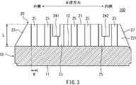
- FIG. FIG. 3 is a cross-sectional view of the brake disc shown in FIG. 1 taken along line III-III.
- FIG. 4 is a IV-IV cross-sectional view of the brake disc shown in FIG.
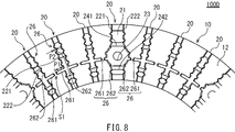
- FIG. 5 is a rear view of the railroad vehicle brake disc according to the second embodiment.
- FIG. 6 is a back view of the railroad vehicle brake disc according to the third embodiment.
- FIG. 7 is a rear view of the railroad vehicle brake disc according to the fourth embodiment.
- FIG. 8 is a back view of the railroad vehicle brake disc according to the fifth embodiment.
- FIG. 9 is a back view of the railroad vehicle brake disc according to the sixth embodiment.
- FIG. 10 is a rear view of the railroad vehicle brake disc according to the seventh embodiment.
- FIG. 11 is a back view of the railroad vehicle brake disc according to the eighth embodiment.
- 12 is a partial perspective view of the brake disc shown in FIG. 11;
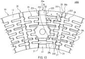
- FIG. 13 is a partially enlarged view of the rear surface of the brake disc shown in FIG. 11.
- FIG. 14 is a graph showing evaluation results of brake disc analysis according to each example and comparative example.
- FIG. 15 is a diagram showing the results of a rotation test using models of brake discs according to Examples and Comparative Examples.
- the brake disc according to the embodiment is a brake disc for railway vehicles.
- a brake disc includes a disc body and a plurality of fins.
- the disc body has an annular plate shape.
- a plurality of fins are arranged on one surface of the disk body such that each of the fins extends from the inner circumference side to the outer circumference side of the disk body.
- Each of the plurality of fins includes two side surfaces arranged in the circumferential direction of the disk body and a top surface connecting the two side surfaces.
- One or more fins of the plurality of fins include a plurality of ridges.
- the plurality of ridges are arranged in the radial direction of the disk body on at least one of the two side surfaces of the fin. Each of the ridges extends between the disk body and the top surface of the fin (first configuration).
- one or more fins are provided with a plurality of ridges on the side surface.
- the brake disc is attached to a rotating member such as a wheel and an air passage is formed by the rotating member, the disc body, and the adjacent fins, the cross-sectional area of the air passage is oriented in the circumferential direction of the disc body. can be reduced to As a result, it is possible to limit the amount of air (ventilation amount) passing through the air passage while the railroad vehicle is running. Therefore, aerodynamic noise can be reduced.
- the plurality of ridges provided on the side surfaces of the fins can also increase the surface area of the brake disc.
- the air that flows into the ventilation passage from the inner circumference of the disc body flows along the side of the fins. can increase the heat transfer coefficient of As a result, it is possible to improve the cooling performance of the brake disc during braking. Therefore, according to the brake disc according to the first configuration, it is possible to efficiently limit the amount of ventilation in the ventilation passage and reduce the aerodynamic noise while ensuring the cooling performance.
- each of the plurality of fins can further include an inner peripheral surface.
- the inner peripheral surface of each fin is connected to the radially inner ends of the disk body of the top surface and two side surfaces.
- the plurality of ridges are preferably arranged outside the inner peripheral surface of each fin in the radial direction of the disk body (second configuration).
- the plurality of ridges are positioned radially outward of the disc body relative to the inner peripheral surface of the fin. Therefore, corners between the inner peripheral surface and both side surfaces are secured in each of the plurality of fins. This corner allows for efficient scooping of air into the air passages formed between adjacent fins while maintaining a high local heat transfer coefficient in this area. Therefore, the cooling performance of the brake disc can be ensured.
- one or more fins among the plurality of fins may be provided with a plurality of ridges on each of the two side surfaces (third configuration).
- a plurality of ridges are provided on both side surfaces of the fin. In this case, the effects of reducing aerodynamic noise and improving cooling performance can be further enhanced.
- each of the plurality of fins may include a plurality of ridges (fourth configuration).
- a plurality of ridges are provided on the side surfaces of all the fins. In this case, the effects of reducing aerodynamic noise and improving cooling performance can be further enhanced.
- the plurality of ridges may include one or more first ridges and one or more second ridges.
- the second protrusion is arranged at a different position from the first protrusion in the radial direction of the disc body.
- the length of the first ridge portion in the circumferential direction of the disc body is greater than the length of the second ridge portion in the circumferential direction (fifth configuration).
- the first protrusion and the second protrusion are provided on the side surface of the fin.
- the length of the first protrusion is greater than the length of the second protrusion in the circumferential direction of the disc body.
- the cross-sectional area of the ventilation path can be particularly reduced at the position of the first ridge, and the amount of ventilation in the ventilation path can be effectively limited. Therefore, aerodynamic noise can be further reduced.
- the surface area of the brake disc can be further increased. Therefore, it is possible to improve the cooling performance of the brake disc during braking. Therefore, it is possible to more efficiently limit the amount of ventilation in the ventilation path while ensuring the cooling performance.
- fins that are adjacent in the circumferential direction of the disk body may each include a first ridge portion and a second ridge portion.
- the first protrusion on one of the adjacent fins faces the first protrusion on the other of the adjacent fins in the circumferential direction (sixth configuration).
- the first protrusion may be arranged on the outer peripheral side of the disc body (seventh configuration).
- the first protrusion may be arranged on the inner peripheral side of the disc body (eighth configuration).
- the first protrusion may be arranged in the radially central portion of the disc body (ninth configuration).
- fins adjacent in the circumferential direction of the disc body among the plurality of fins may each include a plurality of ridges.
- the plurality of ridges can include at least one first ridge.
- the first protrusion on one of the adjacent fins is radially displaced from the first protrusion on the other of the adjacent fins so as to bend the air passage formed between the adjacent fins. (tenth configuration).
- the side surfaces of adjacent fins are provided with a plurality of ridges.
- the brake disc is attached to a rotating member such as a wheel and an air passage is formed by the rotating member, the disc body, and the adjacent fins, the cross-sectional area of the air passage is oriented in the circumferential direction of the disc body. can be reduced to Therefore, it is possible to limit the amount of air (ventilation amount) passing through the air passage while the railroad vehicle is running.
- the plurality of ridges includes a first ridge.
- the ventilation paths formed between the adjacent fins are bent. By bending the ventilation path in this way, the flow resistance to the air passing through the ventilation path can be increased. Therefore, aerodynamic noise can be effectively reduced.
- the plurality of ridges provided on the side surfaces of the fins can also increase the surface area of the brake disc.
- the air that has flowed into the ventilation passage from the inner peripheral side of the disk body tends to flow along the side surface of the fins.
- the air flowing through the ventilation path can be brought into sufficient contact with the rear surface of the disk body and the side surfaces of the fins.
- the bent portion of the air passage changes the direction of the air flow abruptly, it is possible to increase the heat transfer coefficient at the bent portion between the brake disc and the air. As a result, it is possible to improve the cooling performance of the brake disc during braking. Therefore, it is possible to efficiently limit the amount of ventilation in the ventilation path and reduce the aerodynamic noise while ensuring the cooling performance.
- the plurality of ridges may further include a second ridge.
- the second protrusion is arranged at a different position from the first protrusion in the radial direction of the disc body.
- the length of the first ridge portion in the circumferential direction of the disc body is greater than the length of the second ridge portion in the circumferential direction (eleventh configuration).
- the first protrusion on one of the adjacent fins may face the second protrusion on the other of the adjacent fins with a gap in the circumferential direction of the disc body.
- the second protrusion on one of the adjacent fins may face the first protrusion on the other of the adjacent fins with a gap in the circumferential direction of the disc body (twelfth configuration).
- the first ridge portion having a relatively large length in the circumferential direction of the disc body and the second ridge portion having a relatively small length in the circumferential direction of the disc body form a gap. They are facing each other with a gap.
- the cross-sectional area of the air passage can be particularly reduced at the position where the first ridge portion and the second ridge portion face each other, and the amount of ventilation in the air passage can be effectively limited. can. Therefore, aerodynamic noise can be efficiently reduced.
- one or more fins among the plurality of fins may include grooves that traverse the fins (13th configuration).
- one or more fins include grooves traversing them.
- the grooves cause pressure loss in the air flowing through the air passage, thereby reducing the amount of ventilation in the air passage and increasing the heat transfer coefficient between the brake disc and the air.
- the surface area of the fins can be increased. Therefore, according to the thirteenth configuration, the aerodynamic noise can be further reduced, and the cooling performance can be further improved.
- one or more fins among the plurality of fins may include fastening holes for inserting fastening members.
- the groove may be arranged in at least one of a radially outer portion and an inner portion of the disk body relative to the fastening hole (fourteenth configuration).
- the grooves are arranged in each of the radially outer and inner portions of the disk body relative to the fastening holes (fifteenth configuration).
- the grooves are formed in the fins provided with the fastening holes, so that it is possible to allow thermal expansion and contraction of the fins in the radial direction of the disk body. Therefore, when the railway vehicle is braked, the restraint of the fins against thermal expansion is relaxed, and the deformation due to the thermal expansion of the brake disc is reduced. As a result, the stress load on the fastening member inserted into the fastening hole and the brake disk can be reduced, and the durability of the brake disk can be improved.
- a brake disc according to an embodiment of the present disclosure will be described below with reference to the drawings.
- the same or corresponding configurations are denoted by the same reference numerals, and the same description will not be repeated.
- Each figure is a schematic diagram for explaining the main configuration of the brake disc according to the embodiment. Therefore, the detailed shape, dimensional ratio, etc. of the brake disc shown in each drawing may differ from those of the actual brake disc.
- FIG. 1 is a rear view of the railway vehicle brake disc 100 according to the first embodiment.
- FIG. 2 is a partial perspective view of brake disc 100 shown in FIG.
- the brake disc 100 is fastened to a rotating member (not shown) of a railway vehicle.
- the rotating member is an annular disc that is fixed to and rotates with the axle of the railway vehicle.
- a rotating member is, for example, a wheel.
- Brake disc 100 is typically made of steel and can be formed, for example, by forging.
- brake disc 100 includes disc body 10 and a plurality of fins 20 .
- the disc body 10 has a substantially annular plate shape.
- the disc body 10 includes a front side 11 and a back side 12 .
- Surface 11 includes a sliding surface against which brake linings (not shown) are pressed.
- the back surface 12 is the surface facing away from the front surface 11 .
- the rear surface 12 faces the rotating member when the brake disc 100 is fastened to the rotating member.
- the radial direction and the circumferential direction of the disc body 10 may be simply referred to as the radial direction and the circumferential direction.
- the direction of the central axis of the disc main body 10 is referred to as the thickness direction.
- a plurality of fins 20 are provided on the rear surface 12, which is one surface of the disk body 10. More specifically, the plurality of fins 20 are arranged on the rear surface 12 of the disc main body 10 such that each of the fins 20 extends from the inner peripheral side of the disc main body 10 toward the outer peripheral side.
- Each fin 20 includes a top surface 21 and two side surfaces 221,222. In each fin 20, the sides 221, 222 are aligned substantially circumferentially.
- Top surface 21 connects side surfaces 221 and 222 .
- the top surface 21 contacts the rotating member when the brake disc 100 is fastened to the rotating member. Thereby, a space is formed between the rotating member, the disk body 10 and the adjacent fins 20 .
- the space serves as an air passage through which air passes when the brake disc 100 rotates together with the rotating member.
- One or more fins 20 among the plurality of fins 20 include fastening holes 23 .
- two or more fins 20 each include fastening holes 23 .
- Fastening members such as bolts are inserted into the fastening holes 23 when the brake disc 100 is fastened to the rotating member.
- the fastening holes 23 pass through the fins 20 provided with the fastening holes 23 and the disk body 10 in the thickness direction.
- the fastening hole 23 is arranged in the radially central portion of the annular sliding surface 11 (FIG. 2). Therefore, the brake disc 100 is fastened to a rotating member such as a wheel by a fastening member at the radial center position of the sliding surface 11 .
- each of the fins 20 including the fastening holes 23 includes grooves 241 and 242 .
- the fin 20 that does not have the fastening hole 23 also includes the grooves 241 and 242 .
- the grooves 241 and 242 have a concave shape from the top surface 21 of the fin 20 toward the disk main body 10 side. Grooves 241 , 242 extend substantially circumferentially across fin 20 .
- One groove 241 is arranged radially outside the fastening hole 23 in each fin 20 .
- the other groove 242 is arranged radially inside the fastening hole 23 in each fin 20 . Therefore, in the fin 20 having the fastening holes 23 , the fastening holes 23 are positioned between the grooves 241 and 242 .
- the shape of the grooves 241, 242 is not particularly limited.
- the wall surfaces and bottom surfaces of the grooves 241 and 242 can each be composed of flat surfaces, convex curved surfaces, or concave curved surfaces.
- the wall surfaces and bottom surfaces of the grooves 241 and 242 may each be composed of a combination of two or more types of surfaces.
- each of the fins 20 includes a plurality of ridges 25 provided on both side surfaces 221 and 222 thereof.
- the plurality of ridges 25 are arranged substantially radially (in the longitudinal direction of the side surface 221) on one side surface 221 of each fin 20.
- a plurality of ridges 25 are arranged substantially in the radial direction (longitudinal direction of the side surface 222).
- the ridges 25 are provided in a pleat shape on each of the side surfaces 221 and 222 .
- the ridge portion 25 is formed integrally with the side surfaces 221 and 222 .
- FIG. 3 is a III-III cross-sectional view of the brake disc 100 shown in FIG.
- FIG. 4 is a IV-IV cross-sectional view of the brake disc 100 shown in FIG.
- the ridge portion 25 will be described in more detail with reference to FIGS. 3 and 4.
- FIG. 3 is a III-III cross-sectional view of the brake disc 100 shown in FIG.
- FIG. 4 is a IV-IV cross-sectional view of the brake disc 100 shown in FIG.
- the ridge portion 25 will be described in more detail with reference to FIGS. 3 and 4.
- each protrusion 25 substantially extends in the thickness direction of the disk body 10 when viewed from the side 221 side and the side 222 side of the fin 20 .
- at least some of the protrusions 25 may be inclined with respect to the thickness direction.
- each protrusion 25 is in contact with the back surface 12 of the disc body 10 .
- the other end of each protrusion 25 reaches the top surface 21 of the fin 20 .
- the other end of each protrusion 25 does not necessarily have to reach the top surface 21 of the fin 20 . That is, the length L (length in the thickness direction) of each protrusion 25 can be set to be equal to or less than the height (length in the thickness direction) of the fins 20 projecting from the rear surface 12 of the disc body 10 .
- Each protrusion 25 may extend from the back surface 12 of the disk body 10 to the vicinity of the top surface 21 of the fin 20 without reaching the top surface 21 .
- the ridges 25 are arranged at regular intervals over substantially the entire side surface 221 of the fin 20 .
- the ridges 25 are arranged at equal intervals over substantially the entire side surface 222 of the fin 20 .
- the method of arranging the protrusions 25 on the side surfaces 221 and 222 of the fins 20 is not limited to this.
- a plurality of protrusions 25 may be arranged at uneven intervals.
- At least one of the side surfaces 221 and 222 of the fin 20 may be provided with a region in which the ridge portion 25 is arranged and a region in which the ridge portion 25 is not arranged.
- the number of protrusions 25 on each of the side surfaces 221 and 222 may be two or more, and can be determined as appropriate. However, it is preferable that each of the side surfaces 221 and 222 is provided with three or more ridges 25 .
- the area where the protrusion 25 is arranged on one side surface 221 of the fin 20 corresponds to the area where the protrusion 25 is arranged on the other side surface 222 of the fin 20 . That is, in the longitudinal direction (radial direction) of each fin 20, the position where each protrusion 25 is provided on one side surface 221 substantially coincides with the position where each protrusion 25 is provided on the other side surface 222. ing. However, the area where the protrusion 25 is arranged on one side surface 221 of the fin 20 does not necessarily correspond to the area where the protrusion 25 is arranged on the other side surface 222 of the fin 20 .
- one of the side surfaces 221 and 222 is provided with a protrusion 25 in a region on the inner peripheral side of the center of the fastening hole 23 (FIGS. 1 and 2), and the other side surface 221 and 222 is positioned closer to the center of the fastening hole 23 than the center of the fastening hole 23.
- a ridge portion 25 can also be provided in the region on the outer peripheral side.
- Each protrusion 25 protrudes substantially in the circumferential direction from the side surface 221 or the side surface 222 .
- all the protrusions 25 provided on one side surface 221 of the fin 20 have substantially the same protrusion amount.
- all the protrusions 25 provided on the other side surface 222 of the fin 20 have substantially the same protrusion amount.
- the amount of protrusion of the protrusion 25 is the length of the protrusion 25 in the circumferential direction of the disk body 10 .
- the amount of projection of each protrusion 25 on each of the side surfaces 221 and 222 of the fin 20 can be determined as appropriate. However, the amount of protrusion of each protrusion 25 is set to a size that does not interfere with the protrusions 25 of the fins 20 adjacent in the circumferential direction. The amount of protrusion of the protrusion 25 can be determined based on the thickness of the fin 20, for example.
- the thickness of each fin 20 is the length of the fin 20 in a direction substantially perpendicular to the longitudinal direction (the radial direction of the disk body 10) and the height direction (the thickness direction of the disk body 10) of the fin 20. be. For example, when the thickness of the fin 20 having the smallest thickness among the plurality of fins 20 provided on the disc main body 10 is T, the projection amount of each protrusion 25 is 1/3 ⁇ T or more. can do.
- all the protrusions 25 on each of the side surfaces 221 and 222 of the fin 20 have the same protrusion amount.
- the amount of projection of the protrusion 25 is relatively small, and the radially inner and outer regions of the region are , the protrusion amount of the ridge portion 25 can be made relatively large.
- the protrusion amount of the protrusion 25 is relatively large, and in the radially inner and outer regions of the region The protrusion amount of the protrusion 25 may be relatively small.
- the other side surface 222 of the fin 20 can be divided into a plurality of regions in the radial direction, and the protrusion amount of the ridge portion 25 can be changed for each region.
- the protrusion amount of the protrusion 25 is relatively small, and in the radially inner and outer regions of the region, the protrusion 25 protrudes.
- the amount can be relatively large.
- the protrusion amount of the protrusion 25 is relatively large, and in the radially inner and outer regions of the region The protrusion amount of the protrusion 25 may be relatively small.
- each protrusion 25 (the length in the longitudinal direction of the side surface 221 or side surface 222 of the fin 20) may also be determined as appropriate. On one side surface 221 of the two side surfaces 221 and 222 of the fin 20, all the protrusions 25 may have the same width, or the protrusions 25 having different widths may be mixed. good too. Similarly, on the other side surface 222, all the ridges 25 may have the same width, or ridges 25 having different widths may be mixed.
- Each ridge portion 25 can have various cross-sectional shapes.
- Each ridge 25 can have, for example, a semi-circular shape, a semi-elliptical shape, a semi-oval track shape, or a polygonal cross section such as a triangle or a square.
- all the ridges 25 may have the same cross-sectional shape, or the ridges 25 having different cross-sectional shapes may be May be mixed.
- all the ridges 25 may have the same cross-sectional shape, or ridges 25 having different cross-sectional shapes may be mixed.
- the cross section of the ridge portion 25 means a cross section when the ridge portion 25 is cut along a plane substantially perpendicular to its extending direction.
- the sliding surface (the surface 11 of the disc body 10) against which the brake lining is pressed is provided only on one side in the thickness direction.
- the plurality of ridges 25 are arranged between the inner peripheral end and the outer peripheral end (within the range of the sliding width) of the annular sliding surface 11 .
- the plurality of ridges 25 are preferably arranged radially within the top surface 21 of the fin 20 .
- the plurality of ridges 25 are arranged radially outside the inner peripheral surface 27 of the fin 20 .
- the plurality of ridges 25 are arranged radially inside the outer peripheral surface 28 of the fin 20 .
- the inner peripheral surface 27 is connected to the inner end of the radial ends of the top surface 21 and side surfaces 221 and 222 .
- the outer peripheral surface 28 is connected to the outer edge of the radial ends of the top surface 21 and side surfaces 221 and 222 .
- the outer peripheral surface 28 is inclined with respect to the thickness direction of the disc body 10 so that the height of the fins 20 decreases toward the radially outer side.
- the inner peripheral surface 27 may be inclined with respect to the thickness direction of the disc body 10 so that the height of the fins 20 increases radially outward. In the area of the top surface 21 between the inner peripheral surface 27 and the outer peripheral surface 28, the height of the fins 20 is substantially constant.
- each of the plurality of fins 20 arranged on the rear surface 12 of the disc body 10 is provided with the plurality of protrusions 25 .
- a plurality of ridges 25 are provided on side surfaces 221 and 222 of each fin 20 .
- the ridges 25 provided on the side surfaces 221 and 222 of each fin 20 can also increase the surface area of the brake disc 100 . Further, when the railroad vehicle is running, the air that has flowed into the air passage from the inner peripheral side of the disk body 10 flows along the side surfaces 221 and 222 of the fins 20, so that the protrusions provided on the side surfaces 221 and 222 of the fins 20 are not formed.
- the ridges 25 can increase the heat transfer coefficient between the brake disc 100 and air. As a result, it is possible to improve the cooling performance of the brake disc 100 during braking. Therefore, according to the brake disc 100 according to the present embodiment, the aerodynamic noise can be reduced by efficiently limiting the amount of ventilation in the ventilation path while ensuring the cooling performance.
- each of the fins 20 with fastening holes 23 includes grooves 241, 242 across it. Further, fins 20 that do not have fastening holes 23 also include grooves 241 and 242, respectively. These grooves 241 and 242 cause pressure loss in the air flowing through the air passage, thereby reducing the amount of ventilation in the air passage and increasing the heat transfer coefficient between the brake disc 100 and the air. Also, the grooves 241 and 242 can increase the surface area of each fin 20 . Therefore, by providing the grooves 241 and 242 in each fin 20, the aerodynamic noise can be further reduced, and the cooling performance can be further improved.
- the grooves 241 and 242 are formed in the fin 20 including the fastening hole 23, it is possible to allow thermal expansion and contraction of the fin 20 in the radial direction. Therefore, during braking of the railway vehicle, the restraint of the fins 20 against thermal expansion is relaxed, and the deformation due to the thermal expansion of the brake disc 100 is reduced. As a result, the stress load on the fastening member inserted into the fastening hole 23 and the brake disc 100 can be reduced, and the durability of the brake disc 100 can be improved.
- the plurality of ridges 25 are arranged radially outward of the inner peripheral surface 27 of the fin 20 .
- corners formed between the inner peripheral surface 27 and the side surfaces 221 and 222 of each fin 20 can be secured. This corner allows air to be efficiently scooped into the air passages formed between adjacent fins 20 while maintaining a high local heat transfer coefficient in this region. Therefore, the cooling performance of the brake disc 100 can be favorably maintained.
- the outer peripheral surface 28 of each fin 20 is inclined with respect to the thickness direction of the disc body 10 so that the height of the fin 20 decreases radially outward.
- the plurality of ridges 25 are arranged radially inward of the outer peripheral surface 28 .
- FIG. 5 is a rear view of the railroad vehicle brake disc 100A according to the second embodiment.
- FIG. 5 shows a portion of the brake disc 100A.
- a brake disc 100 ⁇ /b>A according to this embodiment differs from the brake disc 100 according to the first embodiment in the configuration of the ridge portion 26 .
- each of the fins 20 includes a plurality of ridges 26 .
- a plurality of ridges 26 are provided on both side surfaces 221 and 222 of each fin 20 .
- the plurality of ridges 26 includes one or more first ridges 261 and one or more second ridges 262 .
- a plurality of first ridges 261 and a plurality of second ridges 262 are provided on each of the side surfaces 221 and 222 .
- the total number of the protrusions 261 and 262 is three or more.
- the first protrusions 261 are arranged on the inner peripheral side and the outer peripheral side of the disc main body 10, respectively. That is, the first ridges 261 are provided inside and outside the fastening hole 23 in the radial direction of the disk body 10 .
- the second ridge portion 262 is arranged at a different position from the first ridge portion 261 in the radial direction.
- a plurality of second ridges 262 are provided between the first ridges 261 on the inner circumference side of the disc body 10 and the first ridges 261 on the outer circumference side of the disc body 10 . are placed. These second ridges 262 are arranged in the radial direction.
- the ridges 261 and 262 extend between the disk body 10 and the top surfaces 21 of the fins 20, respectively, like the ridges 25 in the first embodiment.
- the ridges 261 and 262 protrude substantially in the circumferential direction of the disk body 10 from the side surfaces 221 or 222 of the fins 20 .
- the protrusion amount P1 of the first protrusion 261 is larger than the protrusion amount P2 of the second protrusion 262 .
- the protrusion amounts P1 and P2 are the lengths of the protrusions 261 and 262 in the circumferential direction, respectively.
- the protrusion amount P1 of the first protrusion 261 can be, for example, 2.0 times or more the protrusion amount P2 of the second protrusion 262.
- the protrusion amount P2 of the second ridge portion 262 is 1/3 ⁇ T, where T is the thickness of the fin 20 having the smallest thickness among the plurality of fins 20, similarly to the ridge portion 25 in the first embodiment. It can be as above.
- the positions of the first protrusions 261 in the radial direction of the disk body 10 are substantially the same for all fins 20 . Therefore, the first protrusion 261 of one fin 20 of the adjacent fins 20 faces the first protrusion 261 of the other fin 20 in the circumferential direction.
- the first protrusions 261 of adjacent fins 20 do not interfere with each other. That is, a gap S1 exists between the first ridges 261 facing each other in the circumferential direction.
- the size of the gap S1 in the circumferential direction can be 0.7 ⁇ T or more and 5.0 ⁇ T or less, where T is the thickness of the fin 20 having the smallest thickness among the plurality of fins 20 .
- each fin 20 are provided with a first protrusion 261 and a second protrusion 262, and the protrusion amount P1 of the first protrusion 261 is equal to the protrusion of the second protrusion 262. greater than the quantity P2.
- the cross-sectional area of the ventilation path can be particularly reduced at the position of the first protrusion 261, and the amount of ventilation in the ventilation path can be effectively limited. Therefore, aerodynamic noise can be further reduced.
- the side surfaces 221 and 222 of each fin 20 are provided with the first protrusions 261 having a relatively large protrusion amount P1.
- the surface area of the brake disc 100A can be further enlarged. Therefore, it is possible to improve the cooling performance of the brake disc 100A during braking.
- the brake disc 100A according to the present embodiment can also efficiently limit the amount of ventilation in the air passage to reduce aerodynamic noise while ensuring cooling performance.
- FIG. 6 is a rear view of the railroad vehicle brake disc 100B according to the third embodiment.
- FIG. 6 shows a portion of the brake disc 100B.
- each fin 20 includes the same protrusions 26 as in the second embodiment on both side surfaces 221 and 222 thereof. That is, the side surfaces 221 and 222 of each fin 20 are provided with a first protrusion 261 having a relatively large protrusion amount P1 and a second protrusion 262 having a relatively small protrusion amount P2.
- the first protrusion 261 is arranged only on the outer peripheral side of the disc body 10 . That is, the first protrusion 261 is provided only outside the fastening hole 23 in the radial direction of the disk body 10 .
- the first ridge portion 261 is the most in the radial direction. positioned outside.
- FIG. 7 is a rear view of a railroad vehicle brake disc 100C according to the fourth embodiment.
- FIG. 7 shows a portion of the brake disc 100C.
- each fin 20 includes the same protrusions 26 as in the second embodiment on both side surfaces 221 and 222 thereof. That is, the side surfaces 221 and 222 of each fin 20 are provided with a first protrusion 261 having a relatively large protrusion amount P1 and a second protrusion 262 having a relatively small protrusion amount P2.
- the first protrusion 261 is arranged only on the inner peripheral side of the disc main body 10 . That is, the first protrusion 261 is provided only inside the fastening hole 23 in the radial direction of the disc body 10 .
- the first ridges 261 are the most in the radial direction. positioned inside.
- the first protrusion 261 is arranged on the inner peripheral side of the disc main body 10 .
- the first protrusions 261 are arranged on the outer peripheral side of the disc main body 10.
- dust and the like are clogged between the first protrusions 261 facing in the circumferential direction of the disc main body 10. Maintenance becomes easier when In addition, arranging the first ridge portion 261 on the inner peripheral side of the disc main body 10 is also advantageous in terms of formability by forging the brake disc 100C.
- FIG. 8 is a back view of the railroad vehicle brake disc 100D according to the fifth embodiment.
- FIG. 8 shows a portion of the brake disc 100D.
- each fin 20 includes the same protrusions 26 as in the second embodiment on both side surfaces 221 and 222 thereof. That is, the side surfaces 221 and 222 of each fin 20 are provided with a first protrusion 261 having a relatively large protrusion amount P1 and a second protrusion 262 having a relatively small protrusion amount P2.
- the first ridge portion 261 is arranged in the central portion of the disk body 10 in the radial direction.
- the first protrusion 261 is arranged at substantially or substantially the same position as the fastening hole 23 in the radial direction of the disc body 10 .
- the second ridge portion 262 is arranged radially inside and outside the first ridge portion 261 .
- a plurality of second protrusions 262 are provided radially inward of the first protrusions 261 on each of the side surfaces 221 and 222 of the fin 20 .
- a plurality of second ridges 262 are provided radially outside the first ridges 261 .
- FIG. 9 is a rear view of a railway vehicle brake disc 100E according to the sixth embodiment.
- FIG. 9 shows a portion of the brake disc 100E.
- each fin 20 includes the same protrusions 26 as in the second embodiment on both side surfaces 221, 222 thereof. That is, the side surfaces 221 and 222 of each fin 20 are provided with a first protrusion 261 having a relatively large protrusion amount P1 and a second protrusion 262 having a relatively small protrusion amount P2.
- the first protrusion 261 is arranged on the inner peripheral side of the disc body 10 . Further, in this embodiment, as in the fifth embodiment, the first ridge portion 261 is arranged at the central portion in the radial direction of the disc body 10 . In the example shown in FIG. 9 , one second protrusion 262 is arranged between two first protrusions 261 on each of the side surfaces 221 and 222 of the fin 20 . On each side surface 221 , 222 of the fin 20 , a second ridge portion 262 is also provided radially outward with respect to the first ridge portion 261 .
- the first ridges 261 are arranged on the inner peripheral side of the disc body 10 and at the center in the radial direction.
- the first ridges 261 can also be arranged on the outer peripheral side of the disk body 10 and at the center in the radial direction.
- FIG. 10 is a back view of the railroad vehicle brake disc 100F according to the seventh embodiment.
- FIG. 10 shows a portion of the brake disc 100F.
- both side surfaces 221 and 222 of each fin 20 are provided with a plurality of first protrusions 261 described above.
- the side surfaces 221 and 222 of each fin 20 are not provided with the second ridges 262 .
- FIG. 11 is a rear view of the railroad vehicle brake disc 100G according to the eighth embodiment.
- 12 is a partial perspective view of the brake disc 100G shown in FIG. 11.
- FIG. 11 and 12 a brake disc 100G according to this embodiment has substantially the same configuration as the brake disc 100 (FIGS. 1 and 2) according to the first embodiment.
- the brake disc 100 ⁇ /b>G according to this embodiment differs from the brake disc 100 according to the first embodiment in the configuration of the ridge portion 29 .
- Each of the fins 20 includes a plurality of ridges 29 as in the above embodiments. More specifically, a plurality of ridges 29 are provided on one side surface 221 of each fin 20 . The plurality of ridges 29 are arranged substantially radially (in the longitudinal direction of the side surface 221) on the side surface 221 of each fin 20. As shown in FIG. A plurality of ridges 29 are also provided on the other side surface 222 of each fin 20 . The plurality of ridges 29 are arranged substantially radially (in the longitudinal direction of the side surface 222) on the side surface 222 of each fin 20. As shown in FIG. The ridges 29 are provided in a pleated shape on each of the side surfaces 221 and 222 . The ridge portion 29 is formed integrally with the side surfaces 221 and 222 .
- the plurality of ridges 29 includes a plurality of ridges 29L and a plurality of ridges 29S.
- Each of the ridges 29L and 29S protrudes from the side surface 221 or side surface 222 of the fin 20 substantially in the circumferential direction.
- the protrusion amount of the protrusion 29L is larger than the protrusion amount of the protrusion 29S.
- Each fin 20 includes a mixture of ridges 29L having a relatively large amount of protrusion and ridges 29S having a relatively small amount of protrusion.
- the amount of protrusion of the protrusions 29L and 29S is the length of the protrusions 29L and 29S in the circumferential direction of the disk body 10. As shown in FIG.
- ridges 29L with a relatively large amount of protrusion and ridges 29S with a relatively small amount of protrusion are alternately arranged.
- the ridges 29L and 29S are, for example, arranged at regular intervals over the entire side surfaces 221 and 222 of the fin 20 .
- the protrusions 29L and 29S may be arranged at uneven intervals.
- Each of the ridges 29L, 29S extends between the disk body 10 and the top surface 21 of the fin 20.
- Each of the ridges 29L and 29S extends substantially in the thickness direction of the disc body 10, for example. However, the protrusions 29L and 29S may be inclined with respect to the thickness direction when the fin 20 is viewed from the side.
- each fin 20 one end of the ridges 29L and 29S is in contact with the back surface 12 of the disk body 10.
- the other ends of the protrusions 29 ⁇ /b>L and 29 ⁇ /b>S may reach the top surface 21 of the fin 20 or may not reach the top surface 21 of the fin 20 . That is, the length of the ridges 29L and 29S in the thickness direction of the disk body 10 can be less than or equal to the distance from the back surface 12 of the disk body 10 to the top surface 21 of the fin 20.
- FIG. 13 is a partially enlarged view of the rear surface of the brake disc 100G.
- the protrusions 29L and 29S will be described in more detail with reference to FIG.
- the positions in the radial direction of the ridges 29L having a relatively large amount of protrusion are the fins 20a and 20b. and different.
- the ridge portion 29L of the fin 20a is radially displaced from the ridge portion 29L of the fin 20b so as to bend the air passage formed between the fins 20a and 20b. That is, the rib portion 29L projecting from the side surface 222 of one fin 20a does not face the rib portion 29L projecting from the side surface 221 of the other fin 20b in the circumferential direction.
- the air passage has one or more bends in the air flow.
- the air passage has a shape such that the direction from the air inlet side to the air outlet side cannot be visually recognized.
- a gap S1 is formed between the protrusion 29L of the fin 20a and the fin 20b. More specifically, the rib portion 29L of the fin 20a faces the rib portion 29S of the fin 20b with a gap S1 in the circumferential direction. Similarly, a gap S2 is formed between the fin 20a and the protrusion 29L of the fin 20b. More specifically, the rib portion 29S of the fin 20a faces the rib portion 29L of the fin 20b with a gap S2 in the circumferential direction. The position of the gap S1 between the ridge 29L of the fin 20a and the fin 20b is displaced in the circumferential direction from the position of the gap S2 between the ridge 29L of the fin 20b and the fin 20a.
- the sizes of the gaps S1 and S2 in the circumferential direction can be determined based on the thickness of the fins 20, for example.
- the thickness of the fins 20 is the length of the fins 20 in a direction substantially perpendicular to the radial direction and thickness direction of the disk body 10 .
- the gaps S1 and S2 in the circumferential direction are 0.7 ⁇ T or more and 5 .0 ⁇ T or less.
- the size of the gap S1 is, for example, substantially equal to the size of the gap S2. However, the size of the gap S1 may differ from the size of the gap S2.
- the protrusions 29L and 29S have projection amounts A L and A S , respectively.
- the protrusion amounts A L and A S can also be determined based on the thickness of the fin 20, for example.
- the amount of protrusion AL of the ridge portion 29L can be, for example, 1.0 ⁇ T or more, where T is the thickness of the fin 20 having the smallest thickness among the plurality of fins 20 .
- the protrusion amount AL of the protrusion 29L is set to a size that does not interfere with the protrusion 29S facing in the circumferential direction.
- the protrusion amount AS of the protrusion 29S is, for example, 0.85 times or less the protrusion amount AL of the protrusion 29L.
- the projecting ends of the ridges 29L and 29S have, for example, a semicircular cross section.
- the projecting ends of the ridges 29L and 29S may have, for example, a semi-elliptical shape, a polygonal cross section such as a triangle or a square.
- the protruding ends of the plurality of ridges 29L, 29S may all have the same cross-sectional shape, or may have protruding ends with different cross-sectional shapes.
- the streaks 29L and 29S may be mixed.
- the cross section here means a cross section obtained by cutting the ridges 29L and 29S along a plane substantially perpendicular to the thickness direction of the disk body 10. As shown in FIG.
- each of the ridges 29L, 29S (the length in the longitudinal direction of the side surfaces 221, 222 of the fin 20) can be determined as appropriate. On each of the side surfaces 221, 222 of the fin 20, all of the plurality of ridges 29L, 29S may have the same width, or the ridges 29L, 29S having different widths may be mixed. good.
- each of the plurality of fins 20 arranged on the back surface 12 of the disc body 10 is provided with the plurality of protrusions 29 .
- a plurality of ridges 29 are provided on side surfaces 221 and 222 of each fin 20 .
- the plurality of ridges 29 includes ridges 29L and 29S.
- the positions of the ridges 29L having a relatively large amount of protrusion AL are offset in the radial direction of the disk body 10 between the adjacent fins 20 .
- the air passages formed between the adjacent fins 20 are bent, so that the flow resistance to the air passing through the air passages can be increased. Therefore, aerodynamic noise can be reduced.
- the ridges 29L, 29S provided on the side surfaces 221, 222 of the fins 20 can also increase the surface area of the brake disc 100G.
- the air that has flowed into the air passage from the inner peripheral side of the disk body 10 tends to flow along the side surfaces 221 and 222 of the fins 20.
- the air flowing through the ventilation path can sufficiently contact the rear surface 12 of the disk body 10 and the side surfaces 221 and 222 of the fins 20 .
- the bent portion of the air passage changes the direction of the flow of air abruptly, the heat transfer coefficient at the bent portion between the brake disc 100G and the air can be increased.
- the cooling performance of the brake disc 100G during braking can be improved. Therefore, according to the brake disc 100G according to the present embodiment, it is possible to efficiently limit the amount of ventilation in the ventilation path and reduce the aerodynamic noise while ensuring the cooling performance.
- a ridge portion 29L having a relatively large amount of protrusion AL and a ridge portion 29S having a relatively small amount of protrusion AS are opposed to each other with gaps S1 and S2 therebetween.
- the cross-sectional area of the ventilation path can be particularly reduced at the position where the protrusion 29L and the protrusion 29S face each other, and the flow resistance to the air passing through the ventilation path can be further increased. . Therefore, it is possible to effectively limit the amount of ventilation in the ventilation path and reduce aerodynamic noise.
- the protrusions 29L and 29S are arranged between the inner peripheral end and the outer peripheral end of the annular sliding surface 11 (within the range of the sliding width). be done.
- the ridges 29L and 29S are preferably arranged within the range of the top surfaces 21 of the fins 20 in the radial direction.
- the ridges 29L and 29S are arranged radially outward of the inner peripheral surface 27 of the fin 20, for example. Therefore, as in the above-described embodiments, it is possible to efficiently scoop air into the air passages formed between the adjacent fins 20 and maintain a high local heat transfer coefficient in this area.
- the cooling performance of the brake disc 100G can be favorably maintained.
- the ridges 29L and 29S are arranged radially outward of the outer peripheral surface 28 of the fin 20 . Therefore, as in the above-described embodiments, during braking of the brake disc 100G, the outer peripheral side of the fin 20 and the protrusions 29L and 29S can be made less likely to interfere with rotating members such as wheels.
- all the fins 20 arranged on the back surface 12 of the disc body 10 each have a plurality of ridges 25 or a plurality of ridges. 26 included.
- the plurality of fins 20 arranged on the back surface 12 of the disk body 10 only some of the fins 20 may be formed with the plurality of ridges 25 or 26.
- FIG. That is, one or more fins 20 among the plurality of fins 20 may include the ridge portion 25 or the ridge portion 26 .
- two or more fins 20 out of the plurality of fins 20 include the ridge portion 25 or the ridge portion 26. More preferably, all fins 20 include ridges 25 or ridges 26 .
- the ridges 25 or 26 are provided on both side surfaces 221, 222 of each fin 20.
- each fin 20 only one of the two side surfaces 221, 222 may be formed with a plurality of ridges 25 or a plurality of ridges 26.
- FIG. in the brake discs 100, 100A to 100F the fins 20 including the ridges 25 or 26 provided on both side surfaces 221 and 222, and the ridges 25 or ridges provided only on one of the side surfaces 221 and 222 Two or more of the fins 20 including the portion 26 and the fins 20 not including the ridges 25 and 26 may be mixed.
- each fin 20 may not have the protrusion 29S.
- each of the adjacent fins 20 may be provided with only the protrusion 29L.
- one of the adjacent fins 20 may be provided with the protrusions 29L and 29S, and the other of the adjacent fins 20 may be provided with only the protrusion 29L.
- the ventilation paths between the adjacent fins 20 are formed. can be bent.
- the side surface 221 or the side surface 222 is provided with two or more ridges 29L, more preferably three or more ridges 29L. is provided.
- all the fins 20 arranged on the back surface 12 of the disk body 10 each include a plurality of ridges 29 .
- the plurality of fins 20 arranged on the back surface 12 of the disk body 10 only some of the fins 20 may be formed with the plurality of ridges 29.
- it is preferable that three or more fins 20 out of the plurality of fins 20 include the ridges 29, and all the fins 20 have protrusions. It is more preferable to include the ridges 29 .
- the protrusion 29L having a relatively large protrusion amount A L is arranged substantially over the entire surface.
- the ridges 29L are provided only in the region on the inner peripheral side of the center of the fastening hole 23, and the ventilation path is formed by the ridges 29L only on the inner peripheral side of the center of the fastening hole 23. It can be bent.
- the protrusion 29L is provided only in the region on the outer peripheral side of the center of the fastening hole 23, and the ventilation path is formed by the protrusion 29L only on the outer peripheral side of the center of the fastening hole 23. It can be bent.
- the protrusion 29L may be provided only in the region near the fastening hole 23, and the air passage may be bent by the protrusion 29L only at the center in the radial direction.
- a ridge portion 29S having a relatively small amount of protrusion AS may or may not be provided in the region where the ridge portion 29L exists and the region where the ridge portion 29L does not exist. It doesn't have to be. If each fin 20 has both the ridges 29L and 29S, the total number of the ridges 29L and 29S is preferably three or more.
- each fin 20 includes grooves 241, 242.
- each fin 20 can also include only one of the grooves 241,242.
- each fin 20 may not include any of the grooves 241,242.
- fins 20 including at least one of grooves 241, 242 and fins 20 not including grooves 241, 242 may be mixed.
- the fin 20 including the fastening hole 23 is provided with at least one of the grooves 241 and 242, and the other fins 20 are provided with the grooves 241 and 242. It does not have to be provided.
- the grooves 241 and 242 may not be provided in the fin 20 including the fastening hole 23 and at least one of the grooves 241 and 242 may be provided in the other fins 20 .
- the grooves 241 and 242 may not be provided in all the fins 20 arranged on the back surface 12 of the disk body 10. FIG. When at least one of the grooves 241 and 242 is provided in the fin 20 that does not include the fastening hole 23, the groove 241 and/or the groove 242 can be freely positioned in the radial direction without being restricted by the fastening hole 23. can be placed.
- Example 1 In order to verify the effects of the present disclosure, as Example 1, general-purpose thermo-fluid analysis software (product name: ANSYS Fluent (manufactured by ANSYS) was used to perform a three-dimensional thermal fluid analysis assuming that a railway vehicle is running at a steady speed of 330 km/h. Further, as Examples 2 to 7, the same analysis as described above was performed on the brake discs 100A to 100F (FIGS. 5 to 10) according to the second to seventh embodiments, respectively. As a comparative example, the same analysis as described above was performed on a brake disc obtained by removing the ridges on the side surfaces of the fins from the brake disc according to the first embodiment. Each brake disc according to each example and comparative example has 33 fins.
- the level of aerodynamic noise and cooling performance were evaluated for the brake discs according to each example and comparative example.
- the ventilation rate [kg/s] obtained by gas isothermal flow analysis was used as an evaluation index indicating the level of aerodynamic noise.
- This ventilation amount is the amount of ventilation between the brake disc and the rotating member (wheel) per brake disc.
- the heat dissipation index [W/K] obtained by non-isothermal gas flow analysis was used as an evaluation index that indicates the cooling performance of the brake disc.
- This heat dissipation index is the integrated value of the average heat transfer coefficient of the disc surface and the disc surface area per brake disc. A higher heat dissipation index means a higher cooling performance of the brake disc.
- the heat radiation efficiency was used as an evaluation index to show the efficiency of aerodynamic noise reduction.
- the heat radiation efficiency is a value obtained by dividing the heat radiation index by the ventilation amount.
- a higher heat radiation efficiency means that the amount of airflow can be restricted without impairing the cooling performance of the brake disc, that is, the aerodynamic noise is efficiently reduced.
- Table 1 and FIG. 14 show the evaluation results of the brake discs according to each example and comparative example.
- Example 1 As shown in Table 1 and FIG. 14, the comparative example has a high heat radiation index and excellent cooling performance.
- the heat radiation index is comparable to that of the comparative example, and it can be seen that excellent cooling performance can be obtained.
- Example 1 the ventilation rate decreased as compared with the comparative example. That is, in Example 1, it was possible to reduce the level of aerodynamic noise while maintaining excellent cooling performance equivalent to that of the comparative example. In terms of heat dissipation efficiency, Example 1 is significantly higher than Comparative Example. Therefore, it can be said that in Example 1, the aerodynamic noise was efficiently reduced while ensuring the cooling performance of the brake disc as compared with the comparative example.
- Example 2 to 7 in which ridges with a relatively large amount of protrusion were provided on both sides of each fin, the amount of ventilation decreased and the level of aerodynamic noise decreased compared to the comparative example.
- Example 3 was higher than the comparative example, and Example 2 and Examples 4 to 7 were slightly lower than the comparative example.
- the heat dissipation efficiency was greatly improved compared to the comparative example. Therefore, it can be said that in Examples 2 to 7 as well, the aerodynamic noise was efficiently reduced while ensuring the cooling performance of the brake disc.
- Example 8 a brake disc having a shape similar to that of the brake disc 100G (FIGS. 11 to 13) according to the eighth embodiment was measured in three dimensions similar to that of the first example. A thermo-fluid analysis was performed. Table 2 shows the evaluation results of the brake discs according to Example 8 and Comparative Example. The comparative example is the same as the comparative example in the first embodiment.
- Example 8 As shown in Table 2, in Example 8, the ventilation rate was significantly reduced compared to the comparative example. On the other hand, in Example 8, the heat release index was slightly lower than in the comparative example. However, in Example 8, the heat dissipation efficiency is remarkably higher than in the comparative example. Therefore, in Example 8, it can be said that the decrease in the cooling performance of the brake disc is suppressed although the aerodynamic noise is significantly reduced.
- Models (disk test specimens) of the brake discs according to Examples 1 to 8 were prepared, and a rotation test was conducted using each model.
- the disk specimens of Examples 1 to 8 were each attached to a wheel model (wheel specimen) and rotated at a predetermined rotational speed, and a sound level meter was placed 70 cm away from the surface of each disk specimen. The sound pressure level was measured by
- a similar rotation test was also performed on a wheel test body to which no disk test body was attached and a brake disk model (disk test body) according to the comparative example. The results of the rotation test are shown in FIG. In FIG.
- Example 8 in which each fin was provided with a ridge, the sound pressure level was reduced compared to the wheel test body and the comparative example in which each fin did not have a ridge. rice field.
- Example 8 in which the air passages between the adjacent fins were bent, the sound pressure level was particularly low.
- the tendency of the sound pressure level obtained in this rotation test agrees with the tendency of the ventilation rate obtained in the analysis of the first and second examples.
- the magnitude relationship of the air flow rate in the analysis corresponds to the magnitude relationship of the sound pressure level, and it can be said that the evaluation of the aerodynamic noise reduction effect in the analysis is accurate.
- brake disc 10 disc body 20
- 20a, 20b fin 21: top surface 221
- 222 side surface 27: inner peripheral surface 23: fastening hole 241, 242: groove 25, 26, 261, 262, 29, 29L, 29S: ridges S1, S2: gaps
Landscapes
- Engineering & Computer Science (AREA)
- General Engineering & Computer Science (AREA)
- Mechanical Engineering (AREA)
- Braking Arrangements (AREA)
Priority Applications (7)
| Application Number | Priority Date | Filing Date | Title |
|---|---|---|---|
| JP2023511457A JPWO2022210831A1 (https=) | 2021-04-01 | 2022-03-30 | |
| BR112023019782A BR112023019782A2 (pt) | 2021-04-01 | 2022-03-30 | Disco de freio |
| EP22781042.1A EP4316943A4 (en) | 2021-04-01 | 2022-03-30 | BRAKE DISC |
| KR1020237036999A KR20230162067A (ko) | 2021-04-01 | 2022-03-30 | 브레이크 디스크 |
| US18/550,158 US20240159282A1 (en) | 2021-04-01 | 2022-03-30 | Brake disc |
| CN202280026227.6A CN117157472A (zh) | 2021-04-01 | 2022-03-30 | 制动盘 |
| JP2025106297A JP2025123529A (ja) | 2021-04-01 | 2025-06-24 | ブレーキディスク |
Applications Claiming Priority (6)
| Application Number | Priority Date | Filing Date | Title |
|---|---|---|---|
| JP2021-062857 | 2021-04-01 | ||
| JP2021062857 | 2021-04-01 | ||
| JP2021158347 | 2021-09-28 | ||
| JP2021-158348 | 2021-09-28 | ||
| JP2021158348 | 2021-09-28 | ||
| JP2021-158347 | 2021-09-28 |
Publications (1)
| Publication Number | Publication Date |
|---|---|
| WO2022210831A1 true WO2022210831A1 (ja) | 2022-10-06 |
Family
ID=83456474
Family Applications (1)
| Application Number | Title | Priority Date | Filing Date |
|---|---|---|---|
| PCT/JP2022/015815 Ceased WO2022210831A1 (ja) | 2021-04-01 | 2022-03-30 | ブレーキディスク |
Country Status (6)
| Country | Link |
|---|---|
| US (1) | US20240159282A1 (https=) |
| EP (1) | EP4316943A4 (https=) |
| JP (2) | JPWO2022210831A1 (https=) |
| KR (1) | KR20230162067A (https=) |
| BR (1) | BR112023019782A2 (https=) |
| WO (1) | WO2022210831A1 (https=) |
Cited By (2)
| Publication number | Priority date | Publication date | Assignee | Title |
|---|---|---|---|---|
| CN116336111A (zh) * | 2023-03-14 | 2023-06-27 | 中车唐山机车车辆有限公司 | 一种车用制动盘及其制备方法 |
| WO2025002654A1 (de) * | 2023-06-26 | 2025-01-02 | Knorr-Bremse Systeme für Schienenfahrzeuge GmbH | Reibring für eine radbremsscheibe und radbremsscheibe für ein schienenfahrzeug |
Citations (6)
| Publication number | Priority date | Publication date | Assignee | Title |
|---|---|---|---|---|
| JPS56164237A (en) * | 1980-05-21 | 1981-12-17 | Nissan Motor Co Ltd | Disc brake rotor |
| JPH0238540U (https=) * | 1988-09-05 | 1990-03-14 | ||
| JP2011520080A (ja) * | 2008-05-05 | 2011-07-14 | フレニ ブレンボ エス.ピー.エー. | ベンチレーテッド型ディスクブレーキ用ディスクのブレーキバンド |
| WO2014038621A1 (ja) | 2012-09-07 | 2014-03-13 | 新日鐵住金株式会社 | 鉄道車両用ブレーキディスク |
| WO2016156838A1 (en) * | 2015-03-31 | 2016-10-06 | Alcon Components Limited | Brake disc |
| JP2017110755A (ja) * | 2015-12-17 | 2017-06-22 | 株式会社エンドレスプロジェクト | 自動車用ディスクブレーキのディスクローター |
Family Cites Families (2)
| Publication number | Priority date | Publication date | Assignee | Title |
|---|---|---|---|---|
| WO2020229483A2 (de) * | 2019-05-15 | 2020-11-19 | Knorr-Bremse Systeme für Schienenfahrzeuge GmbH | Radbremsscheibe für schienenfahrzeuge |
| CN112443602A (zh) * | 2019-08-29 | 2021-03-05 | 江苏鼎泰工程材料有限公司 | 城市快轨列车、高速动车组列车用分体式轮装制动盘 |
-
2022
- 2022-03-30 EP EP22781042.1A patent/EP4316943A4/en active Pending
- 2022-03-30 US US18/550,158 patent/US20240159282A1/en active Pending
- 2022-03-30 WO PCT/JP2022/015815 patent/WO2022210831A1/ja not_active Ceased
- 2022-03-30 BR BR112023019782A patent/BR112023019782A2/pt active Search and Examination
- 2022-03-30 KR KR1020237036999A patent/KR20230162067A/ko not_active Ceased
- 2022-03-30 JP JP2023511457A patent/JPWO2022210831A1/ja active Pending
-
2025
- 2025-06-24 JP JP2025106297A patent/JP2025123529A/ja active Pending
Patent Citations (6)
| Publication number | Priority date | Publication date | Assignee | Title |
|---|---|---|---|---|
| JPS56164237A (en) * | 1980-05-21 | 1981-12-17 | Nissan Motor Co Ltd | Disc brake rotor |
| JPH0238540U (https=) * | 1988-09-05 | 1990-03-14 | ||
| JP2011520080A (ja) * | 2008-05-05 | 2011-07-14 | フレニ ブレンボ エス.ピー.エー. | ベンチレーテッド型ディスクブレーキ用ディスクのブレーキバンド |
| WO2014038621A1 (ja) | 2012-09-07 | 2014-03-13 | 新日鐵住金株式会社 | 鉄道車両用ブレーキディスク |
| WO2016156838A1 (en) * | 2015-03-31 | 2016-10-06 | Alcon Components Limited | Brake disc |
| JP2017110755A (ja) * | 2015-12-17 | 2017-06-22 | 株式会社エンドレスプロジェクト | 自動車用ディスクブレーキのディスクローター |
Non-Patent Citations (1)
| Title |
|---|
| See also references of EP4316943A4 |
Cited By (3)
| Publication number | Priority date | Publication date | Assignee | Title |
|---|---|---|---|---|
| CN116336111A (zh) * | 2023-03-14 | 2023-06-27 | 中车唐山机车车辆有限公司 | 一种车用制动盘及其制备方法 |
| WO2025002654A1 (de) * | 2023-06-26 | 2025-01-02 | Knorr-Bremse Systeme für Schienenfahrzeuge GmbH | Reibring für eine radbremsscheibe und radbremsscheibe für ein schienenfahrzeug |
| DE102023116722A1 (de) * | 2023-06-26 | 2025-01-02 | Knorr-Bremse Systeme für Schienenfahrzeuge GmbH | Reibring für eine Radbremsscheibe und Radbremsscheibe für ein Schienenfahrzeug |
Also Published As
| Publication number | Publication date |
|---|---|
| JP2025123529A (ja) | 2025-08-22 |
| BR112023019782A2 (pt) | 2024-01-16 |
| EP4316943A4 (en) | 2024-10-23 |
| JPWO2022210831A1 (https=) | 2022-10-06 |
| EP4316943A1 (en) | 2024-02-07 |
| KR20230162067A (ko) | 2023-11-28 |
| US20240159282A1 (en) | 2024-05-16 |
Similar Documents
| Publication | Publication Date | Title |
|---|---|---|
| JP2025123529A (ja) | ブレーキディスク | |
| TWI535947B (zh) | 鐵道車輛用煞車盤 | |
| US5706915A (en) | Brake disc rotor | |
| CN108700150A (zh) | 铁道车辆用制动盘 | |
| CN101563550A (zh) | 带有冷却系统的制动卡钳 | |
| JP7201097B2 (ja) | 鉄道車両用ブレーキディスクユニット | |
| JP4991534B2 (ja) | ベンチレーテッドブレーキディスク及び対応する自動車 | |
| JP6311554B2 (ja) | ブレーキディスク付き鉄道車輪 | |
| JP2000274463A (ja) | ディスクロータ及びそれを用いたディスクブレーキ装置 | |
| WO2022210474A1 (ja) | 鉄道車両用ブレーキディスク | |
| CN117157472A (zh) | 制动盘 | |
| CN218207565U (zh) | 一种具有月弧形进风道的弯沟槽重载车辆制动盘 | |
| TWI807729B (zh) | 鐵道車輛用煞車碟盤 | |
| JPH09280278A (ja) | ブレーキディスクロータ | |
| JP7787437B2 (ja) | ディスクブレーキ装置 | |
| TWI772028B (zh) | 鐵道車輛用碟煞裝置 | |
| JP6419683B2 (ja) | 自動車用ディスクブレーキのディスクローター | |
| JP2021081039A (ja) | 鉄道車両用ディスクブレーキ装置 | |
| HK40120764A (zh) | 空气入口的倾斜孔 | |
| JP2000074109A (ja) | ベンチレーテッドディスクロータ | |
| WO2021137820A1 (en) | Invention in brake disc ventilation vanes |
Legal Events
| Date | Code | Title | Description |
|---|---|---|---|
| 121 | Ep: the epo has been informed by wipo that ep was designated in this application |
Ref document number: 22781042 Country of ref document: EP Kind code of ref document: A1 |
|
| WWE | Wipo information: entry into national phase |
Ref document number: 2023511457 Country of ref document: JP |
|
| WWE | Wipo information: entry into national phase |
Ref document number: 18550158 Country of ref document: US |
|
| WWE | Wipo information: entry into national phase |
Ref document number: 2301006251 Country of ref document: TH |
|
| REG | Reference to national code |
Ref country code: BR Ref legal event code: B01A Ref document number: 112023019782 Country of ref document: BR |
|
| ENP | Entry into the national phase |
Ref document number: 20237036999 Country of ref document: KR Kind code of ref document: A |
|
| WWE | Wipo information: entry into national phase |
Ref document number: 202317072864 Country of ref document: IN Ref document number: 1020237036999 Country of ref document: KR |
|
| WWE | Wipo information: entry into national phase |
Ref document number: 2022781042 Country of ref document: EP |
|
| ENP | Entry into the national phase |
Ref document number: 2022781042 Country of ref document: EP Effective date: 20231102 |
|
| NENP | Non-entry into the national phase |
Ref country code: DE |
|
| ENP | Entry into the national phase |
Ref document number: 112023019782 Country of ref document: BR Kind code of ref document: A2 Effective date: 20230926 |