WO2022210206A1 - フィルム成形装置 - Google Patents
フィルム成形装置 Download PDFInfo
- Publication number
- WO2022210206A1 WO2022210206A1 PCT/JP2022/013699 JP2022013699W WO2022210206A1 WO 2022210206 A1 WO2022210206 A1 WO 2022210206A1 JP 2022013699 W JP2022013699 W JP 2022013699W WO 2022210206 A1 WO2022210206 A1 WO 2022210206A1
- Authority
- WO
- WIPO (PCT)
- Prior art keywords
- cooling air
- cooling
- film forming
- forming apparatus
- straightening
- Prior art date
- Legal status (The legal status is an assumption and is not a legal conclusion. Google has not performed a legal analysis and makes no representation as to the accuracy of the status listed.)
- Ceased
Links
Images


Classifications
-
- B—PERFORMING OPERATIONS; TRANSPORTING
- B29—WORKING OF PLASTICS; WORKING OF SUBSTANCES IN A PLASTIC STATE IN GENERAL
- B29C—SHAPING OR JOINING OF PLASTICS; SHAPING OF MATERIAL IN A PLASTIC STATE, NOT OTHERWISE PROVIDED FOR; AFTER-TREATMENT OF THE SHAPED PRODUCTS, e.g. REPAIRING
- B29C48/00—Extrusion moulding, i.e. expressing the moulding material through a die or nozzle which imparts the desired form; Apparatus therefor
- B29C48/25—Component parts, details or accessories; Auxiliary operations
- B29C48/88—Thermal treatment of the stream of extruded material, e.g. cooling
-
- B—PERFORMING OPERATIONS; TRANSPORTING
- B29—WORKING OF PLASTICS; WORKING OF SUBSTANCES IN A PLASTIC STATE IN GENERAL
- B29C—SHAPING OR JOINING OF PLASTICS; SHAPING OF MATERIAL IN A PLASTIC STATE, NOT OTHERWISE PROVIDED FOR; AFTER-TREATMENT OF THE SHAPED PRODUCTS, e.g. REPAIRING
- B29C48/00—Extrusion moulding, i.e. expressing the moulding material through a die or nozzle which imparts the desired form; Apparatus therefor
- B29C48/03—Extrusion moulding, i.e. expressing the moulding material through a die or nozzle which imparts the desired form; Apparatus therefor characterised by the shape of the extruded material at extrusion
- B29C48/09—Articles with cross-sections having partially or fully enclosed cavities, e.g. pipes or channels
- B29C48/10—Articles with cross-sections having partially or fully enclosed cavities, e.g. pipes or channels flexible, e.g. blown foils
-
- B—PERFORMING OPERATIONS; TRANSPORTING
- B29—WORKING OF PLASTICS; WORKING OF SUBSTANCES IN A PLASTIC STATE IN GENERAL
- B29C—SHAPING OR JOINING OF PLASTICS; SHAPING OF MATERIAL IN A PLASTIC STATE, NOT OTHERWISE PROVIDED FOR; AFTER-TREATMENT OF THE SHAPED PRODUCTS, e.g. REPAIRING
- B29C48/00—Extrusion moulding, i.e. expressing the moulding material through a die or nozzle which imparts the desired form; Apparatus therefor
- B29C48/25—Component parts, details or accessories; Auxiliary operations
- B29C48/88—Thermal treatment of the stream of extruded material, e.g. cooling
- B29C48/885—External treatment, e.g. by using air rings for cooling tubular films
-
- B—PERFORMING OPERATIONS; TRANSPORTING
- B29—WORKING OF PLASTICS; WORKING OF SUBSTANCES IN A PLASTIC STATE IN GENERAL
- B29C—SHAPING OR JOINING OF PLASTICS; SHAPING OF MATERIAL IN A PLASTIC STATE, NOT OTHERWISE PROVIDED FOR; AFTER-TREATMENT OF THE SHAPED PRODUCTS, e.g. REPAIRING
- B29C48/00—Extrusion moulding, i.e. expressing the moulding material through a die or nozzle which imparts the desired form; Apparatus therefor
- B29C48/25—Component parts, details or accessories; Auxiliary operations
- B29C48/88—Thermal treatment of the stream of extruded material, e.g. cooling
- B29C48/911—Cooling
- B29C48/9115—Cooling of hollow articles
- B29C48/912—Cooling of hollow articles of tubular films
-
- B—PERFORMING OPERATIONS; TRANSPORTING
- B29—WORKING OF PLASTICS; WORKING OF SUBSTANCES IN A PLASTIC STATE IN GENERAL
- B29C—SHAPING OR JOINING OF PLASTICS; SHAPING OF MATERIAL IN A PLASTIC STATE, NOT OTHERWISE PROVIDED FOR; AFTER-TREATMENT OF THE SHAPED PRODUCTS, e.g. REPAIRING
- B29C55/00—Shaping by stretching, e.g. drawing through a die; Apparatus therefor
- B29C55/28—Shaping by stretching, e.g. drawing through a die; Apparatus therefor of blown tubular films, e.g. by inflation
-
- B—PERFORMING OPERATIONS; TRANSPORTING
- B29—WORKING OF PLASTICS; WORKING OF SUBSTANCES IN A PLASTIC STATE IN GENERAL
- B29C—SHAPING OR JOINING OF PLASTICS; SHAPING OF MATERIAL IN A PLASTIC STATE, NOT OTHERWISE PROVIDED FOR; AFTER-TREATMENT OF THE SHAPED PRODUCTS, e.g. REPAIRING
- B29C48/00—Extrusion moulding, i.e. expressing the moulding material through a die or nozzle which imparts the desired form; Apparatus therefor
- B29C48/25—Component parts, details or accessories; Auxiliary operations
- B29C48/30—Extrusion nozzles or dies
- B29C48/32—Extrusion nozzles or dies with annular openings, e.g. for forming tubular articles
-
- B—PERFORMING OPERATIONS; TRANSPORTING
- B29—WORKING OF PLASTICS; WORKING OF SUBSTANCES IN A PLASTIC STATE IN GENERAL
- B29C—SHAPING OR JOINING OF PLASTICS; SHAPING OF MATERIAL IN A PLASTIC STATE, NOT OTHERWISE PROVIDED FOR; AFTER-TREATMENT OF THE SHAPED PRODUCTS, e.g. REPAIRING
- B29C48/00—Extrusion moulding, i.e. expressing the moulding material through a die or nozzle which imparts the desired form; Apparatus therefor
- B29C48/25—Component parts, details or accessories; Auxiliary operations
- B29C48/92—Measuring, controlling or regulating
-
- B—PERFORMING OPERATIONS; TRANSPORTING
- B29—WORKING OF PLASTICS; WORKING OF SUBSTANCES IN A PLASTIC STATE IN GENERAL
- B29D—PRODUCING PARTICULAR ARTICLES FROM PLASTICS OR FROM SUBSTANCES IN A PLASTIC STATE
- B29D23/00—Producing tubular articles
-
- B—PERFORMING OPERATIONS; TRANSPORTING
- B29—WORKING OF PLASTICS; WORKING OF SUBSTANCES IN A PLASTIC STATE IN GENERAL
- B29L—INDEXING SCHEME ASSOCIATED WITH SUBCLASS B29C, RELATING TO PARTICULAR ARTICLES
- B29L2023/00—Tubular articles
- B29L2023/001—Tubular films, sleeves
Definitions
- the present invention relates to a film forming apparatus.
- a film forming apparatus that extrudes a molten forming material from the outlet of a die into a film and solidifies it with cooling air from a cooling unit to form a film.
- a film forming apparatus has been proposed in which the film thickness is kept within a target range by adjusting the width of the outlet and the speed and temperature of the cooling air from the cooling section.
- the cooling air blown out from the cooling part is a jet, and its flow becomes turbulent. If the cooling air is turbulent, the cooling capacity will differ depending on the position in the extending direction of the discharge port, and even at the same position, depending on the time. As a result, the thickness of the formed film will be uneven. Moreover, the cooling air, which is a turbulent flow, vibrates the extruded molding material in the form of a film, and as a result, the quality of the molded film deteriorates.
- the present invention has been made in view of these circumstances, and one exemplary purpose of certain aspects thereof is to provide a film forming apparatus capable of reducing turbulence in the flow of cooling air.
- a film forming apparatus includes a cooling section that cools a molding material discharged from a die, and a straightening section that straightens cooling air blown out from the cooling section.
- the straightening section includes a suction section that sucks the cooling air.
- turbulence in the flow of cooling air can be reduced.
- FIG. 2 is a cross-sectional view of the suction ring of FIG. 1 taken along a plane including a central axis A;
- FIG. 3 is a cross-sectional view taken along line AA of FIG. 2;
- FIG. 5 is a cross-sectional view of a suction ring according to a modification of the first embodiment; It is sectional drawing which expands and shows the rectification
- FIGS. 8A and 8B are top views showing examples of communication paths. It is a figure which shows the periphery of the discharge opening of the die
- FIG. 1 is a diagram showing a schematic configuration of a film forming apparatus 100 according to the first embodiment.
- the film forming apparatus 100 includes a die 102 , a cooling section 104 , a straightening section 105 , a pair of guide sections 106 , a take-up machine 108 and a winder 110 .
- any direction passing through the central axis C on a plane perpendicular to the central axis C is defined as a radial direction, the side closer to the central axis C in the radial direction is the inner peripheral side, and the side farther from the central axis C is the outer peripheral side.
- the direction along the circumference of a circle centered on the central axis C on a plane perpendicular to the central axis C will be described as the circumferential direction.
- a molten molding material is discharged in a cylindrical shape from a ring-shaped discharge port 102 a formed in the die 102 .
- air is ejected at an appropriate timing from an air ejection port 102b formed in the center of the die 102, and a cylindrically inflated thin film (hereinafter referred to as a "bubble film”) is formed. ”) is molded.
- the cooling part 104 is arranged above the die 102 .
- the cooling unit 104 is a hollow ring-shaped housing surrounding the central axis C. As shown in FIG.
- the cooling unit 104 includes a ring-shaped cooling unit main body 104a, a supply channel 104b extending radially inward from the lower end of the inner peripheral side of the cooling unit main body 104a, and continuing radially inwardly of the supply channel 104b, and a blowout portion 104c that opens upward. Cooling air is sent from a blower (not shown) to the cooling unit main body 104a.
- the cooling air sent into the cooling unit main body 104a passes through the supply flow path 104b and blows out from the blowing unit 104c to blow onto the bubbles.
- the blowout part 104c is particularly formed so as to be concentric with the ring-shaped discharge port 102a centered on the central axis C. As shown in FIG. As a result, the height at which the cooling air hits the bubbles and the air volume are uniform in the circumferential direction.
- the rectifying section 105 includes a suction ring 130 that constitutes a suction section, and at least one (in this example, a plurality of) suction pumps 132 .
- the suction ring 130 is arranged above the cooling section 104 .
- the suction ring 130 and the suction pump 132 may be suspended from the guide section 106, supported by legs extending from the cooling section 104, or fixed to a frame (not shown).
- the rectifying unit 105 rectifies the cooling air blown out from the cooling unit 104 to reduce turbulence in the cooling air flow.
- a pair of guide parts 106 are arranged above the straightening part 105 and guide the bubbles to the take-up machine 108 .
- the take-up device 108 is arranged above the guide section 106 .
- Take-off machine 108 includes a pair of pinch rolls 118 .
- a pair of pinch rolls 118 are driven by a motor (not shown) to rotate and pull up the guided bubble to flatly fold it.
- Winder 110 winds the folded film to form film roll body 120 .
- FIG. 2 is a cross-sectional view of the suction ring 130 cut along a plane including the central axis C.
- FIG. 3 is a top view of FIG. 2.
- FIG. 3 shows a state in which the upper wall 134d of the housing 134 of the suction ring 130 is removed. Please refer to FIGS. 1-3.
- the suction ring 130 has a hollow ring-shaped housing 134 .
- the housing 134 has an upper wall 134d, a lower wall 134a, an inner wall 134e, and an outer wall 134f.
- a ring-shaped suction port 134b surrounding the central axis C is formed on the inner peripheral side of the lower wall 134a of the housing 134 .
- the suction port 134b opens downward.
- a plurality of hose ports 134 c are formed on the outer peripheral side of the housing 134 . Although not particularly limited, the plurality of hose ports 134c are preferably formed at equal intervals in the circumferential direction as shown.
- the plurality of hose ports 134c are formed on the upper wall 134d in the illustrated example, but may be formed on the lower wall 134a.
- a plurality of hose ports 134 c and at least one suction pump 132 are connected by a hose 136 .
- the suction pump 132 When the suction pump 132 is operated and the air inside the housing 134 is sucked through the hose 136, the cooling air rising along the bubbles blown out from the cooling unit 104 is sucked into the housing 134 through the suction port 134b. be.
- the height position at which the suction ring 130 is provided may be determined based on experiments, simulations, or knowledge.
- a cylindrical baffle plate 138 is provided inside the housing 134 .
- the baffle plate 138 partitions the space inside the housing 134 into the suction port 134b side and the hose port 134c side.
- the baffle plate 138 is provided with a large number of through holes 138a that communicate the suction port 134b side and the hose port 134c side. In this example, many through holes 138a extend radially. The cooling air sucked into the housing 134 through the suction port 134b flows through the through hole 138a toward the hose port 134c.
- the suction force of the portion of the suction port 134b near the hose port 134c that is, the portion of the suction port 134b located radially inside the hose port 134c
- the suction force of the portion of the suction port 134b farther from the port 134c that is, the portion of the suction port 134b that is not located radially inside the hose port 134c, becomes weaker. That is, the suction force at the suction port 134b becomes uneven in the circumferential direction.
- the air flow becomes uniform on the upstream side (that is, the inner peripheral side) of the baffle plate 138, and the air from the suction port 134b becomes uniform.
- the suction force becomes relatively uniform in the circumferential direction.
- a labyrinth portion 140 is provided on the inner peripheral side of the baffle plate 138 .
- the labyrinth portion 140 is a portion having a complicatedly curved flow path.
- the labyrinth part 140 has a channel 142 with a bellows-like cross section in the present embodiment.
- channel 142 is fixed so that a gap is formed between a cylindrical plate 144 fixed to upper wall 134d and a gap to lower wall 134a. are formed by radially alternating cylindrical plates 144 .
- the flow path from the suction port 134b to the baffle plate 138 is lengthened, the air flow in the flow path becomes more uniform in the circumferential direction, and as a result, the suction force from the suction port 134b is More uniform in the circumferential direction.
- a smoothing flow path 146 is provided on the outer peripheral side of the baffle plate 138 .
- the smoothing flow path 146 is a flow path that extends in the circumferential direction toward each of the hose ports 134c partitioned by a plurality of partition walls 148 curved in the circumferential direction.
- the cooling air blown out from the cooling section 104 and rising along the bubbles is sucked by the straightening section 105 . This reduces turbulence in the flow of cooling air rising along the bubbles.
- the baffle plate 138 , the labyrinth portion 140 and the smoothing channel 146 are provided inside the suction ring 130 .
- the suction force from the suction port 134b becomes more uniform in the circumferential direction, and the flow of cooling air can be made more uniform in the circumferential direction.
- FIG. 4 is a cross-sectional view of a suction ring 130 according to a modified example of the first embodiment.
- FIG. 3 corresponds to FIG.
- a ring-shaped suction port 134 b of the suction ring 130 is formed in an inner wall 134 e of the housing 134 . Therefore, the suction port 134b is open on the inner peripheral side.
- the suction port 134b is provided on the upper side of the inner wall 134e, but it may be provided on the lower side or in the vertical center. According to this modification, the same effects as those of the first embodiment can be obtained.
- FIG. 5 is an enlarged cross-sectional view showing the rectifying section 205 and its surroundings of the film forming apparatus 200 according to the second embodiment.
- the film forming apparatus 200 includes a die 102 , a cooling section 104 , a straightening section 205 , a pair of guide sections 106 , a take-up machine 108 and a winder 110 .
- the display of the pair of guide parts 106, take-up machine 108 and winder 110 is omitted.
- the straightening section 205 includes at least one (in this example, a plurality of) straightening vanes 220 for straightening the cooling air, a suction ring 130 forming a suction section, and a suction pump 132 .
- the plurality of rectifying plates 220 are cylindrical plates with different diameters.
- a plurality of straightening vanes 220 are arranged concentrically around a central axis C (not shown in FIG. 5). Although not particularly limited, the plurality of rectifying plates 220 are placed and fixed on the upper wall 104d of the supply channel 104b in this example. The height positions of the upper ends of the plurality of straightening vanes 220 are higher for straightening vanes 220 positioned radially outer.
- a space 250 between the bubble and the cooling section 104 is partitioned into a plurality of spaces 250a to 250d by the current plate 220.
- the straightening plate 220 is formed with communication holes 220a that communicate with the plurality of partitioned spaces 250a to 250d.
- the suction ring 130 is installed so as to block the space 250d between the rectifying plate 220 located on the outermost side in the radial direction and the cooling portion main body 104a. In the present embodiment, it is installed so as to block the upper end of the space 250d between the straightening vane 220 located on the outermost side in the radial direction and the cooling portion main body 104a.
- the suction pump 132 When the suction pump 132 is operated, the air in the plurality of spaces 250a-250d is sucked by the suction ring 130, and as a result, the cooling air blown out from the cooling section 104 is sucked into the plurality of spaces 250a-250d.
- the pressure in the spaces 250b-250d may decrease due to the suction by the suction ring 130, and the bubbles may be attracted to the spaces 250b-250d.
- the attracted bubbles come into contact with the straightening plate 220, the bubbles are damaged.
- the communication holes 220a in the innermost straightening plate 220 as well, when the bubbles are about to come into contact with the straightening plate 220, outside air flows in through the communication holes 220a of the innermost straightening plate 220, and the space 250b is closed. 250d, the bubble is prevented from contacting the baffle plate 220.
- the cooling air blown out from the cooling section 104 and rising along the bubbles is sucked by the straightening section 205 .
- the rectifying plate 220 By providing the rectifying plate 220, the flow of the cooling air is rectified to some extent, that is, the turbulence of the cooling air flow is reduced. do.
- FIG. 6 is an enlarged cross-sectional view showing the rectifying section 205 and its surroundings of the film forming apparatus 200 according to the modification of the second embodiment.
- FIG. 6 corresponds to FIG.
- the suction ring 130 is arranged in a space 250d between the radially outermost rectifying plate and the cooling unit body 104a.
- the suction ring 130 of this modified example is configured such that the labyrinth portion 140 , the baffle plate 138 and the smoothing flow path 146 are arranged in this order from below within the housing 134 .
- a ring-shaped suction port 134b is formed in an inner wall 134e of the housing 134 and is directly connected to a communication hole 220a formed in the current plate 220 positioned radially outermost. According to this modification, the same effects as those of the second embodiment can be obtained.
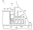
- FIG. 7 is an enlarged cross-sectional view showing the rectifying section 305 and its surroundings of the film forming apparatus 300 according to the third embodiment. The following description will focus on differences from the film forming apparatus 200 according to the second embodiment.
- the film forming apparatus 300 includes a die 102 , a cooling section 104 , a straightening section 305 , a pair of guide sections 106 , a take-up machine 108 and a winder 110 .
- the display of the pair of guide parts 106, take-up machine 108 and winder 110 is omitted.
- the rectifying section 305 includes at least one (plurality in this example) regulating plate 220 and at least one (plurality in this example) communicating passage 104e that constitutes a suction section.
- Each of the plurality of communication passages 104e vertically penetrates the upper wall 104d of the supply passage 104b, and communicates each of the plurality of spaces 250b to 250d partitioned by the current plate 220 with the supply passage 104b of the cooling unit 104. do.
- the plurality of communication paths 104e extend linearly in the vertical direction. In other words, the plurality of communicating paths 104e extend linearly, and the extending direction of the communicating paths 104e and the extending direction of the supply channel 104b are orthogonal.
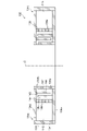
- FIGS. 8(a) and (b) are top views showing examples of the communication path 104e.
- the communication path 104e is formed in a groove shape extending in the circumferential direction in plan view.
- the communicating path 104e is a circular hole in plan view.
- Each of the plurality of spaces 250b to 250d may be communicated with one communicating path 104e as shown in FIG. 8(a), or may be communicated with a plurality of communicating paths 104e as shown in FIG. 8(b).
- the communication path 104e may be formed to a size that prevents the cooling air from flowing into the communication path 104e from the supply flow path 104b based on experiments, simulations, and the like.
- the supply channel 104b may be formed to have a channel area (that is, height) capable of realizing a desired flow velocity.
- FIG. 9 is an enlarged cross-sectional view showing a rectifying section 305 and its surroundings of a film forming apparatus 300 according to a modification of the third embodiment.
- FIG. 9 corresponds to FIG.
- the plurality of communicating paths 104e extend linearly, and the angle ⁇ formed by the extending direction D1 of the supply channel 104b and the extending direction D2 of the communicating paths 104e is greater than 90°. According to this modification, it is possible to prevent the cooling air that flows radially inward through the supply passage 104b toward the blowout portion 104c from flowing into the communication passage 104e.
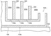
- FIG. 10 is a diagram showing the periphery of the discharge port 102a of the die 102 of the film forming apparatus 300 according to another modification of the third embodiment.
- FIG. 10 corresponds to FIG.
- the plurality of communicating paths 104e are formed in a straight line in the vertical direction, and the communicating paths 104e are formed so as to become wider toward the upper side.
- the cooling air is less likely to flow from the supply flow path 104b into the communicating path 104e, and more likely to flow into the communicating path 104e from the spaces 250b to 250d.
- the communication path 104e may be wider toward the upper side, and may be formed such that the angle ⁇ between the extending direction of the communicating path 104e and the extending direction of the supply channel 104b is greater than 90°.
- the discharge port 102a of the die 102 is a so-called round die has been described, but it is not limited to this. At least part of the technical ideas of the embodiments can also be applied to a so-called T-die having a straight ejection port.
- the present invention relates to a film forming apparatus.
Landscapes
- Engineering & Computer Science (AREA)
- Mechanical Engineering (AREA)
- Physics & Mathematics (AREA)
- Thermal Sciences (AREA)
- Manufacturing & Machinery (AREA)
- Extrusion Moulding Of Plastics Or The Like (AREA)
- Moulding By Coating Moulds (AREA)
- Internal Circuitry In Semiconductor Integrated Circuit Devices (AREA)
- Encapsulation Of And Coatings For Semiconductor Or Solid State Devices (AREA)
Priority Applications (5)
| Application Number | Priority Date | Filing Date | Title |
|---|---|---|---|
| CN202280007793.2A CN116615324B (zh) | 2021-03-31 | 2022-03-23 | 膜成型装置 |
| JP2023511087A JPWO2022210206A1 (https=) | 2021-03-31 | 2022-03-23 | |
| KR1020237018004A KR20230163347A (ko) | 2021-03-31 | 2022-03-23 | 필름성형장치 |
| EP22780420.0A EP4316780A4 (en) | 2021-03-31 | 2022-03-23 | FILM MOLDING DEVICE |
| US18/329,612 US12257759B2 (en) | 2021-03-31 | 2023-06-06 | Film molding device |
Applications Claiming Priority (2)
| Application Number | Priority Date | Filing Date | Title |
|---|---|---|---|
| JP2021-060747 | 2021-03-31 | ||
| JP2021060747 | 2021-03-31 |
Related Child Applications (1)
| Application Number | Title | Priority Date | Filing Date |
|---|---|---|---|
| US18/329,612 Continuation US12257759B2 (en) | 2021-03-31 | 2023-06-06 | Film molding device |
Publications (1)
| Publication Number | Publication Date |
|---|---|
| WO2022210206A1 true WO2022210206A1 (ja) | 2022-10-06 |
Family
ID=83456789
Family Applications (1)
| Application Number | Title | Priority Date | Filing Date |
|---|---|---|---|
| PCT/JP2022/013699 Ceased WO2022210206A1 (ja) | 2021-03-31 | 2022-03-23 | フィルム成形装置 |
Country Status (7)
| Country | Link |
|---|---|
| US (1) | US12257759B2 (https=) |
| EP (1) | EP4316780A4 (https=) |
| JP (1) | JPWO2022210206A1 (https=) |
| KR (1) | KR20230163347A (https=) |
| CN (1) | CN116615324B (https=) |
| TW (1) | TWI812129B (https=) |
| WO (1) | WO2022210206A1 (https=) |
Families Citing this family (1)
| Publication number | Priority date | Publication date | Assignee | Title |
|---|---|---|---|---|
| JP2024059219A (ja) * | 2022-10-18 | 2024-05-01 | 住友重機械工業株式会社 | 制御装置、制御方法、プログラム、計測方法、および成形システム、 |
Citations (9)
| Publication number | Priority date | Publication date | Assignee | Title |
|---|---|---|---|---|
| JPS5859069A (ja) * | 1981-10-05 | 1983-04-07 | Showa Denko Kk | インフレ−シヨンフイルム成形装置 |
| JPH06872A (ja) * | 1992-06-23 | 1994-01-11 | Mitsubishi Petrochem Co Ltd | インフレーションフィルム成形用冷却装置 |
| JPH068320A (ja) * | 1992-06-25 | 1994-01-18 | Mitsubishi Petrochem Co Ltd | 包装用樹脂フィルム |
| JPH0760833A (ja) * | 1993-08-23 | 1995-03-07 | Mitsubishi Chem Corp | インフレーション樹脂フィルムの成形方法 |
| JPH0834053A (ja) * | 1994-07-22 | 1996-02-06 | Mitsubishi Chem Corp | 延伸樹脂フィルムの製造方法 |
| JPH0839667A (ja) * | 1994-08-01 | 1996-02-13 | Mitsubishi Chem Corp | 二軸延伸樹脂フィルムの製造方法 |
| JPH08290457A (ja) * | 1995-02-24 | 1996-11-05 | Tomy Kikai Kogyo Kk | 押出成型装置の冷却媒体供給装置およびこれに用いられる層流形成部材 |
| JPH08290458A (ja) * | 1995-02-24 | 1996-11-05 | Tomy Kikai Kogyo Kk | 押出成型装置の冷却媒体供給装置 |
| JP2017177348A (ja) | 2016-03-28 | 2017-10-05 | 住友重機械モダン株式会社 | フィルム成形装置 |
Family Cites Families (21)
| Publication number | Priority date | Publication date | Assignee | Title |
|---|---|---|---|---|
| JPS5464563A (en) * | 1977-11-02 | 1979-05-24 | Tokuyama Soda Co Ltd | Production of tubular synthetic resin film |
| JPS563136Y2 (https=) * | 1978-06-09 | 1981-01-23 | ||
| JPS5894433A (ja) * | 1981-12-01 | 1983-06-04 | Nippon Petrochem Co Ltd | インフレ−シヨンフイルムの成形法 |
| EP0121158B1 (de) * | 1983-03-31 | 1986-12-17 | Windmöller & Hölscher | Kühlvorrichtung für aus einem Folienblaskopf extrudierte Kunststoffschlauchfolien |
| JPS6127239A (ja) * | 1984-07-19 | 1986-02-06 | Asahi Chem Ind Co Ltd | インフレ−シヨンフイルム製造用冷却リング |
| JPS6144624A (ja) * | 1984-08-09 | 1986-03-04 | Tounen Sekiyu Kagaku Kk | チユ−ブラ製膜の空冷装置 |
| WO1990015707A1 (de) * | 1989-06-21 | 1990-12-27 | Stefan Konermann | Verfahren und vorrichtung zur blasfolienherstellung |
| EP0544098B1 (en) | 1991-11-27 | 1998-08-12 | Mitsubishi Chemical Corporation | Polyolefin-based wrapping film |
| JPH0691752A (ja) * | 1992-09-16 | 1994-04-05 | Mitsubishi Petrochem Co Ltd | インフレーションフィルムの成形方法 |
| JP3521926B2 (ja) * | 1993-01-20 | 2004-04-26 | 新日本石油化学株式会社 | インフレーションフィルム成形装置 |
| JPH0847973A (ja) * | 1994-08-04 | 1996-02-20 | Mitsubishi Chem Corp | インフレーション二軸延伸樹脂フィルムの製造方法 |
| DE10355809A1 (de) * | 2003-11-28 | 2005-06-09 | Bayer Ag | Vorrichtung und Verfahren zur Herstellung von Blasfolien |
| EP1736297B1 (de) * | 2005-06-23 | 2008-12-17 | Kdesign GmbH | Steuerbarer Kühlgasring mit Gleichrichtereinheit |
| TWI277503B (en) * | 2005-08-25 | 2007-04-01 | Akira Shimizu | Inflation film producing device |
| JP2010247453A (ja) * | 2009-04-16 | 2010-11-04 | Du Pont Mitsui Polychem Co Ltd | インフレーション成形装置 |
| CN202137947U (zh) * | 2011-03-29 | 2012-02-08 | 东莞市正新包装制品有限公司 | 一种薄膜吹塑机的冷却装置 |
| EP3398750B1 (en) * | 2015-12-28 | 2021-10-20 | Toray Industries, Inc. | Airflow control apparatus and method for manufacturing stretched film |
| JP6948281B2 (ja) * | 2018-03-30 | 2021-10-13 | 住友重機械工業株式会社 | フィルム成形装置 |
| CN110065225B (zh) * | 2019-05-31 | 2021-03-16 | 重庆瑞霆塑胶有限公司 | 塑料薄膜吹塑设备 |
| CN211467144U (zh) * | 2019-12-16 | 2020-09-11 | 江苏普雷特塑料包装有限公司 | 薄膜吹塑机用薄膜冷却装置 |
| CN111516250A (zh) * | 2020-04-30 | 2020-08-11 | 辛集市旭远新材料科技有限公司 | 一种复合塑料薄膜吹膜机以及制备方法 |
-
2022
- 2022-03-23 EP EP22780420.0A patent/EP4316780A4/en active Pending
- 2022-03-23 KR KR1020237018004A patent/KR20230163347A/ko active Pending
- 2022-03-23 WO PCT/JP2022/013699 patent/WO2022210206A1/ja not_active Ceased
- 2022-03-23 JP JP2023511087A patent/JPWO2022210206A1/ja active Pending
- 2022-03-23 CN CN202280007793.2A patent/CN116615324B/zh active Active
- 2022-03-30 TW TW111112083A patent/TWI812129B/zh active
-
2023
- 2023-06-06 US US18/329,612 patent/US12257759B2/en active Active
Patent Citations (9)
| Publication number | Priority date | Publication date | Assignee | Title |
|---|---|---|---|---|
| JPS5859069A (ja) * | 1981-10-05 | 1983-04-07 | Showa Denko Kk | インフレ−シヨンフイルム成形装置 |
| JPH06872A (ja) * | 1992-06-23 | 1994-01-11 | Mitsubishi Petrochem Co Ltd | インフレーションフィルム成形用冷却装置 |
| JPH068320A (ja) * | 1992-06-25 | 1994-01-18 | Mitsubishi Petrochem Co Ltd | 包装用樹脂フィルム |
| JPH0760833A (ja) * | 1993-08-23 | 1995-03-07 | Mitsubishi Chem Corp | インフレーション樹脂フィルムの成形方法 |
| JPH0834053A (ja) * | 1994-07-22 | 1996-02-06 | Mitsubishi Chem Corp | 延伸樹脂フィルムの製造方法 |
| JPH0839667A (ja) * | 1994-08-01 | 1996-02-13 | Mitsubishi Chem Corp | 二軸延伸樹脂フィルムの製造方法 |
| JPH08290457A (ja) * | 1995-02-24 | 1996-11-05 | Tomy Kikai Kogyo Kk | 押出成型装置の冷却媒体供給装置およびこれに用いられる層流形成部材 |
| JPH08290458A (ja) * | 1995-02-24 | 1996-11-05 | Tomy Kikai Kogyo Kk | 押出成型装置の冷却媒体供給装置 |
| JP2017177348A (ja) | 2016-03-28 | 2017-10-05 | 住友重機械モダン株式会社 | フィルム成形装置 |
Non-Patent Citations (1)
| Title |
|---|
| See also references of EP4316780A4 |
Also Published As
| Publication number | Publication date |
|---|---|
| EP4316780A4 (en) | 2024-08-28 |
| EP4316780A1 (en) | 2024-02-07 |
| JPWO2022210206A1 (https=) | 2022-10-06 |
| KR20230163347A (ko) | 2023-11-30 |
| CN116615324B (zh) | 2026-01-02 |
| US20230311400A1 (en) | 2023-10-05 |
| TWI812129B (zh) | 2023-08-11 |
| CN116615324A (zh) | 2023-08-18 |
| US12257759B2 (en) | 2025-03-25 |
| TW202239569A (zh) | 2022-10-16 |
Similar Documents
| Publication | Publication Date | Title |
|---|---|---|
| JP2004183964A (ja) | エアシャワ装置 | |
| WO2022210206A1 (ja) | フィルム成形装置 | |
| CN111826729B (zh) | 熔融纺丝设备 | |
| US4373273A (en) | Air ring having a circular array of a large multiplicity of substantially parallel cell-like passages in the air flow path leading to the outlet | |
| CN101468365B (zh) | 导风装置和采用该导风装置的工件冷却装置 | |
| TWI606865B (zh) | 基板處理裝置 | |
| CN109605720B (zh) | 塑料吹膜机内冷结构 | |
| CN111304594A (zh) | 真空装置及真空镀膜设备 | |
| CN211134815U (zh) | 一种环形吹气清洁装置 | |
| CN207549470U (zh) | 一种用于吹膜设备的冷却风分配装置 | |
| CN212270215U (zh) | 真空装置及真空镀膜设备 | |
| JP3521926B2 (ja) | インフレーションフィルム成形装置 | |
| CN211968403U (zh) | 一种薄膜吹塑成型装置 | |
| CN211891949U (zh) | 一种高效高产能吹膜机冷却风环 | |
| CN210415196U (zh) | 一种用于流延膜机的真空箱 | |
| JP2501296Y2 (ja) | ゾ―ン形成装置 | |
| CN121133086B (zh) | 塑料吹膜机内冷结构 | |
| CN215849609U (zh) | 一种能够精准控制地膜膜径的吹膜系统 | |
| JPH0517228Y2 (https=) | ||
| JPH0114421Y2 (https=) | ||
| CN221951613U (zh) | 一种带纠偏的气浮辊 | |
| JPH0230267Y2 (https=) | ||
| TW202436804A (zh) | 流體排放裝置 | |
| EP4519060A1 (en) | Cooling ring for an apparatus for the production of plastic blown films | |
| KR20130000047A (ko) | 송풍안내부재 및 이를 갖춘 송풍안내장치 |
Legal Events
| Date | Code | Title | Description |
|---|---|---|---|
| 121 | Ep: the epo has been informed by wipo that ep was designated in this application |
Ref document number: 22780420 Country of ref document: EP Kind code of ref document: A1 |
|
| ENP | Entry into the national phase |
Ref document number: 2023511087 Country of ref document: JP Kind code of ref document: A |
|
| WWE | Wipo information: entry into national phase |
Ref document number: 202280007793.2 Country of ref document: CN |
|
| WWE | Wipo information: entry into national phase |
Ref document number: 2022780420 Country of ref document: EP |
|
| ENP | Entry into the national phase |
Ref document number: 2022780420 Country of ref document: EP Effective date: 20231031 |
|
| NENP | Non-entry into the national phase |
Ref country code: DE |