WO2022209870A1 - 車輪モジュール - Google Patents
車輪モジュール Download PDFInfo
- Publication number
- WO2022209870A1 WO2022209870A1 PCT/JP2022/011715 JP2022011715W WO2022209870A1 WO 2022209870 A1 WO2022209870 A1 WO 2022209870A1 JP 2022011715 W JP2022011715 W JP 2022011715W WO 2022209870 A1 WO2022209870 A1 WO 2022209870A1
- Authority
- WO
- WIPO (PCT)
- Prior art keywords
- tire
- wheel module
- steering
- suspension mechanism
- wheel
- Prior art date
- Legal status (The legal status is an assumption and is not a legal conclusion. Google has not performed a legal analysis and makes no representation as to the accuracy of the status listed.)
- Ceased
Links
Images


Classifications
-
- B—PERFORMING OPERATIONS; TRANSPORTING
- B60—VEHICLES IN GENERAL
- B60G—VEHICLE SUSPENSION ARRANGEMENTS
- B60G3/00—Resilient suspensions for a single wheel
- B60G3/02—Resilient suspensions for a single wheel with a single pivoted arm
-
- B—PERFORMING OPERATIONS; TRANSPORTING
- B60—VEHICLES IN GENERAL
- B60G—VEHICLE SUSPENSION ARRANGEMENTS
- B60G3/00—Resilient suspensions for a single wheel
- B60G3/02—Resilient suspensions for a single wheel with a single pivoted arm
- B60G3/12—Resilient suspensions for a single wheel with a single pivoted arm the arm being essentially parallel to the longitudinal axis of the vehicle
- B60G3/14—Resilient suspensions for a single wheel with a single pivoted arm the arm being essentially parallel to the longitudinal axis of the vehicle the arm being rigid
- B60G3/145—Resilient suspensions for a single wheel with a single pivoted arm the arm being essentially parallel to the longitudinal axis of the vehicle the arm being rigid the arm forming the axle housing
-
- B—PERFORMING OPERATIONS; TRANSPORTING
- B60—VEHICLES IN GENERAL
- B60G—VEHICLE SUSPENSION ARRANGEMENTS
- B60G15/00—Resilient suspensions characterised by arrangement, location or type of combined spring and vibration damper, e.g. telescopic type
- B60G15/02—Resilient suspensions characterised by arrangement, location or type of combined spring and vibration damper, e.g. telescopic type having mechanical spring
-
- B—PERFORMING OPERATIONS; TRANSPORTING
- B60—VEHICLES IN GENERAL
- B60G—VEHICLE SUSPENSION ARRANGEMENTS
- B60G3/00—Resilient suspensions for a single wheel
- B60G3/18—Resilient suspensions for a single wheel with two or more pivoted arms, e.g. parallelogram
- B60G3/20—Resilient suspensions for a single wheel with two or more pivoted arms, e.g. parallelogram all arms being rigid
-
- B—PERFORMING OPERATIONS; TRANSPORTING
- B60—VEHICLES IN GENERAL
- B60K—ARRANGEMENT OR MOUNTING OF PROPULSION UNITS OR OF TRANSMISSIONS IN VEHICLES; ARRANGEMENT OR MOUNTING OF PLURAL DIVERSE PRIME-MOVERS IN VEHICLES; AUXILIARY DRIVES FOR VEHICLES; INSTRUMENTATION OR DASHBOARDS FOR VEHICLES; ARRANGEMENTS IN CONNECTION WITH COOLING, AIR INTAKE, GAS EXHAUST OR FUEL SUPPLY OF PROPULSION UNITS IN VEHICLES
- B60K7/00—Disposition of motor in, or adjacent to, traction wheel
- B60K7/0007—Disposition of motor in, or adjacent to, traction wheel the motor being electric
-
- B—PERFORMING OPERATIONS; TRANSPORTING
- B62—LAND VEHICLES FOR TRAVELLING OTHERWISE THAN ON RAILS
- B62D—MOTOR VEHICLES; TRAILERS
- B62D5/00—Power-assisted or power-driven steering
- B62D5/04—Power-assisted or power-driven steering electrical, e.g. using an electric servo-motor connected to, or forming part of, the steering gear
- B62D5/0457—Power-assisted or power-driven steering electrical, e.g. using an electric servo-motor connected to, or forming part of, the steering gear characterised by control features of the drive means as such
- B62D5/046—Controlling the motor
-
- B—PERFORMING OPERATIONS; TRANSPORTING
- B62—LAND VEHICLES FOR TRAVELLING OTHERWISE THAN ON RAILS
- B62D—MOTOR VEHICLES; TRAILERS
- B62D7/00—Steering linkage; Stub axles or their mountings
- B62D7/06—Steering linkage; Stub axles or their mountings for individually-pivoted wheels, e.g. on king-pins
- B62D7/14—Steering linkage; Stub axles or their mountings for individually-pivoted wheels, e.g. on king-pins the pivotal axes being situated in more than one plane transverse to the longitudinal centre line of the vehicle, e.g. all-wheel steering
-
- B—PERFORMING OPERATIONS; TRANSPORTING
- B60—VEHICLES IN GENERAL
- B60G—VEHICLE SUSPENSION ARRANGEMENTS
- B60G2200/00—Indexing codes relating to suspension types
- B60G2200/10—Independent suspensions
- B60G2200/13—Independent suspensions with longitudinal arms only
- B60G2200/132—Independent suspensions with longitudinal arms only with a single trailing arm
-
- B—PERFORMING OPERATIONS; TRANSPORTING
- B60—VEHICLES IN GENERAL
- B60G—VEHICLE SUSPENSION ARRANGEMENTS
- B60G2200/00—Indexing codes relating to suspension types
- B60G2200/40—Indexing codes relating to the wheels in the suspensions
- B60G2200/44—Indexing codes relating to the wheels in the suspensions steerable
-
- B—PERFORMING OPERATIONS; TRANSPORTING
- B60—VEHICLES IN GENERAL
- B60G—VEHICLE SUSPENSION ARRANGEMENTS
- B60G2202/00—Indexing codes relating to the type of spring, damper or actuator
- B60G2202/10—Type of spring
- B60G2202/12—Wound spring
-
- B—PERFORMING OPERATIONS; TRANSPORTING
- B60—VEHICLES IN GENERAL
- B60G—VEHICLE SUSPENSION ARRANGEMENTS
- B60G2202/00—Indexing codes relating to the type of spring, damper or actuator
- B60G2202/30—Spring/Damper and/or actuator Units
- B60G2202/31—Spring/Damper and/or actuator Units with the spring arranged around the damper, e.g. MacPherson strut
- B60G2202/312—The spring being a wound spring
-
- B—PERFORMING OPERATIONS; TRANSPORTING
- B60—VEHICLES IN GENERAL
- B60G—VEHICLE SUSPENSION ARRANGEMENTS
- B60G2204/00—Indexing codes related to suspensions per se or to auxiliary parts
- B60G2204/10—Mounting of suspension elements
- B60G2204/30—In-wheel mountings
-
- B—PERFORMING OPERATIONS; TRANSPORTING
- B60—VEHICLES IN GENERAL
- B60G—VEHICLE SUSPENSION ARRANGEMENTS
- B60G2206/00—Indexing codes related to the manufacturing of suspensions: constructional features, the materials used, procedures or tools
- B60G2206/01—Constructional features of suspension elements, e.g. arms, dampers, springs
- B60G2206/011—Modular constructions
- B60G2206/0114—Independent suspensions on subframes
-
- B—PERFORMING OPERATIONS; TRANSPORTING
- B60—VEHICLES IN GENERAL
- B60G—VEHICLE SUSPENSION ARRANGEMENTS
- B60G2300/00—Indexing codes relating to the type of vehicle
- B60G2300/37—Vehicles having steerable wheels mounted on a vertically moving column
-
- B—PERFORMING OPERATIONS; TRANSPORTING
- B60—VEHICLES IN GENERAL
- B60G—VEHICLE SUSPENSION ARRANGEMENTS
- B60G2300/00—Indexing codes relating to the type of vehicle
- B60G2300/50—Electric vehicles; Hybrid vehicles
-
- B—PERFORMING OPERATIONS; TRANSPORTING
- B60—VEHICLES IN GENERAL
- B60K—ARRANGEMENT OR MOUNTING OF PROPULSION UNITS OR OF TRANSMISSIONS IN VEHICLES; ARRANGEMENT OR MOUNTING OF PLURAL DIVERSE PRIME-MOVERS IN VEHICLES; AUXILIARY DRIVES FOR VEHICLES; INSTRUMENTATION OR DASHBOARDS FOR VEHICLES; ARRANGEMENTS IN CONNECTION WITH COOLING, AIR INTAKE, GAS EXHAUST OR FUEL SUPPLY OF PROPULSION UNITS IN VEHICLES
- B60K7/00—Disposition of motor in, or adjacent to, traction wheel
- B60K2007/0038—Disposition of motor in, or adjacent to, traction wheel the motor moving together with the wheel axle
-
- B—PERFORMING OPERATIONS; TRANSPORTING
- B60—VEHICLES IN GENERAL
- B60K—ARRANGEMENT OR MOUNTING OF PROPULSION UNITS OR OF TRANSMISSIONS IN VEHICLES; ARRANGEMENT OR MOUNTING OF PLURAL DIVERSE PRIME-MOVERS IN VEHICLES; AUXILIARY DRIVES FOR VEHICLES; INSTRUMENTATION OR DASHBOARDS FOR VEHICLES; ARRANGEMENTS IN CONNECTION WITH COOLING, AIR INTAKE, GAS EXHAUST OR FUEL SUPPLY OF PROPULSION UNITS IN VEHICLES
- B60K7/00—Disposition of motor in, or adjacent to, traction wheel
- B60K2007/0092—Disposition of motor in, or adjacent to, traction wheel the motor axle being coaxial to the wheel axle
-
- B—PERFORMING OPERATIONS; TRANSPORTING
- B62—LAND VEHICLES FOR TRAVELLING OTHERWISE THAN ON RAILS
- B62D—MOTOR VEHICLES; TRAILERS
- B62D5/00—Power-assisted or power-driven steering
- B62D5/04—Power-assisted or power-driven steering electrical, e.g. using an electric servo-motor connected to, or forming part of, the steering gear
- B62D5/0418—Electric motor acting on road wheel carriers
-
- B—PERFORMING OPERATIONS; TRANSPORTING
- B62—LAND VEHICLES FOR TRAVELLING OTHERWISE THAN ON RAILS
- B62D—MOTOR VEHICLES; TRAILERS
- B62D7/00—Steering linkage; Stub axles or their mountings
- B62D7/02—Steering linkage; Stub axles or their mountings for pivoted bogies
- B62D7/023—Steering turntables
Definitions
- the present disclosure relates to wheel modules.
- the steering apparatus for an in-wheel motor vehicle disclosed in Patent Document 1 aims at avoiding an unnecessary increase in size even if a damper is added, and transmitting a sufficiently large rotational torque.
- the outer shaft housing the shock absorber is arranged on the central axis of the in-wheel motor unit. That is, when the wheel side is viewed as the front, the spring of the shock absorber is arranged vertically on the central axis of the tire in the vertical direction. Therefore, the shock from the road surface is transmitted directly to the spring, which deteriorates the ride comfort.
- An object of the present disclosure is to provide a wheel module that improves ride comfort in a wheel module that constitutes independently steered wheels of a vehicle.
- the wheel module of the present disclosure is used in a vehicle that includes two or more independently steerable wheels, and constitutes the independently steerable wheels.
- This wheel module includes tires, a steering section, a driving section, a braking section, and a suspension mechanism.
- the surface with sidewalls is defined as the side surface, and the tread surface facing the front of the vehicle is defined as the front surface.
- the steering section outputs a steering force for steering the tires.
- the driving unit outputs driving force for driving the tire.
- the braking section outputs a braking force for braking the tire.
- the suspension mechanism is supported by an upper fulcrum and a lower fulcrum, and absorbs vibrations or shocks transmitted from the road surface.
- An imaginary straight line in the vertical direction that passes through the center in the radial direction and the center in the width direction of the tire is defined as the center axis of the tire.
- the lower end side fulcrum of the suspension mechanism is arranged at a position away from the central axis of the tire.
- the suspension mechanism is inclined with respect to the central axis of the tire when viewed from the side of the tire.
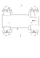
- FIG. 1 is a plan view of an independently steered vehicle using a wheel module of one embodiment
- 2 is a side view of the independently steered vehicle of FIG. 1
- FIG. 3 is a perspective view of an embodiment wheel module
- FIG. 4 is a view in the direction of arrow IV in FIG. 3 (a view seen from the inner surface of the tire)
- 5 is a view in the direction of arrow V in FIG. 3 (view from the front of the tire)
- 6 is a view in the direction of arrow VI in FIG. 3
- FIG. 7 is a diagram showing the configuration of a multi-winding motor in a steered motor
- FIG. 8 is a diagram for explaining the rotation operation about the arm connecting shaft
- FIG. 9 is a schematic diagram for explaining the compression operation of the suspension mechanism during upward rotation
- FIG. 10 is a schematic diagram illustrating the extension operation of the suspension mechanism during downward rotation.
- a wheel module according to one embodiment will be described based on the drawings.
- the wheel module of the present disclosure is used in a vehicle including two or more independently steerable wheels, and constitutes the independently steerable wheels.
- a configuration example in which four wheel modules are used in a four-wheeled vehicle in which all wheels are independently steered wheels is shown.
- the steering and braking/driving commands will be explained assuming manual operation by the driver.
- FIG. 1 schematically shows an arrangement configuration of a vehicle body 99 and four wheels 91, 92, 93, and 94 in a four-wheel independent steering vehicle 90 as viewed from above.
- the four wheels are a left front wheel 91, a right front wheel 92, a left rear wheel 93 and a right rear wheel 94, respectively.
- Each wheel 91 to 94 is an independently steerable wheel, and is composed of the wheel module 10 .
- the center point of each wheel module 10 represents the tire center axis Zt. A detailed definition of the tire central axis Zt will be described later.
- FIG. 2 schematically shows a state in which the front wheels 92 and the rear wheels 94 are viewed from the right side of the vehicle 90.
- the reference numeral of the wheel module for the front wheel 92 is "10F”
- the reference numeral of the wheel module for the rear wheel 94 is "10R”.
- the wheel modules 10F and 10R including those for the left wheels form independent steerable wheels in the front wheels 91 and 92 and the rear wheels 93 and 94 of the vehicle 90.
- the wheel module 10F for the front wheels 92 and the wheel module 10R for the rear wheels 94 are symmetrical in the longitudinal direction with respect to the tire central axis Zt. there is That is, in the wheel module 10F for the front wheel 92, the suspension mechanism 7 is provided on the front side of the vehicle 90 with respect to the tire central axis Zt. In the wheel module 10R for the rear wheel 94, the suspension mechanism 7 is provided on the rear side of the vehicle 90 with respect to the tire central axis Zt.
- the suspension mechanism 7 is inclined so that the upper end side approaches the tire center axis Zt and the lower end side separates from the tire center axis Zt. Therefore, the suspension mechanisms 7 for the front and rear wheels 92, 94 are arranged so that the distance between them increases from top to bottom.
- a vehicle in which each wheel can be steered independently eliminates the space required for the rack bar, increasing the interior space.
- the degree of freedom of movement is improved, such as entering and turning narrow roads and parking in narrow spaces.
- each independently steered wheel is configured as a wheel module equipped with a steering mechanism, an in-wheel motor that is a drive mechanism, and an electric brake that is a braking mechanism.
- a steering mechanism that is a steering mechanism
- an in-wheel motor that is a drive mechanism
- an electric brake that is a braking mechanism.
- the main purpose is to improve riding comfort, and a wheel module that is advantageous in expanding the cabin space and improving resistance to external disturbances is provided.
- the wheel module 10F for the front wheels and the wheel module 10R for the rear wheels are applied to any independent steerable wheel, except that they are symmetrical with respect to the tire center axis Zt.
- the basic configuration of each wheel module is the same.
- one form of "wheel module 10" will be described without distinguishing between the front wheel module and the rear wheel module.
- FIG. 4 is a view of the wheel module 10 that constitutes the left front wheel 91 of FIG. 1, viewed from the inside.
- the three-dimensional axis of the tire 2 is defined with the left-right direction of the vehicle when traveling straight ahead as the X direction, the front-rear direction as the Y direction, and the height direction as the Z direction.
- a virtual straight line passing through the radial center of the tire 2 is defined as a wheel axis Xt.
- An imaginary straight line passing through the radial center of the tire 2 in the horizontal direction and in the longitudinal direction of the vehicle is defined as a front-rear axis Yt.
- An imaginary straight line in the vertical direction passing through the center in the radial direction and the center in the width direction of the tire 2 is defined as a tire center axis Zt.
- the wheel module 10 includes a tire 2, a steering section 3, an arm 4, a driving section 5, a braking section 6, and a suspension mechanism 7.
- the steering unit 3 outputs a steering force for steering the tires 2 according to the driver's steering operation.
- the steering unit 3 includes a steering motor 31 that outputs torque, and a speed reducer 32 that reduces rotation of the steering motor 31 and transmits the reduced rotation to the arm 4 .
- the steering motor 31 and the speed reducer 32 are stacked on the tire central axis Zt. By increasing the speed reduction ratio of the speed reducer 32, the steering portion 3 is made compact.
- the steering motor 31 of one embodiment is composed of a double-winding motor that redundantly has two sets of three-phase winding sets 311 and 312 .
- the other winding set can be energized, thereby improving reliability.
- the arm 4 connects the steering section 3 and the tire 2 .
- a steering force output by the steering portion 3 is transmitted to the tire 2 via the arm 4 .
- the arm 4 includes an upper arm 41 on the steering portion 3 side and a rocker arm 45 on the tire 2 side.
- the upper arm 41 includes a top plate portion 42 , a body portion 43 and a top plate extension portion 44 .
- the top plate portion 42 is provided directly above the tire 2 on the tire center axis Zt and connected to the steering portion 3 .
- the body portion 43 extends from the upper portion of the tire 2 to below the front-rear axis Yt on one side (the left side in FIG. 4) of the tire central axis Zt.
- the top plate extension portion 44 extends from the top plate portion 42 in a direction opposite to the main body portion 43 and supports the upper end side fulcrum SU of the suspension mechanism 7 .
- the upper arm 41 and the rocker arm 45 are rotatably connected about a horizontal arm connecting axis Xa. As shown in FIG. 4, when viewed from the side of the tire 2, the arm connecting axis Xa is separated from the tire central axis Zt.
- the rocker arm 45 has a connecting end portion 46 provided around the arm connecting axis Xa, a central portion 47 provided around the wheel axis Xt, and a side opposite to the connecting end portion 46 with respect to the central portion 47. It includes a free end 48 which is tapered. The free end portion 48 supports the lower end side fulcrum SL of the suspension mechanism 7 .
- the driving unit 5 is composed of an in-wheel motor, and outputs a driving force for driving the tires 2 according to the driver's accelerator operation and the like.
- the braking unit 6 is composed of an electric or hydraulic brake, and outputs a braking force for braking the tires 2 according to the driver's brake operation or the like.
- the suspension mechanism 7 is supported by the upper end side fulcrum SU and the lower end side fulcrum SL, and absorbs vibrations or shocks transmitted from the road surface.
- the suspension mechanism 7 includes a damper 71 , which is a rod-shaped cushioning member, and a coil-shaped spring 72 fitted around the damper 71 .
- a center axis of the damper 71 and the spring 72 is defined as a suspension mechanism axis YZs.
- the symbol "YZs" means an axis parallel to the YZ plane including the front-rear axis Yt of the tire 2 and the tire center axis Zt.
- about 70% of the suspension mechanism 7 in the axial direction is arranged inside the radial outer edge of the tire 2 .
- the suspension mechanism 7 in the axial direction is arranged inside the radial outer edge of the tire 2, so that the vehicle interior space can be expanded.
- the lower end side fulcrum SL of the suspension mechanism 7 is arranged at a position away from the tire central axis Zt. Further, the suspension mechanism axis YZs is inclined with respect to the tire central axis Zt.
- the spring of the shock absorber is arranged vertically on the central axis of the tire in the vertical direction, so that the shock from the road surface is absorbed by the spring. directly transmitted to the vehicle and deteriorates the ride comfort.
- the suspension mechanism 7 is tilted away from the tire center axis Zt, so that the impact from the road surface is less likely to be directly transmitted to the spring 72 . Therefore, it is possible to suppress the occurrence of unpleasant vibrations when subjected to disturbances in the vertical direction due to bumps on the road surface, stones, etc., and to improve ride comfort.
- the upper fulcrum SU of the suspension mechanism 7 is rotatably supported by the top plate extension 44 of the upper arm 41 . Further, the lower end side fulcrum SL is rotatably supported by the free end portion 48 of the rocker arm 45 .
- the lower end side fulcrum SL of the suspension mechanism 7 is rotatable within a plane parallel to the side surface of the tire 2 around the arm connecting axis Xa. In the initial state shown in FIG. 4, the wheel axis Xt and the lower end side fulcrum SL are at the same height and arranged at a position higher than the arm connecting axis Xa.
- FIG. 8 shows a raised state in which the tire 2 rotates upward about the arm connecting axis Xa from the initial state indicated by the solid line, and a lowered state in which the tire 2 rotates downward.
- the amount of rotation is shown larger than the actual amount for explanation.
- the wheel axis Xt moves along an arc locus with a radius of r1.
- the vehicle body is pulled down, and when the tires 2 are lowered, the vehicle body is lifted.
- the lower end side fulcrum SL of the suspension mechanism 7 moves along an arc locus with a radius of r2.
- FIG. 9 and 10 schematically show the positional relationship among the tire 2, upper arm 41, rocker arm 45, and suspension mechanism 7.
- FIG. The positions of the upper arm 41 and the upper end support portion SU of the suspension mechanism 7 do not change.
- FIG. 9 when the tire 2 receives an upward force from the road surface and the wheel shaft Xt rotates upward, the position of the lower end support portion SL rises and the spring 72 of the suspension mechanism 7 is compressed.
- FIG. 10 when the tire 2 receives a downward force from the road surface and the wheel shaft Xt rotates downward, the position of the lower end support portion SL is lowered and the spring 72 of the suspension mechanism 7 is extended.
- the suspension mechanism 7 rotates the lower end side fulcrum SL supported by the rocker arm 45 around the arm connecting axis Xa according to the force that the tire 2 receives from the road surface, thereby reducing the vibration or impact transmitted from the road surface.
- the force directly transmitted from the road surface is determined by the ratio between the rotation radius r1 of the wheel axis Xt and the rotation radius r2 of the lower end side fulcrum SL. is attenuated and transmitted to the suspension mechanism 7 . Therefore, as described above, it is possible to suppress the occurrence of unpleasant vibrations when subjected to disturbance from the road surface, thereby improving the ride comfort.
- the kingpin axis which is the steering center of the tire, is offset from the central axis of the tire in the width direction.
- the torque steer becomes zero by aligning the kingpin axis Zk and the tire center axis Zt and making the offset zero.
- the influence of the braking/driving force on the actual steering torque is eliminated, so that interference between the "run/turn/stop" operations can be prevented.
- the impact mark (*2) there is no influence on the actual steering torque due to disturbances such as steps and stones. Therefore, disturbance resistance is improved.
- the independently steered vehicle using the wheel module 10 is not limited to a four-wheeled vehicle, and may be a two-wheeled vehicle or a three-wheeled vehicle.
- the wheel module 10F for the front wheel has the suspension mechanism 7 provided on the front side of the vehicle with respect to the tire center axis Zt
- the wheel module 10R for the rear wheel has the suspension mechanism 7 positioned at the center of the tire. It is preferably provided on the rear side of the vehicle with respect to the axis Zt.
- not all wheels are independently steerable wheels.
- the left and right front wheels may be independently steerable wheels, and the left and right rear wheels may be connected by a rack bar.
- any vehicle including two or more independently steerable wheels can be a target vehicle for which the wheel module 10 is used.
- the specific configurations of the steering section 3, the driving section 5, and the braking section 6 are not limited to those of the above-described embodiment, and may be any configuration that realizes the respective functions.
- the steered motor 31 is not limited to a double winding motor, and may be a multiple winding motor redundantly having three or more winding sets. Alternatively, it may be composed of a motor consisting of a set of windings.
- the arm 4 is not limited to the configuration in which the upper arm 41 and the rocker arm 45 are connected, but may be one that connects the steering portion 3 and the tire 2 integrally.
- the wheel module 10 may be applied to an autonomous vehicle.
- "according to the driver's operation” in the description of the steering unit 3, the driving unit 5, and the braking unit 6 in the above embodiment should be read as "according to the automatic driving command”.
Landscapes
- Engineering & Computer Science (AREA)
- Mechanical Engineering (AREA)
- Chemical & Material Sciences (AREA)
- Combustion & Propulsion (AREA)
- Transportation (AREA)
- Vehicle Body Suspensions (AREA)
- Steering-Linkage Mechanisms And Four-Wheel Steering (AREA)
- Power Steering Mechanism (AREA)
Priority Applications (2)
| Application Number | Priority Date | Filing Date | Title |
|---|---|---|---|
| CN202280023803.1A CN117042989A (zh) | 2021-03-29 | 2022-03-15 | 车轮模块 |
| US18/476,040 US20240017579A1 (en) | 2021-03-29 | 2023-09-27 | Wheel module |
Applications Claiming Priority (2)
| Application Number | Priority Date | Filing Date | Title |
|---|---|---|---|
| JP2021-055592 | 2021-03-29 | ||
| JP2021055592A JP7569535B2 (ja) | 2021-03-29 | 2021-03-29 | 車輪モジュール |
Related Child Applications (1)
| Application Number | Title | Priority Date | Filing Date |
|---|---|---|---|
| US18/476,040 Continuation US20240017579A1 (en) | 2021-03-29 | 2023-09-27 | Wheel module |
Publications (1)
| Publication Number | Publication Date |
|---|---|
| WO2022209870A1 true WO2022209870A1 (ja) | 2022-10-06 |
Family
ID=83459043
Family Applications (1)
| Application Number | Title | Priority Date | Filing Date |
|---|---|---|---|
| PCT/JP2022/011715 Ceased WO2022209870A1 (ja) | 2021-03-29 | 2022-03-15 | 車輪モジュール |
Country Status (4)
| Country | Link |
|---|---|
| US (1) | US20240017579A1 (https=) |
| JP (1) | JP7569535B2 (https=) |
| CN (1) | CN117042989A (https=) |
| WO (1) | WO2022209870A1 (https=) |
Cited By (1)
| Publication number | Priority date | Publication date | Assignee | Title |
|---|---|---|---|---|
| CN116039304A (zh) * | 2022-12-26 | 2023-05-02 | 北理华创(佛山)新能源汽车科技有限公司 | 一种悬架导向机构及集成转向悬架驱动系统 |
Citations (5)
| Publication number | Priority date | Publication date | Assignee | Title |
|---|---|---|---|---|
| JP2003136930A (ja) * | 2001-11-08 | 2003-05-14 | Mitsui Eng & Shipbuild Co Ltd | 搬送台車の車体水平制御方法および装置 |
| JP2007230293A (ja) * | 2006-02-28 | 2007-09-13 | Equos Research Co Ltd | 車輪支持・駆動伝達装置 |
| WO2011052076A1 (ja) * | 2009-10-30 | 2011-05-05 | トヨタ自動車株式会社 | 車両運動制御システム |
| GB2490526A (en) * | 2011-05-04 | 2012-11-07 | Samuel Dantzie | A steerable wheel assembly for a vehicle, and a vehicle including such an assembly |
| JP2014210558A (ja) * | 2013-04-22 | 2014-11-13 | 日本車輌製造株式会社 | 作業車の走行装置 |
Family Cites Families (6)
| Publication number | Priority date | Publication date | Assignee | Title |
|---|---|---|---|---|
| FR2645475B1 (fr) * | 1989-04-11 | 1994-03-25 | Renault Regie Nale Usines | Suspension pour vehicules automobiles |
| JP2003261295A (ja) | 2002-03-11 | 2003-09-16 | Nippon Yusoki Co Ltd | 荷役車両 |
| JP5497645B2 (ja) * | 2008-07-10 | 2014-05-21 | 本田技研工業株式会社 | 車両用サスペンションアーム |
| US9102331B2 (en) * | 2013-09-20 | 2015-08-11 | GM Global Technology Operations LLC | Multi-functional electric module for a vehicle |
| CN104118492B (zh) * | 2014-07-11 | 2016-06-01 | 江苏海鹏特种车辆有限公司 | 超长可自装卸整体式运输车 |
| CN209649974U (zh) * | 2019-03-27 | 2019-11-19 | 威海广泰空港设备股份有限公司 | 独立悬挂可旋转180°的行走装置 |
-
2021
- 2021-03-29 JP JP2021055592A patent/JP7569535B2/ja active Active
-
2022
- 2022-03-15 WO PCT/JP2022/011715 patent/WO2022209870A1/ja not_active Ceased
- 2022-03-15 CN CN202280023803.1A patent/CN117042989A/zh active Pending
-
2023
- 2023-09-27 US US18/476,040 patent/US20240017579A1/en active Pending
Patent Citations (5)
| Publication number | Priority date | Publication date | Assignee | Title |
|---|---|---|---|---|
| JP2003136930A (ja) * | 2001-11-08 | 2003-05-14 | Mitsui Eng & Shipbuild Co Ltd | 搬送台車の車体水平制御方法および装置 |
| JP2007230293A (ja) * | 2006-02-28 | 2007-09-13 | Equos Research Co Ltd | 車輪支持・駆動伝達装置 |
| WO2011052076A1 (ja) * | 2009-10-30 | 2011-05-05 | トヨタ自動車株式会社 | 車両運動制御システム |
| GB2490526A (en) * | 2011-05-04 | 2012-11-07 | Samuel Dantzie | A steerable wheel assembly for a vehicle, and a vehicle including such an assembly |
| JP2014210558A (ja) * | 2013-04-22 | 2014-11-13 | 日本車輌製造株式会社 | 作業車の走行装置 |
Cited By (1)
| Publication number | Priority date | Publication date | Assignee | Title |
|---|---|---|---|---|
| CN116039304A (zh) * | 2022-12-26 | 2023-05-02 | 北理华创(佛山)新能源汽车科技有限公司 | 一种悬架导向机构及集成转向悬架驱动系统 |
Also Published As
| Publication number | Publication date |
|---|---|
| JP2022152722A (ja) | 2022-10-12 |
| CN117042989A (zh) | 2023-11-10 |
| US20240017579A1 (en) | 2024-01-18 |
| JP7569535B2 (ja) | 2024-10-18 |
Similar Documents
| Publication | Publication Date | Title |
|---|---|---|
| JP6004097B2 (ja) | インホイールモータ駆動車輪用サスペンション装置 | |
| EP3206897B1 (en) | Wheel suspension | |
| US9796235B2 (en) | Suspension device for in-wheel motor driven wheel | |
| CN102317134B (zh) | 导轨式车辆用转向架 | |
| US12252199B2 (en) | Independent corner module | |
| US20180334001A1 (en) | Suspension device for non-steered driving wheel incorporating in-wheel motor | |
| KR20140105710A (ko) | 차량 | |
| JP2012121391A (ja) | ステアリング装置 | |
| CN112659831B (zh) | 车辆前悬架 | |
| CN105667579A (zh) | 轮毂电机驱动电动汽车的差速转向系统及其电动汽车 | |
| JP2020048611A (ja) | 一人乗り電動車両 | |
| JP2005106106A (ja) | 車両懸架装置 | |
| KR102771525B1 (ko) | 차량용 현가 장치 | |
| WO2022209870A1 (ja) | 車輪モジュール | |
| CN106828440B (zh) | 一种适用于四驱无人矿车的爆胎安全辅助装置 | |
| CN105584530B (zh) | 一种汽车车架以及具有该汽车车架的汽车 | |
| CN118457721A (zh) | 角模块及车辆 | |
| JP4624151B2 (ja) | 自動車の操舵装置 | |
| CN115123331A (zh) | 转向架、轨道车辆及轨道交通系统 | |
| RU2565631C2 (ru) | Система рулевого управления для транспортного средства | |
| CN209159902U (zh) | 一种无前叉前轮转向机构及交通工具 | |
| JP5355189B2 (ja) | サスペンション装置 | |
| CN121219189A (zh) | 悬架装置 | |
| CN120534123A (zh) | 一种车辆模块以及车辆 | |
| JP4929745B2 (ja) | 車輪の転舵装置 |
Legal Events
| Date | Code | Title | Description |
|---|---|---|---|
| 121 | Ep: the epo has been informed by wipo that ep was designated in this application |
Ref document number: 22780090 Country of ref document: EP Kind code of ref document: A1 |
|
| WWE | Wipo information: entry into national phase |
Ref document number: 202280023803.1 Country of ref document: CN |
|
| NENP | Non-entry into the national phase |
Ref country code: DE |
|
| 122 | Ep: pct application non-entry in european phase |
Ref document number: 22780090 Country of ref document: EP Kind code of ref document: A1 |