WO2022208733A1 - 熱交換器 - Google Patents
熱交換器 Download PDFInfo
- Publication number
- WO2022208733A1 WO2022208733A1 PCT/JP2021/013858 JP2021013858W WO2022208733A1 WO 2022208733 A1 WO2022208733 A1 WO 2022208733A1 JP 2021013858 W JP2021013858 W JP 2021013858W WO 2022208733 A1 WO2022208733 A1 WO 2022208733A1
- Authority
- WO
- WIPO (PCT)
- Prior art keywords
- header
- pair
- base
- plate
- cover
- Prior art date
- Legal status (The legal status is an assumption and is not a legal conclusion. Google has not performed a legal analysis and makes no representation as to the accuracy of the status listed.)
- Ceased
Links
Images


Classifications
-
- F—MECHANICAL ENGINEERING; LIGHTING; HEATING; WEAPONS; BLASTING
- F28—HEAT EXCHANGE IN GENERAL
- F28D—HEAT-EXCHANGE APPARATUS, NOT PROVIDED FOR IN ANOTHER SUBCLASS, IN WHICH THE HEAT-EXCHANGE MEDIA DO NOT COME INTO DIRECT CONTACT
- F28D1/00—Heat-exchange apparatus having stationary conduit assemblies for one heat-exchange medium only, the media being in contact with different sides of the conduit wall, in which the other heat-exchange medium is a large body of fluid, e.g. domestic or motor car radiators
- F28D1/02—Heat-exchange apparatus having stationary conduit assemblies for one heat-exchange medium only, the media being in contact with different sides of the conduit wall, in which the other heat-exchange medium is a large body of fluid, e.g. domestic or motor car radiators with heat-exchange conduits immersed in the body of fluid
- F28D1/04—Heat-exchange apparatus having stationary conduit assemblies for one heat-exchange medium only, the media being in contact with different sides of the conduit wall, in which the other heat-exchange medium is a large body of fluid, e.g. domestic or motor car radiators with heat-exchange conduits immersed in the body of fluid with tubular conduits
- F28D1/053—Heat-exchange apparatus having stationary conduit assemblies for one heat-exchange medium only, the media being in contact with different sides of the conduit wall, in which the other heat-exchange medium is a large body of fluid, e.g. domestic or motor car radiators with heat-exchange conduits immersed in the body of fluid with tubular conduits the conduits being straight
- F28D1/0535—Heat-exchange apparatus having stationary conduit assemblies for one heat-exchange medium only, the media being in contact with different sides of the conduit wall, in which the other heat-exchange medium is a large body of fluid, e.g. domestic or motor car radiators with heat-exchange conduits immersed in the body of fluid with tubular conduits the conduits being straight the conduits having a non-circular cross-section
- F28D1/05366—Assemblies of conduits connected to common headers, e.g. core type radiators
- F28D1/05391—Assemblies of conduits connected to common headers, e.g. core type radiators with multiple rows of conduits or with multi-channel conduits combined with a particular flow pattern, e.g. multi-row multi-stage radiators
-
- F—MECHANICAL ENGINEERING; LIGHTING; HEATING; WEAPONS; BLASTING
- F28—HEAT EXCHANGE IN GENERAL
- F28D—HEAT-EXCHANGE APPARATUS, NOT PROVIDED FOR IN ANOTHER SUBCLASS, IN WHICH THE HEAT-EXCHANGE MEDIA DO NOT COME INTO DIRECT CONTACT
- F28D7/00—Heat-exchange apparatus having stationary tubular conduit assemblies for both heat-exchange media, the media being in contact with different sides of a conduit wall
- F28D7/16—Heat-exchange apparatus having stationary tubular conduit assemblies for both heat-exchange media, the media being in contact with different sides of a conduit wall the conduits being arranged in parallel spaced relation
-
- F—MECHANICAL ENGINEERING; LIGHTING; HEATING; WEAPONS; BLASTING
- F28—HEAT EXCHANGE IN GENERAL
- F28F—DETAILS OF HEAT-EXCHANGE AND HEAT-TRANSFER APPARATUS, OF GENERAL APPLICATION
- F28F9/00—Casings; Header boxes; Auxiliary supports for elements; Auxiliary members within casings
- F28F9/02—Header boxes; End plates
- F28F9/0202—Header boxes having their inner space divided by partitions
- F28F9/0204—Header boxes having their inner space divided by partitions for elongated header box, e.g. with transversal and longitudinal partitions
- F28F9/0207—Header boxes having their inner space divided by partitions for elongated header box, e.g. with transversal and longitudinal partitions the longitudinal or transversal partitions being separate elements attached to header boxes
-
- F—MECHANICAL ENGINEERING; LIGHTING; HEATING; WEAPONS; BLASTING
- F28—HEAT EXCHANGE IN GENERAL
- F28F—DETAILS OF HEAT-EXCHANGE AND HEAT-TRANSFER APPARATUS, OF GENERAL APPLICATION
- F28F1/00—Tubular elements; Assemblies of tubular elements
- F28F1/10—Tubular elements and assemblies thereof with means for increasing heat-transfer area, e.g. with fins, with projections, with recesses
- F28F1/12—Tubular elements and assemblies thereof with means for increasing heat-transfer area, e.g. with fins, with projections, with recesses the means being only outside the tubular element
- F28F1/126—Tubular elements and assemblies thereof with means for increasing heat-transfer area, e.g. with fins, with projections, with recesses the means being only outside the tubular element consisting of zig-zag shaped fins
-
- F—MECHANICAL ENGINEERING; LIGHTING; HEATING; WEAPONS; BLASTING
- F28—HEAT EXCHANGE IN GENERAL
- F28F—DETAILS OF HEAT-EXCHANGE AND HEAT-TRANSFER APPARATUS, OF GENERAL APPLICATION
- F28F9/00—Casings; Header boxes; Auxiliary supports for elements; Auxiliary members within casings
- F28F9/02—Header boxes; End plates
- F28F9/026—Header boxes; End plates with static flow control means, e.g. with means for uniformly distributing heat exchange media into conduits
- F28F9/027—Header boxes; End plates with static flow control means, e.g. with means for uniformly distributing heat exchange media into conduits in the form of distribution pipes
Definitions
- the present disclosure relates to a heat exchanger having a plurality of flattened tubes.
- a parallel flow heat exchanger includes, for example, a pair of headers arranged in parallel with each other at regular intervals, a plurality of heat transfer tubes arranged between the pair of headers, and a plurality of heat transfer tubes that are adjacent to each other. and fins disposed between the heat transfer tubes.
- at least one of the pair of headers has a partition plate that axially separates the inner space of the header.
- Each part that makes up a heat exchanger such as a parallel flow heat exchanger is integrated by brazing using a high-temperature furnace.
- the temporary fixation of the partition plate it is possible to detect the presence or absence of the partition plate from the outside of the header so that it is possible to determine if the partition plate has been left out of the header after the parts that make up the heat exchanger are temporarily fixed. need to be
- Patent Document 1 As a conventional technique for temporarily fixing a partition plate and a header, there is a heat exchanger (for example, see Patent Document 1) in which the partition plate is temporarily fixed to the header in a direction perpendicular to the axis of the heat transfer tubes.
- a partition plate In the heat exchanger of Patent Document 1, a partition plate is inserted into a notch provided in a header cover, which is a semicircular component of the header, and the crimping claws of the partition plate are the other component of the header. The partition plate is locked to the header by being bent toward the base.
- two lower headers may be arranged side by side in a direction perpendicular to the pipe axis direction of the headers.
- the partition plate is temporarily fixed to the header in the direction perpendicular to the axis of the heat transfer tube as in the heat exchanger of Patent Document 1
- the width of the header increases by the thickness of the crimping claws. becomes longer.
- the present disclosure is intended to solve the above-described problems, and aims to provide a heat exchanger with a narrow header even if it has a partition plate in the header.
- a heat exchanger includes a plurality of heat transfer tubes spaced apart from each other, and a header for distributing a refrigerant to the plurality of heat transfer tubes. and a partition plate that divides the internal space of the main body in the direction of the tube axis of the header.
- the partition plate has a pair of insertion portions that engage with the partition plate. and a pair of side plate portions inserted into the pair of insertion portions, wherein each of the pair of side plate portions is a distal end portion of each of the pair of side plate portions in a projecting direction, and in a state of being inserted into the pair of insertion portions.
- the wall of the tip of the plate is deformed in the direction parallel to the pipe axis direction so that the end face forms a V-shaped groove, and the through hole formed by each of the pair of insertion parts is engaged with the inner wall of each of the pair of insertion portions.
- the heat exchanger includes a plurality of heat transfer tubes spaced apart from each other, and a header for distributing the refrigerant to the plurality of heat transfer tubes, and the header is formed in a cylindrical shape. and a partition plate that divides the internal space of the main body in the pipe axial direction of the header.
- the main body has through holes formed on both side surfaces thereof. It has a pair of insertion portions that engage with the partition plate and are formed along each of the pair of insertion portions so that the walls constituting the main body form grooves with a V-shaped cross section.
- the partition plate has a wall portion that forms a wall that divides the internal space in the pipe axial direction, and the partition plate protrudes from both side surfaces of the wall portion and has a pair of inserts. and a pair of side plate portions inserted into the pair of insertion portions, wherein each of the pair of side plate portions is a distal end portion of each of the pair of side plate portions in a projecting direction, and in a state of being inserted into the pair of insertion portions.
- the header has a plate tip portion that closes the through hole, and the plate tip portion protrudes outside the main body portion from each of the pair of insertion portions when the main body portion and the partition plate are combined with each other.
- the size of the through hole formed by the deformed portion is larger than that of the through hole formed by the inner wall of the portion facing the base portion, which is the base portion of each of the pair of side plate portions, and the inner wall of the portion facing the tip portion of the plate is formed.
- the inner walls of each of the pair of insertion portions are deformed toward the center of the through hole so that the size of the through hole is reduced, and inside the through hole formed by each of the pair of insertion portions, The front end portion of the plate and the inner wall of each of the pair of insertion portions are engaged with each other.
- the tip end of the plate does not protrude outside the main body from each of the pair of insertion parts when the main body and the partition plate are combined.
- the heat exchanger is deformed such that the tip of the partition plate or the deformed portion of the main body is pushed out, and the plate tip and the pair of plate tips are formed inside the through holes respectively formed by the pair of insertion portions. is engaged with the inner wall of each of the insertion portions. Since the heat exchanger does not require the partition plate to protrude from the outer side surface of the header to fix the main body and the partition plate, the partition plate is provided outside the main body to fix the main body and the partition plate. Compared to a header that needs to protrude, the width of the header can be reduced even with the partition plate inside the header.
- FIG. 1 is a refrigerant circuit diagram of an air conditioner provided with a heat exchanger according to Embodiment 1.
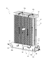
- FIG. 1 is a perspective view of a heat exchanger according to Embodiment 1;
- FIG. 3 is a diagram conceptually showing a cross section along the tube axis direction of a first header and a second header that constitute the heat exchanger according to Embodiment 1;
- FIG. 5 is a diagram conceptually showing a cross section along the pipe axis direction of a first header and a second header of a modification that constitute the heat exchanger according to Embodiment 1;
- 3 is an enlarged perspective view of a first header in part A of FIG. 2;
- FIG. 4 is an exploded perspective view of the first header according to Embodiment 1;
- FIG. 4 is a cross-sectional view along the tube axis direction of the first header, and is a partial cross-sectional view conceptually showing the cross section of the first header at the B portion of FIG. 3 ;
- FIG. 8 is a cross-sectional view conceptually showing a cross section of the first header taken along line CC of FIG. 7;
- 4 is a side view conceptually showing the relationship between the partition plate and the main body of the heat exchanger according to Embodiment 1.
- FIG. FIG. 11 is an enlarged perspective view of part of a first header according to Embodiment 2;
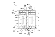
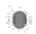
- FIG. 10 is a sectional view conceptually showing a section perpendicular to the tube axis direction of the first header, which is a section of a portion of the first header having the partition plate according to the second embodiment;
- FIG. 8 is a side view conceptually showing the relationship between the partition plate and the main body of the heat exchanger according to Embodiment 2;
- FIG. 11 is an enlarged perspective view of a partition plate used in a first header according to Embodiment 3;
- FIG. 11 is an exploded perspective view of a first header according to Embodiment 4;
- FIG. 11 is an enlarged perspective view showing a part of a first header according to Embodiment 5;
- FIG. 11 is a cross-sectional view along the tube axis direction of a first header according to Embodiment 5, and is a partial cross-sectional view conceptually showing a cross section of a portion where a partition plate is arranged.
- FIG. 1 is a refrigerant circuit diagram of an air conditioner 100 including a heat exchanger 30 according to Embodiment 1.
- FIG. The solid line arrows in FIG. 1 indicate the refrigerant flow during the cooling operation, and the broken line arrows in FIG. 1 indicate the refrigerant flow during the heating operation.
- the heat exchanger 30 is mounted on the outdoor unit 15 of the air conditioner 100 including the outdoor unit 15 and the indoor unit 20 .
- the outdoor unit 15 includes a heat exchanger 30 , a compressor 11 , a flow path switching device 12 and a fan 13 .
- the indoor unit 20 includes an expansion device 21 , an indoor heat exchanger 22 and an indoor fan 23 .
- the air conditioner 100 includes a refrigerant circuit in which the compressor 11, the flow path switching device 12, the heat exchanger 30, the expansion device 21, and the indoor heat exchanger 22 are connected by refrigerant piping and the refrigerant circulates.
- This air conditioner 100 can be operated in both cooling operation and heating operation by switching the channel switching device 12 .
- the compressor 11 sucks in a low-temperature, low-pressure refrigerant, compresses the sucked-in refrigerant, and discharges a high-temperature, high-pressure refrigerant.
- the compressor 11 is, for example, an inverter compressor or the like whose capacity, which is the output amount per unit time, is controlled by changing the operating frequency.
- the channel switching device 12 is, for example, a four-way valve, and switches between cooling operation and heating operation by switching the direction of refrigerant flow.
- the flow switching device 12 switches to the state indicated by the solid line in FIG. 1 during cooling operation, and the discharge side of the compressor 11 and the heat exchanger 30 are connected. Further, the flow path switching device 12 switches to the state indicated by the dashed line in FIG. 1 during the heating operation, and the discharge side of the compressor 11 and the indoor heat exchanger 22 are connected.
- the heat exchanger 30 exchanges heat between the outdoor air and the refrigerant flowing inside the heat exchanger 30 .
- the heat exchanger 30 functions as a condenser that radiates the heat of the refrigerant to the outdoor air to condense the refrigerant during the cooling operation.
- the heat exchanger 30 functions as an evaporator that evaporates the refrigerant during the heating operation and cools the outdoor air with the heat of vaporization at that time.
- the fan 13 supplies outdoor air to the heat exchanger 30, and the amount of air blown to the heat exchanger 30 is adjusted by controlling the rotation speed.
- the throttle device 21 is, for example, an electronic expansion valve that can adjust the opening of the throttle, and controls the pressure of the refrigerant flowing into the heat exchanger 30 or the indoor heat exchanger 22 by adjusting the opening.
- the expansion device 21 is provided in the indoor unit 20 in the embodiment, it may be provided in the outdoor unit 15, and the installation location is not limited.
- the indoor heat exchanger 22 exchanges heat between the indoor air and the refrigerant flowing inside the indoor heat exchanger 22 .
- the indoor heat exchanger 22 functions as an evaporator that evaporates the refrigerant and cools the outdoor air with the heat of vaporization during the cooling operation.
- the indoor heat exchanger 22 functions as a condenser that radiates the heat of the refrigerant to the outdoor air to condense the refrigerant during the heating operation.
- the indoor fan 23 supplies indoor air to the indoor heat exchanger 22, and the amount of air blown to the indoor heat exchanger 22 is adjusted by controlling the rotation speed.
- the liquid refrigerant flows into the expansion device 21, is decompressed and expanded, and becomes a low-temperature, low-pressure gas-liquid two-phase refrigerant.
- the gas-liquid two-phase refrigerant flows into the indoor heat exchanger 22 acting as an evaporator.
- the refrigerant that has flowed into the indoor heat exchanger 22 exchanges heat with the indoor air sent by the indoor fan 23 to evaporate and gasify. At that time, the room air is cooled to cool the room. Thereafter, the vaporized low-temperature, low-pressure gaseous refrigerant passes through the flow path switching device 12 and is sucked into the compressor 11 .
- the heating operation will be explained.
- the refrigerant sucked into the compressor 11 is compressed by the compressor 11 and discharged in a high-temperature and high-pressure gas state.
- the high-temperature and high-pressure gaseous refrigerant discharged from the compressor 11 passes through the flow path switching device 12 and flows into the indoor heat exchanger 22 acting as a condenser.
- the refrigerant that has flowed into the indoor heat exchanger 22 exchanges heat with indoor air sent by the indoor fan 23, condenses, and liquefies. At that time, the room air is warmed, and the room is heated.
- the liquid refrigerant flows into the expansion device 21, is decompressed and expanded, and becomes a low-temperature, low-pressure gas-liquid two-phase refrigerant.
- the gas-liquid two-phase refrigerant flows into the heat exchanger 30 acting as an evaporator.
- the refrigerant that has flowed into the heat exchanger 30 exchanges heat with the outdoor air sent by the fan 13 to evaporate and gasify. Thereafter, the vaporized low-temperature, low-pressure gaseous refrigerant passes through the flow path switching device 12 and is sucked into the compressor 11 .
- FIG. 2 is a perspective view of the heat exchanger 30 according to Embodiment 1.
- FIG. FIG. 3 is a diagram conceptually showing a cross section along the tube axis direction of the first header 34 and the second header 35 that constitute the heat exchanger 30 according to the first embodiment.
- the white arrows in FIG. 2 indicate the flow of air generated by the fan 13.
- FIG. 2 and 3 indicate the flow of refrigerant flowing through the first header 34
- the broken arrows indicate the flow of refrigerant flowing through the second header 35.
- FIG. 2 and 3 indicate the flow of refrigerant flowing through the first header 34
- the broken arrows indicate the flow of refrigerant flowing through the second header 35.
- the heat exchanger 30 has a plurality of heat exchange elements arranged side by side along the air flow direction. Specifically, the heat exchanger 30 has a first heat exchange element 31 on the windward side and a second heat exchange element 32 on the leeward side. The heat exchanger 30 also has a first header 34 , a second header 35 , and a parallel header 42 that are connected to the first heat exchange element 31 and the second heat exchange element 32 .
- the first heat exchange body 31 and the second heat exchange body 32 each have a plurality of heat transfer tubes 38 and a plurality of fins 39 .
- the heat transfer tube 38 is, for example, a flat tube, and has a plurality of flow paths (not shown) through which a refrigerant flows.
- the heat transfer tubes 38 extend vertically.
- the refrigerant flows in the vertical direction inside the tube extending in the vertical direction.
- the up-down direction is, for example, the vertical direction, but it may be a direction inclined with respect to the vertical direction.
- the heat transfer tubes 38 may extend in directions other than the vertical direction.
- the heat transfer tubes 38 are arranged horizontally side by side with a space therebetween so that the wind generated by the fan 13 flows. Fins 39 are arranged between adjacent heat transfer tubes 38 .
- the fins 39 are heat transfer promoting members and are arranged between adjacent heat transfer tubes 38 among the plurality of heat transfer tubes 38 .
- the fins 39 are connected between adjacent heat transfer tubes 38 to transfer heat to the heat transfer tubes 38 .
- the fins 39 improve heat exchange efficiency between air and refrigerant, and corrugated fins are used, for example.
- the fins 39 are not limited to corrugated fins, and may be other heat transfer promoting members such as plate fins.
- the first heat exchanging body 31 and the second heat exchanging body 32 do not need to have the fins 39 because heat exchange between the air and the refrigerant takes place on the surfaces of the heat transfer tubes 38 .
- a first header 34 is connected to the lower end of the first heat exchange body 31 .
- the lower ends of the heat transfer tubes 38 of the first heat exchange body 31 are directly inserted into the first header 34 .
- a plurality of heat transfer tubes 38 are connected to the first header 34 so as to extend upward in the vertical direction.
- the first header 34 is arranged on the windward side with respect to the second header 35 in the flow direction of the air sent by the fan 13, as indicated by the white arrow in FIG.
- the first header 34 functions as a distribution mechanism that distributes the refrigerant flowing into the first heat exchange body 31 to the plurality of heat transfer tubes 38 . Further, the first header 34 functions as a confluence mechanism for merging the refrigerant flowing out from the plurality of heat transfer tubes 38 when the refrigerant flows out from the first heat exchange body 31 .
- the first header 34 is a long tubular member with both ends closed, and a space is formed inside.
- the first header 34 has a main body portion 34a, an end plate 50A, an inlet pipe 61 and an outlet pipe 63, and a partition plate 50, as shown in FIGS.
- the body portion 34a is a member formed in an elongated cylindrical shape, and has a space inside which a coolant flows.
- the body portion 34a is formed in an elliptical shape in a cross section perpendicular to the pipe axis direction of the body portion 34a.
- the main body portion 34a may be formed in a cylindrical shape, and the main body portion 34a may be formed in another shape such as a perfect circle or a polygonal shape in a cross section perpendicular to the pipe axis direction of the main body portion 34a. good too.
- End plates 50A for sealing the refrigerant are arranged at both ends of the body portion 34a.
- the first header 34 is formed in a columnar shape by combining the body portion 34a and the end plate 50A.
- the first header 34 is installed so that the central axis of the longitudinal direction extends horizontally, but the first header 34 may be installed with the central axis of the longitudinal direction inclined with respect to the horizontal direction. .
- the end plate 50A closes the openings at both ends of the main body 34a formed in a cylindrical shape.
- An inlet pipe 61 is connected to an end plate 50A forming one end of the first header 34 in the longitudinal direction of the first header 34 .
- An end plate 50A forming one end of the first header 34 is formed with an inlet opening 62 into which an inlet pipe 61 is inserted.
- the inlet opening 62 is a through hole formed in the end plate 50A.
- An outlet pipe 63 is connected to an end plate 50A forming the other end of the first header 34 in the longitudinal direction of the first header 34 .
- An end plate 50A forming the other end of the first header 34 is formed with an outlet opening 64 into which the outlet pipe 63 is inserted.
- the outlet opening 64 is a through hole formed in the end plate 50A.
- the inlet pipe 61 is an inlet through which the refrigerant flows into the first header 34 .
- the outlet pipe 63 is an outlet through which the refrigerant flows out from the first header 34 .
- the inlet pipe 61 is inserted into the inlet opening 62 and passes through the end plate 50A.
- the outlet pipe 63 is inserted into the outlet opening 64 and passes through the end plate 50A.
- the first header 34 is connected to the refrigerant circuit of the air conditioner 100 via the inlet pipe 61 .
- the first header 34 is connected to the refrigerant circuit of the air conditioner 100 via an outlet pipe 63 .
- the first header 34 forms an internal space 40 separated from the external space of the first header 34 by a main body portion 34a formed in a cylindrical shape and end plates 50A closing both ends of the main body portion 34a.
- the internal space 40 is a space that communicates with the tube inner space of the heat transfer tube 38 and with the tube inner spaces of the inlet pipe 61 and the outlet pipe 63 .
- a partition plate 50 is provided in the internal space 40 of the first header 34 .
- the partition plate 50 is a plate-like member.
- the partition plate 50 constitutes a wall that divides the internal space 40 of the first header 34 into a plurality of spaces in the direction parallel to the pipe axis direction of the first header 34 .
- the partition plate 50 divides the internal space 40 in a direction parallel to the pipe axis direction of the first header 34 to form a plurality of spaces inside the first header 34 .
- a distribution space 41 and a confluence space 43 are formed inside the first header 34 by a partition plate 50 .
- the distribution space 41 is a space in the first header 34 in which the refrigerant distributed to the plurality of heat transfer tubes 38 exists.
- the confluence space 43 is a space in the first header 34 where the refrigerants flowing out from the plurality of heat transfer tubes 38 merge. Since the distribution space 41 and the merging space 43 are separated by the partition plate 50 , the refrigerant does not move between the distribution space 41 and the merging space 43 . That is, in the internal space 40 of the first header 34 , the adjacent spaces separated by the partition plate 50 do not communicate with each other, and the coolant does not move between the adjacent spaces separated by the partition plate 50 .
- the first header 34 has at least one or more partition plates 50 .
- FIG. 4 is a diagram conceptually showing a cross-section along the pipe axis direction of a first header 34 and a second header 35 of a modification that constitute the heat exchanger 30 according to Embodiment 1.
- the first header 34 when it has a plurality of partition plates 50 , it may have a confluence/distribution space 45 functioning as a distribution space 41 and a confluence space 43 .
- the confluence/distribution space 45 is a space where the refrigerant flowing out from the plurality of heat transfer tubes 38 merges, and is a space in which the merged refrigerant is distributed to the other plurality of heat transfer tubes 38 again.
- the merging/distributing space 45 is formed between the merging space 43 and the distributing space 41 in a direction parallel to the tube axis direction of the first header 34 .
- a second header 35 is connected to the lower end of the second heat exchange body 32 .
- the lower ends of the heat transfer tubes 38 of the second heat exchange body 32 are directly inserted into the second header 35 .
- a plurality of heat transfer tubes 38 are connected to the second header 35 so as to extend upward in the vertical direction.
- the second header 35 is arranged in parallel with the first header 34 .
- the second header 35 is arranged on the leeward side with respect to the first header 34 in the direction in which the air sent by the fan 13 flows, as indicated by the white arrow in FIG.
- the second header 35 and the first header 34 are arranged at the same height with respect to the ground and arranged parallel to each other.
- the second header 35 functions as a confluence mechanism for merging the refrigerant flowing from the plurality of heat transfer tubes 38 when the refrigerant flows from the first heat exchange body 31 .
- the second header 35 also functions as a distribution mechanism that distributes the refrigerant flowing out from the second heat exchange body 32 to the first heat exchange body 31 to the heat transfer tubes 38 .
- the second header 35 is a member formed in a long tubular shape with both ends closed, and a space is formed inside.
- the second header 35 as shown in FIGS. 2 and 3, has a body portion 34a and an end plate 50A.
- the body part 34a is a member formed in an elongated cylindrical shape, and has a space formed therein.
- the body portion 34a is formed in an elliptical shape in a cross section perpendicular to the pipe axis direction of the body portion 34a.
- the main body portion 34a may be formed in a cylindrical shape, and the main body portion 34a may be formed in another shape such as a perfect circle or a polygonal shape in a cross section perpendicular to the pipe axis direction of the main body portion 34a. good too.
- End plates 50A for sealing the refrigerant are arranged at both ends of the body portion 34a.
- the second header 35 is formed in a columnar shape by combining the body portion 34a and the end plate 50A.
- the second header 35 is installed so that the central axis of the longitudinal direction extends horizontally, but the second header 35 may be installed with the central axis of the longitudinal direction inclined with respect to the horizontal direction. .
- the end plate 50A closes the openings at both ends of the main body 34a formed in a cylindrical shape.
- the second header 35 forms an internal space 40 separated from the external space of the second header 35 by a body portion 34a formed in a cylindrical shape and end plates 50A closing both ends of the body portion 34a. .
- the internal space 40 of the second header 35 communicates with the internal space of the heat transfer tube 38 .
- the internal space 40 of the second header 35 is a space where the refrigerant flowing out from the multiple heat transfer tubes 38 merges, and the merged refrigerant is distributed to the other multiple heat transfer tubes 38 again.
- Refrigerant flows into the internal space 40 of the second header 35 from the internal space 40 of the first header 34 via a plurality of heat transfer tubes 38 .
- the refrigerant flows from the internal space 40 of the second header 35 into the internal space 40 of the first header 34 via the plurality of heat transfer tubes 38 .
- the partition plate 50 is not provided in the second header 35.
- the second header 35 may have a partition plate 50 .
- the partition plate 50 divides the inner space 40 of the second header 35 into a plurality of spaces in the direction parallel to the tube axis direction of the second header 35 . construct a wall.
- the second header 35 may be divided by partition plates 50 so that the internal space 40 forms a plurality of rooms. The detailed structure of the first header 34 and the second header 35 will be described later.
- the row-connecting header 42 is provided at the end of the plurality of heat transfer tubes 38 on the side opposite to the connection side of the two headers.
- the row-to-row header 42 includes a plurality of heat transfer tubes 38 connected to one of the two headers of the first header 34 and the second header 35, and Refrigerant is circulated between the plurality of heat transfer tubes 38 connected to the other header.
- the row-connecting header 42 is provided facing the first header 34 and the second header 35 with the heat transfer tubes 38 interposed therebetween.
- the row-to-row header 42 is provided at the upper end portion of the first heat exchanging body 31 and the second heat exchanging body 32 .
- the upper end of the heat transfer tube 38 is inserted.
- a plurality of heat transfer tubes 38 connected to the first header 34 and the second header 35 are connected to row-to-row headers 42 positioned above the first header 34 and the second header 35 .
- the parallel header 42 includes a plurality of heat transfer tubes 38 having one end communicating with the distribution space 41 of the first header 34 , and a plurality of heat transfer tubes 38 having one end communicating with the internal space 40 of the second header 35 .
- a first flow path 42a is formed to communicate with the end.
- the plurality of heat transfer tubes 38 communicating with the distribution space 41 of the first header 34 are included in the first heat exchange body 31, and the plurality of heat transfer tubes 38 communicating with the internal space 40 of the second header 35 are It is included in the second heat exchange body 32 .
- the number of first flow paths 42a formed may be one or plural.
- the parallel header 42 has a plurality of heat transfer tubes 38 whose one end communicates with the internal space 40 of the second header 35 , and a plurality of heat transfer tubes 38 whose one end communicates with the merge space 43 of the first header 34 .
- a second flow path 42b is formed to communicate with the other end of the .
- the plurality of heat transfer tubes 38 communicating with the confluence space 43 of the first header 34 are included in the first heat exchange body 31, and the plurality of heat transfer tubes 38 communicating with the internal space 40 of the second header 35 are It is included in the second heat exchange body 32 .
- the number of second flow paths 42b formed may be one or plural.
- the parallel header 42 distributes the refrigerant flowing through the first heat exchange element 31 to the second heat exchange element 32 facing in the lateral direction, and distributes the refrigerant flowing through the second heat exchange element 32 in the lateral direction. It is made to flow through the opposing first heat exchange bodies 31 .
- the row-connecting header 42 forms a flow path so as to communicate the respective heat transfer tubes 38 arranged facing each other in the width direction.
- the plurality of heat transfer tubes 38, fins 39, first header 34, second header 35, parallel header 42, inlet pipe 61, and outlet pipe 63 are all made of aluminum and joined by brazing.
- the header base 9, header cover 10, and partition plate 50 are all made of aluminum and joined by brazing.
- the plurality of heat transfer tubes 38, fins 39, first header 34, second header 35, parallel header 42, inlet pipe 61, and outlet pipe 63 are not limited to being made of aluminum, and may be made of other metals.
- the header base 9, the header cover 10, and the partition plate 50 are not limited to being made of aluminum, and may be made of other metals.
- the refrigerant flows from the outside of the heat exchanger 30 through the inlet pipe 61 into the distribution space 41 that is the internal space 40 of the first header 34 .
- the refrigerant that has flowed into the distribution space 41 flows inside the heat transfer tubes 38 included in the first heat exchange body 31 that communicates with the distribution space 41 , and flows into the first flow paths 42 a of the parallel header 42 .
- the refrigerant that has flowed into the first flow path 42 a flows into the internal space 40 of the second header 35 through the heat transfer tubes 38 of the second heat exchange body 32 communicating with the first flow path 42 a.
- the refrigerant that has flowed into the internal space 40 of the second header 35 flows through the inside of the heat transfer tubes 38 included in the second heat exchanger 32, the other end of which communicates with the second flow path 42b. It flows into channel 42b.
- the refrigerant that has flowed into the second flow path 42b passes through the heat transfer tubes 38 of the first heat exchange body 31 communicating with the second flow path 42b and flows into the confluence space 43 that is the internal space 40 of the first header 34 .
- the refrigerant that has flowed into the confluence space 43 of the first header 34 flows out of the heat exchanger 30 through the outlet pipe 63 .
- the first header 34 is provided with the partition plate 50, the inlet pipe 61 and the outlet pipe 63
- the second header 35 is provided with the partition plate 50 and the inlet pipe.
- a structure without 61 and outlet pipe 63 is shown.
- the heat exchanger 30 is not limited to this structure, and the structure of the first header 34 and the structure of the second header 35 may be exchanged. That is, the heat exchanger 30 may have a structure in which the second header 35 is provided with the partition plate 50, the inlet pipe 61 and the outlet pipe 63, and the first header 34 is not provided with the partition plate 50, the inlet pipe 61 and the outlet pipe 63. .
- first header 34 and the second header 35 has the partition plate 50. As shown in FIG. 4, both the first header 34 and the second header 35 may have a partition plate 50 .
- the inlet pipe 61 and the outlet pipe 63 may be provided in separate headers.
- the inlet piping 61 may be provided in the first header 34 and the outlet piping 63 may be provided in the second header 35 .
- FIG. 5 is an enlarged perspective view of the first header 34 in section A of FIG.
- FIG. 6 is an exploded perspective view of the first header 34 according to Embodiment 1.
- FIG. FIG. 7 is a cross-sectional view of the first header 34 along the pipe axis direction, and is a partial cross-sectional view conceptually showing the cross section of the first header 34 at the portion B in FIG.
- FIG. 8 is a cross-sectional view conceptually showing a cross-section of the first header 34 taken along line CC of FIG.
- FIG. 7 shows the position of the connection port 94 of the heat transfer tube 38. As shown in FIG. In addition, in FIG.
- the body portion 34 a of the first header 34 has a header base 9 and a header cover 10 .
- the header base 9 and the header cover 10 are arranged so as to face each other in the direction in which the heat transfer tubes 38 extend.
- a body portion 34a of the first header 34 is formed in a cylindrical shape by combining the header base 9 and the header cover 10 together.
- the body portion 34a is formed in a tubular shape by combining the header base 9 and the header cover 10, and both longitudinal ends of the tubular header base 9 and the header cover 10 are end plates. It is blocked by 50A.
- the body portion 34a is formed in a columnar shape by combining the header base 9, the header cover 10, and the end plate 50A.
- the header base 9 is an elongated member, and has a U-shaped cross section perpendicular to the pipe axis direction of the first header 34, which is the longitudinal direction.
- the header base 9 is formed such that the U-shaped portion is continuous in the longitudinal direction.
- the U-shaped inner wall surface is defined as a base inner wall surface 9 a of the header base 9
- the U-shaped outer wall surface is defined as a base outer wall surface 9 b of the header base 9 . That is, in the header base 9, the base inner wall surface 9a and the base outer wall surface 9b form surfaces opposite to each other.
- the header base 9 is formed so as to bridge between a pair of base side portions 93 forming plate surfaces facing each other and end portions of the pair of base side portions 93 , and is connected to the plurality of heat transfer tubes 38 . It has a top surface portion 91 that As shown in FIG. 6, in the header base 9, the top surface portion 91 forms a curved portion, and the base side surface portion 93 forms a flat portion.
- the top surface portion 91 is a portion formed in an arc shape
- the base side surface portion 93 is a portion formed in a straight line shape. .
- the top surface portion 91 bridges the upper end portions of the two base side surface portions 93 and is curved so as to protrude outward from the main body portion 34a.
- the top surface portion 91 is curved so as to protrude toward the row-connecting header 42 arrangement side.
- the header base 9 has a top surface portion 91 so that at least a portion of the header base 9 is curved so as to protrude on the side opposite to the header cover 10 .
- the top surface portion 91 is not limited to a structure that is curved so as to protrude outward from the main body portion 34a, and the top surface portion 91 may be formed in a flat plate shape.
- the two base side surface portions 93 are formed such that the base inner wall surfaces 9a are opposed to each other, and extend substantially parallel to the tube axis direction.
- the top surface portion 91 and the two base side portions 93 are integrally formed.
- base side surface portions 93 are provided at both end portions of an arc-shaped top surface portion 91 .
- the base inner wall surfaces 9a of the two base side portions 93 face and abut on the cover outer wall surface 10b of the cover side portion 103 of the header cover 10, which will be described later.
- Each of the two base side portions 93 is joined to each of the cover side portions 103 of the header cover 10 .
- a connection port 94 into which the heat transfer tube 38 is inserted is formed in the top surface portion 91 of the header base 9 .
- the connection ports 94 are through holes and are formed in plurality along the longitudinal direction of the header base 9 .
- a plurality of connection ports 94 into which the plurality of heat transfer tubes 38 are respectively inserted are formed in the body portion 34a at intervals in the tube axis direction.
- a distance W1 (see FIG. 6) between adjacent connection ports 94 among the plurality of connection ports 94 is four times or less the plate thickness W2 of the header base 9 .
- the heat transfer tubes 38 are inserted into the connection ports 94 and pass through the top surface portion 91 of the header base 9 .
- the heat transfer tubes 38 inserted into the connection ports 94 are joined to the header base 9 and held by the header base 9 .
- the opening formed by the base distal end portions 9c of the two base side surface portions 93 is referred to as the base opening portion 9d.
- the base front end portion 9 c is an end portion of the base side surface portion 93 located on the opposite side of the top surface portion 91 .
- Each of the pair of base side surface portions 93 is formed in a plate shape and has a base cutout portion 92 forming a hole extending from the opposite end of the top surface portion 91 toward the top surface portion 91 side.
- the base cutout portion 92 is formed to extend from the base tip portion 9c toward the top surface portion 91 .
- the base cut portion 92 forms a hole penetrating the base side surface portion 93 .
- the header base 9 has base cutouts 92 at the ends opposite to the top surface 91 on each of the two base side surfaces 93 .
- the header base 9 has base cutouts 92 forming through holes on both side surfaces.
- the header cover 10 is combined with the header base 9 to form an internal space 40 of the first header 34 together with the header base 9 .
- the header cover 10 is an elongated member, and has a U-shaped cross section perpendicular to the pipe axis direction of the first header 34, which is the longitudinal direction.
- the header cover 10 is formed in a shape in which the U-shaped portion is continuous in the longitudinal direction.
- the U-shaped inner wall surface is defined as a cover inner wall surface 10 a of the header cover 10
- the U-shaped outer wall surface is defined as a cover outer wall surface 10 b of the header cover 10 . That is, in the header cover 10, the cover inner wall surface 10a and the cover outer wall surface 10b form surfaces opposite to each other.
- the header cover 10 is formed so as to bridge between a pair of cover side portions 103 forming plate surfaces facing each other and end portions of the pair of cover side portions 103. It has the bottom part 101 which opposes. In the header cover 10, the bottom portion 101 forms a curved portion, and the cover side portion 103 forms a flat portion. In the U-shaped first header 34 in a vertical cross section with respect to the pipe axis direction, the bottom surface portion 101 is an arcuate portion, and the cover side surface portion 103 is a straight portion. .
- the bottom surface portion 101 bridges the lower end portions of the two cover side surface portions 103 and is curved so as to protrude outward from the main body portion 34a.
- the bottom portion 101 is curved so as to protrude toward the side opposite to the side where the row-connecting headers 42 are arranged.
- the header cover 10 has a bottom portion 101 so that at least a portion of the header cover 10 is curved so as to protrude on the side opposite to the header base 9 . It should be noted that the bottom surface portion 101 is not limited to a curved structure that protrudes outward from the main body portion 34a, and the bottom surface portion 101 may be formed in a flat plate shape.
- the two cover side surfaces 103 are formed so that the inner wall surfaces 10a of the covers face each other, and extend substantially parallel to the pipe axis direction.
- the bottom portion 101 and the two cover side portions 103 are integrally formed.
- cover side portions 103 are provided at both ends of a bottom portion 101 formed in an arc shape.
- the cover outer wall surfaces 10b of the two cover side portions 103 face and abut against the base inner wall surface 9a of the base side portion 93 of the header base 9 .
- Each of the two cover side portions 103 is joined to each of the base side portions 93 of the header base 9 .
- the opening formed by the cover tip portions 10c of the two cover side portions 103 is referred to as a cover opening 10d.
- the cover front end portion 10 c is an end portion of the cover side portion 103 located on the opposite side of the bottom portion 101 .
- Each of the pair of cover side surface portions 103 is formed in a plate shape and has a cover cutout portion 102 forming a hole extending from the opposite end of the bottom surface portion 101 toward the bottom surface portion 101 side.
- Cover cut portion 102 is formed to extend from cover tip portion 10 c toward bottom portion 101 .
- Cover cutout 102 forms a hole penetrating through cover side surface 103 .
- the header cover 10 has cover cutouts 102 at the ends opposite to the bottom surface 101 in each of the two cover side surfaces 103 .
- the header cover 10 has cover cutouts 102 forming through holes on both side surfaces.
- the header base 9 and the header cover 10 are combined with each other so that the base opening 9d and the cover opening 10d face each other.
- the header cover 10 is inserted into the base opening 9d of the header base 9 while the header base 9 and the header cover 10 are combined.
- the distance L1 between the base inner wall surfaces 9a of the two opposing base side portions 93 is the distance between the cover inner wall surfaces 10a of the two opposing cover side portions 103. Larger than L2.
- the base inner wall surface 9a of the top surface portion 91 and the cover inner wall surface 10a of the bottom surface portion 101 face each other when the header base 9 and the header cover 10 are combined. Further, in a state in which the header base 9 and the header cover 10 are combined, the base side portion 93 and the cover side portion 103 face each other and abut each other. In this state, the base inner wall surface 9a of the base side surface portion 93 and the cover outer wall surface 10b of the cover side surface portion 103 face each other and abut each other. That is, in the main body portion 34a, the base inner wall surfaces 9a of the pair of base side portions 93 and the cover outer wall surfaces 10b of the pair of cover side portions 103 are in contact with each other.
- the insertion portion 34b is formed by overlapping a base cutout portion 92 and a cover cutout portion 102 from the inner side to the outer side of the main body portion 34a.
- the insertion portion 34b of the body portion 34a is a through hole formed in the body portion 34a.
- a side plate portion 52 of the partition plate 50 to be described later is inserted into the insertion portion 34 b , and the insertion portion 34 b engages with the partition plate 50 .
- the body portion 34a has a pair of insertion portions 34b that form through holes and are engaged with the partition plate 50 in the wall portions facing each other on both side surfaces of the body portion 34a.
- the partition plate 50 has a wall portion 51 and side plate portions 52, as shown in FIGS.
- the wall portion 51 is a plate-like member, and is a portion of the partition plate 50 that constitutes a wall that mainly divides the internal space 40 of the main body portion 34a in the pipe axis direction.
- the wall portion 51 is formed in the same shape as the internal space 40 when viewed in a direction parallel to the pipe axis direction of the first header 34 . That is, when viewed in a direction parallel to the pipe axis direction of the first header 34, the outer edge portion 51a of the wall portion 51 is formed in a shape along the inner wall 34c of the main body portion 34a.
- the outer edge portion 51a of the wall portion 51 is in contact with the inner wall 34c of the main body portion 34a.
- the inner wall 34c of the main body portion 34a with which the partition plate 50 abuts is formed by the base inner wall surface 9a of the header base 9 and the cover inner wall surface 10a of the header cover 10. contains.
- the side plate portion 52 is a portion protruding from the wall portion 51 and a portion protruding from the outer edge portion 51 a of the wall portion 51 .
- the partition plate 50 has a pair of side plate portions 52 projecting from both side surfaces of the wall portion 51 .
- the pair of side plate portions 52 each protrude from the wall portion 51 in a direction perpendicular to the tube axis direction of the first header 34 .
- the side plate portion 52 is inserted into the insertion portion 34b of the main body portion 34a of the partition plate 50 .
- the side plate portion 52 is inserted into the insertion portion 34b of the main body portion 34a and used for temporarily fixing the partition plate 50 and the main body portion 34a.
- Each of the pair of side plate portions 52 is a distal end portion of the pair of side plate portions 52 in the projecting direction, and when inserted into the pair of insertion portions 34b, the through holes formed by the insertion portions 34b are inserted into the through holes. It has a plate tip portion 53 that closes off.
- the plate tip portion 53 is formed so as to extend along the shape of the hole of the insertion portion 34b when inserted into the insertion portion 34b.
- the plate tip portion 53 forms a tip wall in the projecting direction of the side plate portion 52 and includes the tip surface of the side plate portion 52 .
- the plate tip portion 53 forms part of the outer wall surface of the main body portion 34a when the side plate portion 52 is inserted into the insertion portion 34b.
- the plate tip portion 53 is used to block at least a portion of the base cut portion 92 formed in the header base 9. be done.
- the plate tip portion 53 does not protrude outside the main body portion 34a from each of the pair of insertion portions 34b when the main body portion 34a and the partition plate 50 are combined.
- the wall of the plate tip portion 53 is deformed into a state in which the wall of the plate tip portion 53 is expanded in a direction parallel to the tube axis direction of the first header 34 so that the end face forms a V-shaped groove. . Since the plate tip portion 53 is deformed in a state of being pushed and spread in the direction parallel to the tube axis direction, the pair of insertion portions 34b is pushed inside the through hole formed by each of the pair of insertion portions 34b. is engaged with the inner wall 34b1 of the
- the plate tip portion 53 is pressed and deformed using an instrument in the insertion portion 34b, so that the tip surface of the plate tip portion 53 is expanded, and the side plate portion 52 of the partition plate 50 and the insertion portion 34b are separated. is in close contact.
- the inner wall 34b1 is pushed wide so that the size of the opening of the insertion portion 34b becomes larger, and the outer edge portion 53b of the deformed plate front end portion 53 and the insertion portion 34b are expanded. may be fitted with the inner wall 34b1.
- the plate leading end portion 53 that is pushed out is in close contact with the base cut portion 92 of the header base 9 , and locks the partition plate 50 and the header base 9 .
- the plate tip portion 53 of the partition plate 50 is pushed and spread with respect to the base portion serving as the root portion of the side plate portion 52. is formed in Since the plate tip portion 53 is formed in an expanded state inside the insertion portion 34b, the outer edge portion 53b of the plate tip portion 53 is in close contact with the inner wall 34b1 inside the insertion portion 34b, and the side plate portion 52 is It is fixed to the inner wall 34b1 of the insertion portion 34b.
- the plate tip portion 53 is pressed and deformed by using, for example, a V-shaped die in the insertion portion 34b, so that the tip surface of the plate tip portion 53 is split left and right.
- the plate front end portion 53 pushed and spread left and right comes into close contact with the inner wall 34b1 of the insertion portion 34b.
- the left and right referred to here are directions parallel to the pipe axis direction of the first header 34 .
- a groove portion 53a recessed toward the wall portion 51 is formed.
- the groove portion 53 a is formed so as to extend in a direction perpendicular to the pipe axis direction of the first header 34 .
- the direction in which the grooves 53 a extend is parallel to the direction in which the heat transfer tubes 38 extend in the first header 34 .
- the partition plate 50 is temporarily fixed to the header base 9 by expanding the front end surface of the plate front end portion 53 into, for example, a V-shape, and by bringing the side plate portion 52 into close contact with the insertion portion 34b.
- the plate tip portion 53 is deformed into a V shape when the plate tip portion 53 is deformed.
- the plate tip end portion 53 inserted into the insertion portion 34b may be formed in a state in which only a portion of the insertion portion 34b is expanded in the direction perpendicular to the pipe axis direction of the first header 34. Better, all the parts in the insertion part 34b may be formed in a state of being pushed and spread.
- the deformed portion of the plate tip portion 53 is the entire side surface of the partition plate 50, but if the partition plate 50 and the header base 9 of the main body portion 34a are temporarily fixed, the plate tip portion 53 may be deformed.
- the portion 53 may be partially deformed in the longitudinal direction of the side plate portion 52 .
- the groove portion 53a is perpendicular to the pipe axis direction of the first header 34. In the direction, it may be formed only on a portion of the plate tip 53 that is within the insertion portion 34b. Alternatively, the groove portion 53a may be formed in the entire portion of the plate tip portion 53 within the insertion portion 34b in the direction perpendicular to the pipe axis direction of the first header 34. As shown in FIG.
- the end plate 50A may have the structure of the partition plate 50 described above.
- the structure of the first header 34 described above is intended to temporarily fix the body portion 34a and the partition plate 50, but may be used for temporarily fixing the body portion 34a and the end plate 50A.
- the relationship between the body portion 34a and the partition plate 50 has been described as the structure of the first header 34, when the second header 35 has the partition plate 50, the relationship between the body portion 34a and the partition plate 50 described above is as follows. It can be applied to the relationship between the main body portion 34 a of the second header 35 and the partition plate 50 .
- the header cover 10 was placed inside the header base 9, but the header cover 10 may be placed outside the header base 9. In this case, the base outer wall surface 9b of the header base 9 and the cover inner wall surface 10a of the header cover 10 abut on the main body portion 34a. The plate leading end portion 53 that has been pushed out is brought into close contact with the cover cutout portion 102 of the header cover 10 to lock the partition plate 50 and the header cover 10 together.
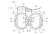
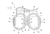
- FIG. 9 is a side view conceptually showing the relationship between the partition plate 50 and the main body portion 34a of the heat exchanger 30 according to the first embodiment. 9 shows the heat exchanger 30 in which the partition plate 50 is also used for the second header 35. As shown in FIG. White arrows in FIG. 9 indicate the flow of air generated by the fan 13 .
- the plate tip end portion 53 does not protrude outside the main body portion 34a from each of the pair of insertion portions 34b when the main body portion 34a and the partition plate 50 are combined. Further, the plate tip portion 53 is deformed into a state in which the wall of the plate tip portion 53 is expanded in the direction parallel to the pipe axial direction so that the end face forms a V-shaped groove, and the pair of insertion Inside the through hole formed by each of the portions 34b, the inner walls 34b1 of the pair of insertion portions 34b are engaged. Therefore, the heat exchanger 30 does not need to fix the main body portion 34 a and the partition plate 50 by projecting the partition plate 50 from the outer side surface of the first header 34 .
- the heat exchanger 30 is compared with a header that requires the partition plate 50 to protrude outside the main body portion 34a in order to fix the main body portion 34a and the partition plate 50.
- the width of the first header 34 can be reduced even if the partition plate 50 is provided inside the header 34 .
- the width of the first header 34 is the length of the first header 34 in the direction of air flow through the heat exchanger 30 .
- the heat exchanger 30 can reduce the width of the second header 35 even if the partition plate 50 is provided inside the second header 35 .
- the width of the heat exchanger 30 can be reduced, and the installation space of the heat exchanger 30 can be reduced. can do.
- the plate tip portion 53 is deformed into a state in which the wall of the plate tip portion 53 is expanded in the direction parallel to the pipe axial direction so that the end face forms a V-shaped groove, and the pair of insertion Inside the through hole formed by each of the portions 34b, the inner walls 34b1 of the pair of insertion portions 34b are engaged. Therefore, in the heat exchanger 30, the gap between the insertion portion 34b and the side plate portion 52 can be reduced, and the airtightness of the first header 34 or the second header 35 can be ensured.
- the plate tip portion 53 is deformed into a spread state, thereby preliminarily closing the gap between the insertion portion 34b and the side plate portion 52.
- the airtightness of the first header 34 or the second header 35 can be ensured without needing to be formed large.
- the heat exchanger 30 is formed by combining the header base 9 and the header cover 10 to form the body portion 34a. Therefore, the partition plate 50 can be arranged between the divided header base 9 and the header cover 10, and the operator can easily attach the partition plate 50 to the main body portion 34a.
- the insertion portion 34b is formed by overlapping the base cutout portion 92 and the cover cutout portion 102 from the inside to the outside of the main body portion 34a. Therefore, by arranging the side plate portion 52 of the partition plate 50 in the base cut portion 92 or the cover cut portion 102, the side plate portion 52 can be inserted into the insertion portion 34b when combining the header base 9 and the header cover 10. can do. Therefore, the operator can easily attach the partition plate 50 to the main body portion 34a.
- the base inner wall surfaces 9a of the pair of base side surfaces 93 and the cover outer wall surfaces 10b of the pair of cover side surfaces 103 are in contact. Therefore, an operator can form the main body portion 34a by combining the header base 9 and the header cover 10, and can easily manufacture the first header 34 or the second header 35.
- the width of the header base 9 or the header cover 10 can be the same as the width of the first header 34 or the second header 35 because the heat exchanger 30 has this configuration.
- the distance between adjacent connection ports 94 among the plurality of connection ports 94 is four times or less the plate thickness of the header base 9 . Therefore, in the heat exchanger 30, the distance between adjacent heat transfer tubes 38 can be reduced compared to a heat exchanger that does not have this configuration, and the number of heat transfer tubes 38 in the tube axis direction of the first header 34 can be reduced to can be increased and the performance of the heat exchanger 30 can be improved.
- FIG. 10 is an enlarged perspective view of part of the first header 34 according to the second embodiment.
- FIG. 11 is a cross-sectional view of a portion of the first header 34 having the partition plate 50 according to Embodiment 2, and conceptually showing a cross section perpendicular to the tube axis direction of the first header 34 .
- members behind the partition plate 50 are indicated by dotted lines.
- Components having the same functions and actions as those of the heat exchanger 30 and the like according to the first embodiment are denoted by the same reference numerals, and descriptions thereof are omitted.
- the second embodiment will be described with a focus on the differences from the first embodiment, and the configurations not described in the second embodiment are the same as those of the first embodiment.
- the structure of the body portion 34a constituting the first header 34 is different from the structure of the body portion 34a of the first header 34 according to the first embodiment.
- the combination of the header base 9 and the header cover 10 is different from that of the main body portion 34a of the first header 34 according to the first embodiment.
- the method of combining the base 9 and the header cover 10 is different.
- one base side surface portion 93 of the pair of base side surface portions 93 is arranged inside the cover opening 10d of the header cover 10 .
- one of the pair of cover side portions 103 is arranged inside the base opening 9 d of the header base 9 .
- the base side portion 93 and the cover side portion 103 face each other and abut each other.
- the inside of one of the pair of base side surfaces 93 is in contact with the outside of one of the cover side surfaces 103, and the outside of the other of the pair of base side surfaces 93 is in contact with the other. contact with the inner side of the cover side portion 103 of the .
- the base inner wall surface 9a of one of the pair of base side surfaces 93 and the cover side surface 103 of the pair of cover side surfaces 103 are mounted. and the outer wall surface 10b of the cover face each other and abut each other.
- the base outer wall surface 9b of the other base side surface portion 93 of the pair of base side surface portions 93 and the other cover side surface of the pair of cover side surface portions 103 are formed.
- the portion 103 and the inner wall surface 10a of the cover face each other and abut each other.
- the body portion 34a abuts against the base inner wall surface 9a of one of the pair of base side surfaces 93 and the cover outer wall surface 10b of one of the pair of cover side surfaces 103. in contact with Further, the main body portion 34a abuts against the base outer wall surface 9b of the other base side surface portion 93 of the pair of base side surface portions 93 and the cover inner wall surface 10a of the other cover side surface portion 103 of the pair of cover side surface portions 103. in contact with
- the widened plate tip portion 53 of the partition plate 50 is attached to the header base. 9 and the partition plate 50 and the header base 9 are locked.
- the spread plate tip portion 53 of the partition plate 50 is It is in close contact with the cover notch 102 of the header cover 10 .
- the partition plate 50 and the header cover 10 are locked by the close contact between the plate tip portion 53 and the cover cutout portion 102 of the header cover 10 .
- the base inner wall surface 9a of one of the pair of base side portions 93 and the cover outer wall surface 10b of one of the pair of cover side portions 103 are in contact with each other.
- the main body portion 34a abuts against the base outer wall surface 9b of the other base side surface portion 93 of the pair of base side surface portions 93 and the cover inner wall surface 10a of the other cover side surface portion 103 of the pair of cover side surface portions 103. in contact with
- the first header 34 according to the second embodiment has this configuration, so that the widened plate tip portion 53 of the partition plate 50 comes into contact with both the header base 9 and the header cover 10 , so that the header The base 9, the header cover 10, and the partition plate 50 are locked. Therefore, in the first header 34 according to the second embodiment, the spread plate tip portion 53 of the partition plate 50 temporarily fixes the three components of the partition plate 50, the header base 9, and the header cover 10 to each other. be able to. Since the three parts of the partition plate 50, the header base 9, and the header cover 10 according to the second embodiment can be temporarily fixed to each other, the two parts of the partition plate 50 and the header base 9, or the partition plate 50 and the header cover 10, the temporary fixation can be strengthened.
- the first header 34 according to the second embodiment is a state in which the header base 9 and the header cover 10 are combined like the first header 34 according to the first embodiment. It is not inserted into the base opening 9d. Therefore, in the first header 34 according to Embodiment 2, the bending shape of the header base 9 and the bending shape of the header cover 10 can be made common, and the header base 9 and the header cover 10 can be the same part.
- the header base 9 and the header cover 10 can be made of the same part, so that the mold for forming the header base 9 and the header cover 10 can be shared. It is possible to suppress the mold manufacturing cost. Moreover, in the first header 34 according to the second embodiment, the header base 9 and the header cover 10 can be made of the same component, and there is no need to manufacture the header base 9 and the header cover 10 separately. The productivity of the exchanger 30 can be improved.
- FIG. 12 is a side view conceptually showing the relationship between the partition plate 50 and the main body portion 34a of the heat exchanger 30 according to the second embodiment. 12 shows the heat exchanger 30 in which the partition plate 50 is also used for the second header 35. As shown in FIG. White arrows in FIG. 12 indicate the flow of air generated by the fan 13 . Since the partition plate 50 does not protrude from the outer side surfaces of the first header 34 and the second header 35 when the partition plate 50 and the main body portion 34a are temporarily fixed, the width of the first header 34 and the second header 35 is reduced. can be shortened. Further, as shown in FIG. 12, by arranging the outer sides of the first header 34 and the second header 35 so as to face each other, the width of the fins 39 is the same as in the first embodiment, The width of the fin 39 is never widened.
- FIG. 13 is an enlarged perspective view of the partition plate 50 used in the first header 34 according to the third embodiment.
- Components having the same functions and actions as the first header 34 and the like according to Embodiments 1 and 2 are denoted by the same reference numerals, and descriptions thereof are omitted.
- the following description focuses on the differences of the third embodiment from the first and second embodiments, and the configurations not described in the third embodiment are the same as those of the first and second embodiments.
- the first header 34 according to Embodiment 3 specifies the shape of the side plate portion 52 of the partition plate 50 .
- a mountain-shaped portion 54 is formed on the side plate portion 52 of the partition plate 50 .
- Each of the pair of side plate portions 52 has a mountain-shaped portion 54 formed in the shape of a triangular prism on the wall facing the inner wall 34b1 of the insertion portion 34b in the direction parallel to the pipe axis direction of the first header 34.
- a plurality of mountain-shaped portions 54 are formed on each of the pair of side plate portions 52 , and the plurality of mountain-shaped portions 54 are formed in parallel in a direction parallel to the direction in which the heat transfer tubes 38 extend.
- the mountain-shaped portion 54 is formed in the shape of a triangular prism.
- the mountain-shaped portion 54 is formed on the plate surface of the side plate portion 52 of the partition plate 50 so that one vertex portion of the mountain-shaped portion 54 formed in the shape of a triangular prism protrudes.
- the mountain-shaped portion 54 is formed so as to extend between the plate tip portion 53 and the base serving as the root portion of the side plate portion 52 .
- the plate surface of the side plate portion 52 on which the mountain-shaped portion 54 is formed is a plate surface perpendicular to the direction parallel to the tube axis direction of the first header 34 . That is, the plate surface of the side plate portion 52 on which the mountain-shaped portion 54 is formed faces in the same direction as the wall portion 51 of the partition plate 50, and in parallel with the pipe axial direction of the first header 34. It's a side that has been.
- the mountain-shaped portions 54 are formed on both sides of the side plate portion 52 in the direction parallel to the tube axis direction of the first header 34 .
- the mountain-shaped portion 54 is formed at a position facing the inner wall 34b1 of the insertion portion 34b of the main body portion 34a. That is, the mountain-shaped portion 54 is formed at a position facing the base cut portion 92 of the header base 9 . Moreover, when the header cover 10 is arranged outside the header base 9 , the mountain-shaped portion 54 may be formed at a position facing the cover cutout portion 102 of the header cover 10 .
- a plurality of mountain-shaped portions 54 are formed on the side plate portion 52 of the partition plate 50 .
- a plurality of mountain-shaped portions 54 are formed side by side in the longitudinal direction of the side plate portion 52 .
- the plurality of mountain-shaped portions 54 are formed side by side in a direction parallel to the direction in which the heat transfer tubes 38 extend.
- the plurality of mountain-shaped portions 54 may be formed in part of the side plate portion 52 or may be formed in the entire side plate portion 52 in the direction in which the heat transfer tubes 38 extend.
- the plurality of mountain-shaped portions 54 are formed in a sawtooth shape on the plate surface of the side plate portion 52 .
- a plurality of mountain-shaped portions 54 are formed on both surfaces of the side plate portion 52 . Therefore, when the plate tip portion 53 is viewed from above, the side plate portion 52 is formed in a wave shape by the plurality of mountain-shaped portions 54 .
- the first header 34 has a plurality of mountain-shaped portions 54 on the side plate portion 52 of the partition plate 50 .
- a plurality of mountain-shaped portions 54 are formed on each of the pair of side plate portions 52 , and the plurality of mountain-shaped portions 54 are formed in parallel in a direction parallel to the direction in which the heat transfer tubes 38 extend. Therefore, when the first header 34 is deformed so as to spread the plate tip portion 53 of the partition plate 50 , the mountain-shaped portion 54 bites into the header base 9 as a wedge, so that the partition plate 50 and the header base 9 are separated from each other. can be firmly temporarily fixed.
- the partition plate 50 having the side plate portion 52 formed with the mountain-shaped portion 54 is used for the first header 34, but the side plate portion 52 formed with the mountain-shaped portion 54 is used. You may use the partition plate 50 which has for the 2nd header 35.
- the mountain-shaped portion 54 is formed on the side plate portion 52 of the partition plate 50 , but the mountain-shaped portion 54 is limited to being formed on the partition plate 50 . is not.
- the mountain-shaped portion 54 may be formed in the base cutout portion 92 of the header base 9 without providing the mountain-shaped portion 54 in the partition plate 50 .
- the mountain-shaped portion 54 of the base cutout portion 92 is formed at a position facing the plate surface of the side plate portion 52 in the direction parallel to the pipe axis direction of the first header 34 .
- the first header 34 is not provided with the mountain-shaped portion 54 in the partition plate 50 , and the cover cutout portion 102 of the header cover 10 is not provided. You may form the mountain-shaped part 54 in.
- the mountain-shaped portion 54 of the cover cutout portion 102 is formed at a position facing the plate surface of the side plate portion 52 in the direction parallel to the tube axis direction of the first header 34 .
- the mountain-shaped portion 54 is provided in the base cutout portion 92 of the header base 9 or the cover cutout portion 102 of the header cover 10
- the first header 34 is deformed so as to spread the plate tip portion 53 of the partition plate 50.
- the mountain-shaped portion 54 bites into the side plate portion 52 of the partition plate 50 as a wedge. Therefore, the first header 34 can firmly temporarily fix the partition plate 50 and the header base 9 .
- FIG. 14 is an exploded perspective view of the first header 34 according to Embodiment 4.
- FIG. Components having the same functions and actions as the first header 34 and the like according to Embodiments 1 to 3 are denoted by the same reference numerals, and descriptions thereof are omitted.
- the following description focuses on the differences of the fourth embodiment from the first to third embodiments, and the configurations not described in the fourth embodiment are the same as those of the first to third embodiments.
- the first header 34 according to Embodiment 4 is obtained by applying the structure of the partition plate 50 described in Embodiments 1 to 3 to the structure of the end plate 50A.
- the first header 34 according to Embodiment 4 has a plurality of partition plates 50, and two of the plurality of partition plates 50 form two end plates 50A closing both ends of the main body portion 34a.
- the end plate 50A is also formed with the same structure as the partition plate 50, and the side plate portion 52 of the end plate 50A is inserted into the insertion portion 34b of the main body portion 34a. .
- the front end surface of the plate front end portion 53 of the end plate 50A is expanded by pressing, the side plate portion 52 of the end plate 50A and the insertion portion 34b are brought into close contact, and the end plate 50A and the header base 9 are locked.
- the front end surface of the plate front end portion 53 of the end plate 50A is expanded by pressing, the side plate portion 52 of the end plate 50A and the insertion portion 34b are brought into close contact, and the end plate 50A and the header cover 10 are locked. be done.
- An inlet opening 62 into which an inlet pipe 61 is inserted is formed in the end plate 50A.
- the inlet pipe 61 is inserted into the inlet opening 62 and penetrates the end plate 50A. That is, one end plate 50A of the two end plates 50A is provided with an inlet pipe 61 through which the refrigerant flowing into the first header 34 passes.
- the inlet pipe 61 penetrates through one end plate 50A of the two end plates 50A.
- the end plate 50A is formed with an outlet opening 64 into which the outlet pipe 63 is inserted (see FIG. 4).
- the outlet pipe 63 is inserted into the outlet opening 64 and penetrates the end plate 50A. That is, the other end plate 50A of the two end plates 50A is provided with an outlet pipe 63 through which the coolant flowing out from the inside of the first header 34 passes.
- the outlet pipe 63 penetrates the other end plate 50A of the two end plates 50A.
- the end plate 50A has a plate tip portion 53 that is spread by the insertion portion 34b, and the inlet pipe 61 is inserted into the inlet opening 62 and penetrates the end plate 50A. Therefore, when deforming the plate tip portion 53, which is the side surface of the end plate 50A, a load is applied to the end plate 50A in a direction parallel to the plate surface of the end plate 50A.
- the pipe 61 can be temporarily fixed to the end plate 50A.
- the inlet pipe 61 can be temporarily fixed to the end plate 50A by pressing the plate tip 53 of the end plate 50A, the end plate 50A and the inlet pipe 61 are welded or the like in advance in the manufacturing process of the heat exchanger 30. A step of temporary fixing can be omitted.
- the end plate 50A has a plate tip portion 53 that is expanded by the insertion portion 34b, and the outlet pipe 63 is inserted into the outlet opening 64 and penetrates the end plate 50A. Therefore, when deforming the plate tip portion 53, which is the side surface of the end plate 50A, a load is applied to the end plate 50A in a direction parallel to the plate surface of the end plate 50A.
- the pipe 63 can be temporarily fixed to the end plate 50A.
- the outlet pipe 63 can be temporarily fixed to the end plate 50A by pressing the plate tip portion 53 of the end plate 50A, the end plate 50A and the outlet pipe 63 are welded or the like in advance in the manufacturing process of the heat exchanger 30. A step of temporary fixing can be omitted.
- FIG. 15 is an enlarged perspective view showing part of the first header 34 according to the fifth embodiment.
- FIG. 16 is a cross-sectional view along the tube axis direction of the first header 34 according to Embodiment 5, and is a partial cross-sectional view conceptually showing the cross section of the portion where the partition plate 50 is arranged.
- FIGS. 15 and 16 show the position of the connection port 94 of the heat transfer tube 38. As shown in FIG.
- the first header 34 has a deformation portion 95 on the main body portion 34a in a state where the main body portion 34a and the partition plate 50 are temporarily fixed.
- the deformable portion 95 is formed along each of the pair of insertion portions 34b, and is formed by expanding the wall forming the main body portion 34a so as to form a groove having a V-shaped cross section.
- the deformation portions 95 are provided on both sides of the insertion portion 34b in the direction parallel to the pipe axis direction of the first header 34. As shown in FIG.
- the deformable portions 95 are provided on both sides of the insertion portion 34b, and the side plate portions 52 of the partition plate 50 are sandwiched between the inner walls 34b1 of the insertion portion 34b from both sides in the direction parallel to the pipe axis direction of the first header 34. Therefore, it is more firmly engaged with the insertion portion 34b.
- the deformed portion 95 may be provided only on one side of the insertion portion 34b in the direction parallel to the tube axis direction of the first header 34 .
- the first header 34 when the body portion 34a and the partition plate 50 are combined, the plate tip portions 53 do not protrude outside the body portion 34a from the pair of insertion portions 34b.
- the first header 34 has a through hole formed by the inner wall 34b1 of the insertion portion 34b in the portion facing the base portion, which is the root portion of the side plate portion 52, and the difference in the size of the portion facing the plate tip portion 53 is greater than the size of the through hole.
- the through hole formed by the inner wall 34b1 of the insertion portion 34b is formed so as to be small in size.
- the inner wall 34b1 of each of the pair of insertion portions 34b is deformed toward the center of the through hole by the deformation portion 95, and the through hole formed by each of the pair of insertion portions 34b is deformed.
- the plate tip portion 53 and the inner walls 34b1 of the pair of insertion portions 34b are engaged. That is, in the first header 34, in the inner walls 34b1 of the pair of insertion portions 34b, the inner walls 34b1 facing each other among the inner walls 34b1 constituting the insertion portions 34b are oriented in the directions facing each other due to the existence of the deformation portions 95. deformed. Due to such a deformed state, the plate tip portion 53 and the inner walls 34b1 of the pair of insertion portions 34b are engaged with each other inside the through holes formed by the pair of insertion portions 34b.
- the deformation portion 95 is formed in the header when the main body portion 34a and the partition plate 50 are temporarily fixed. It is formed on the base side surface portion 93 of the base 9 .
- the cover side surface portion 103 of the header cover 10 is arranged outside the base side surface portion 93 of the header base 9, the deformation portion 95 is deformed when the body portion 34a and the partition plate 50 are temporarily fixed. , are formed on the cover side surface portion 103 of the header cover 10 .
- the deformed portion 95 When the deformed portion 95 is formed in the base side surface portion 93 , the deformed portion 95 is formed along the base cut portion 92 and near the base cut portion 92 . When deformed portion 95 is formed in cover side portion 103 , deformed portion 95 is formed near cover cut portion 102 along cover cut portion 102 .
- the deformation portion 95 is a portion formed by pressing and deforming the base outer wall surface 9b of the base side surface portion 93 or the cover outer wall surface 10b of the cover side surface portion 103 using an instrument.
- the deformed portion 95 is a portion of the base side surface portion 93 that is recessed toward the base inner wall surface 9a after the base outer wall surface 9b of the base side surface portion 93 is pressed and expanded using a tool.
- the deformed portion 95 is a portion of the cover side surface portion 103 that is recessed toward the cover inner wall surface 10a after the cover outer wall surface 10b of the cover side surface portion 103 is pressed and expanded using a tool.
- the header base 9 deforms the inner wall of the base cutout portion 92 so as to make the opening of the base cutout portion 92 smaller.
- Header cover 10 forms deformed portion 95 along cover cutout 102 , so that the inner wall of cover cutout 102 deforms to make the opening of cover cutout 102 smaller.
- the deformation portion 95 is formed on the base side portion 93 or the cover side portion 103 of the first header 34 , so that the side plate portion 52 of the partition plate 50 and the base cut portion 92 are in close contact with each other.
- the header base 9 is locked. That is, the deformation portion 95 is formed on the base side portion 93 or the cover side portion 103 of the first header 34, so that the outer edge portion 53b of the plate tip portion 53 is brought into close contact with the inner wall 34b1 inside the insertion portion 34b. , the side plate portion 52 is fixed to the inner wall 34b1 of the insertion portion 34b.
- the deformation portion 95 is pressed and deformed using a mold having a V-shaped tip, so that the plate surface of the base side portion 93 or the cover side portion 103 is spread left and right as if the plate surface is broken.
- the inner wall 34b1 of the insertion portion 34b which is pushed wide, is in close contact with the side plate portion 52 of the partition plate 50.
- the left and right referred to here are directions parallel to the pipe axis direction of the first header 34 .
- the deformed portion 95 is formed as a recessed groove on the base inner wall surface 9a side of the base side surface portion 93 because the tip thereof is pressed and deformed using a V-shaped mold.
- the deformed portion 95 is formed as a recessed groove on the cover inner wall surface 10a side of the cover side surface portion 103 because the deformed portion 95 is deformed by pressing using a V-shaped mold.
- the groove-shaped deformed portion 95 is formed to extend in a direction perpendicular to the pipe axis direction of the first header 34 .
- the direction in which the groove-shaped deformed portion 95 extends is the same as the direction in which the heat transfer tubes 38 extend in the first header 34 .
- the deformed portion 95 is formed along the base cutout portion 92 and is formed to have the same length as the cut length of the base cutout portion 92 . Note that the length of the deformed portion 95 is not limited to this length. It may be formed in a length smaller than the height.
- the plate tip end portion 53 does not protrude outside the main body portion 34a from each of the pair of insertion portions 34b when the main body portion 34a and the partition plate 50 are combined.
- the first header 34 has a through hole formed by the inner wall 34b1 of the insertion portion 34b in the portion facing the base portion, which is the root portion of the side plate portion 52, and the difference in the size of the portion facing the plate tip portion 53 is greater than the size of the through hole.
- the through hole formed by the inner wall 34b1 of the insertion portion 34b is formed so as to be small in size.
- the inner wall 34b1 of each of the pair of insertion portions 34b is deformed toward the center of the through hole by the deformation portion 95, and the through hole formed by each of the pair of insertion portions 34b is deformed.
- the heat exchanger 30 does not need to fix the main body portion 34 a and the partition plate 50 by projecting the partition plate 50 from the outer side surface of the first header 34 .
- the heat exchanger 30 is compared with a header that requires the partition plate 50 to protrude outside the main body portion 34a in order to fix the main body portion 34a and the partition plate 50.
- the width of the first header 34 can be reduced even if the partition plate 50 is provided inside the header 34 .
- the heat exchanger 30 can reduce the width of the second header 35 even if the partition plate 50 is provided inside the second header 35 .
- the width of the heat exchanger 30 can be reduced, and the installation space of the heat exchanger 30 can be reduced. can do.
- the inner wall 34b1 of each of the pair of insertion portions 34b is deformed toward the center of the through hole by the deformation portion 95, and the through hole formed by each of the pair of insertion portions 34b is deformed. Inside, the plate tip portion 53 and the inner walls 34b1 of the pair of insertion portions 34b are engaged. Therefore, in the heat exchanger 30, the gap between the insertion portion 34b and the side plate portion 52 can be reduced, and the airtightness of the first header 34 or the second header 35 can be ensured. In the heat exchanger 30, the gap between the insertion portion 34b and the side plate portion 52 is enlarged in advance by deforming the deformation portion 95 into an expanded state after inserting the side plate portion 52 into the insertion portion 34b. It does not need to be formed, and the airtightness of the first header 34 or the second header 35 can be ensured.
- the first header 34 according to Embodiment 5 temporarily fixes the partition plate 50 and the header base 9 by deforming the surface of the header base 9 near the partition plate 50 of the first header 34 .
- the first header 34 according to the fifth embodiment temporarily fixes the partition plate 50 and the header cover 10 by deforming the surface of the header cover 10 near the partition plate 50 of the first header 34 . Since the first header 34 according to the fifth embodiment does not deform the side surface of the partition plate 50, the thickness of the partition plate 50 can be reduced, and the material cost of the heat exchanger 30 can be reduced.
- the air conditioner 100 described in Embodiment 1 includes the heat exchanger 30 of Embodiments 1 to 5. Therefore, the air conditioner 100 can obtain the same effects as the heat exchanger 30 described above.
Landscapes
- Engineering & Computer Science (AREA)
- Physics & Mathematics (AREA)
- Thermal Sciences (AREA)
- Mechanical Engineering (AREA)
- General Engineering & Computer Science (AREA)
- Heat-Exchange Devices With Radiators And Conduit Assemblies (AREA)
Priority Applications (3)
| Application Number | Priority Date | Filing Date | Title |
|---|---|---|---|
| PCT/JP2021/013858 WO2022208733A1 (ja) | 2021-03-31 | 2021-03-31 | 熱交換器 |
| US18/263,016 US12339070B2 (en) | 2021-03-31 | 2021-03-31 | Heat exchanger |
| JP2023510026A JP7462832B2 (ja) | 2021-03-31 | 2021-03-31 | 熱交換器 |
Applications Claiming Priority (1)
| Application Number | Priority Date | Filing Date | Title |
|---|---|---|---|
| PCT/JP2021/013858 WO2022208733A1 (ja) | 2021-03-31 | 2021-03-31 | 熱交換器 |
Publications (1)
| Publication Number | Publication Date |
|---|---|
| WO2022208733A1 true WO2022208733A1 (ja) | 2022-10-06 |
Family
ID=83458226
Family Applications (1)
| Application Number | Title | Priority Date | Filing Date |
|---|---|---|---|
| PCT/JP2021/013858 Ceased WO2022208733A1 (ja) | 2021-03-31 | 2021-03-31 | 熱交換器 |
Country Status (3)
| Country | Link |
|---|---|
| US (1) | US12339070B2 (https=) |
| JP (1) | JP7462832B2 (https=) |
| WO (1) | WO2022208733A1 (https=) |
Families Citing this family (2)
| Publication number | Priority date | Publication date | Assignee | Title |
|---|---|---|---|---|
| EP4155626B1 (en) * | 2020-05-22 | 2025-09-03 | Mitsubishi Electric Corporation | Heat exchanger, outdoor unit equipped with heat exchanger, and air conditioner equipped with outdoor unit |
| WO2022208733A1 (ja) * | 2021-03-31 | 2022-10-06 | 三菱電機株式会社 | 熱交換器 |
Citations (8)
| Publication number | Priority date | Publication date | Assignee | Title |
|---|---|---|---|---|
| US5236044A (en) * | 1990-04-05 | 1993-08-17 | Zexel Corporation | Heat exchanger tank partition device |
| US5297624A (en) * | 1991-07-02 | 1994-03-29 | Thermal-Werke Warme-, Kalte-, Klimatechnik Gmbh | Header for a flat tube liquefier |
| JPH11182977A (ja) * | 1997-09-26 | 1999-07-06 | Halla Aircon Co Ltd | 車両エアコン用の多重流動型凝縮器 |
| JP2000304488A (ja) * | 1999-04-23 | 2000-11-02 | Calsonic Kansei Corp | アルミニウム合金製熱交換器 |
| JP2003004394A (ja) * | 2001-06-26 | 2003-01-08 | Calsonic Kansei Corp | 熱交換器用タンクおよびその製造方法 |
| WO2003102486A1 (en) * | 2002-05-31 | 2003-12-11 | Zexel Valeo Climate Control Corporation | Heat exchanger |
| JP2015200497A (ja) * | 2012-04-26 | 2015-11-12 | 三菱電機株式会社 | 熱交換器、この熱交換器を備えた冷凍サイクル装置及び空気調和機 |
| JP2017505421A (ja) * | 2013-11-18 | 2017-02-16 | ヴァレオ システム テルミク | 熱交換器のためのマニホールド |
Family Cites Families (13)
| Publication number | Priority date | Publication date | Assignee | Title |
|---|---|---|---|---|
| SE326681B (https=) * | 1968-12-03 | 1970-08-03 | Olofstroem Ab | |
| US5125454A (en) * | 1991-08-27 | 1992-06-30 | Thermal Components, Inc. | Manifold assembly for a parallel flow heat exchanger |
| JPH0552578U (ja) | 1991-12-20 | 1993-07-13 | サンデン株式会社 | 熱交換器用ヘッダ−パイプの仕切板組付構造 |
| US5209292A (en) * | 1992-05-15 | 1993-05-11 | Zexel Usa Corporation | Condenser header and tank assembly with interference fit baffle |
| JP2573421Y2 (ja) | 1992-10-29 | 1998-05-28 | 株式会社ゼクセル | 熱交換器 |
| US5607012A (en) * | 1995-06-12 | 1997-03-04 | General Motors Corporation | Heat exchanger |
| US5842515A (en) * | 1995-09-30 | 1998-12-01 | Halla Climate Control Corporation | Heat exchanger and method of manufacturing header pipe for the same |
| JP2002267388A (ja) | 2001-03-09 | 2002-09-18 | Denso Corp | 熱交換器 |
| EP1795853B1 (en) * | 2005-12-10 | 2010-09-29 | Delphi Technologies, Inc. | A heat exchanger and a method of manufacturing the same. |
| US20070204982A1 (en) * | 2006-03-02 | 2007-09-06 | Barnes Terry W | Manifolds and manifold connections for heat exchangers |
| US8915294B2 (en) * | 2011-03-04 | 2014-12-23 | Denso International America, Inc. | Heat exchanger end cap |
| WO2013160954A1 (ja) | 2012-04-26 | 2013-10-31 | 三菱電機株式会社 | 熱交換器及びこの熱交換器を備えた冷凍サイクル装置 |
| WO2022208733A1 (ja) * | 2021-03-31 | 2022-10-06 | 三菱電機株式会社 | 熱交換器 |
-
2021
- 2021-03-31 WO PCT/JP2021/013858 patent/WO2022208733A1/ja not_active Ceased
- 2021-03-31 US US18/263,016 patent/US12339070B2/en active Active
- 2021-03-31 JP JP2023510026A patent/JP7462832B2/ja active Active
Patent Citations (8)
| Publication number | Priority date | Publication date | Assignee | Title |
|---|---|---|---|---|
| US5236044A (en) * | 1990-04-05 | 1993-08-17 | Zexel Corporation | Heat exchanger tank partition device |
| US5297624A (en) * | 1991-07-02 | 1994-03-29 | Thermal-Werke Warme-, Kalte-, Klimatechnik Gmbh | Header for a flat tube liquefier |
| JPH11182977A (ja) * | 1997-09-26 | 1999-07-06 | Halla Aircon Co Ltd | 車両エアコン用の多重流動型凝縮器 |
| JP2000304488A (ja) * | 1999-04-23 | 2000-11-02 | Calsonic Kansei Corp | アルミニウム合金製熱交換器 |
| JP2003004394A (ja) * | 2001-06-26 | 2003-01-08 | Calsonic Kansei Corp | 熱交換器用タンクおよびその製造方法 |
| WO2003102486A1 (en) * | 2002-05-31 | 2003-12-11 | Zexel Valeo Climate Control Corporation | Heat exchanger |
| JP2015200497A (ja) * | 2012-04-26 | 2015-11-12 | 三菱電機株式会社 | 熱交換器、この熱交換器を備えた冷凍サイクル装置及び空気調和機 |
| JP2017505421A (ja) * | 2013-11-18 | 2017-02-16 | ヴァレオ システム テルミク | 熱交換器のためのマニホールド |
Also Published As
| Publication number | Publication date |
|---|---|
| JPWO2022208733A1 (https=) | 2022-10-06 |
| JP7462832B2 (ja) | 2024-04-05 |
| US20240085116A1 (en) | 2024-03-14 |
| US12339070B2 (en) | 2025-06-24 |
Similar Documents
| Publication | Publication Date | Title |
|---|---|---|
| AU2018242788B2 (en) | Heat exchanger | |
| US8938988B2 (en) | Multichannel heat exchanger with dissimilar flow | |
| CN115280092B (zh) | 换热器 | |
| JP6573722B2 (ja) | 熱交換器およびこの熱交換器を備えた冷凍サイクル装置 | |
| JP2022028490A (ja) | 熱交換器 | |
| JP7292510B2 (ja) | 熱交換器及び空気調和機 | |
| CN110709665A (zh) | 热交换器及制冷循环装置 | |
| JP7462832B2 (ja) | 熱交換器 | |
| JP7486671B2 (ja) | 冷媒分配器、熱交換器及び冷凍サイクル装置 | |
| WO2019058514A1 (ja) | 熱交換器、冷凍サイクル装置、及び、熱交換器の製造方法 | |
| JP7693039B2 (ja) | 熱交換器およびそれを備えた空気調和装置 | |
| WO2024089927A1 (ja) | 熱交換器およびこの熱交換器を備えた冷凍サイクル装置 | |
| WO2021234962A1 (ja) | 熱交換器 | |
| WO2020178966A1 (ja) | ガスヘッダ、熱交換器及び冷凍サイクル装置 | |
| US11988463B2 (en) | Microchannel heat exchanger for appliance condenser | |
| JP7330294B2 (ja) | 熱交換器、熱交換器ユニット、及び冷凍サイクル装置 | |
| JP7496832B2 (ja) | 熱交換器、熱交換器ユニット、冷凍サイクル装置、及び熱交換部材の製造方法 | |
| JP2025163891A (ja) | 熱交換器、熱交換器の製造方法、および熱交換器を備えた冷凍サイクル装置 | |
| WO2019207805A1 (ja) | 熱交換器およびこれを備える空気調和機 | |
| WO2024247213A1 (ja) | 熱交換器及び空気調和装置 | |
| WO2022259288A1 (ja) | 熱交換器及び室外機 | |
| WO2025196940A1 (ja) | 熱交換器およびこの熱交換器を備えた冷凍サイクル装置 | |
| WO2025234040A1 (ja) | 熱交換器およびこの熱交換器を備えた冷凍サイクル装置 | |
| WO2025079135A1 (ja) | 熱交換器、冷凍サイクル装置および冷凍サイクルシステム | |
| WO2025062643A1 (ja) | 熱交換器 |
Legal Events
| Date | Code | Title | Description |
|---|---|---|---|
| 121 | Ep: the epo has been informed by wipo that ep was designated in this application |
Ref document number: 21934899 Country of ref document: EP Kind code of ref document: A1 |
|
| ENP | Entry into the national phase |
Ref document number: 2023510026 Country of ref document: JP Kind code of ref document: A |
|
| WWE | Wipo information: entry into national phase |
Ref document number: 18263016 Country of ref document: US |
|
| NENP | Non-entry into the national phase |
Ref country code: DE |
|
| 122 | Ep: pct application non-entry in european phase |
Ref document number: 21934899 Country of ref document: EP Kind code of ref document: A1 |
|
| WWG | Wipo information: grant in national office |
Ref document number: 18263016 Country of ref document: US |