WO2022202152A1 - ファイバー、繊維シート、ファイバーの製造方法及び酸性ガス吸着装置 - Google Patents
ファイバー、繊維シート、ファイバーの製造方法及び酸性ガス吸着装置 Download PDFInfo
- Publication number
- WO2022202152A1 WO2022202152A1 PCT/JP2022/008667 JP2022008667W WO2022202152A1 WO 2022202152 A1 WO2022202152 A1 WO 2022202152A1 JP 2022008667 W JP2022008667 W JP 2022008667W WO 2022202152 A1 WO2022202152 A1 WO 2022202152A1
- Authority
- WO
- WIPO (PCT)
- Prior art keywords
- fiber
- polymer
- raw material
- adsorption
- thermoplastic resin
- Prior art date
- Legal status (The legal status is an assumption and is not a legal conclusion. Google has not performed a legal analysis and makes no representation as to the accuracy of the status listed.)
- Ceased
Links
Images









Classifications
-
- D—TEXTILES; PAPER
- D01—NATURAL OR MAN-MADE THREADS OR FIBRES; SPINNING
- D01F—CHEMICAL FEATURES IN THE MANUFACTURE OF ARTIFICIAL FILAMENTS, THREADS, FIBRES, BRISTLES OR RIBBONS; APPARATUS SPECIALLY ADAPTED FOR THE MANUFACTURE OF CARBON FILAMENTS
- D01F6/00—Monocomponent artificial filaments or the like of synthetic polymers; Manufacture thereof
- D01F6/88—Monocomponent artificial filaments or the like of synthetic polymers; Manufacture thereof from mixtures of polycondensation products as major constituent with other polymers or low-molecular-weight compounds
- D01F6/94—Monocomponent artificial filaments or the like of synthetic polymers; Manufacture thereof from mixtures of polycondensation products as major constituent with other polymers or low-molecular-weight compounds of other polycondensation products
-
- B—PERFORMING OPERATIONS; TRANSPORTING
- B01—PHYSICAL OR CHEMICAL PROCESSES OR APPARATUS IN GENERAL
- B01D—SEPARATION
- B01D53/00—Separation of gases or vapours; Recovering vapours of volatile solvents from gases; Chemical or biological purification of waste gases, e.g. engine exhaust gases, smoke, fumes, flue gases, aerosols
- B01D53/34—Chemical or biological purification of waste gases
- B01D53/46—Removing components of defined structure
- B01D53/62—Carbon oxides
-
- B—PERFORMING OPERATIONS; TRANSPORTING
- B01—PHYSICAL OR CHEMICAL PROCESSES OR APPARATUS IN GENERAL
- B01D—SEPARATION
- B01D53/00—Separation of gases or vapours; Recovering vapours of volatile solvents from gases; Chemical or biological purification of waste gases, e.g. engine exhaust gases, smoke, fumes, flue gases, aerosols
- B01D53/34—Chemical or biological purification of waste gases
- B01D53/74—General processes for purification of waste gases; Apparatus or devices specially adapted therefor
- B01D53/81—Solid phase processes
-
- B—PERFORMING OPERATIONS; TRANSPORTING
- B01—PHYSICAL OR CHEMICAL PROCESSES OR APPARATUS IN GENERAL
- B01J—CHEMICAL OR PHYSICAL PROCESSES, e.g. CATALYSIS OR COLLOID CHEMISTRY; THEIR RELEVANT APPARATUS
- B01J20/00—Solid sorbent compositions or filter aid compositions; Sorbents for chromatography; Processes for preparing, regenerating or reactivating thereof
- B01J20/22—Solid sorbent compositions or filter aid compositions; Sorbents for chromatography; Processes for preparing, regenerating or reactivating thereof comprising organic material
- B01J20/26—Synthetic macromolecular compounds
-
- B—PERFORMING OPERATIONS; TRANSPORTING
- B01—PHYSICAL OR CHEMICAL PROCESSES OR APPARATUS IN GENERAL
- B01J—CHEMICAL OR PHYSICAL PROCESSES, e.g. CATALYSIS OR COLLOID CHEMISTRY; THEIR RELEVANT APPARATUS
- B01J20/00—Solid sorbent compositions or filter aid compositions; Sorbents for chromatography; Processes for preparing, regenerating or reactivating thereof
- B01J20/22—Solid sorbent compositions or filter aid compositions; Sorbents for chromatography; Processes for preparing, regenerating or reactivating thereof comprising organic material
- B01J20/26—Synthetic macromolecular compounds
- B01J20/261—Synthetic macromolecular compounds obtained by reactions only involving carbon to carbon unsaturated bonds
-
- B—PERFORMING OPERATIONS; TRANSPORTING
- B01—PHYSICAL OR CHEMICAL PROCESSES OR APPARATUS IN GENERAL
- B01J—CHEMICAL OR PHYSICAL PROCESSES, e.g. CATALYSIS OR COLLOID CHEMISTRY; THEIR RELEVANT APPARATUS
- B01J20/00—Solid sorbent compositions or filter aid compositions; Sorbents for chromatography; Processes for preparing, regenerating or reactivating thereof
- B01J20/22—Solid sorbent compositions or filter aid compositions; Sorbents for chromatography; Processes for preparing, regenerating or reactivating thereof comprising organic material
- B01J20/26—Synthetic macromolecular compounds
- B01J20/262—Synthetic macromolecular compounds obtained otherwise than by reactions only involving carbon to carbon unsaturated bonds, e.g. obtained by polycondensation
-
- B—PERFORMING OPERATIONS; TRANSPORTING
- B01—PHYSICAL OR CHEMICAL PROCESSES OR APPARATUS IN GENERAL
- B01J—CHEMICAL OR PHYSICAL PROCESSES, e.g. CATALYSIS OR COLLOID CHEMISTRY; THEIR RELEVANT APPARATUS
- B01J20/00—Solid sorbent compositions or filter aid compositions; Sorbents for chromatography; Processes for preparing, regenerating or reactivating thereof
- B01J20/22—Solid sorbent compositions or filter aid compositions; Sorbents for chromatography; Processes for preparing, regenerating or reactivating thereof comprising organic material
- B01J20/26—Synthetic macromolecular compounds
- B01J20/265—Synthetic macromolecular compounds modified or post-treated polymers
- B01J20/267—Cross-linked polymers
-
- B—PERFORMING OPERATIONS; TRANSPORTING
- B01—PHYSICAL OR CHEMICAL PROCESSES OR APPARATUS IN GENERAL
- B01J—CHEMICAL OR PHYSICAL PROCESSES, e.g. CATALYSIS OR COLLOID CHEMISTRY; THEIR RELEVANT APPARATUS
- B01J20/00—Solid sorbent compositions or filter aid compositions; Sorbents for chromatography; Processes for preparing, regenerating or reactivating thereof
- B01J20/28—Solid sorbent compositions or filter aid compositions; Sorbents for chromatography; Processes for preparing, regenerating or reactivating thereof characterised by their form or physical properties
- B01J20/28014—Solid sorbent compositions or filter aid compositions; Sorbents for chromatography; Processes for preparing, regenerating or reactivating thereof characterised by their form or physical properties characterised by their form
- B01J20/28023—Fibres or filaments
-
- B—PERFORMING OPERATIONS; TRANSPORTING
- B01—PHYSICAL OR CHEMICAL PROCESSES OR APPARATUS IN GENERAL
- B01J—CHEMICAL OR PHYSICAL PROCESSES, e.g. CATALYSIS OR COLLOID CHEMISTRY; THEIR RELEVANT APPARATUS
- B01J20/00—Solid sorbent compositions or filter aid compositions; Sorbents for chromatography; Processes for preparing, regenerating or reactivating thereof
- B01J20/28—Solid sorbent compositions or filter aid compositions; Sorbents for chromatography; Processes for preparing, regenerating or reactivating thereof characterised by their form or physical properties
- B01J20/28014—Solid sorbent compositions or filter aid compositions; Sorbents for chromatography; Processes for preparing, regenerating or reactivating thereof characterised by their form or physical properties characterised by their form
- B01J20/28028—Particles immobilised within fibres or filaments
-
- B—PERFORMING OPERATIONS; TRANSPORTING
- B01—PHYSICAL OR CHEMICAL PROCESSES OR APPARATUS IN GENERAL
- B01J—CHEMICAL OR PHYSICAL PROCESSES, e.g. CATALYSIS OR COLLOID CHEMISTRY; THEIR RELEVANT APPARATUS
- B01J20/00—Solid sorbent compositions or filter aid compositions; Sorbents for chromatography; Processes for preparing, regenerating or reactivating thereof
- B01J20/28—Solid sorbent compositions or filter aid compositions; Sorbents for chromatography; Processes for preparing, regenerating or reactivating thereof characterised by their form or physical properties
- B01J20/28014—Solid sorbent compositions or filter aid compositions; Sorbents for chromatography; Processes for preparing, regenerating or reactivating thereof characterised by their form or physical properties characterised by their form
- B01J20/2803—Sorbents comprising a binder, e.g. for forming aggregated, agglomerated or granulated products
-
- B—PERFORMING OPERATIONS; TRANSPORTING
- B01—PHYSICAL OR CHEMICAL PROCESSES OR APPARATUS IN GENERAL
- B01J—CHEMICAL OR PHYSICAL PROCESSES, e.g. CATALYSIS OR COLLOID CHEMISTRY; THEIR RELEVANT APPARATUS
- B01J20/00—Solid sorbent compositions or filter aid compositions; Sorbents for chromatography; Processes for preparing, regenerating or reactivating thereof
- B01J20/28—Solid sorbent compositions or filter aid compositions; Sorbents for chromatography; Processes for preparing, regenerating or reactivating thereof characterised by their form or physical properties
- B01J20/28014—Solid sorbent compositions or filter aid compositions; Sorbents for chromatography; Processes for preparing, regenerating or reactivating thereof characterised by their form or physical properties characterised by their form
- B01J20/28033—Membrane, sheet, cloth, pad, lamellar or mat
- B01J20/28038—Membranes or mats made from fibers or filaments
-
- B—PERFORMING OPERATIONS; TRANSPORTING
- B01—PHYSICAL OR CHEMICAL PROCESSES OR APPARATUS IN GENERAL
- B01J—CHEMICAL OR PHYSICAL PROCESSES, e.g. CATALYSIS OR COLLOID CHEMISTRY; THEIR RELEVANT APPARATUS
- B01J20/00—Solid sorbent compositions or filter aid compositions; Sorbents for chromatography; Processes for preparing, regenerating or reactivating thereof
- B01J20/30—Processes for preparing, regenerating, or reactivating
- B01J20/3042—Use of binding agents; addition of materials ameliorating the mechanical properties of the produced sorbent
-
- B—PERFORMING OPERATIONS; TRANSPORTING
- B01—PHYSICAL OR CHEMICAL PROCESSES OR APPARATUS IN GENERAL
- B01J—CHEMICAL OR PHYSICAL PROCESSES, e.g. CATALYSIS OR COLLOID CHEMISTRY; THEIR RELEVANT APPARATUS
- B01J20/00—Solid sorbent compositions or filter aid compositions; Sorbents for chromatography; Processes for preparing, regenerating or reactivating thereof
- B01J20/30—Processes for preparing, regenerating, or reactivating
- B01J20/3085—Chemical treatments not covered by groups B01J20/3007 - B01J20/3078
-
- D—TEXTILES; PAPER
- D01—NATURAL OR MAN-MADE THREADS OR FIBRES; SPINNING
- D01D—MECHANICAL METHODS OR APPARATUS IN THE MANUFACTURE OF ARTIFICIAL FILAMENTS, THREADS, FIBRES, BRISTLES OR RIBBONS
- D01D5/00—Formation of filaments, threads, or the like
- D01D5/0007—Electro-spinning
- D01D5/0015—Electro-spinning characterised by the initial state of the material
- D01D5/003—Electro-spinning characterised by the initial state of the material the material being a polymer solution or dispersion
- D01D5/0038—Electro-spinning characterised by the initial state of the material the material being a polymer solution or dispersion the fibre formed by solvent evaporation, i.e. dry electro-spinning
-
- D—TEXTILES; PAPER
- D01—NATURAL OR MAN-MADE THREADS OR FIBRES; SPINNING
- D01D—MECHANICAL METHODS OR APPARATUS IN THE MANUFACTURE OF ARTIFICIAL FILAMENTS, THREADS, FIBRES, BRISTLES OR RIBBONS
- D01D5/00—Formation of filaments, threads, or the like
- D01D5/04—Dry spinning methods
-
- D—TEXTILES; PAPER
- D01—NATURAL OR MAN-MADE THREADS OR FIBRES; SPINNING
- D01F—CHEMICAL FEATURES IN THE MANUFACTURE OF ARTIFICIAL FILAMENTS, THREADS, FIBRES, BRISTLES OR RIBBONS; APPARATUS SPECIALLY ADAPTED FOR THE MANUFACTURE OF CARBON FILAMENTS
- D01F6/00—Monocomponent artificial filaments or the like of synthetic polymers; Manufacture thereof
- D01F6/44—Monocomponent artificial filaments or the like of synthetic polymers; Manufacture thereof from mixtures of polymers obtained by reactions only involving carbon-to-carbon unsaturated bonds as major constituent with other polymers or low-molecular-weight compounds
- D01F6/50—Monocomponent artificial filaments or the like of synthetic polymers; Manufacture thereof from mixtures of polymers obtained by reactions only involving carbon-to-carbon unsaturated bonds as major constituent with other polymers or low-molecular-weight compounds of polyalcohols, polyacetals or polyketals
-
- D—TEXTILES; PAPER
- D04—BRAIDING; LACE-MAKING; KNITTING; TRIMMINGS; NON-WOVEN FABRICS
- D04H—MAKING TEXTILE FABRICS, e.g. FROM FIBRES OR FILAMENTARY MATERIAL; FABRICS MADE BY SUCH PROCESSES OR APPARATUS, e.g. FELTS, NON-WOVEN FABRICS; COTTON-WOOL; WADDING ; NON-WOVEN FABRICS FROM STAPLE FIBRES, FILAMENTS OR YARNS, BONDED WITH AT LEAST ONE WEB-LIKE MATERIAL DURING THEIR CONSOLIDATION
- D04H1/00—Non-woven fabrics formed wholly or mainly of staple fibres or like relatively short fibres
- D04H1/40—Non-woven fabrics formed wholly or mainly of staple fibres or like relatively short fibres from fleeces or layers composed of fibres without existing or potential cohesive properties
- D04H1/42—Non-woven fabrics formed wholly or mainly of staple fibres or like relatively short fibres from fleeces or layers composed of fibres without existing or potential cohesive properties characterised by the use of certain kinds of fibres insofar as this use has no preponderant influence on the consolidation of the fleece
- D04H1/4326—Condensation or reaction polymers
-
- D—TEXTILES; PAPER
- D04—BRAIDING; LACE-MAKING; KNITTING; TRIMMINGS; NON-WOVEN FABRICS
- D04H—MAKING TEXTILE FABRICS, e.g. FROM FIBRES OR FILAMENTARY MATERIAL; FABRICS MADE BY SUCH PROCESSES OR APPARATUS, e.g. FELTS, NON-WOVEN FABRICS; COTTON-WOOL; WADDING ; NON-WOVEN FABRICS FROM STAPLE FIBRES, FILAMENTS OR YARNS, BONDED WITH AT LEAST ONE WEB-LIKE MATERIAL DURING THEIR CONSOLIDATION
- D04H1/00—Non-woven fabrics formed wholly or mainly of staple fibres or like relatively short fibres
- D04H1/70—Non-woven fabrics formed wholly or mainly of staple fibres or like relatively short fibres characterised by the method of forming fleeces or layers, e.g. reorientation of fibres
- D04H1/72—Non-woven fabrics formed wholly or mainly of staple fibres or like relatively short fibres characterised by the method of forming fleeces or layers, e.g. reorientation of fibres the fibres being randomly arranged
- D04H1/728—Non-woven fabrics formed wholly or mainly of staple fibres or like relatively short fibres characterised by the method of forming fleeces or layers, e.g. reorientation of fibres the fibres being randomly arranged by electro-spinning
-
- B—PERFORMING OPERATIONS; TRANSPORTING
- B01—PHYSICAL OR CHEMICAL PROCESSES OR APPARATUS IN GENERAL
- B01D—SEPARATION
- B01D2253/00—Adsorbents used in seperation treatment of gases and vapours
- B01D2253/20—Organic adsorbents
- B01D2253/202—Polymeric adsorbents
-
- B—PERFORMING OPERATIONS; TRANSPORTING
- B01—PHYSICAL OR CHEMICAL PROCESSES OR APPARATUS IN GENERAL
- B01D—SEPARATION
- B01D2253/00—Adsorbents used in seperation treatment of gases and vapours
- B01D2253/30—Physical properties of adsorbents
- B01D2253/302—Dimensions
- B01D2253/304—Linear dimensions, e.g. particle shape, diameter
-
- B—PERFORMING OPERATIONS; TRANSPORTING
- B01—PHYSICAL OR CHEMICAL PROCESSES OR APPARATUS IN GENERAL
- B01D—SEPARATION
- B01D2257/00—Components to be removed
- B01D2257/50—Carbon oxides
- B01D2257/504—Carbon dioxide
-
- B—PERFORMING OPERATIONS; TRANSPORTING
- B01—PHYSICAL OR CHEMICAL PROCESSES OR APPARATUS IN GENERAL
- B01D—SEPARATION
- B01D2258/00—Sources of waste gases
- B01D2258/06—Polluted air
-
- D—TEXTILES; PAPER
- D10—INDEXING SCHEME ASSOCIATED WITH SUBLASSES OF SECTION D, RELATING TO TEXTILES
- D10B—INDEXING SCHEME ASSOCIATED WITH SUBLASSES OF SECTION D, RELATING TO TEXTILES
- D10B2401/00—Physical properties
-
- Y—GENERAL TAGGING OF NEW TECHNOLOGICAL DEVELOPMENTS; GENERAL TAGGING OF CROSS-SECTIONAL TECHNOLOGIES SPANNING OVER SEVERAL SECTIONS OF THE IPC; TECHNICAL SUBJECTS COVERED BY FORMER USPC CROSS-REFERENCE ART COLLECTIONS [XRACs] AND DIGESTS
- Y02—TECHNOLOGIES OR APPLICATIONS FOR MITIGATION OR ADAPTATION AGAINST CLIMATE CHANGE
- Y02C—CAPTURE, STORAGE, SEQUESTRATION OR DISPOSAL OF GREENHOUSE GASES [GHG]
- Y02C20/00—Capture or disposal of greenhouse gases
- Y02C20/40—Capture or disposal of greenhouse gases of CO2
Definitions
- the present invention relates to fibers, fiber sheets, fiber manufacturing methods, and acid gas adsorption devices.
- CCS carbon capture and storage
- CCU carbon capture and utilization
- Adsorbents used in adsorption methods can adsorb acid gases, for example, by contact with the atmosphere.
- Nanofibers are preferable as the adsorbent from the viewpoint of having a large specific surface area and high adsorption performance.
- Nanofibers also have the advantage of suppressing pressure loss in fluids that come into contact with the nanofibers due to the slip-flow effect.
- the molecules constituting the material of nanofibers are regularly arranged, so that nanofibers tend to have high mechanical properties and heat resistance.
- Patent Document 1 discloses the use of nanofibers as a carbon dioxide adsorbent.
- a fiber is provided that includes a polymer having amino groups.
- a fibrous sheet comprising the fibers described above.
- the present invention discharging a raw material having a compound group containing at least one selected from the group consisting of a monomer and a prepolymer from a discharging part and sending the discharged material to a collecting part; forming a polymer by applying energy to the compound group contained in the ejected matter to cause the compound group to react in the space between the ejection part and the collection part;
- a method of making a fiber comprising:
- the present invention An adsorption unit having a gas inlet and a gas outlet,
- the adsorption section provides an acid gas adsorption device containing the fibers described above.
- FIG. 4 is a diagram for explaining a method of measuring the amount of carbon dioxide adsorbed by a fiber
- 1 is a perspective view schematically showing an example of a structure provided with a fiber sheet
- FIG. Fig. 10 is a perspective view schematically showing a modified example of a structure provided with a fiber sheet
- 1 is a scanning electron microscope (SEM) image showing the result of observing the fiber of Example 1 at a magnification of 3000 times.
- 1 is an SEM image showing the result of observing the fiber of Example 1 at a magnification of 10000 times.
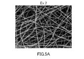
- 4 is an SEM image showing the result of observing the fiber of Example 2 at a magnification of 3000 times.
- 10 is an SEM image showing the result of observing the fiber of Example 2 at a magnification of 10000 times.
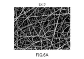
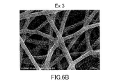
- 10 is an SEM image showing the result of observing the fiber of Example 3 at a magnification of 3000 times.
- 10 is an SEM image showing the result of observing the fiber of Example 3 at a magnification of 10000 times.
- 10 is an SEM image showing the result of observing the fiber of Example 4 at a magnification of 3000 times.
- 10 is an SEM image showing the result of observing the fiber of Example 4 at a magnification of 10000 times.
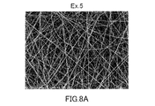
- 10 is an SEM image showing the result of observing the fiber of Example 5 at a magnification of 3000 times.
- 10 is an SEM image showing the result of observing the fiber of Example 5 at a magnification of 10000 times.
- 10 is an SEM image showing the result of observing the fiber of Example 6 at a magnification of 3000 times.
- 10 is an SEM image showing the result of observing the fiber of Example 6 at a magnification of 10000 times.
- 10 is an SEM image showing the result of observing the fiber of Example 7 at a magnification of 3000 times.
- 10 is an SEM image showing the result of observing the fiber of Example 7 at a magnification of 10000 times.
- 11 is an SEM image showing the result of observing the fiber of Example 11 at a magnification of 10000 times.
- 11 is an SEM image showing the result of observing the fiber of Example 15 at a magnification of 10000 times.
- 11 is an SEM image showing the results of observing the fiber of Example 16 at a magnification of 10000 times.
- 11 is an SEM image showing the results of observing the fiber of Example 17 at a magnification of 10000 times.
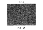
- 10 is an SEM image showing the result of observing the film obtained in Comparative Example 2 at a magnification of 2000 times.
- 10 is an SEM image showing the result of observing the film obtained in Comparative Example 2 at a magnification of 10,000.
- 10 is an SEM image showing the result of observing the film obtained in Comparative Example 3 at a magnification of 2000 times.
- 10 is an SEM image showing the result of observing the film obtained in Comparative Example 4 at a magnification of 3000 times.
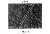
- 10 is an SEM image showing the result of observing the film obtained in Comparative Example 5 at a magnification of 3000 times.
- the fiber F of this embodiment contains a polymer P having amino groups. Fibers F are preferably nanofibers having an average fiber diameter of 1 to 1000 nm.
- the polymer P has the function of adsorbing acidic gases due to its amino groups.
- the polymer P contains, for example, at least one amino group selected from the group consisting of a primary amino group, a secondary amino group and a tertiary amino group.
- the polymer P preferably contains at least one selected from the group consisting of a primary amino group and a secondary amino group, and particularly preferably contains a secondary amino group.
- the amino groups possessed by the polymer P preferably contain secondary amino groups.
- Polymer P having a secondary amino group also tends to easily desorb adsorbed acidic gases. That is, according to the polymer P having a secondary amino group, the fiber F can be regenerated under relatively mild conditions.
- Another aspect of the present invention provides a fiber F containing a polymer P having a secondary amino group.
- the polymer P may contain a tertiary amino group, but may not contain a tertiary amino group.
- the content of amino groups, particularly primary amino groups or secondary amino groups, in the polymer P is, for example, 10 wt% or more, preferably 30 wt% or more.
- the upper limit of the content of amino groups in the polymer P is not particularly limited, and is, for example, 80 wt%.
- the polymer P may contain functional groups other than amino groups.
- Other functional groups include, for example, hydroxyl groups, ether groups, ester groups, amide groups, etc., with hydroxyl groups being preferred.
- the polymer P may consist only of hydrocarbon groups, amino groups and hydroxyl groups.
- the polymer P is not particularly limited as long as it has an amino group, and examples thereof include amine polymers containing structural units derived from epoxy monomers.
- the amine polymer contains, for example, at least one selected from the group consisting of a reactant P1 of a group of compounds containing an amine monomer and an epoxy monomer, and a reactant P2 of a group of compounds containing an amine prepolymer and an epoxy monomer.
- Other examples of the polymer P include a reactant P3 of a group of compounds containing an amine monomer and an epoxy prepolymer, a polymer P4 containing a structural unit derived from an aziridine, and a structural unit derived from an amino group-containing (meth)acrylate.
- Polymer P preferably contains at least one of reactants P1 to P3, and more preferably contains reactant P1, from the viewpoint of thermal stability and the like.
- the group of compounds for forming reactant P1 includes amine monomers and epoxy monomers, as described above.
- the reactant P1 is, for example, a polymer of a monomer group containing an amine monomer and an epoxy monomer, and particularly preferably a polymer of an amine monomer and an epoxy monomer.
- An amine monomer is a monomer containing at least one amino group, for example, at least one primary amino group.
- the number of primary amino groups contained in the amine monomer is preferably 2 or more, may be 3 or more, or may be 4 or more.
- the upper limit of the number of primary amino groups is not particularly limited, and is 10, for example.
- the amine monomer may contain a secondary amino group or a tertiary amino group in addition to the primary amino group.
- the molecular weight of the amine monomer is not particularly limited, and is, for example, less than 1000, preferably 500 or less.
- amine monomers examples include ethylamine, ethylenediamine, 1,4-butylenediamine, 1,5-pentanediamine, 1,6-hexanediamine, 1,7-heptanediamine, 1,8-octanediamine, diethylenetriamine, and triethylene.
- the amine monomer comprises an alipha
- the epoxy monomer contains, for example, at least one epoxy group.
- the number of epoxy groups contained in the epoxy monomer is preferably 2 or more, may be 3 or more, or may be 4 or more.
- the upper limit of the number of epoxy groups contained in the epoxy monomer is not particularly limited, and is 10, for example.
- the molecular weight of the epoxy monomer is not particularly limited, and is, for example, less than 1000, preferably 500 or less.
- epoxy monomers examples include n-butyl glycidyl ether, higher alcohol glycidyl ether, allyl glycidyl ether, 2-ethylhexyl glycidyl ether, phenyl glycidyl ether, cresyl glycidyl ether, p-sec-butylphenyl glycidyl ether, t-butylphenyl monofunctional epoxy compounds such as glycidyl ether; diepoxyalkanes such as 1,5-hexadiene diepoxide, 1,7-octadiene diepoxide and 1,9-decadiene diepoxide; (poly)ethylene glycol diglycidyl ether, ( Poly) propylene glycol diglycidyl ether, 1,4-butanediol diglycidyl ether, neopentyl glycol diglycidyl ether, 1,6-hexanedio
- the epoxy monomer preferably contains at least one selected from the group consisting of diepoxyalkanes and amino group-containing polyfunctional epoxy compounds, and more preferably contains diepoxyalkanes.
- a combination of 1,7-octadiene diepoxide (ODE) and 1,3-bis(N,N-diglycidylaminomethyl)cyclohexane may be used as epoxy monomers.
- Epoxy monomers may include ether group-containing polyfunctional epoxy compounds such as ethylene glycol diglycidyl ether (EDE), pentaerythritol tetraglycidyl ether (PETG), glycerol polyglycidyl ether, sorbitol polyglycidyl ether, and the like.
- a monofunctional epoxy compound When using a monofunctional epoxy compound, it is preferable to use it in combination with another epoxy monomer containing two or more epoxy groups.
- a monofunctional epoxy compound can also be used as a reactive diluent for adjusting the viscosity of the fiber F raw material.
- the reactant P1 contains, for example, a structural unit U1 derived from an amine monomer and a structural unit U2 derived from an epoxy monomer.
- the content of the structural unit U1 in the reactant P1 is, for example, 30 wt% or more, preferably 50 wt% or more.
- the upper limit of the content of the structural unit U1 in the reactant P1 is not particularly limited, and is, for example, 80 wt%.
- the content of structural unit U2 in reactant P1 is, for example, 20 wt % to 70 wt %.
- the group of compounds for forming reactant P2 includes amine prepolymers and epoxy monomers, as described above.
- the reactant P2 is, for example, a product obtained by cross-linking an amine prepolymer with an epoxy monomer (cross-linked product).
- the amine prepolymer for forming reactant P2 contains, for example, at least one amino group, especially a primary amino group.
- the number of primary amino groups contained in the amine prepolymer is preferably 2 or more, may be 3 or more, or may be 4 or more.
- the upper limit of the number of primary amino groups is not particularly limited, and is 100, for example.
- the amine prepolymer may contain secondary amino groups and tertiary amino groups in addition to primary amino groups.
- the weight average molecular weight of the amine prepolymer is not particularly limited, and may be, for example, 200 or more, 300 or more, 500 or more, 1000 or more, or even 1500 or more.
- the upper limit of the weight average molecular weight of the amine prepolymer is not particularly limited, and is 5,000, for example.
- Amine prepolymers include, for example, aliphatic polyamines such as polyethyleneimine and polyalkylenepolyamine; (meth)acrylic polymers having amino groups such as aminoethylated acrylic polymers; formed by reaction of polyamines and dimer acid and aliphatic polyamidoamines.
- the amine prepolymer comprises an aliphatic polyamine, especially polyethyleneimine (PEI).
- PEI polyethyleneimine
- An amine prepolymer can be used individually or in combination of 2 or more types.
- Epoxy monomers for forming reactant P2 include those described above for reactant P1.
- the reactant P2 contains, for example, a structural unit U2 derived from an epoxy monomer.
- the content of structural unit U2 in reactant P2 is, for example, 20 wt % to 70 wt %.
- the group of compounds for forming reactant P3 includes amine monomers and epoxy prepolymers, as described above.
- the reactant P3 is, for example, an epoxy prepolymer crosslinked with an amine monomer (crosslinked product).
- Amine monomers for forming reactant P3 include those described above for reactant P1.
- the epoxy prepolymer contains, for example, at least one epoxy group.
- the number of epoxy groups contained in the epoxy prepolymer is preferably 2 or more, may be 3 or more, or may be 4 or more.
- the upper limit of the number of epoxy groups contained in the epoxy prepolymer is not particularly limited, and is 100, for example.
- the weight average molecular weight of the epoxy prepolymer is not particularly limited, and is, for example, 1,000 to 50,000.
- Epoxy prepolymers include, for example, aromatic epoxy resins and non-aromatic epoxy resins.
- Aromatic epoxy resins include polyphenyl-based epoxy resins, epoxy resins containing fluorene rings, epoxy resins containing triglycidyl isocyanurate, and epoxy resins containing heteroaromatic rings (eg, triazine rings).
- Polyphenyl-based epoxy resins include bisphenol A type epoxy resin, brominated bisphenol A type epoxy resin, bisphenol F type epoxy resin, bisphenol AD type epoxy resin, stilbene type epoxy resin, biphenyl type epoxy resin, bisphenol A novolak type epoxy resin.
- Non-aromatic epoxy resins include aliphatic glycidyl ether type epoxy resins, aliphatic glycidyl ester type epoxy resins, alicyclic glycidyl ether type epoxy resins, alicyclic glycidyl amine type epoxy resins, and alicyclic glycidyl ester type epoxy resins. etc.
- An epoxy prepolymer can be used individually or in combination of 2 or more types.
- the glass transition temperature Tg of the polymer P, particularly the reactants P1 to P3, is not particularly limited, and is, for example, 40° C. or lower, preferably 30° C. or lower, more preferably 20° C. or lower, and still more preferably 10° C. °C or less.
- the lower limit of the glass transition temperature Tg of the polymer P is preferably ⁇ 100° C. from the viewpoint of ensuring sufficient acid gas adsorption in the fiber F.
- the glass transition temperature Tg means a midpoint glass transition temperature (T mg ) determined according to JIS K7121:1987.
- the reactants P1 to P3 usually correspond to thermosetting resins.
- the blending ratio of the amine compound (amine monomer or amine prepolymer) and the epoxy compound (epoxy monomer or epoxy prepolymer) is determined by the active hydrogen of the primary amino group contained in the amine compound. It is preferable to set the ratio of the equivalent weight of the epoxy group contained in the epoxy compound to the equivalent weight of the epoxy group to be, for example, 1 or less, preferably 0.9 or less, and more preferably 0.5 or less.
- the polymer P4 contains structural units U3 derived from aziridines.
- the polymer P4 may contain the structural unit U3 as a main component, or may be substantially composed only of the structural unit U3.
- the term "main component" means the structural unit that is the most contained on a weight basis among all the structural units that constitute the polymer.
- Aziridines are typically ethyleneimine.
- a specific example of polymer P4 is polyethyleneimine.
- the polymer P4 may be linear polyethyleneimine or branched polyethyleneimine.
- the polymer P5 contains a structural unit U4 derived from an amino group-containing (meth)acrylate.
- the polymer P5 may contain the structural unit U4 as a main component, or may be substantially composed only of the structural unit U4.
- amino group-containing (meth)acrylates include aminoalkyl (meth)acrylates such as aminoethyl (meth)acrylate, N-methylaminoethyl (meth)acrylate, and t-butylaminoethyl (meth)acrylate.
- the weight average molecular weight of the polymer P is not particularly limited, and is, for example, 500 or more, preferably 1000 or more, more preferably 10000 or more, still more preferably 100000 or more.
- the upper limit of the weight average molecular weight of polymer P is, for example, 10,000,000.
- the content of the polymer P in the fiber F is, for example, 10 wt% or more, preferably 30 wt% or more, more preferably 40 wt% or more, still more preferably 50 wt% or more, or even 55 wt% or more. It may be 60 wt% or more.
- the upper limit of the polymer P content is not particularly limited, and is, for example, 90 wt%, may be 80 wt%, or may be 70 wt%.
- the fiber F may further contain a thermoplastic resin T.
- the thermoplastic resin T has solubility in water, for example.
- “the thermoplastic resin T has solubility” means that 1 g or more of the thermoplastic resin T can be dissolved in the solvent at 95°C with respect to 100 g of the solvent mentioned.
- it means that 1 g or more of the thermoplastic resin T can be dissolved in the mentioned solvent for 100 g of the solvent under the condition of 23°C.
- the thermoplastic resin T may have solubility in alcohol, especially lower alcohol.
- thermoplastic resin T examples include polyvinyl alcohol resin, polyvinylpyrrolidone resin, polyurethane resin, (meth)acrylic resin, polyester resin, polyether resin, and the like.
- the thermoplastic resin T can be used alone or in combination of two or more.
- the thermoplastic resin T preferably contains at least one selected from the group consisting of polyvinyl alcohol resin, polyvinylpyrrolidone resin and polyether resin, and particularly preferably contains polyvinyl alcohol resin.
- polyether resins include polyethylene glycol and polyethylene oxide.
- the weight average molecular weight of the thermoplastic resin T is not particularly limited, and is, for example, 1000-10000000.
- the content of the thermoplastic resin T in the fiber F is not particularly limited, and is, for example, 90 wt% or less, preferably 70 wt% or less, more preferably 60 wt% or less, further preferably 50 wt% or less, It may be 45 wt% or less, or 40 wt% or less.
- the lower limit of the content of the thermoplastic resin T is, for example, 10 wt %, may be 20 wt %, or may be 30 wt %, from the viewpoint that the fiber F can be easily produced.
- the ratio of the weight of the polymer P to the total value of the weight of the polymer P and the weight of the thermoplastic resin T is, for example, 5 wt% or more from the viewpoint of improving the adsorption of acidic gas in the fiber F, It is preferably 10 wt% or more, more preferably 30 wt% or more, still more preferably 40 wt% or more, particularly preferably 50 wt% or more, and may be 55 wt% or more, or 60 wt% or more. good too.
- the upper limit of this ratio is not particularly limited, and is, for example, 90 wt%, may be 80 wt%, or may be 70 wt%.
- the fiber F may be substantially composed only of the polymer P and the thermoplastic resin T, but may further contain components other than the polymer P and the thermoplastic resin T.
- components include reaction accelerators, plasticizers, fillers, pigments, dyes, antioxidants, conductive materials, antistatic agents, ultraviolet absorbers, flame retardants, antioxidants, surfactants, and the like. be done.
- a reaction accelerator is utilized when synthesizing the polymer P, for example.
- reaction accelerators include tertiary amines such as triethylamine and tributylamine; imidazoles such as 2-phenol-4-methylimidazole, 2-ethyl-4-methylimidazole, and 2-phenol-4,5-dihydroxyimidazole. is mentioned.
- reaction accelerators can, for example, accelerate the reaction for synthesizing a polymer of amine monomers and epoxy monomers.
- the plasticizer include polyethylene glycol having a low molecular weight (for example, a weight average molecular weight of less than 1000).
- the fiber F contains a plasticizer, the plasticization of the polymer P tends to improve the diffusivity of the acid gas inside the polymer P.
- the adsorption speed of the acidic gas by the fibers F and the desorption speed of the acidic gas from the fibers F tend to be improved.
- the density d of the nitrogen element in the fiber F is not particularly limited, and is, for example, 1 mmol/g or more, preferably 3 mmol/g or more, more preferably 5 mmol/g or more, and still more preferably 7 mmol/g or more. is.
- the upper limit of the density d of the nitrogen element is not particularly limited, and is, for example, 50 mmol/g, and may be 20 mmol/g.
- the density d of the nitrogen elements can be regarded as the density of the amino groups in the fiber F.
- Another aspect of the present invention provides a fiber F having an amino group density of 1 mmol/g or more.
- the weight ratio w (N ratio) of the nitrogen element contained in the fiber F is not particularly limited, and is, for example, 5 wt% or more, 7 wt% or more, 9 wt% or more, 10 wt% or more, 11 wt% or more, 12 wt% or more. , 13 wt % or more, 14 wt % or more, or even 15 wt % or more.
- the upper limit of the weight ratio w is, for example, 50 wt%, and may be 30 wt%.
- the ratio of the amount of the nitrogen element contained in the fiber F to the amount of all elements constituting the fiber F is not particularly limited, and is, for example, 1 mol % or more, preferably 5 mol % or more, It is more preferably 7 mol % or more, may be 8 mol % or more, may be 9 mol % or more, or may be 10 mol % or more.
- the upper limit of this ratio is not particularly limited, and is, for example, 30 mol %.
- the substance amount of each element constituting the fiber F can be measured by performing elemental mapping on the cross section of the fiber F. FIG. Elemental mapping can be performed by observing the cross section of the fiber F with a transmission electron microscope and performing energy dispersive X-ray analysis (EDX).
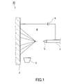
- the fiber F can be produced, for example, using the production apparatus 10 shown in FIG.
- a manufacturing apparatus 10 includes a discharge section 1 and a collection section 2 .
- the discharge part 1 is separated from the collection part 2 via the space 6, and can discharge the raw material M of the fiber F toward the collection part 2, for example.
- the discharge section 1 can discharge the discharge material 5 containing the raw material M toward the collection section 2 .
- the discharge part 1 faces the collection part 2, for example.
- the discharge portion 1 and the collection portion 2 are arranged in the horizontal direction. However, the discharge part 1 and the collection part 2 may be arranged in the vertical direction.
- the discharge part 1 may be positioned above the collecting part 2 or may be positioned below the collecting part 2 .
- the distance between the discharge part 1 and the collection part 2 is not particularly limited, and is, for example, 5 cm to 15 cm.
- a specific example of the ejection part 1 is a nozzle.
- the ejection part 1 may be a syringe.
- the collecting section 2 collects the fibers F formed in the spaces 6 .
- the collecting part 2 may be a plate-like member, but is preferably a winding roll capable of winding the fiber F from the viewpoint of mass productivity.
- Materials for the discharge part 1 and the collection part 2 are not particularly limited, and examples thereof include conductive materials such as metals.
- the manufacturing apparatus 10 may further include a heating unit 3 and a power supply 4.
- the heating part 3 can heat the discharge material 5 discharged from the discharge part 1 in the space 6 , particularly in the space 6 near the collecting part 2 .
- the heating unit 3 is preferably a non-contact type heater such as a dryer, heat gun, or lamp heater.
- the manufacturing apparatus 10 may include a light-emitting element (not shown) that emits light such as ultraviolet light instead of or together with the heating unit 3 .
- the power supply 4 is electrically connected to each of the ejection section 1 and the collection section 2 and can apply voltage to the ejection section 1 and the collection section 2 .
- the discharge section 1 is configured such that when a voltage is applied to the discharge section 1 , a voltage is also applied to the raw material M accommodated in the discharge section 1 .
- Examples of the power source 4 include an AC-DC converter, a power generator, and a battery.
- a manufacturing apparatus 10 equipped with a power supply 4 is suitable for the electrospinning method.
- a spinning method other than the electrospinning method may be performed.
- Other spinning methods include a dry spinning method and a zeta spinning method in which high-temperature air is blown onto the spout 5 spouted from the spouting section 1 .
- a raw material M having a compound group containing at least one selected from the group consisting of monomers and prepolymers is discharged from the discharge part 1, and the discharge 5 is discharged to the collection part 2. and applying energy to the compounds contained in the discharge 5 to react the compounds in the space 6 between the discharge part 1 and the collection part 2 to form a polymer. .
- the compound group includes compounds for forming the polymer P described above.
- the compound group preferably contains amine monomers and epoxy monomers as monomers.
- the compound group may contain an amine prepolymer or an epoxy prepolymer as the prepolymer.
- the compound group includes at least one selected from the group consisting of amine monomers and amine prepolymers, and may further include an epoxy monomer.
- the raw material M further contains, for example, the thermoplastic resin T described above.
- the thermoplastic resin T According to the thermoplastic resin T, the viscosity of the raw material M can be appropriately adjusted, which tends to facilitate the production of the fibers F. Furthermore, since the thermoplastic resin T is easily electrified, the raw material M containing the thermoplastic resin T is easily applied to the electrospinning method.
- a polyvinyl alcohol resin as the thermoplastic resin T has high compatibility with the polymer P, particularly the reactants P1 to P3 described above, and is suitable for the production method of the present embodiment.
- the raw material M may further contain a solvent.
- solvents include water, alcohols, particularly lower alcohols, and the like.
- the raw material M preferably contains water as a solvent.
- the raw material M may further contain components other than the compound group, the thermoplastic resin T and the solvent.
- Other components include, for example, the above-mentioned reaction accelerator, polymerization initiator, plasticizer, filler, and the like.
- the solid content concentration in the raw material M is not particularly limited, and is, for example, 50 wt% or less, preferably 30 wt% or less, more preferably 20 wt% or less.
- the average fiber diameter of the fibers F tends to decrease as the solid content concentration in the raw material M decreases.
- the lower limit of the solid content concentration in the raw material M is not particularly limited, and is, for example, 3 wt%, and may be 5 wt%.
- the raw material M is discharged from the discharge section 1 while a voltage is applied to the raw material M.
- the voltage application to the raw material M can be performed by applying a voltage to the ejection section 1 from the power supply 4 .
- the magnitude of the voltage applied to the raw material M is not particularly limited, and is, for example, 5-20 kV.
- a voltage is applied to the raw material M
- a conical Taylor cone composed of the discharged material 5 is formed near the outlet of the raw material M in the discharge section 1 .
- the composition of the ejected matter 5 constituting the Taylor cone is usually the same as the composition of the raw material M.
- a linear body composed of the discharge material 5 is discharged toward the space 6 from the tip of the Taylor cone.
- energy is applied to the compound group contained in the discharge 5 as the linear body to cause the compound group to react.
- the energy applied to the compound group is preferably thermal energy.
- the energy applied to the compound group may be light energy.
- thermal energy can be applied to the compound group by heating the discharge 5 in the space 6 .
- the compounds can be reacted by heating the discharge at a temperature of 70°C to 200°C.
- the heating temperature of the discharge 5 is preferably 200° C. or lower, more preferably 180° C. or lower, may be 160° C. or lower, or may be 140° C. or lower.
- the heating temperature of the discharge 5 may be 100° C. or higher. Heating of the discharge material 5 can be performed by the heating unit 3 .
- a reaction of a group of compounds is typically a polymerization reaction of a monomer.
- the reaction of the compound group may be a cross-linking reaction of the prepolymer.
- the reaction of the compound group proceeds in the space 6 to form the polymer P.
- a fiber F is thus obtained in the space 6 .
- the fiber F moves from the space 6 to the collecting section 2 and is collected by the collecting section 2 .
- a non-woven fabric may be formed by depositing the fibers F on the collection part 2 . That is, the present invention provides a nonwoven fabric containing fibers F from another aspect thereof.
- the polymer P is formed by reacting the compound group in the space 6 between the discharge section 1 and the collection section 2 . Therefore, according to the manufacturing method of this embodiment, the fiber F can be easily manufactured regardless of the type of the polymer P.
- the method of manufacturing the fiber F is not limited to the one described above.
- the fiber F having the polymer P4 containing structural units derived from aziridines can be produced by the method described above using the raw material M containing the polymer P4 instead of the monomer or prepolymer.
- the reaction of the compound group (polymer P4) does not proceed in the space 6 between the discharge section 1 and the collection section 2 . Therefore, it is not always necessary to apply energy to the discharge 5 in the space 6 .
- Fiber F tends to have high adsorptivity for acidic gases such as carbon dioxide.
- the adsorption amount A1 of carbon dioxide is 0.1 mmol/g or more when the fiber F is brought into contact with a mixed gas G composed of carbon dioxide, nitrogen, and water vapor for 15 hours.
- the adsorption amount A1 of carbon dioxide is preferably 0.3 mmol/g or more, 0.5 mmol/g or more, 0.7 mmol/g or more, 0.8 mmol/g or more, 0.9 mmol/g or more, and 1.0 mmol/g.
- the upper limit of the carbon dioxide adsorption amount A1 is not particularly limited, and is, for example, 10 mmol/g.
- the fiber F of this embodiment tends to have a high adsorption speed for acidic gases such as carbon dioxide.
- the adsorption speed of the fiber F can be evaluated by the ratio R of the adsorption amount A2 (mmol/g) of carbon dioxide when the fiber F is brought into contact with the mixed gas G for 60 minutes to the adsorption amount A1 (mmol/g).
- the ratio R is, for example, 20% or more, and may be 30% or more, 40% or more, 50% or more, 60% or more, 70% or more, or even 80% or more.
- the upper limit of the ratio R is not particularly limited, and is, for example, 100%, and may be 80% in some cases.
- the adsorption amount A2 of carbon dioxide is, for example, 0.05 mmol/g or more, preferably 0.1 mmol/g or more, more preferably 0.2 mmol/g or more, and still more preferably 0.3 mmol/g. g or more, particularly preferably 0.4 mmol/g or more, may be 0.5 mmol/g or more, may be 0.6 mmol/g or more, or may be 0.7 mmol/g or more. good too.
- the upper limit of the carbon dioxide adsorption amount A2 is not particularly limited, and is, for example, 5 mmol/g.
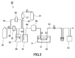
- the adsorption amounts A1 and A2 can be measured using, for example, the measuring device 20 shown in FIG.
- the measuring device 20 has a first tank 30 and a second tank 31 .
- the first tank 30 stores dry nitrogen
- the second tank 31 stores a mixed gas of dry nitrogen and dry carbon dioxide.
- the concentration of carbon dioxide in the mixed gas in the second tank 31 is, for example, 5 vol %.
- the measuring device 20 further comprises a first container 40 containing water 70 and a first path 60 for sending nitrogen from the first tank 30 to the first container 40 .
- the first path 60 has one end connected to the gas outlet of the first tank 30 and the other end located in the water 70 of the first container 40 .
- Nitrogen sent from the first tank 30 to the first container 40 is humidified by contact with water 70 .
- a mass flow controller 35 for adjusting the flow rate of nitrogen sent from the first tank 30 to the first container 40 is arranged in the first path 60 .
- the measuring device 20 further includes a second container 41 , a second path 62 and a bypass path 61 .
- a second path 62 connects the first container 40 and the second container 41 .
- the nitrogen that has been sent to the first container 40 and humidified is sent to the second container 41 through the second path 62 .
- the bypass path 61 branches off from the first path 60 and connects to the second path 62 at a position between the first tank 30 and the mass flow controller 35 . Part of the nitrogen sent from the first tank 30 flows into the bypass line 61 and is sent to the second container 41 through the second line 62 .
- a mass flow controller 36 for adjusting the flow rate of nitrogen sent from the first tank 30 to the bypass route 61 is arranged in the bypass route 61 .
- the measuring device 20 further includes a third path 63 for sending the mixed gas from the second tank 31 to the second path 62 .
- the third path 63 has one end connected to the gas outlet of the second tank 31 and the other end connected to the second path 62 .
- a mass flow controller 37 for adjusting the flow rate of the mixed gas sent from the second tank 31 to the second path 62 is arranged on the third path 63 .
- the mixed gas sent to the second path 62 is sent to the second container 41 through the second path 62 .
- the measuring device 20 further comprises a third container 42 and a fourth channel 64.
- the third container 42 contains water 71 and the adsorption section 21 arranged in the water 71 .
- the temperature of the water 71 is maintained at 23°C in the third container 42 .
- the adsorption part 21 has a gas inlet 22 and a gas outlet 23 .
- the adsorption part 21 functions as a container that accommodates the fiber F therein.
- the adsorption part 21 is configured so that the water 71 does not permeate inside.
- the adsorption section 21 is typically a tube made of a hydrophobic resin such as a fluorine resin such as tetrafluoroethylene-perfluoroalkoxyethylene copolymer (PFA).
- the tube as the adsorption part 21 has an inner diameter of 4 mm and an outer diameter of 6 mm.
- the suction unit 21 is configured to be detachable from the measuring device 20 .
- the measuring device 20 can also be used as an acidic gas adsorption device having the adsorption section 21 .
- the present invention provides an acidic gas adsorption device 20 comprising an adsorption section 21 having a gas inlet 22 and a gas outlet 23, the adsorption section 21 housing a fiber F therein.
- the fourth path 64 connects the second container 41 and the third container 42 . Specifically, the fourth path 64 is connected to the gas inlet 22 of the adsorption section 21 in the third container 42 .
- a first densitometer 50 for measuring the concentration of carbon dioxide in the gas supplied to the adsorption section 21 is arranged in the fourth path 64 .
- the measurement device 20 further includes a fifth path 65 connected to the gas outlet 23 of the adsorption section 21 and for discharging gas from the adsorption section 21 to the outside of the measurement device 20 .
- a second densitometer 51 for measuring the concentration of carbon dioxide in the gas discharged from the adsorption unit 21 is arranged on the fifth path 65 .
- a back pressure valve that adjusts the pressure in the adsorption section 21 to a constant value may be further arranged in the fifth path 65 .
- Each path of the measuring device 20 is composed of, for example, metal or resin piping.
- the fiber F is dried.
- the drying treatment is performed, for example, by treating the fiber F at 60° C. for 2 hours or more in a vacuum atmosphere.
- the adsorption section 21 is filled with the fibers F after the drying process.
- the weight of the fibers F filled in the adsorption section 21 is, for example, 50 mg.
- the fourth path 64 and the fifth path 65 are connected to both ends of the adsorption part 21 and the adsorption part 21 is immersed in the water 71 of the third container 42 .
- the nitrogen from the first tank 30 and the mixed gas from the second tank 31 are introduced into the second container 41 through the first path 60, the second path 62, the bypass path 61 and the third path 63 of the measuring device 20. supply to These gases are mixed in the second container 41 to obtain a mixed gas G composed of carbon dioxide, nitrogen and water vapor.
- a mixed gas G composed of carbon dioxide, nitrogen and water vapor.
- the mixed gas G has a temperature of 23° C. and a humidity of 50% RH.
- the mixed gas G is supplied to the adsorption section 21 through the fourth path 64 at a flow rate sufficient for the weight of the fibers F, for example, a flow rate of 300 mL/min for fibers F of 50 mg.
- the pressure of the mixed gas G is adjusted to 107 kPa, for example, by a back pressure valve.
- the adsorption section 21 is taken out from the third container 42, and the adsorption section 21 is immersed in a hot water bath (not shown) at 80°C for two hours or longer.
- the adsorption part 21 is immersed in the hot water bath until the concentration of carbon dioxide measured by the first densitometer 50 and the concentration of carbon dioxide measured by the second densitometer 51 become substantially the same value. .
- the pretreatment of the fibers F in the adsorption section 21 is completed.
- the substance amount M1 of carbon dioxide adsorbed by the fiber F within 15 hours from the start and the substance amount M2 of carbon dioxide adsorbed by the fiber F within 60 minutes from the start are measured.
- the substance amount of carbon dioxide adsorbed by the fiber F is the result of measuring the difference between the concentration of carbon dioxide measured by the first densitometer 50 and the concentration of carbon dioxide measured by the second densitometer 51 over time.
- the fiber F is composed only of a body portion containing a polymer P, for example. In other words, the fiber F does not have a covering layer covering the surface of the main body. Polymer P is uniformly present in fiber F, for example.
- the structure of the fiber F is not particularly limited.
- the fibers F may be short fibers or long fibers.
- the fiber F may or may not have a branched structure.
- the average fiber diameter of the fibers F is preferably 1-1000 nm.
- the average fiber diameter of the fiber F is preferably 700 nm or less, more preferably 600 nm or less, still more preferably 500 nm or less, may be 450 nm or less, may be 400 nm or less, or may be 300 nm or less. 250 nm or less, 200 nm or less, or 150 nm or less.
- the smaller the average fiber diameter of the fibers F the more the adsorption speed of the acidic gas in the fibers F increases.
- the average fiber diameter of fiber F can be specified by the following method. First, a plurality of fibers F are observed with a scanning electron microscope. In the obtained electron microscope image, the fiber diameters of at least 15 fibers F are calculated by image processing. The average value of the obtained calculated values can be regarded as the average fiber diameter of the fibers F.
- the heat resistance of the fiber F tends to be improved.
- the fiber F of this embodiment is suitable for an acidic gas adsorbent.
- Acid gases include carbon dioxide, hydrogen sulfide, carbonyl sulfide, sulfur oxides (SOx), hydrogen cyanide, nitrogen oxides (NOx), etc.
- Carbon dioxide is preferred.
- the use of the fiber F is not limited to use as an acid gas adsorbent.
- Fiber F can be used, for example, by the following method.
- First, the fiber F is brought into contact with a mixed gas containing an acidic gas.
- Mixed gas contains other gas other than acidic gas, for example.
- gases include, for example, hydrogen, non-polar gases such as nitrogen, and inert gases such as helium, preferably nitrogen.
- the mixed gas is typically atmospheric air.
- the mixed gas may be the off-gas of a chemical plant or a thermal power plant.
- the temperature of the mixed gas is, for example, room temperature (23°C).
- the concentration of the acid gas in the mixed gas is not particularly limited, and is, for example, 0.01 vol% (100 volppm) or more, preferably 0.04 vol% (400 volppm) or more under standard conditions (0°C, 101 kPa). It may be 0 vol % or more.
- the upper limit of the concentration of carbon dioxide in the mixed gas is not particularly limited, and is, for example, 10 vol % under standard conditions.
- the pressure of the mixed gas is typically equal to the atmospheric pressure in the fiber F environment. However, the mixed gas brought into contact with the fiber F may be pressurized.
- the fiber F in contact with the mixed gas adsorbs the acid gas contained in the mixed gas.
- the operation of bringing the mixed gas into contact with the fibers F is performed, for example, until the adsorption of the acidic gas by the fibers F reaches equilibrium.
- the regeneration treatment can be carried out by heating the fiber F, for example.
- the heating temperature of the fiber F is, for example, 50-80.degree.
- the fiber F may be heated under a reduced pressure atmosphere or under a vacuum atmosphere.
- the acid gas is desorbed from the fiber F.
- the acid gas desorbed from the fiber F especially carbon dioxide, can be used as raw materials for synthesizing chemicals and dry ice.
- the operation of adsorbing the acidic gas by the fiber F and the regeneration treatment of the fiber F can be performed using the measuring device 20 (acid gas adsorbing device) described above.
- the fiber sheet of this embodiment contains the fibers F described above.
- the fiber sheet is an aggregate of a plurality of fibers F.
- the fiber sheet may consist essentially of fibers F only.
- the fiber sheet may be a woven fabric or a non-woven fabric.
- the shape of the fiber sheet is not particularly limited, and examples thereof include a flat plate shape, a corrugated shape, and a pleated shape.
- two or more fibers F may be welded together at the intersections.
- the strength of the fiber sheet tends to be improved.
- the fibers F do not have to be welded to each other.
- the structure 15 of this embodiment includes the above-described fiber sheet 11 and has ventilation paths 14 .
- the structure 15 is typically a honeycomb structure having a plurality of ventilation channels 14 extending in the same direction.
- the structure 15 includes an adsorbent unit U in which, for example, a corrugated fiber sheet 11A and a flat plate-shaped fiber sheet 11B are laminated.
- a plurality of peaks 12 and a plurality of valleys 13 are arranged alternately. Ventilation paths 14 are formed between the peaks 12 or valleys 13 of the fiber sheet 11A and the fiber sheet 11B.
- the direction x is the direction (wave direction) in which the plurality of peaks 12 and the plurality of valleys 13 of the fiber sheet 11A are alternately arranged.
- the direction y is the lamination direction of the fiber sheets 11A and 11B in the adsorbent unit U.
- a direction z is a direction perpendicular to each of the directions x and y, and is the direction in which the ventilation path 14 extends.
- the structure 15 includes a plurality of adsorbent units U, for example.
- the number of adsorbent units U in the structure 15 is not particularly limited, and is, for example, 2-100.
- the plurality of adsorbent units U are stacked in the direction y such that the plurality of fiber sheets 11A and the plurality of fiber sheets 11B are alternately arranged.
- the structure 15 has a block shape by stacking a plurality of adsorbent units U. As shown in FIG.
- the ventilation path 14 is a through hole that penetrates the structure 15 in the direction z.
- the ventilation path 14 is surrounded by fiber sheets 11A and 11B.
- the acid gas is efficiently adsorbed by the fiber sheets 11A and 11B while moving through the ventilation path 14 in the direction z.
- the structure 15 with a large cross-sectional area of the ventilation path 14 is suitable for reducing the pressure loss that occurs when it comes into contact with acid gas.
- a structure 15 with reduced pressure loss can, for example, reduce the power of a fan used to move acid gases.
- the shape of structure 15 including fiber sheet 11 is not limited to that shown in FIG. 3A.
- the structure 16 shown in FIG. 3B has a shape in which one adsorbent unit U is wound around the central tube 80 . Except for this, the configuration of structure 16 is the same as that of structure 15 .
- the structure 16 has a cylindrical shape.
- the plurality of peaks 12 and the plurality of valleys 13 of the fiber sheet 11A are alternately arranged in the circumferential direction of the structure 16 .
- Ventilation path 14 formed between peaks 12 or valleys 13 of fiber sheet 11A and fiber sheet 11B penetrates structure 16 in the direction in which central tube 80 extends.
- the acid gas is efficiently adsorbed by the fiber sheets 11A and 11B while moving through the ventilation path 14 in the direction in which the central tube 80 extends.
- Example 1 First, 1.24 g of triethylenetetramine (TETA manufactured by Sigma-Aldrich) was prepared as an amine monomer, and 1.00 g of 1,7-octadiene diepoxide (ODE manufactured by Tokyo Chemical Industry Co., Ltd.) was prepared as an epoxy monomer. , and 0.25 g of 1,3-bis(N,N-diglycidylaminomethyl)cyclohexane (TETRAD-C manufactured by Mitsubishi Gas Chemical Company, Inc.).
- TETA triethylenetetramine
- ODE 1,7-octadiene diepoxide
- TTRAD-C 1,3-bis(N,N-diglycidylaminomethyl)cyclohexane
- thermoplastic resin T 10 g of polyvinyl alcohol (PVA-217 manufactured by Kuraray Co., Ltd.; degree of saponification 88, degree of polymerization 1700) as thermoplastic resin T was dissolved in 90 g of pure water to obtain an aqueous solution having a concentration of 10 wt %. Next, this aqueous solution and the prepared monomer were mixed to prepare a raw material. In the raw materials, the ratio (blending ratio) of the weight of the aqueous solution of the thermoplastic resin T to the total weight of the amine monomer and the epoxy monomer was 9:1.
- the raw material was discharged from the discharge section 1 using the manufacturing apparatus 10 shown in FIG. At this time, a voltage of 10 kV was applied to the raw material.
- the distance between the discharge part 1 and the collection part 2 was 8 cm.
- a syringe was used as the ejection part 1 .
- an all-plastic syringe (5 mL) manufactured by HANKE, in which a non-beveled needle 22G manufactured by Terumo was set, was used as the ejection part 1 .
- the raw material was discharged by pushing the plunger of the syringe at a speed of 0.006 mm/min. In the space 6, the discharge 5 from the discharge section 1 was heated with a heat gun.
- the temperature of the air sent from the heat gun was 100°C.
- the polymerization reaction of the compound group (TETA, ODE and TETRAD-C) contained in the ejected material 5 proceeded to form a polymer P having an amino group.
- the fiber of Example 1 was formed in the space 6 . This fiber was collected by the collecting section 2 .
- Examples 2--7 Fibers of Examples 2 to 7 were obtained in the same manner as in Example 1, except that the heating temperature of the discharge 5 and the concentration of the thermoplastic resin T in the aqueous solution were changed as shown in Table 1. In Examples 2 and 5, the fibers were produced under the same conditions except that the temperature and humidity of the atmosphere in the manufacturing apparatus 10 were different.
- Example 8 First, 2.06 g of triethylenetetramine (TETA manufactured by Sigma-Aldrich) was prepared as an amine monomer, and 1.00 g of ethylene glycol diglycidyl ether (Denacol EX-810 manufactured by Nagase ChemteX Corporation) was prepared as an epoxy monomer. , and 1.50 g of pentaerythritol tetraglycidyl ether (Showfree PETG manufactured by Showa Denko KK) were prepared.
- TETA triethylenetetramine
- thermoplastic resin T 8 g of polyvinyl alcohol (PVA-117 manufactured by Kuraray Co., Ltd.; degree of saponification: 98, degree of polymerization: 1700) as thermoplastic resin T was dissolved in 92 g of pure water to obtain an aqueous solution with a concentration of 8 wt %. Next, this aqueous solution and the prepared monomer were mixed to prepare a raw material. In the raw materials, the ratio (blending ratio) of the weight of the aqueous solution of the thermoplastic resin T to the total weight of the amine monomer and the epoxy monomer was 8:1. A fiber of Example 8 was obtained in the same manner as in Example 1, except that this raw material was used and the heating temperature of the discharge 5 was changed to 120°C.
- PVA-117 manufactured by Kuraray Co., Ltd. degree of saponification: 98, degree of polymerization: 1700
- Example 9 First, 0.97 g of triethylenetetramine (TETA manufactured by Sigma-Aldrich) was prepared as an amine monomer, and 1.00 g of ethylene glycol diglycidyl ether (Denacol EX-810 manufactured by Nagase ChemteX Corporation) was prepared as an epoxy monomer. , and 0.25 g of glycerol polyglycidyl ether (Denacol EX-313 manufactured by Nagase ChemteX Corporation) were prepared.
- TETA triethylenetetramine
- thermoplastic resin T 8 g of polyvinyl alcohol (PVA-117 manufactured by Kuraray Co., Ltd.; degree of saponification: 98, degree of polymerization: 1700) as thermoplastic resin T was dissolved in 92 g of pure water to obtain an aqueous solution with a concentration of 8 wt %. Next, this aqueous solution and the prepared monomer were mixed to prepare a raw material. In the raw materials, the ratio (blending ratio) of the weight of the aqueous solution of the thermoplastic resin T to the total weight of the amine monomer and the epoxy monomer was 10:1. A fiber of Example 9 was obtained in the same manner as in Example 1 except that this raw material was used and the heating temperature of the discharge 5 was changed to 120°C.
- PVA-117 manufactured by Kuraray Co., Ltd. degree of saponification: 98, degree of polymerization: 1700
- Example 10 First, 1.40 g of polyethyleneimine (Epomin SP-006 manufactured by Nippon Shokubai Co., Ltd.) was prepared as an amine prepolymer, and 0.40 g of ethylene glycol diglycidyl ether (Denacol EX-810 manufactured by Nagase ChemteX Corporation) was prepared as an epoxy monomer. 70 g and 0.30 g of sorbitol polyglycidyl ether (Denacol EX-614B manufactured by Nagase ChemteX Corporation) were prepared.
- thermoplastic resin T 8 g of polyvinyl alcohol (PVA-117 manufactured by Kuraray Co., Ltd.; degree of saponification: 98, degree of polymerization: 1700) as thermoplastic resin T was dissolved in 92 g of pure water to obtain an aqueous solution with a concentration of 8 wt %. Next, this aqueous solution was mixed with the prepared prepolymer and monomer to prepare a raw material. In the raw materials, the ratio (blending ratio) of the weight of the aqueous solution of the thermoplastic resin T to the total weight of the amine prepolymer and the epoxy monomer was 8:1.
- a fiber of Example 10 was obtained in the same manner as in Example 1, except that this raw material was used and the heating temperature of the discharge 5 was changed to 120°C.
- Example 11 First, 1.40 g of polyethyleneimine (Epomin SP-006 manufactured by Nippon Shokubai Co., Ltd.) was prepared as an amine prepolymer, and 0.40 g of ethylene glycol diglycidyl ether (Denacol EX-810 manufactured by Nagase ChemteX Corporation) was prepared as an epoxy monomer. 70 g and 0.30 g of sorbitol polyglycidyl ether (Denacol EX-614B manufactured by Nagase ChemteX Corporation) were prepared.
- thermoplastic resin T 8 g of polyvinyl alcohol (PVA-117 manufactured by Kuraray Co., Ltd.; degree of saponification: 98, degree of polymerization: 1700) as thermoplastic resin T was dissolved in 92 g of pure water to obtain an aqueous solution with a concentration of 8 wt %. Next, this aqueous solution was mixed with the prepared prepolymer and monomer. Next, 0.16 g of polyethylene glycol (PEG400 manufactured by Fuji Film Wako Pure Chemical Industries, Ltd.) was further added as a plasticizer to prepare a raw material. In the raw materials, the ratio of the weight of the plasticizer to the total weight of prepolymer, monomer and thermoplastic resin T was 5 wt%.
- Example 11 In the raw materials, the ratio (blending ratio) of the weight of the aqueous solution of the thermoplastic resin T to the total weight of the amine prepolymer and the epoxy monomer was 9:1.
- a fiber of Example 11 was obtained in the same manner as in Example 1 except that this raw material was used and the heating temperature of the discharge 5 was changed to 120°C.
- Example 12 First, 1.59 g of polyethyleneimine (Epomin SP-006 manufactured by Nippon Shokubai Co., Ltd.) was prepared as an amine prepolymer, and 0.59 g of ethylene glycol diglycidyl ether (Denacol EX-810 manufactured by Nagase ChemteX Corporation) was prepared as an epoxy monomer. 80 g and 0.20 g of 1,3-bis(N,N-diglycidylaminomethyl)cyclohexane (TETRAD-C manufactured by Mitsubishi Gas Chemical Company, Inc.) were prepared.
- Epomin SP-006 manufactured by Nippon Shokubai Co., Ltd.
- thermoplastic resin T 8 g of polyvinyl alcohol (PVA-117 manufactured by Kuraray Co., Ltd.; degree of saponification: 98, degree of polymerization: 1700) as thermoplastic resin T was dissolved in 92 g of pure water to obtain an aqueous solution with a concentration of 8 wt %. Next, this aqueous solution was mixed with the prepared prepolymer and monomer to prepare a raw material. In the raw materials, the ratio (blending ratio) of the weight of the aqueous solution of the thermoplastic resin T to the total weight of the amine prepolymer and the epoxy monomer was 9:1.
- a fiber of Example 12 was obtained in the same manner as in Example 1 except that this raw material was used and the heating temperature of the discharge 5 was changed to 120°C.
- Example 13 First, 1.59 g of polyethyleneimine (Epomin SP-006 manufactured by Nippon Shokubai Co., Ltd.) was prepared as an amine prepolymer, and 0.59 g of ethylene glycol diglycidyl ether (Denacol EX-810 manufactured by Nagase ChemteX Corporation) was prepared as an epoxy monomer. 80 g and 0.20 g of 1,3-bis(N,N-diglycidylaminomethyl)cyclohexane (TETRAD-C manufactured by Mitsubishi Gas Chemical Company, Inc.) were prepared.
- Epomin SP-006 manufactured by Nippon Shokubai Co., Ltd.
- thermoplastic resin T 8 g of polyvinyl alcohol (PVA-117 manufactured by Kuraray Co., Ltd.; degree of saponification: 98, degree of polymerization: 1700) as thermoplastic resin T was dissolved in 92 g of pure water to obtain an aqueous solution with a concentration of 8 wt %. Next, this aqueous solution was mixed with the prepared prepolymer and monomer. Next, 0.22 g of polyethylene glycol (PEG400 manufactured by Fuji Film Wako Pure Chemical Industries, Ltd.) was further added as a plasticizer to prepare a raw material. In the raw materials, the ratio of the weight of the plasticizer to the total weight of prepolymer, monomer and thermoplastic resin T was 5 wt%.
- Example 13 In the raw materials, the ratio (blending ratio) of the weight of the aqueous solution of the thermoplastic resin T to the total weight of the amine prepolymer and the epoxy monomer was 9:1.
- a fiber of Example 13 was obtained in the same manner as in Example 1 except that this raw material was used and the heating temperature of the discharge 5 was changed to 120°C.
- Example 14 First, 1.64 g of polyethyleneimine (Epomin SP-006 manufactured by Nippon Shokubai Co., Ltd.) was prepared as an amine prepolymer, and ethylene glycol diglycidyl ether (Denacol EX-810 manufactured by Nagase ChemteX Corporation) was prepared as an epoxy monomer. 00g was prepared. Next, 8 g of polyvinyl alcohol (PVA-117 manufactured by Kuraray Co., Ltd.; degree of saponification: 98, degree of polymerization: 1700) as thermoplastic resin T was dissolved in 92 g of pure water to obtain an aqueous solution with a concentration of 8 wt %.
- polyethyleneimine Epomin SP-006 manufactured by Nippon Shokubai Co., Ltd.
- ethylene glycol diglycidyl ether Disacol EX-810 manufactured by Nagase ChemteX Corporation
- 00g was prepared.
- this aqueous solution was mixed with the prepared prepolymer and monomer to prepare a raw material.
- the ratio (blending ratio) of the weight of the aqueous solution of the thermoplastic resin T to the total weight of the amine prepolymer and the epoxy monomer was 9:1.
- a fiber of Example 14 was obtained in the same manner as in Example 1 except that this raw material was used and the heating temperature of the discharge 5 was changed to 120°C.
- Example 15 First, 1.00 g of polyethyleneimine (PEI manufactured by Sigma-Aldrich, weight average molecular weight of 750,000, 50 wt % aqueous solution) was prepared as a polymer containing structural units derived from aziridines. Next, 8 g of polyvinyl alcohol (PVA-117 manufactured by Kuraray Co., Ltd.; degree of saponification: 98, degree of polymerization: 1700) as thermoplastic resin T was dissolved in 92 g of pure water to obtain an aqueous solution with a concentration of 8 wt %. Next, this aqueous solution and the prepared polymer were mixed to prepare a raw material.
- PEI polyethyleneimine
- PVA-117 polyvinyl alcohol
- the ratio (blending ratio) of the weight of the aqueous solution of the thermoplastic resin T to the weight of the polymer was 9:1.
- a fiber of Example 15 was obtained in the same manner as in Example 1 except that this raw material was used and the heating temperature of the discharge 5 was changed to 50°C.
- Example 16 First, 0.42 g of polyethyleneimine (Epomin SP-003 manufactured by Nippon Shokubai Co., Ltd.) was prepared as a polymer containing structural units derived from aziridines. Next, 8 g of polyvinyl alcohol (PVA-117 manufactured by Kuraray Co., Ltd.; degree of saponification: 98, degree of polymerization: 1700) as thermoplastic resin T was dissolved in 92 g of pure water to obtain an aqueous solution with a concentration of 8 wt %. Next, this aqueous solution and the prepared polymer were mixed to prepare a raw material.
- polyethyleneimine Epomin SP-003 manufactured by Nippon Shokubai Co., Ltd.
- thermoplastic resin T 8 g of polyvinyl alcohol (PVA-117 manufactured by Kuraray Co., Ltd.; degree of saponification: 98, degree of polymerization: 1700) as thermoplastic resin T was dissolved in 92 g of pure water to obtain an aqueous
- Example 16 In the raw materials, the ratio (blending ratio) of the weight of the aqueous solution of the thermoplastic resin T to the weight of the polymer was 8:0.42.
- a fiber of Example 16 was obtained in the same manner as in Example 1 except that this raw material was used and the heating temperature of the discharge 5 was changed to 50°C.
- Example 17 First, 1.59 g of polyethyleneimine (Epomin SP-006 manufactured by Nippon Shokubai Co., Ltd.) was prepared as an amine prepolymer, and 0.59 g of ethylene glycol diglycidyl ether (Denacol EX-810 manufactured by Nagase ChemteX Corporation) was prepared as an epoxy monomer. 80 g and 0.20 g of 1,3-bis(N,N-diglycidylaminomethyl)cyclohexane (TETRAD-C manufactured by Mitsubishi Gas Chemical Company, Inc.) were prepared.
- thermoplastic resin T 10 g of polyvinylpyrrolidone (PVP K90 manufactured by Fuji Film Wako Pure Chemical Industries, Ltd.) as a thermoplastic resin T was dissolved in 90 g of pure water to obtain an aqueous solution with a concentration of 10 wt %. Next, this aqueous solution was mixed with the prepared prepolymer and monomer to prepare a raw material. In the raw materials, the ratio (blending ratio) of the weight of the aqueous solution of the thermoplastic resin T to the total weight of the amine prepolymer and the epoxy monomer was 9:1.
- a fiber of Example 17 was obtained in the same manner as in Example 1 except that this raw material was used and the heating temperature of the discharge 5 was changed to 120°C.
- Example 18 First, 1.59 g of polyethyleneimine (Epomin SP-006 manufactured by Nippon Shokubai Co., Ltd.) was prepared as an amine prepolymer, and 0.59 g of ethylene glycol diglycidyl ether (Denacol EX-810 manufactured by Nagase ChemteX Corporation) was prepared as an epoxy monomer. 80 g and 0.20 g of 1,3-bis(N,N-diglycidylaminomethyl)cyclohexane (TETRAD-C manufactured by Mitsubishi Gas Chemical Company, Inc.) were prepared.
- thermoplastic resin T 8 g of polyvinyl alcohol (PVA-117 manufactured by Kuraray Co., Ltd.; degree of saponification: 98, degree of polymerization: 1700) was dissolved in 92 g of pure water to obtain an aqueous solution with a concentration of 8 wt %.
- 10 g of polyethylene glycol (PEG20000 manufactured by Fuji Film Wako Pure Chemical Industries, Ltd.) as a thermoplastic resin T was dissolved in 90 g of pure water to obtain an aqueous solution with a concentration of 10 wt %.
- these aqueous solutions were mixed with the prepared prepolymers and monomers to prepare raw materials.
- Example 18 In the raw materials, the ratio (blending ratio) of the weight of the polyvinyl alcohol resin aqueous solution, the weight of the polyethylene glycol (polyether resin) aqueous solution, and the total weight of the amine prepolymer and the epoxy monomer was 8:1:1. .
- a fiber of Example 18 was obtained in the same manner as in Example 1 except that this raw material was used and the heating temperature of the discharge 5 was changed to 120°C.
- Example 19 First, 1.98 g of polyethyleneimine (Epomin SP-006 manufactured by Nippon Shokubai Co., Ltd.) was prepared as an amine prepolymer, and 0.98 g of ethylene glycol diglycidyl ether (Denacol EX-810 manufactured by Nagase ChemteX Corporation) was prepared as an epoxy monomer. 80 g and 0.20 g of 1,3-bis(N,N-diglycidylaminomethyl)cyclohexane (TETRAD-C manufactured by Mitsubishi Gas Chemical Company, Inc.) were prepared.
- thermoplastic resin T 8 g of polyvinyl alcohol (PVA-117 manufactured by Kuraray Co., Ltd.; degree of saponification: 98, degree of polymerization: 1700) as thermoplastic resin T was dissolved in 92 g of pure water to obtain an aqueous solution with a concentration of 8 wt %. Next, this aqueous solution was mixed with the prepared prepolymer and monomer to prepare a raw material. In the raw materials, the ratio (blending ratio) of the weight of the aqueous solution of the thermoplastic resin T to the total weight of the amine prepolymer and the epoxy monomer was 9:1.
- a fiber of Example 19 was obtained in the same manner as in Example 1 except that this raw material was used and the heating temperature of the discharge 5 was changed to 120°C.
- Example 20 First, 2.66 g of polyethyleneimine (Epomin SP-006, manufactured by Nippon Shokubai Co., Ltd.) was prepared as an amine prepolymer, and 0.66 g of ethylene glycol diglycidyl ether (Denacol EX-810, manufactured by Nagase ChemteX Corporation) was prepared as an epoxy monomer. 80 g and 0.20 g of 1,3-bis(N,N-diglycidylaminomethyl)cyclohexane (TETRAD-C manufactured by Mitsubishi Gas Chemical Company, Inc.) were prepared.
- thermoplastic resin T 7 g of polyvinyl alcohol (PVA-117 manufactured by Kuraray Co., Ltd.; degree of saponification: 98, degree of polymerization: 1700) as thermoplastic resin T was dissolved in 93 g of pure water to obtain an aqueous solution with a concentration of 7 wt %. Next, this aqueous solution was mixed with the prepared prepolymer and monomer to prepare a raw material. In the raw materials, the ratio (blending ratio) of the weight of the aqueous solution of the thermoplastic resin T to the total weight of the amine prepolymer and the epoxy monomer was 9:1.
- a fiber of Example 20 was obtained in the same manner as in Example 1 except that this raw material was used and the heating temperature of the discharge 5 was changed to 120°C.
- Comparative Example 3 An attempt was made to fabricate a fiber in the same manner as in Comparative Example 2, except that the ratio of the weight of the polyvinyl alcohol resin aqueous solution to the total weight of the amine monomer and the epoxy monomer (blending ratio) was changed to 8:2. However, no fiber was formed, and a film was formed on the collecting portion 2 .
- Comparative Example 4 Regarding the aqueous solution of polyvinyl alcohol resin, an attempt was made to prepare fibers by the same method as in Comparative Example 3, except that the solvent was changed to a mixed solvent of water and methanol. no film was formed.
- Comparative Example 5 An attempt was made to fabricate a fiber by the same method as in Comparative Example 2, except that after the ejected matter 5 was collected by the collecting portion 2, the ejected matter 5 was heated on the collecting portion 2 at 120°C. No fibers were formed, and a membrane was formed on the collecting part 2 .
- Average fiber diameter The average fiber diameter was measured for the fibers of Examples 1-20 by the method described above. Results are shown in Tables 1 and 2.
- the carbon dioxide adsorption amount A2 was measured when the fibers were brought into contact with the mixed gas G composed of carbon dioxide, nitrogen and water vapor for 60 minutes by the method described above. did. Based on the obtained values, the ratio R of the adsorption amount A2 (mmol/g) to the adsorption amount A1 (mmol/g) was calculated. Results are shown in Tables 1 and 2.
- epoxy monomers and epoxy prepolymers are simply expressed as epoxy compounds.
- Amine monomers, amine prepolymers, and polymers containing structural units derived from aziridines are simply referred to as amine compounds.
- PVA-217 Polyvinyl alcohol (manufactured by Kuraray Co., Ltd., PVA-217, degree of saponification 88, degree of polymerization 1700)
- PVA-117 Polyvinyl alcohol (manufactured by Kuraray Co., Ltd., PVA-117, saponification degree 98, polymerization degree 1700)
- PVP-K90 Polyvinylpyrrolidone (manufactured by Fujifilm Wako Pure Chemical Industries, Ltd., PVP K90)
- PEG-20000 polyethylene glycol (manufactured by Fujifilm Wako Pure Chemical Industries, Ltd., PEG20000, weight average molecular weight of about 20000)
- ODE 1,7-octadiene diepoxide (manufactured by Tokyo Chemical Industry Co., Ltd., ODE)
- TC 1,3-bis(N,N-diglycidylaminomethyl)cyclohexane (manufactufactured by Tokyo Chemical Industry Co
- the fiber of this embodiment is suitable for an acidic gas adsorbent.
- the fiber of this embodiment can adsorb carbon dioxide in the atmosphere, for example.
Landscapes
- Chemical & Material Sciences (AREA)
- Chemical Kinetics & Catalysis (AREA)
- Analytical Chemistry (AREA)
- Engineering & Computer Science (AREA)
- Organic Chemistry (AREA)
- Textile Engineering (AREA)
- General Chemical & Material Sciences (AREA)
- Environmental & Geological Engineering (AREA)
- Health & Medical Sciences (AREA)
- Biomedical Technology (AREA)
- Oil, Petroleum & Natural Gas (AREA)
- Mechanical Engineering (AREA)
- Dispersion Chemistry (AREA)
- Solid-Sorbent Or Filter-Aiding Compositions (AREA)
Priority Applications (4)
| Application Number | Priority Date | Filing Date | Title |
|---|---|---|---|
| JP2023508865A JPWO2022202152A1 (https=) | 2021-03-26 | 2022-03-01 | |
| CN202280023793.1A CN117120675A (zh) | 2021-03-26 | 2022-03-01 | 纤维、纤维片材、纤维的制造方法及酸性气体吸附装置 |
| US18/284,152 US20240173693A1 (en) | 2021-03-26 | 2022-03-01 | Fiber, fiber sheet, method for producing fiber, and acidic gas adsorption device |
| EP22774949.6A EP4317551A1 (en) | 2021-03-26 | 2022-03-01 | Fiber, fiber sheet, method for producing fiber, and acidic gas adsorption device |
Applications Claiming Priority (2)
| Application Number | Priority Date | Filing Date | Title |
|---|---|---|---|
| JP2021-053901 | 2021-03-26 | ||
| JP2021053901 | 2021-03-26 |
Publications (1)
| Publication Number | Publication Date |
|---|---|
| WO2022202152A1 true WO2022202152A1 (ja) | 2022-09-29 |
Family
ID=83395568
Family Applications (1)
| Application Number | Title | Priority Date | Filing Date |
|---|---|---|---|
| PCT/JP2022/008667 Ceased WO2022202152A1 (ja) | 2021-03-26 | 2022-03-01 | ファイバー、繊維シート、ファイバーの製造方法及び酸性ガス吸着装置 |
Country Status (5)
| Country | Link |
|---|---|
| US (1) | US20240173693A1 (https=) |
| EP (1) | EP4317551A1 (https=) |
| JP (1) | JPWO2022202152A1 (https=) |
| CN (1) | CN117120675A (https=) |
| WO (1) | WO2022202152A1 (https=) |
Cited By (3)
| Publication number | Priority date | Publication date | Assignee | Title |
|---|---|---|---|---|
| CN116874867A (zh) * | 2023-07-24 | 2023-10-13 | 四川大学 | 一种主链含醚键的多胺聚合物的二氧化碳加合物发泡剂 |
| WO2024063153A1 (ja) * | 2022-09-22 | 2024-03-28 | 日東電工株式会社 | ファイバーの製造方法 |
| JPWO2024219406A1 (https=) * | 2023-04-17 | 2024-10-24 |
Families Citing this family (1)
| Publication number | Priority date | Publication date | Assignee | Title |
|---|---|---|---|---|
| JP7698727B2 (ja) * | 2021-10-15 | 2025-06-25 | 日東電工株式会社 | 酸性ガス吸着材、酸性ガス吸着材を備えた構造体、酸性ガス吸着装置、酸性ガス回収装置、酸性ガス吸着材の製造方法、及びシート状構造体 |
Citations (7)
| Publication number | Priority date | Publication date | Assignee | Title |
|---|---|---|---|---|
| JPH1018125A (ja) * | 1996-06-27 | 1998-01-20 | Sekisui Plastics Co Ltd | 吸水性繊維およびその製造方法 |
| JP2011063889A (ja) * | 2009-09-15 | 2011-03-31 | Fujifilm Corp | クロススプレー電界紡糸 |
| JP2013501163A (ja) * | 2009-08-07 | 2013-01-10 | アールストロム コーポレイション | 化学的及び物理的安定性が改良されたナノファイバ及びナノファイバを含むウエブ |
| JP2016017236A (ja) | 2014-07-04 | 2016-02-01 | 国立大学法人山口大学 | イオン液体が付着した繊維 |
| JP2016215156A (ja) * | 2015-05-22 | 2016-12-22 | 株式会社クラレ | 水処理用安全フィルター |
| WO2019059368A1 (ja) * | 2017-09-25 | 2019-03-28 | 株式会社クラレ | 炭酸ガス吸収体およびそれを含む非水電解質蓄電池、並びに炭酸ガスの分離回収方法 |
| CN212688254U (zh) * | 2020-04-28 | 2021-03-12 | 西北民族大学 | 一种高效的静电纺丝装置 |
Family Cites Families (5)
| Publication number | Priority date | Publication date | Assignee | Title |
|---|---|---|---|---|
| US20110097568A1 (en) * | 2008-03-25 | 2011-04-28 | Toray Industries, Inc | Epoxy resin composition, fiber-reinforced composite material, and method for producing the same |
| KR101940485B1 (ko) * | 2011-10-21 | 2019-01-22 | 마쓰모토유시세이야쿠 가부시키가이샤 | 탄소 섬유용 사이징제, 탄소 섬유 스트랜드 및 섬유강화 복합재료 |
| US9388294B2 (en) * | 2012-05-16 | 2016-07-12 | Daicel Corporation | Epoxy-amine adduct, resin composition, sizing agent, carbon fiber coated with sizing agent, and fiber-reinforced composite material |
| JP2022107069A (ja) * | 2019-05-10 | 2022-07-21 | 株式会社クラレ | 金属吸着繊維及びその製造方法 |
| CN112337448B (zh) * | 2020-11-20 | 2024-03-26 | 天津工业大学 | 一种用于脱除密闭室内低浓度二氧化碳的固态胺中空纤维及其制备方法 |
-
2022
- 2022-03-01 EP EP22774949.6A patent/EP4317551A1/en not_active Withdrawn
- 2022-03-01 US US18/284,152 patent/US20240173693A1/en active Pending
- 2022-03-01 JP JP2023508865A patent/JPWO2022202152A1/ja active Pending
- 2022-03-01 CN CN202280023793.1A patent/CN117120675A/zh active Pending
- 2022-03-01 WO PCT/JP2022/008667 patent/WO2022202152A1/ja not_active Ceased
Patent Citations (7)
| Publication number | Priority date | Publication date | Assignee | Title |
|---|---|---|---|---|
| JPH1018125A (ja) * | 1996-06-27 | 1998-01-20 | Sekisui Plastics Co Ltd | 吸水性繊維およびその製造方法 |
| JP2013501163A (ja) * | 2009-08-07 | 2013-01-10 | アールストロム コーポレイション | 化学的及び物理的安定性が改良されたナノファイバ及びナノファイバを含むウエブ |
| JP2011063889A (ja) * | 2009-09-15 | 2011-03-31 | Fujifilm Corp | クロススプレー電界紡糸 |
| JP2016017236A (ja) | 2014-07-04 | 2016-02-01 | 国立大学法人山口大学 | イオン液体が付着した繊維 |
| JP2016215156A (ja) * | 2015-05-22 | 2016-12-22 | 株式会社クラレ | 水処理用安全フィルター |
| WO2019059368A1 (ja) * | 2017-09-25 | 2019-03-28 | 株式会社クラレ | 炭酸ガス吸収体およびそれを含む非水電解質蓄電池、並びに炭酸ガスの分離回収方法 |
| CN212688254U (zh) * | 2020-04-28 | 2021-03-12 | 西北民族大学 | 一种高效的静电纺丝装置 |
Non-Patent Citations (1)
| Title |
|---|
| XUEFEN WANG; MINGHUA MIN; ZONGYUAN LIU; YIN YANG; ZHE ZHOU; MEIFANG ZHU; YANMO CHEN; BENJAMIN S. HSIAO;: "Poly(ethyleneimine) nanofibrous affinity membrane fabricated via one step wet-electrospinning from poly(vinyl alcohol)-doped poly(ethyleneimine) solution system and its application", JOURNAL OF MEMBRANE SCIENCE, ELSEVIER BV, NL, vol. 379, no. 1, 26 May 2011 (2011-05-26), NL , pages 191 - 199, XP028249683, ISSN: 0376-7388, DOI: 10.1016/j.memsci.2011.05.065 * |
Cited By (4)
| Publication number | Priority date | Publication date | Assignee | Title |
|---|---|---|---|---|
| WO2024063153A1 (ja) * | 2022-09-22 | 2024-03-28 | 日東電工株式会社 | ファイバーの製造方法 |
| JPWO2024219406A1 (https=) * | 2023-04-17 | 2024-10-24 | ||
| JP7749161B2 (ja) | 2023-04-17 | 2025-10-03 | 日東電工株式会社 | 酸性ガス吸着材、酸性ガス吸着材を備えた構造体、酸性ガス吸着装置、及び酸性ガス吸着材の製造方法 |
| CN116874867A (zh) * | 2023-07-24 | 2023-10-13 | 四川大学 | 一种主链含醚键的多胺聚合物的二氧化碳加合物发泡剂 |
Also Published As
| Publication number | Publication date |
|---|---|
| CN117120675A (zh) | 2023-11-24 |
| JPWO2022202152A1 (https=) | 2022-09-29 |
| US20240173693A1 (en) | 2024-05-30 |
| EP4317551A1 (en) | 2024-02-07 |
Similar Documents
| Publication | Publication Date | Title |
|---|---|---|
| WO2022202152A1 (ja) | ファイバー、繊維シート、ファイバーの製造方法及び酸性ガス吸着装置 | |
| JP7698728B2 (ja) | 酸性ガス吸着材及び酸性ガス吸着装置 | |
| WO2024063153A1 (ja) | ファイバーの製造方法 | |
| US9457340B2 (en) | Methods of applying a sorbent coating on a substrate, a support, and/or a substrate coated with a support | |
| US20240165585A1 (en) | Acidic gas adsorbent, method for producing acidic gas adsorbent, and acidic gas adsorption device | |
| US10987622B2 (en) | Acid gas separation membrane and acid gas separation method using same, acid gas separation module, and acid gas separation apparatus | |
| JP2017530002A (ja) | 分離モジュール、システム、及び方法 | |
| CN105473213A (zh) | 酸性气体分离模块 | |
| CN115702037A (zh) | 酸性气体吸附/解吸材料 | |
| US20240416319A1 (en) | Acidic gas adsorbent, structure provided with acidic gas adsorbent, acidic gas adsorption device, acidic gas recovery device, method for producing acidic gas adsorbent, and sheet-like structure | |
| US20250214058A1 (en) | Acidic gas adsorbent, structure comprising acidic gas adsorbent, acidic gas adsorption device, and acidic gas adsorbent production method | |
| JP7544558B2 (ja) | 分離膜エレメントの製造方法 | |
| US20260102757A1 (en) | Method for producing acidic gas adsorbent sheet and acidic gas adsorbent sheet | |
| CN118715053A (zh) | 酸性气体的回收系统及回收方法 | |
| WO2025204190A1 (ja) | 酸性ガス吸着材、酸性ガス吸着材を備えた構造体、酸性ガス吸着装置、及び、酸性ガス吸着材の製造方法 | |
| WO2025197540A1 (ja) | 酸性ガスの回収方法 | |
| WO2025197539A1 (ja) | 酸性ガスの回収方法 | |
| EP4699692A1 (en) | Acidic gas adsorbent, structure comprising acidic gas adsorbent, acidic gas adsorption device, and acidic gas adsorbent production method | |
| WO2025070430A1 (ja) | 多孔質構造体の製造方法及び多孔質構造体 | |
| WO2022270169A1 (ja) | 二酸化炭素回収装置 | |
| JP2024150184A (ja) | 二酸化炭素吸着材、二酸化炭素の吸着・分離・回収用モジュール及び直接空気回収方法 | |
| CN118159358A (zh) | 酸性气体吸附材料、具备酸性气体吸附材料的结构体、酸性气体吸附装置、酸性气体回收装置、酸性气体吸附材料的制造方法及片状结构体 | |
| WO2025197701A1 (ja) | 酸性ガス吸着材、酸性ガス吸着材を備えた構造体、酸性ガス吸着装置、及び、酸性ガス吸着材の製造方法 | |
| CN118176060A (zh) | 酸性气体吸附材料及酸性气体吸附装置 | |
| JP2025156069A (ja) | 分離機能層、及び分離膜 |
Legal Events
| Date | Code | Title | Description |
|---|---|---|---|
| 121 | Ep: the epo has been informed by wipo that ep was designated in this application |
Ref document number: 22774949 Country of ref document: EP Kind code of ref document: A1 |
|
| WWE | Wipo information: entry into national phase |
Ref document number: 2023508865 Country of ref document: JP |
|
| WWE | Wipo information: entry into national phase |
Ref document number: 18284152 Country of ref document: US |
|
| WWE | Wipo information: entry into national phase |
Ref document number: 2022774949 Country of ref document: EP |
|
| NENP | Non-entry into the national phase |
Ref country code: DE |
|
| ENP | Entry into the national phase |
Ref document number: 2022774949 Country of ref document: EP Effective date: 20231026 |