WO2022201507A1 - 脈波検出装置及び脈波検出方法 - Google Patents
脈波検出装置及び脈波検出方法 Download PDFInfo
- Publication number
- WO2022201507A1 WO2022201507A1 PCT/JP2021/012915 JP2021012915W WO2022201507A1 WO 2022201507 A1 WO2022201507 A1 WO 2022201507A1 JP 2021012915 W JP2021012915 W JP 2021012915W WO 2022201507 A1 WO2022201507 A1 WO 2022201507A1
- Authority
- WO
- WIPO (PCT)
- Prior art keywords
- pulse wave
- region
- phase
- time
- wave detection
- Prior art date
- Legal status (The legal status is an assumption and is not a legal conclusion. Google has not performed a legal analysis and makes no representation as to the accuracy of the status listed.)
- Ceased
Links
Images





Classifications
-
- A—HUMAN NECESSITIES
- A61—MEDICAL OR VETERINARY SCIENCE; HYGIENE
- A61B—DIAGNOSIS; SURGERY; IDENTIFICATION
- A61B5/00—Measuring for diagnostic purposes; Identification of persons
- A61B5/68—Arrangements of detecting, measuring or recording means, e.g. sensors, in relation to patient
- A61B5/6887—Arrangements of detecting, measuring or recording means, e.g. sensors, in relation to patient mounted on external non-worn devices, e.g. non-medical devices
-
- A—HUMAN NECESSITIES
- A61—MEDICAL OR VETERINARY SCIENCE; HYGIENE
- A61B—DIAGNOSIS; SURGERY; IDENTIFICATION
- A61B5/00—Measuring for diagnostic purposes; Identification of persons
- A61B5/02—Detecting, measuring or recording for evaluating the cardiovascular system, e.g. pulse, heart rate, blood pressure or blood flow
- A61B5/024—Measuring pulse rate or heart rate
- A61B5/02416—Measuring pulse rate or heart rate using photoplethysmograph signals, e.g. generated by infrared radiation
-
- A—HUMAN NECESSITIES
- A61—MEDICAL OR VETERINARY SCIENCE; HYGIENE
- A61B—DIAGNOSIS; SURGERY; IDENTIFICATION
- A61B5/00—Measuring for diagnostic purposes; Identification of persons
- A61B5/0002—Remote monitoring of patients using telemetry, e.g. transmission of vital signals via a communication network
- A61B5/0004—Remote monitoring of patients using telemetry, e.g. transmission of vital signals via a communication network characterised by the type of physiological signal transmitted
-
- A—HUMAN NECESSITIES
- A61—MEDICAL OR VETERINARY SCIENCE; HYGIENE
- A61B—DIAGNOSIS; SURGERY; IDENTIFICATION
- A61B5/00—Measuring for diagnostic purposes; Identification of persons
- A61B5/0033—Features or image-related aspects of imaging apparatus, e.g. for MRI, optical tomography or impedance tomography apparatus; Arrangements of imaging apparatus in a room
- A61B5/0037—Performing a preliminary scan, e.g. a prescan for identifying a region of interest
-
- A—HUMAN NECESSITIES
- A61—MEDICAL OR VETERINARY SCIENCE; HYGIENE
- A61B—DIAGNOSIS; SURGERY; IDENTIFICATION
- A61B5/00—Measuring for diagnostic purposes; Identification of persons
- A61B5/0059—Measuring for diagnostic purposes; Identification of persons using light, e.g. diagnosis by transillumination, diascopy, fluorescence
- A61B5/0077—Devices for viewing the surface of the body, e.g. camera, magnifying lens
-
- A—HUMAN NECESSITIES
- A61—MEDICAL OR VETERINARY SCIENCE; HYGIENE
- A61B—DIAGNOSIS; SURGERY; IDENTIFICATION
- A61B5/00—Measuring for diagnostic purposes; Identification of persons
- A61B5/0059—Measuring for diagnostic purposes; Identification of persons using light, e.g. diagnosis by transillumination, diascopy, fluorescence
- A61B5/0082—Measuring for diagnostic purposes; Identification of persons using light, e.g. diagnosis by transillumination, diascopy, fluorescence adapted for particular medical purposes
-
- A—HUMAN NECESSITIES
- A61—MEDICAL OR VETERINARY SCIENCE; HYGIENE
- A61B—DIAGNOSIS; SURGERY; IDENTIFICATION
- A61B5/00—Measuring for diagnostic purposes; Identification of persons
- A61B5/48—Other medical applications
- A61B5/4887—Locating particular structures in or on the body
-
- A—HUMAN NECESSITIES
- A61—MEDICAL OR VETERINARY SCIENCE; HYGIENE
- A61B—DIAGNOSIS; SURGERY; IDENTIFICATION
- A61B5/00—Measuring for diagnostic purposes; Identification of persons
- A61B5/72—Signal processing specially adapted for physiological signals or for diagnostic purposes
- A61B5/7203—Signal processing specially adapted for physiological signals or for diagnostic purposes for noise prevention, reduction or removal
-
- A—HUMAN NECESSITIES
- A61—MEDICAL OR VETERINARY SCIENCE; HYGIENE
- A61B—DIAGNOSIS; SURGERY; IDENTIFICATION
- A61B5/00—Measuring for diagnostic purposes; Identification of persons
- A61B5/72—Signal processing specially adapted for physiological signals or for diagnostic purposes
- A61B5/7235—Details of waveform analysis
- A61B5/7246—Details of waveform analysis using correlation, e.g. template matching or determination of similarity
-
- A—HUMAN NECESSITIES
- A61—MEDICAL OR VETERINARY SCIENCE; HYGIENE
- A61B—DIAGNOSIS; SURGERY; IDENTIFICATION
- A61B5/00—Measuring for diagnostic purposes; Identification of persons
- A61B5/16—Devices for psychotechnics; Testing reaction times ; Devices for evaluating the psychological state
- A61B5/18—Devices for psychotechnics; Testing reaction times ; Devices for evaluating the psychological state for vehicle drivers or machine operators
Definitions
- the technology disclosed herein relates to a pulse wave detection device.
- a technique for measuring a subject's pulse rate from an image of the subject's face is known. For example, it is known that a pulse wave signal corresponding to a heartbeat can be extracted from a video signal obtained by imaging a facial ROI (hereinafter referred to as "region of interest") using independent component analysis. Furthermore, for example, Patent Document 1 discloses a technique that enables accurate measurement even if the subject's face moves or the light that hits the face changes.
- the measuring device uses pairs of small regions selected from the region of interest as samples, and from the pair of luminance signals of each sample, "a signal mainly contributed by skin melanin” and "a signal mainly contributed by hemoglobin in blood vessels” are obtained. (hereinafter referred to as “PG signal”)” is solved to extract the PG signal.
- Patent Document 1 assumes that the subject's face has sufficient facial skin exposed, even if the subject wears glasses or the like. Therefore, the subregions selected from the region of interest are typically the left and right cheeks.
- the subject's pulse wave signal even from an image of the face of the subject wearing a mask.
- image analysis technology it may be possible to select a small area of exposed skin from a region of interest even with a conventional pulse wave detector.
- the subregions selected as samples may differ in distance from the heart, such as the pair of forehead and neck regions. Different distances from the heart mean different distances for the pulse wave to propagate, and mean deviations on the time axis of the pulse wave signal in each small region. If such a pair of signals with a time axis shift is used, extraction of the pulse wave component will fail in independent component analysis or principal component analysis.
- An object of the disclosed technology is to solve the above problems and to provide a pulse wave detection device that detects a pulse wave signal of a subject even from an image of the face of the subject wearing a mask.
- a pulse wave detection device is a pulse wave detection device that detects a pulse wave from a captured image of a subject, and includes an inter-region data adjustment unit having a phase calculation unit and a phase correction unit.
- the phase calculation unit calculates phase differences between a plurality of time-series luminance signals of the region of interest of the image, and the phase correction unit calculates the phases of the time-series luminance signals based on the calculated phase differences. correct.
- the pulse wave detection device Since the pulse wave detection device according to the technology disclosed herein has the above configuration, phases between a plurality of time-series luminance signals of the region of interest are corrected even when the subject wears a mask. Due to this phase correction action, the pulse wave detection device according to the technology of the present disclosure can detect the pulse wave signal of the subject even from an image of the face of the subject wearing a mask.
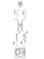
- FIG. 1 is a schematic diagram showing the problem to be solved by the disclosed technology.
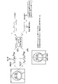
- FIG. 2 is a schematic diagram showing the principle of calculating the pulse rate from an image of the face of a subject not wearing a mask by a conventional pulse wave detection device.
- FIG. 3 is a block diagram showing functional blocks of the pulse wave detection device (100) according to Embodiment 1.
- FIG. 4 is a schematic diagram showing the skin processing steps of the skin region detector (10) of the pulse wave detector (100) according to the first embodiment.
- FIG. 5 is a schematic diagram showing processing steps of the shield detection unit (20) of the pulse wave detection device (100) according to the first embodiment.
- FIG. 6 is a schematic diagram showing processing steps of the measurement region setting unit (30) of the pulse wave detection device (100) according to the first embodiment.
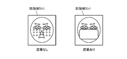
- FIG. 6A is a schematic diagram showing the skin area S(k) before being processed by the measurement area setting unit (30).
- FIG. 6B is a schematic diagram showing the skin area S(k) after being processed by the measurement area setting unit (30).
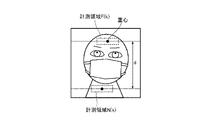
- FIG. 7 is a schematic diagram showing that the phases of the pulse waves are shifted between the forehead and the neck.
- FIG. 8 is a schematic diagram showing the action of the pulse wave estimator (60) of the pulse wave detector (100) according to Embodiment 1.
- FIG. FIG. 9 is a schematic diagram showing the action of the pulse wave estimator (60) of the pulse wave detector (100) according to the second embodiment.
- FIG. 10 is a flow chart showing the flow of the pulse wave detection device (100) according to the technology disclosed herein.
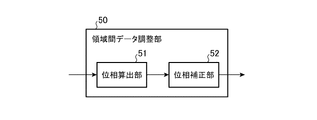
- FIG. 11 is a block diagram showing the configuration of the inter-region data adjustment section (50) of the pulse wave detection device (100) according to Embodiment 3. As shown in FIG.
- FIG. 1 is a schematic diagram showing the problem to be solved by the disclosed technology.
- FIG. 2 is a schematic diagram showing the principle of calculating the pulse rate from an image of the subject's face, which is not masked, by the conventional pulse wave detector.
- the leftmost image in FIG. 2 represents an image of the subject's face without the mask.
- a conventional pulse wave detection device sets a region of interest (the region surrounded by a white square in the figure) from the subject's face image, and selects the left and right cheek regions as samples as a pair of small regions.
- the second block from the left in FIG. 2 is a graph showing the luminance values of the left and right cheek regions selected as samples on the time axis.
- the third block from the left in FIG. 2 represents a block for performing independent component analysis or principal component analysis. This block performs signal processing on the pair of luminance value signals selected as samples to extract a pulse wave component and a noise component.
- the fourth block from the left in FIG. 2 is a graph representing each of the extracted pulse wave component and noise component on the time axis.
- the rightmost block in FIG. 2 represents a block for calculating the pulse rate from the extracted pulse wave component signal.
- FIG. 3 is a block diagram showing functional blocks of pulse wave detecting device 100 according to Embodiment 1.
- the pulse wave detection device 100 includes a skin region detection unit 10, a shielding detection unit 20, a measurement region setting unit 30, a luminance signal extraction unit 40, an inter-region data adjustment unit 50, and a pulse wave estimation unit. a portion 60;
- Pulse wave detection device 100 is also connected to camera 200 .
- Pulse wave detection device 100 may be a vehicle-mounted device, and camera 200 may be a driver monitoring system (hereinafter referred to as "DMS").
- DMS driver monitoring system
- a target whose pulse wave is to be detected is called a "subject", but in the technology disclosed herein, a broader term "subject" is used.
- FIG. 10 is a flowchart showing the flow of pulse wave detection device 100 according to Embodiment 1.
- FIG. 10 is a flowchart showing the flow of pulse wave detection device 100 according to Embodiment 1.
- FIG. 4 is a schematic diagram showing processing steps of the skin region detection unit 10 of the pulse wave detection device 100 according to the first embodiment.
- the image data of the subject imaged by the camera 200 is input to the skin area detection section 10 .
- the skin area detection unit 10 detects a skin area S(k), which is an area including human skin, from the input image data frame Im(k) (step ST10 in FIG. 10).
- k represents a frame number.
- the skin area S(k) is a partial area of the frame Im(k) and may be rectangular, for example. More specifically, the skin area S(k) is an area obtained by trimming the frame Im(k), and is an area in which the exposed skin typified by the face is left. Also, the number of skin regions S(k) does not need to be one, and may be multiple regions.
- the skin area S(k) detected by the skin area detection unit 10 is output to the shielding detection unit 20 .
- FIG. 5 is a schematic diagram showing processing steps of the shield detection unit 20 of the pulse wave detection device 100 according to the first embodiment.
- the shielding detection unit 20 determines whether the target person's skin is shielded by a mask or the like from the output skin region S(k). When it is determined that the subject's skin is shielded, shielding detection section 20 detects shielding position information (step indicated by ST20 in FIG. 10).
- Detecting the shielding position information may use, for example, pattern detection using the Haar-like feature amount or pattern detection using the HOG feature amount.
- the shielding detection unit 20 may refer to the facial feature point information of the unshielded face model and determine that there is shielding around the missing facial feature point.
- the facial organ point information refers to, for example, points having characteristics such as the inner and outer corners of eyes.
- the detected shielding position information is output to the measurement area setting section 30 together with the frame Im(k) and the skin area S(k). where k is a serial number called the frame number.
- FIG. 6 is a schematic diagram showing processing steps of the measurement region setting unit 30 of the pulse wave detection device 100 according to the first embodiment.
- FIG. 6A is a schematic diagram showing the skin area S(k) before being processed by the measurement area setting unit 30.
- FIG. 6B is a schematic diagram showing the skin region S(k) after processing by the measurement region setting unit 30. As shown in FIG.
- the measurement region setting unit 30 sets a measurement region R(k) consisting of a plurality of small regions r i (k) for extracting a pulse wave signal from the skin region S(k) (ST30 in FIG. 10 steps shown).
- the example shown in FIG. 6 shows the case where the cheek region is masked.
- the skin region S(k) is set by the measurement region setting unit 30 as a measurement region consisting of eight small regions each for the forehead portion and the neck portion.
- the measurement area of the forehead is denoted F(k)
- the measurement area of the neck is denoted N(k) so as to distinguish them from each other.
- the eight small areas that constitute the forehead measurement area F(k) are described as f i (k).
- the eight sub-regions forming the neck measurement region N(k) are described as n i (k).
- the subscript i is a serial number assigned to the small area.
- Fig. 6A shows facial organ detection points.
- a mathematical model such as a Constrained Local Model (hereinafter referred to as “CLM”) may be used to detect the coordinate values of facial feature detection points.
- the measurement region setting unit 30 may use tracking technology such as a Kanade-Lucas-Tomasi (hereinafter referred to as “KLT”) tracker.
- KLT Kanade-Lucas-Tomasi
- both CLM and KLT may be used.
- the measurement region setting unit 30 uses CLM to detect the coordinates of facial organ points for the skin region S(1) of the first frame Im(1), and detects the coordinates of the skin region S(1) of the next frame Im(2). 2) You may track a facial feature point by KLT for later.
- CLM may be executed once every several frames for KLTs of the second and subsequent frames.
- FIG. 6B shows an example in which the forehead and neck are set as measurement regions
- the measurement region is not limited to this.
- the portion to be set as the measurement region may be other portions such as the eye area, as long as the skin is exposed.
- FIG. 6B shows an example in which the measurement area is divided into eight small areas, the present invention is not limited to this.
- Information about the measurement area set by the measurement area setting unit 30 and the small areas that constitute the measurement area is output to the luminance signal extraction unit 40 .
- the luminance signal extraction unit 40 calculates a value representing the luminance value of the pixels included in the small region as luminance signal information G i (k).
- the representative value may be, for example, the average luminance value of the pixels included in the small area. Also, the representative value is not limited to the average value, and a variance or the like may be used.
- the luminance signal extraction unit 40 connects the luminance signal information G i (k) for each k in time series to generate a time-series luminance signal.
- the luminance signal extraction unit 40 not only calculates the current k-th luminance signal information G i (k), but also stores the previous k-1-th luminance signal information G i (k-1), A function may be provided to calculate the difference between the kth and the k-1th.
- the time-series time-series luminance signal calculated by the luminance signal extraction unit 40 is output to the inter-region data adjustment unit 50 together with the information of the measurement region from which the time-series luminance signal was obtained.
- the information about the measurement area is, specifically, information about which part of the subject's face the measurement area is.
- the information of the measurement area is information that F(k) is the forehead and information that N(k) is the neck.
- the inter-region data adjustment unit 50 processes a plurality of time-series luminance signals for each small region of each measurement region.
- the operation of the inter-region data adjustment unit 50 according to the first embodiment will be made clear by the following description.
- setting the region of interest as wide as possible is also based on the premise that a certain condition is satisfied.
- the certain condition is that the phases of the pulse waves are aligned within the region of interest. Extracting pulse wave information from an image using independent component analysis or principal component analysis also assumes that the pulse waves are in phase within the region of interest.
- the problem to be solved by the technique of the present disclosure occurs when the phases of the pulse waves do not match within the region of interest. If the phases of the pulse waves do not match within the region of interest, the premise of independent component analysis or principal component analysis may not be satisfied, and pulse wave information may not be extracted correctly.
- FIG. 7 is a schematic diagram showing that the phases of the pulse waves are shifted between the forehead and the neck.
- the phase difference here is sometimes expressed as a delay time appearing on the time axis.
- FIG. 8 is a schematic diagram showing the operation of pulse wave estimating section 60 of pulse wave detecting device 100 according to the first embodiment.
- inter-region data adjusting section 50 according to Embodiment 1 adjusts phases between a plurality of time-series luminance signals based on information on measurement regions (step indicated by ST40 in FIG. 10). .
- the amount of phase to be adjusted that is, the amount of time shift of the time-series luminance signal can be obtained by several methods.
- the simplest method is to determine the amount of time shift so that the peak positions of the time-series luminance signals are aligned.
- the amount of phase to adjust may be determined statistically. More specifically, the inter-region data adjustment unit 50 according to the first embodiment may hold in advance information on the pulse wave phase difference between facial regions.
- the information on the pulse wave phase difference between facial regions may be held according to the features of the subject. For example, phase difference information may be held separately for each gender and each age group.
- the parts of the face may be, for example, the forehead, under the eyes, cheeks, chin, and neck.
- the inter-region data adjustment unit 50 according to Embodiment 1 may adjust phases between a plurality of time-series luminance signals based on measurement region information and prestored phase difference information. A plurality of phase-adjusted time-series luminance signals are output to pulse wave estimating section 60 .
- the pulse wave estimator 60 separates the plurality of phase-adjusted time-series luminance signals into pulse wave components and noise components (step indicated by ST50 in FIG. 10). Independent component analysis or principal component analysis may be used to separate the pulse wave component and the noise component. Pulse wave estimating section 60 estimates the pulse rate from the time-series data of the extracted pulse wave component (step ST60 in FIG. 10).
- pulse wave detection apparatus 100 can detect a pulse wave signal of a subject even from an image of the face of the subject wearing a mask.
- Embodiment 2 In pulse wave detecting device 100 according to Embodiment 1, pulse wave estimating section 60 adjusts phases between a plurality of time-series luminance signals based on information on the measurement region.
- Embodiment 2 has the same configuration as that shown in Embodiment 1, but pulse wave estimating section 60 operates differently from Embodiment 1, and solves the problem of the disclosed technique.
- the same reference numerals as those used in the first embodiment are used unless otherwise specified. Further, in the second embodiment, explanations overlapping those of the first embodiment are omitted as appropriate.
- FIG. 9 is a schematic diagram showing the operation of pulse wave estimating section 60 of pulse wave detecting device 100 according to the second embodiment.
- the inter-region data adjustment unit 50 according to Embodiment 2 groups the time-series luminance signals for the small regions for each measurement region.
- the inter-region data adjustment unit 50 according to the second embodiment separately performs pulse wave estimation based on luminance information in which the measurement region is the forehead and pulse wave estimation based on luminance information in which the measurement region is the neck.
- the pulse wave estimating unit 60 is instructed to perform each step separately.
- Pulse wave estimating section 60 instructed to perform pulse wave estimation for each measurement region, that is, for each region of the face, separates the time-series luminance signal into a pulse wave component and a noise component for each measurement region (ST50 in FIG. 10). step indicated by ).
- the pulse wave estimator 60 separates the time-series luminance signal for the forehead into a pulse wave component and a noise component, and separates the time-series luminance signal for the neck into a pulse wave component and a noise component. To separate.
- the pulse wave estimator 60 estimates the pulse rate for each measurement region from the time-series data of the pulse wave component extracted for each measurement region.
- the pulse wave estimator 60 according to Embodiment 2 calculates a plausible pulse rate from the pulse rate estimated for each measurement region.
- a weighted average process for example, may be used to calculate the plausible pulse rate.
- the reliability may be used as the weight used in the weighted averaging process.
- the S/N ratio of the time-series luminance signal obtained for each measurement region may be used as the reliability.
- the pulse wave estimating unit 60 calculates a plausible pulse rate using weighted averaging of the pulse rate itself, but is not limited to this.
- a pulse wave estimator 60 performs weighted averaging on the luminance signal or pulse wave component signal in the measurement region, calculates a likely luminance signal or pulse wave component signal, and calculates a likely luminance signal or pulse wave component signal from the Pulse rate may be calculated.
- the pulse wave detection device 100 according to Embodiment 2 since the pulse wave detection device 100 according to Embodiment 2 has the above configuration, even if the subject wears a mask, the phase effects between the plurality of time-series luminance signals of the region of interest are eliminated. be done. Due to the effect of eliminating this phase effect, the pulse wave detection device 100 according to Embodiment 2 can detect the subject's pulse wave signal even from an image of the subject's face wearing a mask.
- inter-region data adjusting section 50 of pulse wave detecting device 100 is configured with two functional blocks.
- the same reference numerals as those used in the previous embodiments are used unless otherwise specified. Further, in the third embodiment, explanations overlapping those of the previous embodiments are omitted as appropriate.
- FIG. 11 is a block diagram showing the configuration of the inter-region data adjustment unit (50) of the pulse wave detection device (100) according to the third embodiment.
- the inter-region data adjustment unit (50) according to the third embodiment includes a phase calculation unit 51 and a phase correction unit 52.
- FIG. 11 is a block diagram showing the configuration of the inter-region data adjustment unit (50) of the pulse wave detection device (100) according to the third embodiment.
- the inter-region data adjustment unit (50) according to the third embodiment includes a phase calculation unit 51 and a phase correction unit 52.
- the phase calculator 51 of the inter-region data adjuster 50 calculates the phase difference between the plurality of time-series luminance signals based on the information of the measurement regions.
- the phase difference is the delay time appearing on the time axis.
- the phase difference may be obtained so that the peak positions of the two time-series luminance signals are aligned.
- the phase difference may be changed using the phase as a parameter, and the solution may be the one that minimizes the integrated value of the squared error of the two time-series luminance signals.
- the phase correction unit 52 of the inter-region data adjustment unit 50 uses the phase difference obtained by the phase calculation unit 51 to correct the phases between the plurality of time-series luminance signals.
- the pulse wave detecting device 100 according to Embodiment 3 has the above configuration, and phases between a plurality of time-series luminance signals of the region of interest are corrected even when the subject wears a mask. With this phase-correcting action, the pulse wave detection device 100 according to the third embodiment can detect the pulse wave signal of the subject even from an image of the face of the subject wearing a mask.
- the disclosed technology can be applied to in-vehicle equipment such as DMS, and has industrial applicability.
- Skin region detection unit 20 Shielding detection unit 30 Measurement region setting unit 40 Luminance signal extraction unit 50 Inter-region data adjustment unit 51 Phase calculation unit 52 Phase correction unit 60 Pulse wave estimation unit 100 Pulse wave detection Device, 200 camera.
Landscapes
- Health & Medical Sciences (AREA)
- Life Sciences & Earth Sciences (AREA)
- Engineering & Computer Science (AREA)
- Surgery (AREA)
- General Health & Medical Sciences (AREA)
- Biophysics (AREA)
- Pathology (AREA)
- Veterinary Medicine (AREA)
- Biomedical Technology (AREA)
- Heart & Thoracic Surgery (AREA)
- Medical Informatics (AREA)
- Molecular Biology (AREA)
- Public Health (AREA)
- Animal Behavior & Ethology (AREA)
- Physics & Mathematics (AREA)
- Physiology (AREA)
- Cardiology (AREA)
- Signal Processing (AREA)
- Nuclear Medicine, Radiotherapy & Molecular Imaging (AREA)
- Radiology & Medical Imaging (AREA)
- Artificial Intelligence (AREA)
- Computer Vision & Pattern Recognition (AREA)
- Psychiatry (AREA)
- Computer Networks & Wireless Communication (AREA)
- Measuring Pulse, Heart Rate, Blood Pressure Or Blood Flow (AREA)
Abstract
Description
さらに例えば特許文献1には、被験者の顔が動いても、顔に当たる光が変化しても、精確に計測できる技術が開示されている。
図2の左から2番目のブロックは、サンプルとして選択された左右の頬領域の輝度値を時間軸で表したグラフである。
図2の左から3番目のブロックは、独立成分分析又は主成分分析を行うブロックを表す。ここのブロックは、サンプルとして選択した対の輝度値の信号に対して信号処理を行い、脈波成分とノイズ成分とを抽出する。
図2の左から4番目のブロックは、抽出された脈波成分とノイズ成分とのそれぞれを時間軸で表したグラフである。
図2の一番右のブロックは、抽出された脈波成分の信号から脈拍数を算出するブロックを表している。
図3は、実施の形態1に係る脈波検出装置100の機能ブロックを示したブロック図である。図3が示すとおり脈波検出装置100は、肌領域検出部10と、遮蔽検知部20と、計測領域設定部30と、輝度信号抽出部40と、領域間データ調整部50と、脈波推定部60と、を含む。また、脈波検出装置100は、カメラ200と接続されている。
脈波検出装置100は車載器であってもよく、またカメラ200はドライバモニタリングシステム(以下、「DMS」と称する)であってもよい。従来技術において脈波を検出する対象を「被験者」と称していたが、本開示技術ではより広い「対象者」という表現が用いられる。
検出された遮蔽位置情報は、フレームIm(k)と肌領域S(k)とともに、計測領域設定部30へ出力される。ここでkは、フレーム番号と称する通し番号である。
また図6Bには計測領域を8つの小領域に分割した例が示されているが、これに限定されない。
このことを本開示技術に当てはめると、脈波情報抽出を、計測領域設定部30で設定されたすべての計測領域を関心領域と設定して行うことが望ましい。すなわち領域間データ調整部50は、送られたすべての時系列輝度信号を平均化し、脈波情報抽出することが望ましい。
本開示技術が解決しようとする課題は、関心領域内において脈波の位相がそろわない場合に生じる。関心領域内において脈波の位相がそろわないことは、独立成分分析又は主成分分析の前提が満たされず、脈波情報が正しく抽出されないおそれがある。
昨今では、対象者がマスクをしている状況が増えている。マスクは前述のとおり、関心領域を限定し、例えば額と首とが選ばれる。額と首とでは、心臓から血液が経由した経路の距離が異なるため、脈波の位相はずれている。図7は、額と首とでは、脈波の位相がずれることを示した模式図である。ここでの位相差は、時間軸上に現れる遅れ時間と表現されることもある。
位相が調整された複数の時系列輝度信号は、脈波推定部60へ出力される。
実施の形態1に係る脈波検出装置100は、脈波推定部60が計測領域の情報に基づいて、複数の時系列輝度信号の間の位相を調整するものである。実施の形態2は、実施の形態1で示したものと同じ構成だが、脈波推定部60が実施の形態1とは異なる作用をし、本開示技術の課題を解決するものである。
実施の形態2は、特に明記する場合を除き実施の形態1で用いたものと同じ符号が用いられる。また実施の形態2では、実施の形態1と重複する説明は適宜省略される。
図9で示されているように脈波推定部60は、脈拍数自体に重み付き平均処理を用いてもっともらしい脈拍数を算出しているが、これに限定されない。脈波推定部60は、計測領域の輝度信号又は脈波成分信号に対して重み付き平均処理を行い、もっともらしい輝度信号又は脈波成分信号を算出し、もっともらしい輝度信号又は脈波成分信号から脈拍数を算出してもよい。
実施の形態3は、実施の形態1に係る脈波検出装置100の領域間データ調整部50を、2つの機能ブロックで構成したものである。
実施の形態3は、特に明記する場合を除き既出の実施の形態で用いたものと同じ符号が用いられる。また実施の形態3では、既出の実施の形態と重複する説明は適宜省略される。
ここで位相差は、2つの時系列輝度信号のピークの位置が合うように求められてもよい。また位相差は、位相をパラメータとして変化させ、2つの時系列輝度信号の二乗誤差の積分値が最小となるものを解としてよい。
Claims (4)
- 対象者を撮像した画像から脈波を検出する脈波検出装置であって、
位相算出部と位相補正部とを有する領域間データ調整部を含み、
前記位相算出部は、前記画像の関心領域の複数の時系列輝度信号の間の位相差を算出し、
前記位相補正部は、算出された前記位相差に基づいて、前記時系列輝度信号の位相を補正することを特徴とする脈波検出装置。 - 前記位相算出部は、前記関心領域の計測領域ごとの前記時系列輝度信号のピークの位置に基づいて位相を算出する請求項1に記載の脈波検出装置。
- 前記位相算出部は、2つの前記時系列輝度信号の二乗誤差の積分値に基づいて位相を算出する請求項1に記載の脈波検出装置。
- 対象者を撮像した画像から脈波を検出する脈波検出方法であって、
前記画像の関心領域の複数の時系列輝度信号の間の位相差を算出し、
算出された前記位相差に基づいて、前記時系列輝度信号の位相を補正することを含む脈波検出方法。
Priority Applications (4)
| Application Number | Priority Date | Filing Date | Title |
|---|---|---|---|
| JP2023508382A JP7561966B2 (ja) | 2021-03-26 | 2021-03-26 | 脈波検出装置及び脈波検出方法 |
| DE112021007383.4T DE112021007383T5 (de) | 2021-03-26 | 2021-03-26 | Pulswellenerkennungsvorrichtung undpulswellenerkennungsverfahren |
| US18/281,958 US20240298906A1 (en) | 2021-03-26 | 2021-03-26 | Pulse wave detector |
| PCT/JP2021/012915 WO2022201507A1 (ja) | 2021-03-26 | 2021-03-26 | 脈波検出装置及び脈波検出方法 |
Applications Claiming Priority (1)
| Application Number | Priority Date | Filing Date | Title |
|---|---|---|---|
| PCT/JP2021/012915 WO2022201507A1 (ja) | 2021-03-26 | 2021-03-26 | 脈波検出装置及び脈波検出方法 |
Publications (1)
| Publication Number | Publication Date |
|---|---|
| WO2022201507A1 true WO2022201507A1 (ja) | 2022-09-29 |
Family
ID=83396528
Family Applications (1)
| Application Number | Title | Priority Date | Filing Date |
|---|---|---|---|
| PCT/JP2021/012915 Ceased WO2022201507A1 (ja) | 2021-03-26 | 2021-03-26 | 脈波検出装置及び脈波検出方法 |
Country Status (4)
| Country | Link |
|---|---|
| US (1) | US20240298906A1 (ja) |
| JP (1) | JP7561966B2 (ja) |
| DE (1) | DE112021007383T5 (ja) |
| WO (1) | WO2022201507A1 (ja) |
Cited By (2)
| Publication number | Priority date | Publication date | Assignee | Title |
|---|---|---|---|---|
| IT202200026922A1 (it) | 2022-12-28 | 2024-06-28 | Ima Spa | Apparecchiatura e procedimento per movimentare automaticamente oggetti nell’ambito di un ambiente con atmosfera controllata. |
| IT202200026916A1 (it) | 2022-12-28 | 2024-06-28 | Ima Spa | Apparecchiatura e procedimento per chiudere automaticamente contenitori. |
Citations (3)
| Publication number | Priority date | Publication date | Assignee | Title |
|---|---|---|---|---|
| JP2014073159A (ja) * | 2012-10-02 | 2014-04-24 | Fujitsu Ltd | 脈波検出装置、脈波検出プログラム及び脈波検出方法 |
| JP2017093830A (ja) * | 2015-11-25 | 2017-06-01 | 日本電信電話株式会社 | 同一性判定システム、顔脈波測定装置、及び同一性判定方法 |
| JP2020010772A (ja) * | 2018-07-13 | 2020-01-23 | 美津濃株式会社 | 脈拍検出方法、および、脈拍検出システム |
Family Cites Families (1)
| Publication number | Priority date | Publication date | Assignee | Title |
|---|---|---|---|---|
| JP6521845B2 (ja) | 2015-11-22 | 2019-05-29 | 国立大学法人埼玉大学 | 心拍に連動する周期的変動の計測装置及び計測方法 |
-
2021
- 2021-03-26 US US18/281,958 patent/US20240298906A1/en not_active Abandoned
- 2021-03-26 JP JP2023508382A patent/JP7561966B2/ja active Active
- 2021-03-26 WO PCT/JP2021/012915 patent/WO2022201507A1/ja not_active Ceased
- 2021-03-26 DE DE112021007383.4T patent/DE112021007383T5/de active Pending
Patent Citations (3)
| Publication number | Priority date | Publication date | Assignee | Title |
|---|---|---|---|---|
| JP2014073159A (ja) * | 2012-10-02 | 2014-04-24 | Fujitsu Ltd | 脈波検出装置、脈波検出プログラム及び脈波検出方法 |
| JP2017093830A (ja) * | 2015-11-25 | 2017-06-01 | 日本電信電話株式会社 | 同一性判定システム、顔脈波測定装置、及び同一性判定方法 |
| JP2020010772A (ja) * | 2018-07-13 | 2020-01-23 | 美津濃株式会社 | 脈拍検出方法、および、脈拍検出システム |
Cited By (2)
| Publication number | Priority date | Publication date | Assignee | Title |
|---|---|---|---|---|
| IT202200026922A1 (it) | 2022-12-28 | 2024-06-28 | Ima Spa | Apparecchiatura e procedimento per movimentare automaticamente oggetti nell’ambito di un ambiente con atmosfera controllata. |
| IT202200026916A1 (it) | 2022-12-28 | 2024-06-28 | Ima Spa | Apparecchiatura e procedimento per chiudere automaticamente contenitori. |
Also Published As
| Publication number | Publication date |
|---|---|
| DE112021007383T5 (de) | 2024-01-04 |
| US20240298906A1 (en) | 2024-09-12 |
| JP7561966B2 (ja) | 2024-10-04 |
| JPWO2022201507A1 (ja) | 2022-09-29 |
Similar Documents
| Publication | Publication Date | Title |
|---|---|---|
| US8811657B2 (en) | Method and apparatus for image-based eye tracking for retinal diagnostic or surgery device | |
| US11547309B2 (en) | Biological information detection device, biological information detection method and non-transitory computer-readable storage medium for biological information detection | |
| US10478079B2 (en) | Pulse estimation device, pulse estimation system, and pulse estimation method | |
| US20130322729A1 (en) | Processing a video for vascular pattern detection and cardiac function analysis | |
| US20180307927A1 (en) | In-Vehicle Monitoring | |
| EP3378387B1 (en) | Heart rate estimation from face videos using quality based fusion | |
| CN109700449B (zh) | 一种可抗头部自然运动的有效心率量测系统 | |
| JP7131709B2 (ja) | 推定装置、方法及びプログラム | |
| CN111127511B (zh) | 一种非接触式心率监测方法 | |
| WO2022201507A1 (ja) | 脈波検出装置及び脈波検出方法 | |
| CN110781712B (zh) | 一种基于人脸检测与识别的人头空间定位方法 | |
| CN111513701A (zh) | 心率检测方法、装置、计算机设备和可读存储介质 | |
| US20250252562A1 (en) | Method for estimating heart rate on basis of corrected image, and device therefor | |
| WO2022201505A1 (ja) | 脈波検出装置及び脈波検出方法 | |
| US10779771B2 (en) | Signal processing method and apparatus | |
| JP7514521B2 (ja) | 心拍測定システム、心拍測定方法、及び心拍測定プログラム | |
| JPWO2022201505A5 (ja) | ||
| CN111524167A (zh) | 一种移动放射源定位校正与优化方法 | |
| CN117547238A (zh) | 一种在复杂条件下进行视频心率检测方法及检测系统 | |
| CN119924891B (zh) | 一种二维斑点追踪联合组织多普勒的osas心脏力学分析系统 | |
| CN121053240B (zh) | 一种x射线探测器阵列成像系统 | |
| CN119074023B (zh) | 一种自适应运动轨迹智能图像采集方法 | |
| CN115497151B (zh) | 应用于电视场景的检测特定年龄段不良姿势的方法 | |
| Sharma et al. | A real-time framework to find optimal roi for contactless heart rate variability detection | |
| Sobotka et al. | Evaluation of Skin Segmentation Methods for Explainable Pulse Signal Analysis |
Legal Events
| Date | Code | Title | Description |
|---|---|---|---|
| 121 | Ep: the epo has been informed by wipo that ep was designated in this application |
Ref document number: 21933112 Country of ref document: EP Kind code of ref document: A1 |
|
| ENP | Entry into the national phase |
Ref document number: 2023508382 Country of ref document: JP Kind code of ref document: A |
|
| WWE | Wipo information: entry into national phase |
Ref document number: 18281958 Country of ref document: US |
|
| WWE | Wipo information: entry into national phase |
Ref document number: 112021007383 Country of ref document: DE |
|
| 122 | Ep: pct application non-entry in european phase |
Ref document number: 21933112 Country of ref document: EP Kind code of ref document: A1 |