WO2022201425A1 - 情報処理装置、隠れノードの設定方法及び情報処理装置の製造方法 - Google Patents
情報処理装置、隠れノードの設定方法及び情報処理装置の製造方法 Download PDFInfo
- Publication number
- WO2022201425A1 WO2022201425A1 PCT/JP2021/012533 JP2021012533W WO2022201425A1 WO 2022201425 A1 WO2022201425 A1 WO 2022201425A1 JP 2021012533 W JP2021012533 W JP 2021012533W WO 2022201425 A1 WO2022201425 A1 WO 2022201425A1
- Authority
- WO
- WIPO (PCT)
- Prior art keywords
- layer
- reservoir layer
- nodes
- information processing
- processing device
- Prior art date
- Legal status (The legal status is an assumption and is not a legal conclusion. Google has not performed a legal analysis and makes no representation as to the accuracy of the status listed.)
- Ceased
Links
Images








Classifications
-
- G—PHYSICS
- G06—COMPUTING OR CALCULATING; COUNTING
- G06N—COMPUTING ARRANGEMENTS BASED ON SPECIFIC COMPUTATIONAL MODELS
- G06N3/00—Computing arrangements based on biological models
- G06N3/02—Neural networks
- G06N3/08—Learning methods
-
- G—PHYSICS
- G06—COMPUTING OR CALCULATING; COUNTING
- G06N—COMPUTING ARRANGEMENTS BASED ON SPECIFIC COMPUTATIONAL MODELS
- G06N3/00—Computing arrangements based on biological models
- G06N3/02—Neural networks
- G06N3/06—Physical realisation, i.e. hardware implementation of neural networks, neurons or parts of neurons
- G06N3/063—Physical realisation, i.e. hardware implementation of neural networks, neurons or parts of neurons using electronic means
- G06N3/065—Analogue means
-
- G—PHYSICS
- G06—COMPUTING OR CALCULATING; COUNTING
- G06N—COMPUTING ARRANGEMENTS BASED ON SPECIFIC COMPUTATIONAL MODELS
- G06N3/00—Computing arrangements based on biological models
- G06N3/02—Neural networks
- G06N3/04—Architecture, e.g. interconnection topology
-
- G—PHYSICS
- G06—COMPUTING OR CALCULATING; COUNTING
- G06N—COMPUTING ARRANGEMENTS BASED ON SPECIFIC COMPUTATIONAL MODELS
- G06N3/00—Computing arrangements based on biological models
- G06N3/02—Neural networks
- G06N3/04—Architecture, e.g. interconnection topology
- G06N3/044—Recurrent networks, e.g. Hopfield networks
-
- G—PHYSICS
- G06—COMPUTING OR CALCULATING; COUNTING
- G06N—COMPUTING ARRANGEMENTS BASED ON SPECIFIC COMPUTATIONAL MODELS
- G06N3/00—Computing arrangements based on biological models
- G06N3/02—Neural networks
- G06N3/04—Architecture, e.g. interconnection topology
- G06N3/045—Combinations of networks
- G06N3/0455—Auto-encoder networks; Encoder-decoder networks
-
- G—PHYSICS
- G06—COMPUTING OR CALCULATING; COUNTING
- G06N—COMPUTING ARRANGEMENTS BASED ON SPECIFIC COMPUTATIONAL MODELS
- G06N3/00—Computing arrangements based on biological models
- G06N3/02—Neural networks
- G06N3/04—Architecture, e.g. interconnection topology
- G06N3/0495—Quantised networks; Sparse networks; Compressed networks
-
- G—PHYSICS
- G06—COMPUTING OR CALCULATING; COUNTING
- G06N—COMPUTING ARRANGEMENTS BASED ON SPECIFIC COMPUTATIONAL MODELS
- G06N3/00—Computing arrangements based on biological models
- G06N3/02—Neural networks
- G06N3/06—Physical realisation, i.e. hardware implementation of neural networks, neurons or parts of neurons
-
- G—PHYSICS
- G06—COMPUTING OR CALCULATING; COUNTING
- G06N—COMPUTING ARRANGEMENTS BASED ON SPECIFIC COMPUTATIONAL MODELS
- G06N3/00—Computing arrangements based on biological models
- G06N3/02—Neural networks
- G06N3/06—Physical realisation, i.e. hardware implementation of neural networks, neurons or parts of neurons
- G06N3/063—Physical realisation, i.e. hardware implementation of neural networks, neurons or parts of neurons using electronic means
-
- G—PHYSICS
- G06—COMPUTING OR CALCULATING; COUNTING
- G06N—COMPUTING ARRANGEMENTS BASED ON SPECIFIC COMPUTATIONAL MODELS
- G06N3/00—Computing arrangements based on biological models
- G06N3/02—Neural networks
- G06N3/08—Learning methods
- G06N3/082—Learning methods modifying the architecture, e.g. adding, deleting or silencing nodes or connections
-
- G—PHYSICS
- G06—COMPUTING OR CALCULATING; COUNTING
- G06N—COMPUTING ARRANGEMENTS BASED ON SPECIFIC COMPUTATIONAL MODELS
- G06N3/00—Computing arrangements based on biological models
- G06N3/02—Neural networks
- G06N3/08—Learning methods
- G06N3/09—Supervised learning
Definitions
- the present invention relates to an information processing device, a hidden node setting method, and an information processing device manufacturing method.
- a neuromorphic device is an element that mimics the human brain with a neural network. Neuromorphic devices artificially mimic the relationships between neurons and synapses in the human brain.
- a neuromorphic device has, for example, hierarchically arranged nodes (neurons in the brain) and means of communication (synapses in the brain) that connect these nodes.
- Neuromorphic devices increase the rate of correct answers to questions by learning through the means of communication (synapses). Learning is to find knowledge that can be used in the future from information, and the neuromorphic device weights the input data.
- a recurrent neural network is known as one of the neural networks.
- a recurrent neural network can handle time-series data by including recursive connections inside.
- Time-series data is data whose values change with the passage of time, and stock prices are an example thereof.
- a recurrent neural network can also have nonlinear activations inside, in which case the processing in the activations can be mathematically regarded as projection onto a nonlinear multidimensional space. This makes it possible to extract features of complex signal changes that time-series signals have.
- a recursive structure can be realized by returning the processing result of the neuron in the lower layer to the neuron in the upper layer, thereby processing time-series data.
- Reservoir computing is a type of recurrent neural network that includes recursive connections and nonlinear activation functions.
- Reservoir computing is a neural network developed as a method of implementing liquid state machines.
- Reservoir computing is roughly divided into a reservoir layer and a lead-out layer.
- the "layer” here is a conceptual layer, and does not need to be formed as a physical structure.
- a reservoir layer forms a graph structure containing a large number of nonlinear nodes and recursive connections between nodes.
- the readout layer is often composed of a single layer perceptron.
- the reservoir layer mimics the neuron connections of the human brain and expresses states as transitions between interference states.
- a feature of reservoir computing is that the reservoir layer is not the object of learning, and only the lead-out layer is learned.
- Reservoir computing is attracting attention as a system that handles time-series signals at the IoT (Internet of Things) and edges, where hardware resources are limited due to the lack of computer resources required for learning.
- IoT Internet of Things
- Non-Patent Document 1 describes a reservoir element using spin waves as an example of physical device research.
- the present invention has been made in view of the above circumstances, and provides an information processing device suitable for practical use, a hidden node setting method, and an information processing device manufacturing method.
- An information processing apparatus includes a reservoir layer and a lead-out layer, and the reservoir layer includes a plurality of a node, wherein the lead-out layer operates to apply a connection weight to each of the signals sent from the reservoir layer, the number of signals sent from the reservoir layer to the lead-out layer being equal to the number of the signals sent from the plurality of nodes; less than a number
- the information processing device may further include a connection section that connects the reservoir layer and the lead-out layer.
- the connecting portion comprises a plurality of terminals connecting any one of the plurality of nodes to the lead-out layer, and the number of the plurality of terminals is less than the number of the plurality of nodes.
- connection section may include a plurality of wirings.
- Each of the plurality of wirings connects one of the plurality of nodes and one of the plurality of terminals.
- connection unit may include a switch.
- the switch switches electrical connections between the plurality of nodes and the plurality of terminals.
- the connecting portion may be laminated on the reservoir layer.
- the connecting portion includes a plurality of wiring layers.
- the connecting portion may be laminated on the reservoir layer, and the connecting portion may cover a part of the reservoir layer when viewed from the lamination direction.
- the reservoir layer includes a first pad connected to one of the plurality of nodes, and the connecting portion is connected to one of the plurality of terminals.
- the connecting portion may be bonded to the reservoir layer via the first pad and the second pad.
- the plurality of nodes may include hidden nodes that are not connected to the lead-out layer.
- the hidden node is obtained by statistically analyzing the amount of variation of a plurality of nodes included in the reference information processing device in calculations using the reference information processing device. may be determined based on
- the reference information processing device includes a reference reservoir layer having the same configuration as the reservoir layer, and a reference lead-out layer having the same configuration as the lead-out layer, and the reference reservoir layer is input to the reference reservoir layer. Generating a feature space containing the information of the input signal, the reference readout layer performs operations that apply connection weights to the signals coming from each node of the reference reservoir layer.
- the hidden node may be determined by the absolute value of the weight of the connection between each of the plurality of nodes included in the reference information processing device and the reference readout layer.
- connection weights between the plurality of nodes of the reference reservoir layer and the reference readout layer may be determined by learning including a norm minimization method.
- the information processing apparatus includes a reservoir layer and a lead-out layer, and the reservoir layer includes a plurality of a node, wherein the lead-out layer performs an operation of applying a coupling weight to each signal sent from the reservoir layer, and the number of input terminals to which the input signal is input is less than the number of the plurality of nodes; .
- a method for setting hidden nodes includes a first step of conducting preliminary examination and a second step of determining hidden nodes, wherein the first step comprises a reference reservoir layer; a reference lead-out layer, said reference information processor generating a feature space containing information of an input signal in said reference reservoir layer, and generating a feature space containing information of an input signal in said reference reservoir layer; applying a coupling weight to the signal sent to the reference readout layer from the reference readout layer, and performing a calculation to increase the mutual information between the input value and the ideal value; Based on the connection weight between each node in the reservoir layer or the connection weight between each node in the reference reservoir layer and the reference readout layer, which one of the plurality of nodes included in the reference reservoir layer is selected as the Determines if it can be a hidden node.
- a method for manufacturing an information processing device includes the steps of designing a reservoir layer and a lead-out layer connectable to the reservoir layer, and using a reference reservoir layer having the same configuration as the reservoir layer. performing the hidden node setting method according to the above aspect, setting a hidden node in the reservoir layer; and connecting a node other than the hidden node among a plurality of nodes included in the reservoir layer to the lead-out layer.
- the information processing device, hidden node setting method, and information processing device manufacturing method according to the above aspects are suitable for practical use.
- FIG. 1 is a conceptual diagram of an information processing apparatus according to a first embodiment
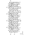
- FIG. 1 is a cross-sectional view of part of an information processing apparatus according to a first embodiment
- FIG. 1 is a conceptual diagram of a reference information processing device according to a first embodiment
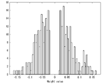
- FIG. Fig. 3 shows the distribution of connection weights between each node and the lead-out layer in the reference information processor
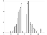
- 4 shows distribution of connection weights between each node and a lead-out layer in the information processing apparatus according to the first embodiment
- FIG. 1 is a conceptual diagram of an information processing apparatus according to a first embodiment
- FIG. 1 is a cross-sectional view of part of an information processing apparatus according to a first embodiment
- FIG. 1 is a conceptual diagram of a reference information processing device according to a first embodiment
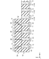
- FIG. 11 is a cross-sectional view of part of an information processing apparatus according to a first modified example
- FIG. 11 is a cross-sectional view of part of an information processing apparatus according to a second modified example
- FIG. 11 is a cross-sectional view of part of an information processing apparatus according to a third modified example
- FIG. 11 is a cross-sectional view of part of an information processing apparatus according to a fourth modified example
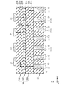
- FIG. 14 is a cross-sectional view of part of an information processing apparatus according to a fifth modified example;
- FIG. 1 is a conceptual diagram of an information processing device 100 according to the first embodiment.
- the information processing device 100 includes, for example, a reservoir layer 10, a lead-out layer 20, and a connection section 30.
- a “layer” may represent a “layer” as a physical structure or a "layer” as a concept.
- layer means a conceptual layer
- FIGS. 2 and 10 to 14 described later “layer” means a layer as a structure. .
- the reservoir layer 10 includes multiple nodes 11 .
- the number of nodes 11 is not particularly limited. The greater the number of nodes 11, the more expressive the reservoir layer 10 is. For example, let the number of nodes 11 be i. i is any natural number.
- Each of the nodes 11 is replaced with, for example, a physical device.
- a physical device is, for example, a device that can convert an input signal into vibration, an electromagnetic field, a magnetic field, a spin wave, or the like.
- Node 11 is, for example, a MEMS microphone.
- a MEMS microphone can convert the vibration of a vibrating membrane into an electrical signal.
- Node 11 may be, for example, a Spin Torque Oscillator (STO).
- STO Spin Torque Oscillator
- a spin torque oscillator can convert an electrical signal into a high frequency signal.
- connection weight vx is defined between each node 11, for example.
- the number of defined connection weights v x is equal to the number of combinations of connections between nodes 11 .
- x is, for example, any natural number.
- Each of the connection weights vx between nodes 11 is defined in principle, and does not change due to learning.
- Each of the connection weights v x between nodes 11 is arbitrary and may be identical or different. Some of the connection weights vx between multiple nodes 11 may vary due to learning.
- a signal S in is input to the reservoir layer 10 .
- the signal S in is input from, for example, a sensor provided outside.
- Signal S in interacts as it propagates between multiple nodes 11 within reservoir layer 10 .
- the signal S in interacting means that a signal propagating to a certain node 11 affects a signal propagating to another node 11 .
- the coupling weight v x is applied and changes.
- the reservoir layer 10 projects the input signal S in to a multidimensional nonlinear space.
- the plurality of nodes 11 As the signal S in propagates between the plurality of nodes 11 , the plurality of nodes 11 generate a feature space containing the information of the signal S in input to the reservoir layer 10 .
- the input signal S_in is replaced by another signal and at least part of the information contained in the input signal S_in is retained in a modified form.
- the input signal S in varies non-linearly within the reservoir layer 10 .
- An example of such conversion is the replacement from the orthogonal coordinate system (x, y, z) to the spherical coordinate system (r, ⁇ , ⁇ ).
- the interaction of the input signal S in within the reservoir layer 10 changes the state of the system of the reservoir layer 10 over time.
- Some of the plurality of nodes 11 are connected to the lead-out layer 20 via the connection section 30.
- i nodes 11, j (j is any natural number smaller than i) nodes 11 are connected to the lead-out layer 20.
- FIG. The remaining ij nodes 11 contribute to signal interactions within the reservoir layer 10 but are not connected to the leadout layer 20 .
- Nodes 11 that are not connected to the lead-out layer 20 are hereinafter referred to as hidden nodes.
- the connecting part 30 is, for example, between the reservoir layer 10 and the lead-out layer 20 .
- FIG. 2 is a cross-sectional view of the reservoir layer 10 and the connecting portion 30 according to the first embodiment.
- the stacking direction of each layer will be referred to as the z-direction
- one direction perpendicular to the z-direction will be referred to as the x-direction
- the z-direction and the direction perpendicular to the x-direction will be referred to as the y-direction.
- the reservoir layer 10 includes multiple nodes 11 , an insulating layer 12 and multiple terminals 13 .
- Each of the terminals 13 is connected to each of the nodes 11 .
- a terminal 13 is connected to an external sensor and receives a signal S in from the sensor.
- the node 11 itself may function as a sensor whose state changes depending on the external environment.
- an array of piezoelectric elements may itself function and interact with a tactile sensor. That is, the node 11 has both a function as a sensor and a function as a node in reservoir computing.
- the connecting part 30 connects the reservoir layer 10 and the lead-out layer 20 .
- the connection part 30 is laminated on the reservoir layer 10, for example.
- the connecting part 30 covers the reservoir layer 10, for example, when viewed from the z-direction.
- the connecting portion 30 has, for example, a plurality of wirings 31, an insulating layer 32, and a plurality of terminals 34. As shown in FIG.
- the lead-out layer 20 is connected to each of the terminals 34 .
- the wiring 31 has conductivity and is made of Al, Ag, Cu, or the like, for example.
- the insulating layer 32 is an interlayer insulating layer, and includes, for example, silicon oxide (SiO x ), silicon nitride (SiN x ), silicon carbide (SiC), chromium nitride, silicon carbonitride (SiCN), silicon oxynitride (SiON), Aluminum oxide (Al 2 O 3 ), zirconium oxide (ZrO x ), and the like.
- Each of the wirings 31 connects one of the nodes 11 and one of the terminals 34 .
- a first end of the wiring 31 is connected to one of the nodes 11 .
- a second end of the wiring 31 is connected to one of the terminals 34 .
- the number of terminals 34 is j, for example. Each of the terminals 34 is connected to the leadout layer 20 . The number of terminals 34 matches the number of signals sent to leadout layer 20 . The number of terminals 34 (j) is less than the number of nodes 11 (i). The node 11 that is not connected to the terminal 34 among the nodes 11 is the hidden node 11A.
- a signal is sent from the reservoir layer 10 to the lead-out layer 20 .
- the number of signals sent from reservoir layer 10 to lead-out layer 20 (j) is less than the number of nodes 11 in reservoir layer 10 (i).
- the readout layer 20 has, for example, a sum-of-products operation circuit, an activation function circuit, a comparison circuit, and an output circuit.
- the sum-of-products operation circuit multiplies each signal sent from the reservoir layer 10 to the readout layer 20 by the connection weight wj , and sums the multiplied results.
- a coupling weight wj is defined between each of the terminals 34 and the leadout layer 20 .
- the connection weight wj fluctuates by learning.
- the activation function circuit substitutes the sum-of-products operation result for the activation function f(x) and performs the operation.
- An activation function may not be used.
- the comparison circuit compares the calculation result with the teacher data t.
- the comparison circuit compares, for example, the difference in mutual information between the calculation result and the teacher data t.
- Mutual information is a quantity that represents a measure of the interdependence of two random variables.
- the comparison circuit feeds back the data Df to the sum-of-products operation circuit so as to increase (maximize) the mutual information.
- the coupling weight wj between each of the terminals 34 and the leadout layer 20 varies based on the fed back data Df.
- the connection weight wj between each of the terminals 34 and the lead-out layer 20 is adjusted so that the mutual information between the operation result and the teacher data t is increased (maximized). Note that the above calculation is performed in advance, and the weight obtained as a result is reflected in the connection weight between the lead-out layer and the reservoir layer. You don't have to have a vessel.
- the output circuit outputs the operation result to the outside as a signal S out .
- the output circuit is represented by one output signal line in FIG. 1, the present invention is not limited to this case. For example, it is possible to deal with a multi-class classification problem, which is a general application of machine learning. In that case, the output circuit has a plurality of output signal lines corresponding to each class.
- the reservoir layer 10 and the leadout layer 20 are designed. Known layers can be used for the reservoir layer 10 and the lead-out layer 20, respectively. A physical device that configures the node 11 is not particularly limited. The reservoir layer 10 and the lead-out layer 20 can be designed according to the tasks given to the information processing device 100 .
- the method of connecting the reservoir layer 10 and the lead-out layer 20 is determined, and the connecting portion 30 is formed. Specifically, which node 11 in the reservoir layer 10 is to be connected to the leadout layer 20 is determined. In other words, it determines which of the nodes 11 is to be the hidden node 11A.
- the connection between the reservoir layer 10 and the lead-out layer 20 varies depending on the task given to the information processing device 100 . After determining a task to be given to the information processing device 100, one state is determined from among countless states of connection between the reservoir layer 10 and the lead-out layer 20. FIG.
- the setting method of the hidden node 11A has a first step of preliminary examination and a second step of determining the hidden node.
- the first step is performed using the reference information processing device 110 .
- FIG. 3 is a conceptual diagram of the reference information processing device 110 according to the first embodiment.
- the reference information processing device 110 includes a reference reservoir layer 50, a reference lead-out layer 60, and a connection portion .
- the reference information processing apparatus 110 differs from the information processing apparatus 100 described above in that the connection section 70 is connected to all of the nodes 51 of the reference reservoir layer 50 and conveys all of the information to the reference lead-out layer 60 .
- the reference reservoir layer 50 has multiple nodes 51 .
- Each of the nodes 51 has the same configuration as each of the nodes 11 .
- the number of nodes 51 is the same as the number of nodes 11. For example, there are i nodes 51 . Each of the i nodes 51 is connected to the reference leadout layer 60 via the connection section 70 . The number of signals (i) sent from the reference reservoir layer 50 to the reference readout layer 60 corresponds to the number of nodes 51 (i) in the reference reservoir layer 50 .
- the reference lead-out layer 60 has the same configuration as the lead-out layer 20.
- the reference information processing device 110 performs calculations so as to increase (maximize) the amount of mutual information between the input value and the ideal value, and calculate the distance between each node 51 in the reference reservoir layer 50 and the reference readout layer 60. Determine the connection weights wi .
- the calculation in the first step may be performed by simulation or by actually manufacturing a physical device.
- a signal S in is input to the reference reservoir layer 50 .
- the input signal S in propagates in the reference reservoir layer 50, which generates a feature space containing the information of the input signal S in .
- Signals are then sent from the respective nodes 51 of the reference reservoir layer 50 to the reference leadout layer 60 via connections 70 .
- Each of the signals sent from the reference reservoir layer 50 to the reference readout layer 60 is summed after being multiplied by the connection weight wi in the sum-of-products operation circuit.
- the sum-of-products operation result is then substituted into the activation function f(x).
- the comparison circuit of the reference readout layer 60 compares the calculation result with the teacher data t.
- the comparison circuit feeds back the data Df to the sum-of-products operation circuit so that the mutual information amount between the operation result and the teacher data is increased (maximized). Then, the connection weights wi are set.
- connection weights wi are preferably determined by learning including norm regularization.
- norm minimization or regularization techniques such as Group Lasso can be used.
- a learning algorithm that introduces a regularization term has the effect of making the distribution of weights sparse, and learning using Group Lasso in particular is known to have the effect of making the weights in a group common to zero.
- the second step is performed.
- nodes 51 that have a large effect on the output signal S out in the calculation of the reference information processing device 110 and nodes 51 that have a small effect on the output signal S out are classified.
- the nodes 51 are classified based on the results of statistically analyzing the variation amounts of the plurality of nodes 51.
- Statistical methods are, for example, Fourier analysis, contribution rate of principal component analysis, nonlinear performance analysis, spectral radius, and the like.
- a node 51 that has a high performance of nonlinearly transforming the input signal S in is classified as a node 51 that has a large influence on the signal S out that is output in the calculation of the reference information processing device 110, and other nodes 51 is classified as being a node 51 that has a small effect on the output signal S out .
- the node to be connected to the readout layer may be determined from the frequency characteristic of the state of each node 51 with respect to the input signal.
- each of the plurality of nodes 51 included in the reference information processing device 110 classifies the nodes 51 based on the statistic of the connection weight vx that connects with other nodes 51 .
- connection weight vx is, for example, the sum of the connection weights vx between the reference node 51 and the other nodes 51 connected to the reference node 51, It is the total sum of connection weights vx between nodes 51 contained within a predetermined radius centered on the node 51, and the like.
- the nodes 51 may be classified by adjusting the spectral radius of all nodes in the reservoir layer to be 0.5 or more and 1.0 or less.
- the nodes 51 having a statistic of the connection weight vx of a predetermined value or more are classified as nodes 51 having a large influence on the output signal S out , and the nodes 51 having a statistic of the connection weight v x or less having a predetermined value or less having an influence on the output signal S out . is classified as a node 51 with a small value.
- each of the plurality of nodes 51 included in the reference information processing device 110 classifies the nodes 51 based on the absolute value of the connection weight wi that connects with the reference readout layer 60 .
- a node 51 whose absolute value of the connection weight wi is equal to or greater than a predetermined value is classified as a node 51 having a large influence on the output signal Sout , and a node 51 whose absolute value is equal to or less than the predetermined value is classified as an influence exerted on the output signal Sout . is classified as a node 51 with a small value.
- the classification threshold for example, a specific value may be set in advance. Further, when setting is made to reduce a predetermined percentage of nodes 51 out of all nodes 51, the statistic or absolute value at the time when the predetermined percentage is reached may be used as the classification threshold.
- the nodes 51 classified in the second step can be regarded as nodes that can be hidden nodes.
- the reservoir layer 10 and the lead-out layer 20 are connected.
- a node 11 having the same positional relationship as a node 51 that can be a hidden node in the reservoir layer 10 is not connected to the lead-out layer 20, and other nodes 11 are connected to the lead-out layer 20.
- - ⁇ A node 11 that is not connected to the lead-out layer 20 becomes a hidden node 11A.
- the information processing device 100 is manufactured by connecting the reservoir layer 10 and the lead-out layer 20 according to the above procedure.
- the information processing apparatus 100 can reduce the computational load.
- the number of signals propagating to the lead-out layer 20 is small, it is possible to reduce the number of terminals 34 when applied to a physical device.
- a realistic number of terminals 34 facilitates the application of reservoir layer computing to physical devices.
- the information processing apparatus 100 although only the information of the partial space of the feature space generated in the reservoir layer 10 is propagated to the lead-out layer 20, all the nodes 11 of the reservoir layer 10 are read. The error between the output signal S out and the case where it is connected to the out layer 20 is small.
- FIG. 4 shows the distribution of connection weights w i between each node and the leadout layer.
- the horizontal axis is the connection weight wi between each node and the lead-out layer, and the vertical axis is the number of wires to which a predetermined connection weight wi is set.
- FIG. 4 shows the distribution of connection weights wi when all nodes and the lead-out layer are connected.
- FIG. 4 also corresponds to the calculation result using the reference information processing device 110 .
- FIG. 5 shows the distribution of the connection weights wj between each node and the leadout layer.
- the horizontal axis is the connection weight wj between each node and the lead-out layer, and the vertical axis is the number of wires to which a predetermined connection weight wj is set.
- FIG. 5 shows the distribution of connection weights wj when 168 (about 33%) of 500 nodes are not connected. Calculations using the reference information processing device 110 were considered in advance, and 33% of the nodes in descending order of connection weight wj were not connected to the lead-out layer.
- FIG. 6 shows the inference results when all nodes and the readout layer are connected, and the inference results when some nodes and the readout layer are connected, and the output values of the time-series signal prediction task. shows the difference between FIG. 6 shows the calculation result when the distribution of the connection weight wi between the node and the leadout layer is shown in FIG. 4, and the distribution of the connection weight wj between the node and the leadout layer is shown in FIG. It is the difference signal between the calculation result in the case of . As shown in FIG. 6, the error between the two calculation results was approximately 5% or less. That is, it can be said that the information processing apparatus 100 has sufficient performance as a real device.
- FIG. 7 shows the distribution of connection weights w i between each node and the leadout layer.
- the horizontal axis is the connection weight wi between each node and the lead-out layer, and the vertical axis is the number of wires to which a predetermined connection weight wi is set.
- FIG. 7 shows the distribution of connection weights wi when all nodes and the lead-out layer are connected.
- FIG. 7 also corresponds to the calculation result using the reference information processing device 110 . Since regularization by norm minimization was used for the learning operation for setting the connection weights wi , the distribution of the connection weights wi became sparse, and the number of zero wirings increased compared to the case of FIG.
- FIG. 8 shows the distribution of the connection weights wj between each node and the leadout layer.
- the horizontal axis is the connection weight wj between each node and the lead-out layer, and the vertical axis is the number of wires to which a predetermined connection weight wj is set.
- FIG. 8 shows the distribution of connection weights wj when 136 (about 27%) of 500 nodes are not connected. Calculations using the reference information processing device 110 were considered in advance, and 27% of the nodes in ascending order of connection weight wj were not connected to the lead-out layer.
- FIG. 9 shows the inference results when all nodes and the leadout layer are connected, and the inference results when some nodes and the leadout layer are connected, and the output values of the time-series signal prediction task. shows the difference between FIG. 9 shows the calculation result when the distribution of the connection weight wi between the node and the leadout layer is shown in FIG. 7, and the distribution of the connection weight wj between the node and the leadout layer is shown in FIG. It is the difference signal between the calculation result in the case of . As shown in FIG. 9, the error between the two calculation results was approximately 1% or less. That is, it can be said that the information processing apparatus 100 has sufficient performance as a real device.
- the connecting part 30 may be configured to cover a part of the reservoir layer 10 when viewed from the z-direction, rather than covering the entire reservoir layer 10 . Since the hidden node 11A does not need to be connected to the lead-out layer 20, there may be no connection 30 on the hidden node 11A.
- connection section 30 may have a plurality of wiring layers 30A, 30B, and 30C.
- the wiring layer 30A has a plurality of wirings 31A and an insulating layer 32A.
- the wiring layer 30B has a plurality of wirings 31B and an insulating layer 32B.
- the wiring layer 30C has a plurality of wirings 31C and an insulating layer 32C. Since the connecting portion 30 is composed of a plurality of wiring layers 30A, 30B, and 30C, it is possible to realize more complicated wiring connections and wiring that satisfies process constraints.
- connection unit 30 may have a switch.
- the switch is, for example, transistor 35 . Between the transistors 35, there is an element isolation region 36 (STI: Shallow Trench Isolation).
- STI Shallow Trench Isolation
- the source of each transistor 35 is connected to each node 11 .
- the drain of each transistor 35 is connected to a respective terminal 34 .
- the number of terminals 34 may be the same as the number of nodes 11 or may be less than the number of nodes 11 .
- a signal S in is input from a terminal 13 to each of the nodes 11 .
- a node 11 connected to the transistor 35 that is turned off becomes a hidden node.
- the information processing apparatus shown in FIG. 12 can switch the hidden node according to the task by switching ON and OFF of the transistor 35 .
- the connection information of each transistor can also be stored in a separately manufactured nonvolatile memory (not shown).
- the connecting portion 30 may be attached to the reservoir layer 10 as in the information processing device shown in FIG. 13 .
- Reservoir layer 10 comprises a first pad 14 connected to one of nodes 11 .
- the connecting portion 30 includes a second pad 37 electrically connected to the terminal 34 .
- the connection portion 30 and the reservoir layer 10 are bonded together so that the first pads 14 and the second pads 37 are aligned.
- the reservoir layer 10 and the connecting portion 30 are formed on different substrates 40 and 41, and are attached to each other after fabrication.
- connection unit 30 may be on the input side of the signal Sin.
- a signal S in input from the terminal 38 of the connection section 30 is sent to one of the nodes 11 .
- Each of the terminals 38 is connected to an external sensor, for example.
- Connection 30 carries a portion of the signal from the sensor to reservoir layer 10 .
- the number of terminals 38 is less than the number of nodes 11.
- the reduced number of terminals 38 relative to node 11 facilitates the application of reservoir layer computing to physical devices.
- the information processing apparatus shown in FIG. 14 exhibits sufficient performance as a real device even when only part of the information detected by the sensor is used to generate the feature space in the reservoir layer 10 .
- the output circuit of the lead-out layer can also be used as an autoencoder by connecting it to the lead-out layer of another information processing device with the same configuration.
- the information processing device can also be used as a dimension compressor or an authenticator.
Landscapes
- Engineering & Computer Science (AREA)
- Physics & Mathematics (AREA)
- Theoretical Computer Science (AREA)
- Health & Medical Sciences (AREA)
- Life Sciences & Earth Sciences (AREA)
- Biomedical Technology (AREA)
- Biophysics (AREA)
- Evolutionary Computation (AREA)
- General Engineering & Computer Science (AREA)
- Data Mining & Analysis (AREA)
- Artificial Intelligence (AREA)
- General Health & Medical Sciences (AREA)
- Molecular Biology (AREA)
- Computing Systems (AREA)
- Computational Linguistics (AREA)
- General Physics & Mathematics (AREA)
- Mathematical Physics (AREA)
- Software Systems (AREA)
- Neurology (AREA)
- Design And Manufacture Of Integrated Circuits (AREA)
- Management, Administration, Business Operations System, And Electronic Commerce (AREA)
- Semiconductor Memories (AREA)
Abstract
この情報処理装置は、レザバー層と、リードアウト層と、を備え、レザバー層は、前記レザバー層に入力された入力信号の情報を含む特徴空間を生成する複数のノードを備え、前記リードアウト層は、前記レザバー層から送られる信号のそれぞれに結合重みを印加する演算を行い、前記レザバー層から前記リードアウト層へ送られる信号の数は、前記複数のノードの数より少ない。
Description
本発明は、情報処理装置、隠れノードの設定方法及び情報処理装置の製造方法に関する。
ニューロモーフィックデバイスは、ニューラルネットワークにより人間の脳を模倣した素子である。ニューロモーフィックデバイスは、人間の脳におけるニューロンとシナプスとの関係を人工的に模倣している。
ニューロモーフィックデバイスは、例えば、階層状に配置されたノード(脳におけるニューロン)と、これらの間を繋ぐ伝達手段(脳におけるシナプス)と、を有する。ニューロモーフィックデバイスは、伝達手段(シナプス)が学習することで、問題の正答率を高める。学習は将来使えそうな知識を情報から見つけることであり、ニューロモーフィックデバイスでは入力されたデータに重み付けをする。
ニューラルネットワークの一つとして、リカレントニューラルネットワークが知られている。リカレントニューラルネットワークは、再帰的結合を内部に含むことで、時系列のデータを扱うことができる。時系列のデータは、時間の経過とともに値が変化するデータであり、株価等はその一例である。リカレントニューラルネットワークは、内部に非線形な活性化部を持つことも可能であり、その場合、活性化部での処理は数学的には非線形多次元空間への射影とみなすことができる。これによって時系列信号が持つ複雑な信号変化の特徴を抽出することができる。再帰的な構造は、後段の階層のニューロンでの処理結果を前段の階層のニューロンに戻すことで実現でき、これによって時系列のデータを処理することができる。
レザバーコンピューティングは、再帰的結合と非線形活性化関数を含むリカレントニューラルネットワークの一種である。レザバーコンピューティングは、リキッドステートマシンの実装手法として発展したニューラルネットワークである。
レザバーコンピューティングは、大きく分けると、レザバー層とリードアウト層から構成される。ここでいう「層」とは概念的な層であり、物理構造物として層が形成されている必要はない。レザバー層は多数の非線形ノードとノード間の再帰的結合を含むグラフ構造をなす。リードアウト層は多くの場合、単層からなるパーセプトロンで構成される。レザバーコンピューティングは、人間の脳のニューロン結合をレザバー層が模倣し、干渉状態の遷移として状態を表現する。
レザバーコンピューティングの特徴として、レザバー層は学習対象でなく、リードアウト層のみで学習することがあげられる。レザバーコンピューティングは、学習に必要な計算機資源が少ないことでハードウェア資源に制約がある、IoT(Internet of Things)やエッジでの時系列信号を取り扱うシステムとして注目されている。
近年、このレザバーコンピューティングを物理的なデバイスに落とし込む研究がされている。非特許文献1には、物理的なデバイス研究例として、スピン波を利用したリザボア素子が記載されている。
Ryosho Nakane, Gouhei Tanaka, and Akira Hirose, IEEE Access Vol.6 2018 pp.4462-4469.
レザバーコンピューティングの表現力は、レザバー層に含まれるノードの数が多いほど高まると言われている。一方で、レザバー層に含まれるノードのそれぞれからリードアウト層に信号が送られると、信号の通信負荷、計算負荷が高まる。また物理素子の場合、信号通信のための電気的な接続を担う端子、配線の数が膨大になってしまう。
本発明は上記事情に鑑みてなされたものであり、実用化に適した情報処理装置、隠れノードの設定方法及び情報処理装置の製造方法を提供する。
(1)第1の態様にかかる情報処理装置は、レザバー層と、リードアウト層と、を備え、レザバー層は、前記レザバー層に入力された入力信号の情報を含む特徴空間を生成する複数のノードを備え、前記リードアウト層は、前記レザバー層から送られる信号のそれぞれに結合重みを印加する演算を行い、前記レザバー層から前記リードアウト層へ送られる信号の数は、前記複数のノードの数より少ない。
(2)上記態様にかかる情報処理装置は、前記レザバー層と前記リードアウト層とを接続する接続部をさらに備えてもよい。前記接続部は、前記複数のノードのうちのいずれかと前記リードアウト層とを接続する複数の端子を備え、前記複数の端子の数は、前記複数のノードの数より少ない。
(3)上記態様にかかる情報処理装置において、前記接続部は、複数の配線を備えてもよい。前記複数の配線のそれぞれは、前記複数のノードのうちのいずれかと前記複数の端子のいずれかとを接続する。
(4)上記態様にかかる情報処理装置において、前記接続部は、スイッチを備えてもよい。前記スイッチは、前記複数のノードと前記複数の端子との電気的な接続を切り替える。
(5)上記態様にかかる情報処理装置において、前記接続部は、前記レザバー層に積層されていてもよい。前記接続部は、複数の配線層を備える。
(6)上記態様にかかる情報処理装置において、前記接続部は、前記レザバー層に積層され、前記接続部は、積層方向から見て、前記レザバー層の一部を覆ってもよい。
(7)上記態様にかかる情報処理装置において、前記レザバー層は、前記複数のノードのうちのいずれかに接続された第1パッドを備え、前記接続部は、前記複数の端子のいずれかに接続された第2パッドを備え、前記接続部は、前記第1パッド及び前記第2パッドを介して、前記レザバー層に貼合されていてもよい。
(8)上記態様にかかる情報処理装置において、前記複数のノードは、前記リードアウト層に接続されていない隠れノードを含んでもよい。
(9)上記態様にかかる情報処理装置において、前記隠れノードは、基準情報処理装置を用いた演算において、前記基準情報処理装置に含まれる複数のノードの変動量を統計的手法で解析した結果に基づいて決定されていてもよい。前記基準情報処理装置は、前記レザバー層と同じ構成の基準レザバー層と、前記リードアウト層と同じ構成の基準リードアウト層と、を備え、前記基準レザバー層は、前記基準レザバー層に入力された入力信号の情報を含む特徴空間を生成し、前記基準リードアウト層は、前記基準レザバー層のそれぞれのノードから送られる信号に結合重みを印加する演算を行う。
(10)上記態様にかかる情報処理装置において、前記隠れノードは、基準情報処理装置に含まれる複数のノードのそれぞれが、他のノードと結合する結合重みの統計量に基づいて決定されていてもよい。
(11)上記態様にかかる情報処理装置において、前記隠れノードは、基準情報処理装置に含まれる複数のノードのそれぞれが基準リードアウト層と結合する結合重みの絶対値によって決定されていてもよい。
(12)上記態様にかかる情報処理装置において、前記基準レザバー層の複数のノードと基準リードアウト層との間の結合重みは、ノルム最小化法を含む学習によって決定されていてもよい。
(13)第2の態様にかかる情報処理装置は、レザバー層と、リードアウト層と、を備え、レザバー層は、前記レザバー層に入力された入力信号の情報を含む特徴空間を生成する複数のノードを備え、前記リードアウト層は、前記レザバー層から送られる信号のそれぞれに結合重みを印加する演算を行い、前記入力信号が入力される入力端子の数は、前記複数のノードの数より少ない。
(14)第3の態様にかかる隠れノードの設定方法は、事前検討を行う第1工程と、隠れノードを決定する第2工程と、を有し、前記第1工程は、基準レザバー層と、基準リードアウト層と、を備える基準情報処理装置を用いて行われ、前記基準情報処理装置は、前記基準レザバー層において入力信号の情報を含む特徴空間を生成し、前記基準レザバー層のそれぞれのノードから前記基準リードアウト層に送られる信号に結合重みを印加し、入力値と理想値との相互情報量を大きくする演算を行い、前記第2工程は、前記第1工程における演算後における前記基準レザバー層におけるそれぞれのノード間の結合重み、又は、前記基準レザバー層におけるそれぞれのノードと前記基準リードアウト層との結合重みに基づいて、前記基準レザバー層に含まれる複数のノードのうち何れを前記隠れノードとすることができるかを決定する。
(15)第4の態様にかかる情報処理装置の製造方法は、レザバー層と、前記レザバー層に接続できるリードアウト層とを設計する工程と、前記レザバー層と同構成の基準レザバー層を用いて、上記態様にかかる隠れノードの設定方法を行い、前記レザバー層における隠れノードを設定する工程と、前記レザバー層に含まれる複数のノードのうち前記隠れノード以外のノードを前記リードアウト層と接続する工程と、を有する。
上記態様にかかる情報処理装置、隠れノードの設定方法及び情報処理装置の製造方法は、実用化に適している。
以下、本実施形態について、図を適宜参照しながら詳細に説明する。以下の説明で用いる図面は、特徴をわかりやすくするために便宜上特徴となる部分を拡大して示している場合があり、各構成要素の寸法比率などは実際とは異なっていることがある。以下の説明において例示される材料、寸法等は一例であって、本発明はそれらに限定されるものではなく、本発明の効果を奏する範囲で適宜変更して実施することが可能である。
図1は、第1実施形態にかかる情報処理装置100の概念図である。情報処理装置100は、例えば、レザバー層10とリードアウト層20と接続部30とを備える。本明細書において、「層」は物理構造体としての「層」を表す場合と概念としての「層」を表す場合がある。例えば、図1、後述する図3の概念図では、「層」は概念的な層を意味し、後述する図2、図10~図14では、「層」は構造物としての層を意味する。
レザバー層10は、複数のノード11を備える。ノード11の数は、特に問わない。ノード11の数が多いほど、レザバー層10の表現力は高まる。例えば、ノード11の数をi個とする。iは任意の自然数である。
ノード11のそれぞれは、例えば、物理的なデバイスに置き換えられる。物理デバイスは、例えば、入力された信号を振動、電磁場、磁場、スピン波等に変換できるデバイスである。ノード11は、例えば、MEMSマイクロフォンである。MEMSマイクロフォンは、振動膜の振動を電気信号に変換することができる。ノード11は、例えば、スピントルクオシレータ(STO)でもよい。スピントルクオシレータは、電気信号を高周波信号に変換することができる。
それぞれのノード11は、周囲のノード11と相互作用している。それぞれのノード11の間には、例えば、結合重みvxが規定されている。規定される結合重みvxの数は、ノード11間の接続の組み合わせの数だけある。xは、例えば、任意の自然数である。ノード11の間の結合重みvxのそれぞれは、原則、規定されており、学習により変動するものではない。ノード11の間の結合重みvxのそれぞれは、任意であり、互いに一致していても、異なっていてもよい。複数のノード11の間の結合重みvxの一部は、学習により変動してもよい。
レザバー層10には、信号Sinが入力される。信号Sinは、例えば、外部に設けられたセンサから入力される。信号Sinは、レザバー層10内で複数のノード11間を伝搬しながら、相互作用する。信号Sinが相互作用するとは、あるノード11に伝搬した信号が他のノード11を伝搬する信号に影響を及ぼすことをいう。例えば、信号Sinは、ノード11間を伝搬する際に結合重みvxが印加され、変化していく。レザバー層10は、入力された信号Sinを多次元の非線形空間に射影する。
信号Sinが複数のノード11間を伝搬することで、複数のノード11は、レザバー層10に入力された信号Sinの情報を含む特徴空間を生成する。レザバー層10内おいて、入力された信号Sinは、別の信号に置き換わり、入力された信号Sinに含まれる情報の少なくとも一部は形を変えて保有される。例えば、入力された信号Sinは、レザバー層10内において非線形に変化する。当該変換の一例として、直交座標系(x,y,z)から球面座標系(r,θ,φ)への置き換えが挙げられる。入力された信号Sinがレザバー層10内で相互作用することで、レザバー層10の系の状態は、時間の経過とともに変化する。
複数のノード11のうちの一部は、接続部30を介してリードアウト層20に接続されている。例えば、i個のノード11のうちj個(jはiより小さい任意の自然数)のノード11がリードアウト層20と接続されている。残りのi-j個のノード11は、レザバー層10内における信号の相互作用には寄与するが、リードアウト層20には接続されていない。以下、リードアウト層20に接続されていないノード11を隠れノードと称する。
接続部30は、例えば、レザバー層10とリードアウト層20との間にある。図2は、第1実施形態に係るレザバー層10及び接続部30の断面図である。以下、各層の積層方向をz方向、z方向と直交する一方向をx方向、z方向及びx方向と直交する方向をy方向と称する。
レザバー層10は、複数のノード11と絶縁層12と複数の端子13とを備える。端子13のそれぞれは、ノード11のそれぞれに接続されている。端子13は、外部のセンサに接続されており、センサからの信号Sinが入力される。別の実施形態として、ノード11自体が外部の環境によって状態が変化するセンサとして機能してもよい。例えば、圧電素子をアレイ状に配したデバイスは、それ自体が触覚センサと機能すると同時に、相互作用する。すなわち、ノード11がセンサとしての機能とレザバーコンピューティングにおけるノードとしての機能とを両立する。
接続部30は、レザバー層10とリードアウト層20とを接続する。接続部30は、例えば、レザバー層10上に積層されている。接続部30は、例えば、z方向から見てレザバー層10を覆う。接続部30は、例えば、複数の配線31と絶縁層32と複数の端子34とを有する。リードアウト層20は、複数の端子34のそれぞれと接続されている。
複数の配線31は、絶縁層32内に形成されている。配線31は、導電性を有し、例えば、Al、Ag、Cu等である。絶縁層32は、層間絶縁層であり、例えば、酸化シリコン(SiOx)、窒化シリコン(SiNx)、炭化シリコン(SiC)、窒化クロム、炭窒化シリコン(SiCN)、酸窒化シリコン(SiON)、酸化アルミニウム(Al2O3)、酸化ジルコニウム(ZrOx)等である。
配線31のそれぞれは、ノード11のうちのいずれかと端子34のいずれかとを接続する。配線31の第1端は、ノード11のいずれかに接続されている。配線31の第2端は、端子34のいずれかに接続されている。
端子34の数は、例えば、j個である。端子34のそれぞれは、リードアウト層20に接続されている。端子34の数は、リードアウト層20へ送られる信号の数と一致する。端子34の数(j個)は、ノード11の数(i個)より少ない。ノード11のうち端子34と接続されていないノード11が隠れノード11Aである。
リードアウト層20には、レザバー層10から信号が送られる。レザバー層10からリードアウト層20へ送られる信号の数(j個)は、レザバー層10におけるノード11の数(i個)より少ない。
リードアウト層20は、例えば、積和演算回路と、活性化関数回路と、比較回路と、出力回路と、を有する。
積和演算回路は、レザバー層10からリードアウト層20へ送られるそれぞれの信号に結合重みwjを乗算し、乗算した結果を和算する。端子34のそれぞれとリードアウト層20との間には結合重みwjが規定されている。結合重みwjは、学習により変動する。
活性化関数回路は、積和演算結果を活性化関数f(x)に代入して演算する。活性化関数は、用いなくてもよい。
比較回路は、演算結果を教師データtと比較する。比較回路は、例えば、演算結果と教師データtとの相互情報量の差を比較する。相互情報量は、2つの確率変数の相互依存の尺度を表す量である。比較回路は、相互情報量が大きくなる(最大化する)ように、データDfを積和演算回路にフィードバックする。端子34のそれぞれとリードアウト層20との間の結合重みwjは、フィードバックされたデータDfに基づいて変化する。端子34のそれぞれとリードアウト層20との間の結合重みwjは、演算結果と教師データtとの相互情報量が大きくなる(最大化する)ように、調整される。なお、あらかじめ上述の計算を実施し、その結果得られた重みをリードアウト層とレザバー層との間の結合重みに反映させておき、情報処理装置100を推論専用で使用する場合においては、比較器はなくてもよい。
出力回路は、演算結果を外部に信号Soutとして出力する。なお、図1では出力回路は1つの出力信号線で表示されているが、この場合に限られない。例えば、一般的な機械学習の応用である多クラス分類問題等に対応することも可能である。その場合は、出力回路は、各クラスに対応する複数の出力信号線を有する。
次いで、情報処理装置100の製造方法について説明する。まず、レザバー層10と、リードアウト層20とを設計する。レザバー層10及びリードアウト層20は、それぞれ公知のものを用いることができる。ノード11を構成する物理デバイスは特に問わない。レザバー層10及びリードアウト層20は、情報処理装置100に与えられるタスクに応じて設計できる。
次いで、レザバー層10とリードアウト層20との接続仕方を決定し、接続部30を形成する。具体的には、レザバー層10のうちのいずれのノード11をリードアウト層20に接続するかを決定する。換言すると、ノード11のうち何れを隠れノード11Aとするかを決定する。レザバー層10とリードアウト層20との接続は、情報処理装置100に与えられるタスクによって異なる。情報処理装置100に与えられるタスクを決めた上で、無数にあるレザバー層10とリードアウト層20との接続状態のうちから一つの状態を決定する。
隠れノード11Aの設定方法は、事前検討を行う第1工程と、隠れノードを決定する第2工程とを有する。第1工程は、基準情報処理装置110を用いて行う。図3は、第1実施形態にかかる基準情報処理装置110の概念図である。
基準情報処理装置110は、基準レザバー層50と基準リードアウト層60と接続部70とを備える。基準情報処理装置110は、接続部70が基準レザバー層50のノード51の全てに接続され、その情報の全てを基準リードアウト層60に伝えている点が、上述の情報処理装置100と異なる。
基準レザバー層50は、複数のノード51を有する。ノード51のそれぞれは、ノード11のそれぞれと同様の構成である。
ノード51の数はノード11の数と同じである。ノード51は、例えば、i個ある。i個のノード51は、接続部70を介して、いずれも基準リードアウト層60に接続されている。基準レザバー層50から基準リードアウト層60へ送られる信号の数(i個)は、基準レザバー層50におけるノード51の数(i個)と一致する。
基準リードアウト層60は、リードアウト層20と同じ構成である。
第1工程では、基準情報処理装置110を用いた演算を行う。基準情報処理装置110は、入力値と理想値との相互情報量が大きくなる(最大化する)ように演算を行い、基準レザバー層50におけるそれぞれのノード51と基準リードアウト層60との間の結合重みwiを決定する。
第1工程の演算は、シミュレーションで行ってもよいし、実際に物理デバイスを作製して行ってもよい。
まず基準レザバー層50に信号Sinを入力する。入力された信号Sinは、基準レザバー層50内を伝搬し、基準レザバー層50は、入力された信号Sinの情報を含む特徴空間を生成する。そして基準レザバー層50のそれぞれのノード51から接続部70を介して基準リードアウト層60に信号が送られる。
基準レザバー層50から基準リードアウト層60へ送られた信号のそれぞれは、積和演算回路で、結合重みwiが乗算された後に和算される。そして積和演算結果は、活性化関数f(x)に代入される。
そして、基準リードアウト層60の比較回路は、演算結果を教師データtと比較する。比較回路は、演算結果と教師データとの相互情報量が大きくなる(最大化する)ように、データDfを積和演算回路にフィードバックする。そして、結合重みwiが設定される。
結合重みwiは、ノルム正則化を含む学習によって決定されることが好ましい。例えば、ノルム最小化法又はGroup Lasso等の正則化技法を用いることができる。正則化項を導入した学習アルゴリズムは、重みの分布をスパースにする効果があり、特にGroup Lassoを用いた学習は、グループ内の重みが共通にゼロになるような効果が知られている。その結果、隠れノードを設定する際において、隠れノードと隠れノード以外のノードとの境界となる明確な基準を提示しやすくなる。
次いで、第1工程の後に、第2工程を行う。第2工程では、基準情報処理装置110の演算において出力される信号Soutに大きな影響を及ぼすノード51と出力される信号Soutに与える影響が小さいノード51とを分類する。
第1の方法では、基準情報処理装置110を用いた演算において、複数のノード51の変動量を統計的手法で解析した結果に基づいて、ノード51を分類する。
統計的手法とは、例えば、フーリエ解析、主成分分析の寄与率、非線形性能分析、スペクトル半径等である。例えば、入力された信号Sinを非線形に変換する性能の高いノード51は、基準情報処理装置110の演算において出力される信号Soutに与える影響が大きいノード51であるとして分類され、その他のノード51は出力される信号Soutに与える影響が小さいノード51であるとして分類される。また例えば、入力信号に対する各ノード51の状態の周波数特性から、リードアウト層に接続するノードを決定してもよい。
第2の方法では、基準情報処理装置110に含まれる複数のノード51のそれぞれが、他のノード51と結合する結合重みvxの統計量に基づいて、ノード51を分類する。
結合重みvxの統計量は、例えば、基準とするノード51と基準とするノード51に結合された他のノード51との間の結合重みvxの総和、基準とするノード51と基準とするノード51を中心に所定の半径内に含まれるノード51との間の結合重みvxの総和等である。また例えば、レザバー層内の全ノードのスペクトル半径が0.5以上1.0以下になるように調整することで、ノード51を分類してもよい。
例えば、結合重みvxの統計量が所定値以上のノード51を出力される信号Soutに与える影響が大きいノード51として分類し、所定値以下のノード51を出力される信号Soutに与える影響が小さいノード51として分類する。
第3の方法では、基準情報処理装置110に含まれる複数のノード51のそれぞれが、基準リードアウト層60と結合する結合重みwiの絶対値に基づいて、ノード51を分類する。
例えば、結合重みwiの絶対値が所定値以上のノード51を出力される信号Soutに与える影響が大きいノード51として分類し、所定値以下のノード51を出力される信号Soutに与える影響が小さいノード51として分類する。
分類の閾値は、例えば、特定値を事前に設定しておいてもよい。また、全体のノード51のうち所定の割合のノード51を削減するように設定した場合に、所定の割合に至った時点における統計量又は絶対値を分類の閾値としてもよい。
第2工程で分類されたノード51のうち出力される信号Soutに与える影響が小さいノード51は、隠れノードとすることができるノードとみなすことができる。
次いで、上記の結果を踏まえて、レザバー層10とリードアウト層20とを接続する。レザバー層10において隠れノードとすることができるとされたノード51と同じ位置関係にあるノード11をリードアウト層20に接続せず、それ以外のノード11をリードアウト層20に接続する。リードアウト層20に接続されなかったノード11が隠れノード11Aとなる。
上記の手順でレザバー層10とリードアウト層20とが接続されることで、情報処理装置100が作製される。
第1実施形態に係る情報処理装置100は、レザバー層10のノード11の全てがリードアウト層20に接続されておらず、リードアウト層20へ伝搬する信号数が少ない。したがって、情報処理装置100は、演算負荷を低減できる。
またリードアウト層20へ伝搬する信号数が少ないと、物理デバイスに落とし込んだ際の端子34の数を減らすことができる。端子34の数を現実的な数にすることで、レザバー層コンピューティングの物理デバイスへの適用が容易になる。
また情報処理装置100は、リードアウト層20にレザバー層10内に生成された特徴空間のうちの部分空間の情報のみが伝搬しているにも関わらず、レザバー層10のノード11の全てがリードアウト層20と接続された場合と出力される信号Soutとの誤差が小さい。
例えば、ノードを500個持つレザバー層を作成し、リードアウト層との結合重みを学習した。
図4は、それぞれのノードとリードアウト層との間の結合重みwiの分布を示す。横軸は、それぞれのノードとリードアウト層との間の結合重みwiであり、縦軸は所定の結合重みwiが設定された配線の数である。図4は、全てのノードとリードアウト層とを接続した場合の結合重みwiの分布である。図4は、基準情報処理装置110を用いた演算結果にも対応する。
図5は、それぞれのノードとリードアウト層との間の結合重みwjの分布を示す。横軸は、それぞれのノードとリードアウト層との間の結合重みwjであり、縦軸は所定の結合重みwjが設定された配線の数である。図5は、500個のノードのうちの168個(約33%)のノードを接続しなかった場合の結合重みwjの分布である。基準情報処理装置110を用いた演算を事前検討とし、結合重みwjが小さいものから順に33%のノードをリードアウト層と接続しなかった。
図6は、時系列信号の予測タスクにおいて、全てのノードとリードアウト層とを接続した場合の推論結果と、一部のノードとリードアウト層とを接続した場合の推論結果と、の出力値の差分を示す。図6は、ノードとリードアウト層との間の結合重みwiの分布を図4とした場合の演算結果と、ノードとリードアウト層との間の結合重みwjの分布を図5とした場合の演算結果と、の差分信号である。図6に示すように、二つの演算結果の誤差はおおよそ5%以下であった。すなわち、情報処理装置100は、実デバイスとしても十分利用可能な性能を有すると言える。
また同様の処理を別の例で行った。別の例では、結合重みwiを決定する際の演算において、ノルム最小化による正則化を行った。ノルム最小化は、L2ノルムが最小化するようにした。その他の条件は、上記の演算と同様にした。
図7は、それぞれのノードとリードアウト層との間の結合重みwiの分布を示す。横軸は、それぞれのノードとリードアウト層との間の結合重みwiであり、縦軸は所定の結合重みwiが設定された配線の数である。図7は、全てのノードとリードアウト層とを接続した場合の結合重みwiの分布である。図7は、基準情報処理装置110を用いた演算結果にも対応する。結合重みwiを設定する学習演算に、ノルム最小化による正則化を用いたため、結合重みwiの分布がスパース化し、ゼロとなる配線の数が、図4の場合より多くなった。
図8は、それぞれのノードとリードアウト層との間の結合重みwjの分布を示す。横軸は、それぞれのノードとリードアウト層との間の結合重みwjであり、縦軸は所定の結合重みwjが設定された配線の数である。図8は、500個のノードのうちの136個(約27%)のノードを接続しなかった場合の結合重みwjの分布である。基準情報処理装置110を用いた演算を事前検討とし、結合重みwjが小さいものから順に27%のノードをリードアウト層と接続しなかった。
図9は、時系列信号の予測タスクにおいて、全てのノードとリードアウト層とを接続した場合の推論結果と、一部のノードとリードアウト層とを接続した場合の推論結果と、の出力値の差分を示す。図9は、ノードとリードアウト層との間の結合重みwiの分布を図7とした場合の演算結果と、ノードとリードアウト層との間の結合重みwjの分布を図8とした場合の演算結果と、の差分信号である。図9に示すように、二つの演算結果の誤差はおおよそ1%以下であった。すなわち、情報処理装置100は、実デバイスとしても十分利用可能な性能を有すると言える。
以上、本発明の実施形態について図面を参照して詳述したが、各実施形態における各構成及びそれらの組み合わせ等は一例であり、本発明の趣旨から逸脱しない範囲内で、構成の付加、省略、置換、及びその他の変更が可能である。
例えば、図10に示す情報処理装置のように、接続部30は、z方向から見て、レザバー層10の全てを覆わずに、一部を覆う構成でもよい。隠れノード11Aは、リードアウト層20と接続する必要がないため、隠れノード11A上に接続部30はなくてもよい。
また例えば、図11に示す情報処理装置のように、接続部30は、複数の配線層30A、30B、30Cを有してもよい。配線層30Aは、複数の配線31Aと絶縁層32Aとを有する。配線層30Bは、複数の配線31Bと絶縁層32Bとを有する。配線層30Cは、複数の配線31Cと絶縁層32Cとを有する。接続部30が複数の配線層30A、30B、30Cからなることで、より複雑な配線の接続やプロセス制約を満たした配線を実現できる。
また例えば、図12に示す情報処理装置のように、接続部30は、スイッチを有してもよい。スイッチは、例えば、トランジスタ35である。トランジスタ35の間には、素子分離領域36(STI:Shallow Trench Isolation)がある。それぞれのトランジスタ35のソースは、ノード11のそれぞれに接続されている。それぞれのトランジスタ35のドレインは、それぞれの端子34に接続されている。
図12に示す情報処理装置において、端子34の数は、ノード11の数と同じでもよいし、ノード11より少なくてもよい。ノード11のそれぞれには、端子13から信号Sinが入力される。OFFとなったトランジスタ35に接続されるノード11が隠れノードとなる。図12に示す情報処理装置は、トランジスタ35のON、OFFを切り替えることで、タスクに合わせて隠れノードを切り替えることができる。各トランジスタの接続情報は、別に作製される不揮発メモリ(図示せず)に格納することも可能である。
また例えば、図13に示す情報処理装置のように、接続部30は、レザバー層10に貼り合わされていてもよい。レザバー層10は、ノード11のうちのいずれかに接続された第1パッド14を備える。接続部30は、端子34と電気的に接続された第2パッド37を備える。第1パッド14と第2パッド37とが合うように、接続部30とレザバー層10とが貼り合わされている。レザバー層10と接続部30とは、異なる基板40、41上に形成され、それぞれ作製後に貼り合わされている。
また例えば、図14に示す情報処理装置のように、接続部30が信号Sinの入力側にあってもよい。接続部30の端子38から入力された信号Sinは、ノード11のいずれかに送られる。端子38のそれぞれは、例えば、外部のセンサに接続されている。接続部30は、センサからの信号の一部をレザバー層10へ伝える。
端子38は、ノード11の数より少ない。ノード11に対して端子38の数が少ないことで、レザバー層コンピューティングの物理デバイスへの適用が容易になる。
また図14に示す情報処理装置は、センサで検知した情報のうちの一部のみをレザバー層10における特徴空間の生成に利用した場合でも、実デバイスとしても十分利用可能な性能を示す。
リードアウト層の出力回路は、同じ構成の別の情報処理装置のリードアウト層に接続することで、オートエンコーダとすることも可能である。その場合、情報処理装置は、次元圧縮器や認証器としても利用可能である。
10…レザバー層、11,51…ノード、11A…隠れノード、12,32,32A,32B,32C…絶縁層、13,34,38…端子、14…第1パッド、20…リードアウト層、30,70…接続部、30A,30B,30C…配線層、31,31A,31B,31C…配線、35…トランジスタ、36…素子分離領域、37…第2パッド、40,41…基板、50…基準レザバー層、60…基準リードアウト層、100…情報処理装置、110…基準情報処理装置
Claims (15)
- レザバー層と、リードアウト層と、を備え、
レザバー層は、前記レザバー層に入力された入力信号の情報を含む特徴空間を生成する複数のノードを備え、
前記リードアウト層は、前記レザバー層から送られる信号のそれぞれに結合重みを印加する演算を行い、
前記レザバー層から前記リードアウト層へ送られる信号の数は、前記複数のノードの数より少ない、情報処理装置。 - 前記レザバー層と前記リードアウト層とを接続する接続部をさらに備え、
前記接続部は、前記複数のノードのうちのいずれかと前記リードアウト層とを接続する複数の端子を備え、
前記複数の端子の数は、前記複数のノードの数より少ない、請求項1に記載の情報処理装置。 - 前記接続部は、複数の配線を備え、
前記複数の配線のそれぞれは、前記複数のノードのうちのいずれかと前記複数の端子のいずれかとを接続する、請求項2に記載の情報処理装置。 - 前記接続部は、スイッチを備え、
前記スイッチは、前記複数のノードと前記複数の端子との電気的な接続を切り替える、請求項2又は3に記載の情報処理装置。 - 前記接続部は、前記レザバー層に積層され、
前記接続部は、複数の配線層を備える、請求項2~4のいずれか一項に記載の情報処理装置。 - 前記接続部は、前記レザバー層に積層され、
前記接続部は、積層方向から見て、前記レザバー層の一部を覆う、請求項2~5のいずれか一項に記載の情報処理装置。 - 前記レザバー層は、前記複数のノードのうちのいずれかに接続された第1パッドを備え、
前記接続部は、前記複数の端子のいずれかに接続された第2パッドを備え、
前記接続部は、前記第1パッド及び前記第2パッドを介して、前記レザバー層に貼合されている、請求項2~6のいずれか一項に記載の情報処理装置。 - 前記複数のノードは、前記リードアウト層に接続されていない隠れノードを含む、請求項1~7のいずれか一項に記載の情報処理装置。
- 前記隠れノードは、基準情報処理装置を用いた演算において、前記基準情報処理装置に含まれる複数のノードの変動量を統計的手法で解析した結果に基づいて決定されており、
前記基準情報処理装置は、前記レザバー層と同じ構成の基準レザバー層と、前記リードアウト層と同じ構成の基準リードアウト層と、を備え、
前記基準レザバー層は、前記基準レザバー層に入力された入力信号の情報を含む特徴空間を生成し、
前記基準リードアウト層は、前記基準レザバー層のそれぞれのノードから送られる信号に結合重みを印加する演算を行い、請求項8に記載の情報処理装置。 - 前記隠れノードは、基準情報処理装置に含まれる複数のノードのそれぞれが、他のノードと結合する結合重みの統計量に基づいて決定されており、
前記基準情報処理装置は、前記レザバー層と同じ構成の基準レザバー層と、前記リードアウト層と同じ構成の基準リードアウト層と、を備え、
前記基準レザバー層は、前記基準レザバー層に入力された入力信号の情報を含む特徴空間を生成し、
前記基準リードアウト層は、前記基準レザバー層のそれぞれのノードから送られる信号に結合重みを印加する演算を行う、請求項8に記載の情報処理装置。 - 前記隠れノードは、基準情報処理装置に含まれる複数のノードのそれぞれが基準リードアウト層と結合する結合重みの絶対値によって決定されており、
前記基準情報処理装置は、前記レザバー層と同じ構成の基準レザバー層と、前記リードアウト層と同じ構成の基準リードアウト層と、を備え、
前記基準レザバー層は、前記基準レザバー層に入力された入力信号の情報を含む特徴空間を生成し、
前記基準リードアウト層は、前記基準レザバー層のそれぞれのノードから送られる信号に結合重みを印加する演算を行う、請求項8に記載の情報処理装置。 - 前記基準レザバー層の複数のノードと基準リードアウト層との間の結合重みは、ノルム正則化を含む学習によって決定されている、請求項11に記載の情報処理装置。
- レザバー層と、リードアウト層と、を備え、
レザバー層は、前記レザバー層に入力された入力信号の情報を含む特徴空間を生成する複数のノードを備え、
前記リードアウト層は、前記レザバー層から送られる信号のそれぞれに結合重みを印加する演算を行い、
前記入力信号が入力される入力端子の数は、前記複数のノードの数より少ない、情報処理装置。 - 事前検討を行う第1工程と、隠れノードを決定する第2工程と、を有し、
前記第1工程は、基準レザバー層と、基準リードアウト層と、を備える基準情報処理装置を用いて行われ、
前記基準情報処理装置は、前記基準レザバー層において入力信号の情報を含む特徴空間を生成し、前記基準レザバー層のそれぞれのノードから前記基準リードアウト層に送られる信号に結合重みを印加し、入力値と理想値との相互情報量を大きくする演算を行い、
前記第2工程は、前記第1工程における演算後における前記基準レザバー層におけるそれぞれのノード間の結合重み、又は、前記基準レザバー層におけるそれぞれのノードと前記基準リードアウト層と間の結合重みに基づいて、前記基準レザバー層に含まれる複数のノードのうち何れを前記隠れノードとすることができるかを決定する、隠れノードの設定方法。 - レザバー層と、前記レザバー層に接続できるリードアウト層とを設計する工程と、
前記レザバー層と同構成の基準レザバー層を用いて、請求項14に係る隠れノードの設定方法を行い、前記レザバー層における隠れノードを設定する工程と、
前記レザバー層に含まれる複数のノードのうち前記隠れノード以外のノードを前記リードアウト層と接続する工程と、を有する、情報処理装置の製造方法。
Priority Applications (4)
| Application Number | Priority Date | Filing Date | Title |
|---|---|---|---|
| JP2021553286A JP7028377B1 (ja) | 2021-03-25 | 2021-03-25 | 情報処理装置、隠れノードの設定方法及び情報処理装置の製造方法 |
| PCT/JP2021/012533 WO2022201425A1 (ja) | 2021-03-25 | 2021-03-25 | 情報処理装置、隠れノードの設定方法及び情報処理装置の製造方法 |
| US17/496,934 US20220309339A1 (en) | 2021-03-25 | 2021-10-08 | Information processing device, method for setting hidden nodes, and method for manufacturing information processing device |
| CN202210287668.3A CN115130648A (zh) | 2021-03-25 | 2022-03-23 | 信息处理装置、隐藏节点的设定方法和信息处理装置的制造方法 |
Applications Claiming Priority (1)
| Application Number | Priority Date | Filing Date | Title |
|---|---|---|---|
| PCT/JP2021/012533 WO2022201425A1 (ja) | 2021-03-25 | 2021-03-25 | 情報処理装置、隠れノードの設定方法及び情報処理装置の製造方法 |
Publications (1)
| Publication Number | Publication Date |
|---|---|
| WO2022201425A1 true WO2022201425A1 (ja) | 2022-09-29 |
Family
ID=81206832
Family Applications (1)
| Application Number | Title | Priority Date | Filing Date |
|---|---|---|---|
| PCT/JP2021/012533 Ceased WO2022201425A1 (ja) | 2021-03-25 | 2021-03-25 | 情報処理装置、隠れノードの設定方法及び情報処理装置の製造方法 |
Country Status (4)
| Country | Link |
|---|---|
| US (1) | US20220309339A1 (ja) |
| JP (1) | JP7028377B1 (ja) |
| CN (1) | CN115130648A (ja) |
| WO (1) | WO2022201425A1 (ja) |
Cited By (1)
| Publication number | Priority date | Publication date | Assignee | Title |
|---|---|---|---|---|
| WO2024247099A1 (ja) * | 2023-05-30 | 2024-12-05 | Tdk株式会社 | プログラマブル移相器 |
Families Citing this family (2)
| Publication number | Priority date | Publication date | Assignee | Title |
|---|---|---|---|---|
| CN119604868A (zh) * | 2022-07-20 | 2025-03-11 | 东京毅力科创株式会社 | 储备池装置和过程状态预测系统 |
| JP7789029B2 (ja) * | 2023-03-22 | 2025-12-19 | 株式会社東芝 | 異常検出装置、異常検出方法およびプログラム |
Citations (2)
| Publication number | Priority date | Publication date | Assignee | Title |
|---|---|---|---|---|
| JP2015195011A (ja) * | 2014-03-18 | 2015-11-05 | パナソニックIpマネジメント株式会社 | ニューラルネットワーク回路およびその学習方法 |
| JP2018132830A (ja) * | 2017-02-13 | 2018-08-23 | LeapMind株式会社 | ニューラルネットワーク構築方法、ニューラルネットワーク装置及びニューラルネットワーク装置更新方法 |
Family Cites Families (16)
| Publication number | Priority date | Publication date | Assignee | Title |
|---|---|---|---|---|
| US5129038A (en) * | 1989-02-23 | 1992-07-07 | Matsushita Electric Industrial Co., Ltd. | Neural network with selective error reduction to increase learning speed |
| JP5393589B2 (ja) * | 2010-05-17 | 2014-01-22 | 本田技研工業株式会社 | 電子回路 |
| CN103376468A (zh) * | 2012-04-18 | 2013-10-30 | 中国石油化工股份有限公司 | 基于神经网络函数逼近算法的储层参数定量表征方法 |
| JP6617924B2 (ja) * | 2015-06-18 | 2019-12-11 | パナソニックIpマネジメント株式会社 | 耐タンパ性を有する不揮発性メモリ装置および集積回路カード、不揮発性メモリ装置の認証方法、個体識別情報生成方法 |
| US10063149B2 (en) * | 2016-11-23 | 2018-08-28 | Apple Inc. | Multi-phase switching power converter module stack |
| US11188818B2 (en) * | 2017-04-03 | 2021-11-30 | International Business Machines Corporation | Reservoir computing system |
| US11816558B2 (en) * | 2017-05-16 | 2023-11-14 | University Of Maryland, College Park | Integrated circuit designs for reservoir computing and machine learning |
| US10679129B2 (en) * | 2017-09-28 | 2020-06-09 | D5Ai Llc | Stochastic categorical autoencoder network |
| US20200272890A1 (en) * | 2017-11-10 | 2020-08-27 | Araya Inc. | Information processing device and information processing method |
| US12033062B2 (en) * | 2018-11-21 | 2024-07-09 | Tdk Corporation | Reservoir element and neuromorphic element |
| US11397895B2 (en) * | 2019-04-24 | 2022-07-26 | X Development Llc | Neural network inference within physical domain via inverse design tool |
| US11062773B2 (en) * | 2019-05-13 | 2021-07-13 | Ememory Technology Inc. | Near-memory computation system for analog computing |
| JP7250643B2 (ja) * | 2019-08-13 | 2023-04-03 | 株式会社日立製作所 | 計算機システム及びモデル学習方法 |
| JP7132196B2 (ja) * | 2019-09-17 | 2022-09-06 | 株式会社東芝 | 処理装置および推論システム |
| CN112328804A (zh) * | 2020-10-26 | 2021-02-05 | 北京黑岩方碑网络科技有限公司 | 确定学习情况的方法、装置以及存储介质 |
| US11252820B1 (en) * | 2020-10-27 | 2022-02-15 | Delta Electronics, Inc. | Power converter module |
-
2021
- 2021-03-25 WO PCT/JP2021/012533 patent/WO2022201425A1/ja not_active Ceased
- 2021-03-25 JP JP2021553286A patent/JP7028377B1/ja active Active
- 2021-10-08 US US17/496,934 patent/US20220309339A1/en not_active Abandoned
-
2022
- 2022-03-23 CN CN202210287668.3A patent/CN115130648A/zh active Pending
Patent Citations (2)
| Publication number | Priority date | Publication date | Assignee | Title |
|---|---|---|---|---|
| JP2015195011A (ja) * | 2014-03-18 | 2015-11-05 | パナソニックIpマネジメント株式会社 | ニューラルネットワーク回路およびその学習方法 |
| JP2018132830A (ja) * | 2017-02-13 | 2018-08-23 | LeapMind株式会社 | ニューラルネットワーク構築方法、ニューラルネットワーク装置及びニューラルネットワーク装置更新方法 |
Non-Patent Citations (7)
| Title |
|---|
| HISASHI IWADE; KOHEI NAKAJIMA; TAKUMA TANAKA; TOSHIO AOYAGI: "Use of recurrent infomax to improve the memory capability of input-driven recurrent neural networks", ARXIV.ORG, CORNELL UNIVERSITY LIBRARY, 201 OLIN LIBRARY CORNELL UNIVERSITY ITHACA, NY 14853, 14 February 2018 (2018-02-14), 201 Olin Library Cornell University Ithaca, NY 14853 , XP081214022 * |
| JIN, YINGYEZHE ET AL.: "SSO-LSM: A Sparse and Self- Organizing Architecture for Liquid State Machine based Neural Processors", PROCEEDINGS OF THE 2016 IEEE /ACM INTERNATIONAL SYMPOSIUM ON NANOSCALE ARCHITECTURES (NANOARCH, 20 July 2016 (2016-07-20), pages 55 - 60, XP032959575, ISBN: 978-1-4503-4330-5, DOI: 10.1145/2950067.2950100 * |
| KAWAI YUJI; TOKUNO TATSUYA; PARK JIHOON; ASADA MINORU: "Echo in a small-world reservoir: Time-series prediction using an economical recurrent neural network", 2017 JOINT IEEE INTERNATIONAL CONFERENCE ON DEVELOPMENT AND LEARNING AND EPIGENETIC ROBOTICS (ICDL-EPIROB), IEEE, 18 September 2017 (2017-09-18), pages 126 - 131, XP033342958, DOI: 10.1109/DEVLRN.2017.8329797 * |
| LI DINGYUAN, LI DINGYUAN, LIU, QIAO JUNFEI, LI RONG: "Structure optimization for echo state network based on contribution", TSINGHUA SCIENCE AND TECHNOLOGY, TSINGHUA UNIVERSITY PRESS, BEIJING, CN, vol. 24, no. 1, 1 February 2019 (2019-02-01), CN , pages 97 - 105, XP055974816, ISSN: 1007-0214, DOI: 10.26599/TST.2018.9010049 * |
| NAKAJIMA KOHEI, TAKUMA TAKANA, TOSHIO AOYAGI: "Information Processing through Dynamics - Recent Advances in Reservoir Computing", NIHON BUTSURI GAKKAISHI, vol. 74, no. 5, 1 January 2019 (2019-01-01), pages 306 - 313, XP055974818, ISSN: 2423-8872, DOI: 10.11316/butsuri.74.5_306 * |
| SCARDAPANE SIMONE; PANELLA MASSIMO; COMMINIELLO DANILO; HUSSAIN AMIR; UNCINI AURELIO: "Distributed Reservoir Computing with Sparse Readouts [Research Frontier]", IEEE COMPUTATIONAL INTELLIGENCE MAGAZINE, IEEE, US, vol. 11, no. 4, 1 November 2016 (2016-11-01), US , pages 59 - 70, XP011625439, ISSN: 1556-603X, DOI: 10.1109/MCI.2016.2601759 * |
| SHIMADA KENTA, TOMONOBU OZAKI: "Experimental study on the vector-based compression of Capsule Networks", PROCEEDINGS OF THE 24TH MEETING OF INTERACTIVE INFORMATION ACCESS AND VISUAL MINING. THE JAPANESE SOCIETY FOR ARTIFICIAL INTELLIGENCE, 14 March 2020 (2020-03-14), pages 20 - 24, XP055974817, [retrieved on 20221026] * |
Cited By (1)
| Publication number | Priority date | Publication date | Assignee | Title |
|---|---|---|---|---|
| WO2024247099A1 (ja) * | 2023-05-30 | 2024-12-05 | Tdk株式会社 | プログラマブル移相器 |
Also Published As
| Publication number | Publication date |
|---|---|
| US20220309339A1 (en) | 2022-09-29 |
| CN115130648A (zh) | 2022-09-30 |
| JP7028377B1 (ja) | 2022-03-02 |
| JPWO2022201425A1 (ja) | 2022-09-29 |
Similar Documents
| Publication | Publication Date | Title |
|---|---|---|
| JP7028377B1 (ja) | 情報処理装置、隠れノードの設定方法及び情報処理装置の製造方法 | |
| Wang et al. | Learning to design circuits | |
| US11651211B2 (en) | Training of neural network based natural language processing models using dense knowledge distillation | |
| US10929614B2 (en) | Automated contextual dialog generation for cognitive conversation | |
| Devabhaktuni et al. | Neural networks for microwave modeling: Model development issues and nonlinear modeling techniques | |
| Van et al. | Bearing‐fault diagnosis using non‐local means algorithm and empirical mode decomposition‐based feature extraction and two‐stage feature selection | |
| Sahani et al. | Deep convolutional stack autoencoder of process adaptive VMD data with robust multikernel RVFLN for power quality events recognition | |
| Li et al. | Reduction 93.7% time and power consumption using a memristor-based imprecise gradient update algorithm | |
| Bhalaji | Cloud load estimation with deep logarithmic network for workload and time series optimization | |
| Cheng et al. | A bidirectional deep learning approach for designing MEMS sensors | |
| Nguyen et al. | ESNemble: an Echo State Network-based ensemble for workload prediction and resource allocation of Web applications in the cloud: HM Nguyen et al. | |
| Zheng et al. | Non‐weighted filtering for positive switched delay systems | |
| Faraji et al. | A hybrid approach based on recurrent neural network for macromodeling of nonlinear electronic circuits | |
| Luo et al. | Maximum energy conversion from human motion using piezoelectric flex transducer: A multi-level surrogate modeling strategy | |
| Ashraf et al. | Modeling wireless sensors network using shrewd neural networks | |
| Yu et al. | Robust design optimisation via surrogate network model and soft outer array design | |
| CN110689117B (zh) | 基于神经网络的信息处理方法和装置 | |
| Fukuda et al. | Cyclic reservoir neural network circuit for 3D IC implementation | |
| Wang et al. | An analog neural network approach for the least absolute shrinkage and selection operator problem | |
| JP6908210B1 (ja) | パラメータの設定方法およびリザボア素子の制御方法 | |
| CN116703498A (zh) | 商品推荐方法、装置、电子设备及存储介质 | |
| Yammenavar et al. | Design and analog VLSI implementation of artificial neural network | |
| Wang et al. | Extreme learning machine with feature mapping of kernel function | |
| US20250232166A1 (en) | Information processing device | |
| Muroyama et al. | Object judgment with an event‐driven MEMS‐LSI integrated tactile sensor array system |
Legal Events
| Date | Code | Title | Description |
|---|---|---|---|
| ENP | Entry into the national phase |
Ref document number: 2021553286 Country of ref document: JP Kind code of ref document: A |
|
| 121 | Ep: the epo has been informed by wipo that ep was designated in this application |
Ref document number: 21933034 Country of ref document: EP Kind code of ref document: A1 |
|
| NENP | Non-entry into the national phase |
Ref country code: DE |
|
| 122 | Ep: pct application non-entry in european phase |
Ref document number: 21933034 Country of ref document: EP Kind code of ref document: A1 |