WO2022201222A1 - 制御装置および制御方法 - Google Patents
制御装置および制御方法 Download PDFInfo
- Publication number
- WO2022201222A1 WO2022201222A1 PCT/JP2021/011618 JP2021011618W WO2022201222A1 WO 2022201222 A1 WO2022201222 A1 WO 2022201222A1 JP 2021011618 W JP2021011618 W JP 2021011618W WO 2022201222 A1 WO2022201222 A1 WO 2022201222A1
- Authority
- WO
- WIPO (PCT)
- Prior art keywords
- control
- control amount
- target
- unit
- vehicle
- Prior art date
- Legal status (The legal status is an assumption and is not a legal conclusion. Google has not performed a legal analysis and makes no representation as to the accuracy of the status listed.)
- Ceased
Links
Images




Classifications
-
- B—PERFORMING OPERATIONS; TRANSPORTING
- B60—VEHICLES IN GENERAL
- B60W—CONJOINT CONTROL OF VEHICLE SUB-UNITS OF DIFFERENT TYPE OR DIFFERENT FUNCTION; CONTROL SYSTEMS SPECIALLY ADAPTED FOR HYBRID VEHICLES; ROAD VEHICLE DRIVE CONTROL SYSTEMS FOR PURPOSES NOT RELATED TO THE CONTROL OF A PARTICULAR SUB-UNIT
- B60W60/00—Drive control systems specially adapted for autonomous road vehicles
- B60W60/001—Planning or execution of driving tasks
-
- B—PERFORMING OPERATIONS; TRANSPORTING
- B60—VEHICLES IN GENERAL
- B60W—CONJOINT CONTROL OF VEHICLE SUB-UNITS OF DIFFERENT TYPE OR DIFFERENT FUNCTION; CONTROL SYSTEMS SPECIALLY ADAPTED FOR HYBRID VEHICLES; ROAD VEHICLE DRIVE CONTROL SYSTEMS FOR PURPOSES NOT RELATED TO THE CONTROL OF A PARTICULAR SUB-UNIT
- B60W50/00—Details of control systems for road vehicle drive control not related to the control of a particular sub-unit, e.g. process diagnostic or vehicle driver interfaces
-
- G—PHYSICS
- G06—COMPUTING OR CALCULATING; COUNTING
- G06N—COMPUTING ARRANGEMENTS BASED ON SPECIFIC COMPUTATIONAL MODELS
- G06N3/00—Computing arrangements based on biological models
- G06N3/02—Neural networks
- G06N3/08—Learning methods
-
- G—PHYSICS
- G06—COMPUTING OR CALCULATING; COUNTING
- G06V—IMAGE OR VIDEO RECOGNITION OR UNDERSTANDING
- G06V10/00—Arrangements for image or video recognition or understanding
- G06V10/70—Arrangements for image or video recognition or understanding using pattern recognition or machine learning
- G06V10/82—Arrangements for image or video recognition or understanding using pattern recognition or machine learning using neural networks
-
- G—PHYSICS
- G06—COMPUTING OR CALCULATING; COUNTING
- G06V—IMAGE OR VIDEO RECOGNITION OR UNDERSTANDING
- G06V20/00—Scenes; Scene-specific elements
- G06V20/50—Context or environment of the image
- G06V20/56—Context or environment of the image exterior to a vehicle by using sensors mounted on the vehicle
-
- B—PERFORMING OPERATIONS; TRANSPORTING
- B60—VEHICLES IN GENERAL
- B60W—CONJOINT CONTROL OF VEHICLE SUB-UNITS OF DIFFERENT TYPE OR DIFFERENT FUNCTION; CONTROL SYSTEMS SPECIALLY ADAPTED FOR HYBRID VEHICLES; ROAD VEHICLE DRIVE CONTROL SYSTEMS FOR PURPOSES NOT RELATED TO THE CONTROL OF A PARTICULAR SUB-UNIT
- B60W10/00—Conjoint control of vehicle sub-units of different type or different function
- B60W10/04—Conjoint control of vehicle sub-units of different type or different function including control of propulsion units
- B60W10/06—Conjoint control of vehicle sub-units of different type or different function including control of propulsion units including control of combustion engines
-
- B—PERFORMING OPERATIONS; TRANSPORTING
- B60—VEHICLES IN GENERAL
- B60W—CONJOINT CONTROL OF VEHICLE SUB-UNITS OF DIFFERENT TYPE OR DIFFERENT FUNCTION; CONTROL SYSTEMS SPECIALLY ADAPTED FOR HYBRID VEHICLES; ROAD VEHICLE DRIVE CONTROL SYSTEMS FOR PURPOSES NOT RELATED TO THE CONTROL OF A PARTICULAR SUB-UNIT
- B60W10/00—Conjoint control of vehicle sub-units of different type or different function
- B60W10/18—Conjoint control of vehicle sub-units of different type or different function including control of braking systems
- B60W10/184—Conjoint control of vehicle sub-units of different type or different function including control of braking systems with wheel brakes
-
- B—PERFORMING OPERATIONS; TRANSPORTING
- B60—VEHICLES IN GENERAL
- B60W—CONJOINT CONTROL OF VEHICLE SUB-UNITS OF DIFFERENT TYPE OR DIFFERENT FUNCTION; CONTROL SYSTEMS SPECIALLY ADAPTED FOR HYBRID VEHICLES; ROAD VEHICLE DRIVE CONTROL SYSTEMS FOR PURPOSES NOT RELATED TO THE CONTROL OF A PARTICULAR SUB-UNIT
- B60W10/00—Conjoint control of vehicle sub-units of different type or different function
- B60W10/20—Conjoint control of vehicle sub-units of different type or different function including control of steering systems
-
- B—PERFORMING OPERATIONS; TRANSPORTING
- B60—VEHICLES IN GENERAL
- B60W—CONJOINT CONTROL OF VEHICLE SUB-UNITS OF DIFFERENT TYPE OR DIFFERENT FUNCTION; CONTROL SYSTEMS SPECIALLY ADAPTED FOR HYBRID VEHICLES; ROAD VEHICLE DRIVE CONTROL SYSTEMS FOR PURPOSES NOT RELATED TO THE CONTROL OF A PARTICULAR SUB-UNIT
- B60W2420/00—Indexing codes relating to the type of sensors based on the principle of their operation
- B60W2420/40—Photo, light or radio wave sensitive means, e.g. infrared sensors
- B60W2420/403—Image sensing, e.g. optical camera
-
- B—PERFORMING OPERATIONS; TRANSPORTING
- B60—VEHICLES IN GENERAL
- B60W—CONJOINT CONTROL OF VEHICLE SUB-UNITS OF DIFFERENT TYPE OR DIFFERENT FUNCTION; CONTROL SYSTEMS SPECIALLY ADAPTED FOR HYBRID VEHICLES; ROAD VEHICLE DRIVE CONTROL SYSTEMS FOR PURPOSES NOT RELATED TO THE CONTROL OF A PARTICULAR SUB-UNIT
- B60W2420/00—Indexing codes relating to the type of sensors based on the principle of their operation
- B60W2420/40—Photo, light or radio wave sensitive means, e.g. infrared sensors
- B60W2420/408—Radar; Laser, e.g. lidar
-
- B—PERFORMING OPERATIONS; TRANSPORTING
- B60—VEHICLES IN GENERAL
- B60W—CONJOINT CONTROL OF VEHICLE SUB-UNITS OF DIFFERENT TYPE OR DIFFERENT FUNCTION; CONTROL SYSTEMS SPECIALLY ADAPTED FOR HYBRID VEHICLES; ROAD VEHICLE DRIVE CONTROL SYSTEMS FOR PURPOSES NOT RELATED TO THE CONTROL OF A PARTICULAR SUB-UNIT
- B60W2556/00—Input parameters relating to data
- B60W2556/20—Data confidence level
-
- B—PERFORMING OPERATIONS; TRANSPORTING
- B60—VEHICLES IN GENERAL
- B60W—CONJOINT CONTROL OF VEHICLE SUB-UNITS OF DIFFERENT TYPE OR DIFFERENT FUNCTION; CONTROL SYSTEMS SPECIALLY ADAPTED FOR HYBRID VEHICLES; ROAD VEHICLE DRIVE CONTROL SYSTEMS FOR PURPOSES NOT RELATED TO THE CONTROL OF A PARTICULAR SUB-UNIT
- B60W60/00—Drive control systems specially adapted for autonomous road vehicles
Definitions
- the present disclosure relates to a control device and a control method for inferring controlled variables for controlling various devices.
- machine learning model Based on a trained model composed of a neural network in machine learning (hereinafter referred to as “machine learning model”), the control is applied to the equipment to be controlled (hereinafter referred to as “controlled equipment”). Techniques are known for inferring the amount of control to perform.
- machine learning since the accuracy of the machine learning largely depends on the amount or quality of the learning data in addition to the algorithm, conventionally, the learning data has been devised. For example, in Patent Document 1, the contribution of input items used in creating a model created by a multi-layer neural network to the output result is calculated, and based on the high-contribution input items, a high-contribution item data set is disclosed.
- Machine learning models composed of neural networks in machine learning do not always output reliable control variables in every situation. This is because a machine learning model cannot guarantee an output for an unknown state that is not a target of learning when performing machine learning. Therefore, even if the learning data or the like is improved by the conventional technology represented by the technology disclosed in Patent Document 1, the actual control amount based on the machine learning model created using the learning data or the like cannot be calculated. There is a problem that the inference result at the time of inference is not guaranteed to be valid, in other words, to be a reliable inference result.
- the present disclosure has been made to solve the problems described above, and it is possible to determine whether or not a control amount inferred as a control amount for controlling a device to be controlled is reliable. It is an object of the present invention to provide a control device capable of
- a control device includes a peripheral situation acquisition unit that acquires peripheral situation information about the peripheral situation of a device to be controlled, and infers a control amount of the device to be controlled based on the peripheral situation information acquired by the peripheral situation acquisition unit.
- a peripheral situation acquisition unit that acquires peripheral situation information about the peripheral situation of a device to be controlled, and infers a control amount of the device to be controlled based on the peripheral situation information acquired by the peripheral situation acquisition unit.
- Control amount inference based on the target detection unit that detects the position of the existing target, the region of interest information acquired by the control amount inference unit, and the target position information related to the position of the target detected by the target detection unit.
- a reliability determination unit that determines the reliability of the control amount inferred by the unit.
- control amount inferred as the control amount for controlling the controlled device is reliable.
- FIG. 2 is a diagram illustrating a configuration example of a control device according to Embodiment 1;
- FIG. 4 is a diagram for explaining in detail the configuration of a controlled variable inference unit in the control device according to Embodiment 1;
- FIG. 4 is a flowchart for explaining the operation of the control device according to Embodiment 1;
- 4A and 4B are diagrams showing an example of a hardware configuration of a control device according to Embodiment 1.
- FIG. FIG. 10 is a diagram showing a configuration example of a control device according to Embodiment 2;
- FIG. 10 is a diagram for explaining in detail the configuration of a controlled variable inference unit in the control device according to Embodiment 2;
- FIG. 10 is a diagram showing an image of an example of contents of target object information by scenario held in a target object database of interest in Embodiment 2;
- 9 is a flowchart for explaining the operation of the control device according to Embodiment 2;
- Embodiment 1 A control device according to Embodiment 1 infers a control amount for controlling a device to be controlled.
- the device to be controlled is a vehicle capable of automatic operation.
- a control device performs automatic operation control in a vehicle capable of automatic operation.
- the control device performs automatic operation control in the vehicle by performing steering control, throttle control, and brake control of the vehicle. Therefore, in Embodiment 1, the control amount inferred by the control device for the automatic driving control of the vehicle by the control device is assumed to be the steering wheel angle, the throttle opening, and the brake amount.
- the steering wheel angle, throttle opening, and brake amount inferred by the control device will be collectively referred to as "vehicle control amount.”
- vehicle control amount the steering wheel angle, throttle opening, and brake amount inferred by the control device.
- the control device adjusts acceleration/deceleration and steering of the vehicle by performing steering control, throttle control, and brake control of the vehicle based on the inferred control amount of the vehicle.
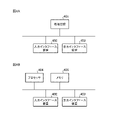
- FIG. 1 is a diagram showing a configuration example of a control device 1 according to Embodiment 1.
- Control device 1 is mounted on vehicle 100 .
- the control device 1 is connected to the camera 2 , the radar 3 and the control determination section 15 .
- the control determination unit 15 is connected with the actuator 16 .
- Camera 2 , radar 3 , control determination unit 15 , and actuator 16 are mounted on vehicle 100 .
- the control determination unit 15 is provided outside the control device 1 in FIG. 1
- the control determination unit 15 may be provided in the control device 1 .
- the control determination unit 15 is mounted on the vehicle 100 and performs an operation control of the vehicle 100.
- An automatic operation control device (not shown) ).
- the camera 2 images the surroundings of the vehicle 100.
- the camera 2 outputs an image of the surroundings of the vehicle 100 (hereinafter referred to as “captured image”) to the control device 1 .
- the radar 3 detects targets such as other vehicles existing around the vehicle 100 . It is assumed that the imaging range of the camera 2 and the target detection range of the radar 3 overlap.
- the radar 3 outputs information indicating the distance to the detected target (hereinafter referred to as “distance information”) to the control device 1 .
- the distance information includes information regarding the distance between vehicle 100 and the target, and the position and angle of the target viewed from vehicle 100 .
- a target is an object that can affect control of vehicle 100 .
- targets refer to pedestrians, bicycles, other traffic participants such as other vehicles, roads, road markings, road signs, signals, signboards, and the like.
- a target is determined in advance according to the control details of the vehicle 100 .
- the control device 1 acquires the captured image output from the camera 2 and the distance information output from the radar 3 as information about the situation around the vehicle 100 (hereinafter referred to as "surrounding situation information").
- the control device 1 infers the control amount of the vehicle 100 based on the acquired peripheral situation information. Specifically, the control device 1 infers the control amount of the vehicle 100 based on the captured image included in the acquired peripheral situation information.
- the control device 1 indicates how reliable the control amount of the vehicle 100 inferred based on the surrounding situation information is for controlling the control target equipment, in other words, the vehicle 100. (hereinafter referred to as "reliability").
- the control device 1 outputs the inferred control amount of the vehicle 100 and information about the reliability of the control amount to the control determination unit 15 . Details of the control determination unit 15 and the actuator 16 will be described later.
- the control device 1 includes a surrounding situation acquisition unit 11, a control amount inference unit 12, a target detection unit 13, and a reliability determination unit 14.
- the peripheral situation acquisition unit 11 includes a captured image acquisition unit 111 and a distance information acquisition unit 112 .
- the peripheral situation acquisition unit 11 acquires peripheral situation information from the camera 2 and the radar 3 . Specifically, the captured image acquisition unit 111 of the surrounding situation acquisition unit 11 acquires a captured image of the surroundings of the vehicle 100 from the camera 2 . A distance information acquisition unit 112 of the surrounding situation acquisition unit 11 acquires distance information to a target existing around the vehicle 100 from the radar 3 . The peripheral situation acquisition unit 11 outputs the acquired peripheral situation information to the control amount inference unit 12 and the target detection unit 13 . Here, it is assumed that the peripheral situation acquisition unit 11 outputs peripheral situation information to the control amount inference unit 12, but the peripheral situation acquisition unit 11 is not limited to this. The captured image acquired by is output to the control amount inference unit 12 .
- the control amount inference unit 12 infers the control amount of the vehicle 100 based on the surrounding situation information acquired by the surrounding situation acquisition unit 11, and also obtains a region of interest in the surrounding situation information ( (hereinafter referred to as "area of interest”) (hereinafter referred to as "area of interest information"). More specifically, the control amount inference unit 12 infers the control amount of the vehicle 100 based on the captured image included in the surrounding situation information acquired by the surrounding situation acquisition unit 11, and when inferring the control amount, To obtain region-of-interest information about a region of interest in a captured image.
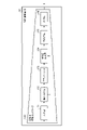
- FIG. 2 is a diagram for explaining in detail the configuration of the controlled variable inference section 12 in the control device 1 according to the first embodiment.
- the controlled variable inference unit 12 holds a controlled variable inference network 120 .
- the control amount inference network 120 is configured by a neural network that receives the captured image included in the surrounding situation information output from the surrounding situation acquisition unit 11 and outputs the control amount of the vehicle 100 . That is, the control amount inference network 120 is a machine learning model that receives a captured image and outputs the control amount of the vehicle 100 .
- the control amount inference network 120 has an input layer 121 , a convolution layer 122 , an attention layer 123 , a feature amount generation layer 124 , a fully connected layer 125 and an output layer 126 .
- the control amount inference network 120 receives a captured image in an input layer 121 and performs convolution processing on the captured image in a convolution layer 122 .
- the attention layer 123 has region-of-interest information representing the region of interest in the input captured image, and the control amount inference network 120 uses the parameters of the attention layer 123 and the convolution results of the convolution layer 122 to determine the The latent features generated by the quantity generation layer 124 are extracted.
- the control amount inference network 120 infers the control amount of the vehicle 100 with respect to the latent feature amount generated in the feature amount generation layer 124 in the fully connected layer 125 . Then, the control amount inference network 120 outputs the inferred control amount of the vehicle 100 in the output layer 126 .
- the control amount inference network 120 is trained in advance so as to output the control amount of the vehicle 100 as appropriate as possible, and in the process of learning, the attention layer 123 is also trained so as to correctly focus on meaningful areas. . That is, when the control amount of the vehicle 100 output by the control amount inference network 120 is an appropriate control amount, it can be said that the region of interest focused on by the attention layer 123 is a useful area for extracting an appropriate control amount. . Conversely, if the control amount of the vehicle 100 output by the control amount inference network 120 is not an appropriate control amount, the region of interest focused on by the attention layer 123 is not a useful area for extracting an appropriate control amount. It can be said.
- the attention layer 123 does not have the attention area information representing the attention area useful for extracting the appropriate control amount of the vehicle 100.
- the control variable inference network 120 cannot output an appropriate control variable for the vehicle 100 .
- the control amount inference unit 12 uses the control amount inference network 120 as described above to estimate the vehicle 100 based on the captured image around the vehicle 100 acquired by the surrounding situation acquisition unit 11, more specifically, the captured image acquisition unit 111. While inferring the control amount, it acquires from the control amount inference network 120 the attention area information regarding the attention area in the captured image when inferring the control amount, in other words, the attention area information that the attention layer 123 has.
- the control amount inference unit 12 outputs information about the inferred control amount of the vehicle 100 to the control determination unit 15 . In addition, the control amount inference unit 12 outputs the acquired region-of-interest information to the reliability determination unit 14 .
- the target detection unit 13 acquires the surrounding situation information acquired by the surrounding situation acquisition unit 11, in other words, the captured image acquired by the captured image acquisition unit 111 from the camera 2 and the distance acquired by the distance information acquisition unit 112 from the radar 3. Based on the information, the positions of targets existing around the vehicle 100 are detected. In Embodiment 1, the target detection unit 13 detects the position of the target as the position of the target in the captured image included in the surrounding situation information. In Embodiment 1, the position of the target in the captured image is represented by pixels on the captured image. The target detection unit 13 regards the range in which the target appears in the captured image as the position of the target, and detects pixels included in the range as information indicating the position of the target.
- the target detection unit 13 may use distance information, for example, to identify the range in which the target appears in the captured image.
- the distance information includes information regarding the position and angle of the target detected by the radar 3 as viewed from the vehicle 100 and the distance between the vehicle 100 and the target. Also, the installation position and angle of view of the camera 2 mounted on the vehicle 100 are known in advance. Therefore, based on the distance information and the captured image, the target detection unit 13 can specify in which range the target indicated by the distance information appears in the captured image.
- the target detection unit 13 may detect a target in the captured image using a known image recognition processing technique for the captured image. In this case, the target detection unit 13 does not require distance information. Therefore, the peripheral situation acquisition unit 11 does not necessarily include the distance information acquisition unit 112 .
- the target detected by the target detection unit 13 may be the entire target or a part of the target.
- the target detection unit 13 may detect the entire other vehicle as the target, or may detect only the tail lamps of the other vehicle as the target.
- the position of the target is represented by pixels included in the range in which the entire other vehicle is reflected in the captured image.
- the target detection unit 13 detects only the tail lamps of other vehicles as targets the position of the target is represented by pixels included in the range where the tail lamps are reflected in the captured image.
- the target detection unit 13 outputs information about the position of the detected target (hereinafter referred to as "target position information") to the reliability determination unit 14.
- target position information is information indicating the pixels in the range in which the target appears in the captured image.
- the reliability determining unit 14 determines the control amount of the vehicle 100 inferred by the control amount inferring unit 12 based on the region-of-interest information output from the control amount inferring unit 12 and the target position information output from the target detection unit 13. determine the reliability of Specifically, the reliability determination unit 14 compares the region of interest and the target position based on the target position information output from the target detection unit 13, and calculates the degree of matching between the region of interest and the target position. Then, the reliability of the control amount of the vehicle 100 inferred by the control amount inferring unit 12 is determined according to the calculated matching degree.
- the control amount of the vehicle 100 when the automatic driving control device or the like automatically drives the vehicle 100 should be the control amount estimated by focusing on the target, not on objects other than the target.
- the control amount of the vehicle 100 output by the control amount inference network 120 is an appropriate control amount
- the region of interest focused on by the attention layer 123 is a useful area for extracting an appropriate control amount. You can say that. Therefore, in the control device 1, the reliability determination unit 14 determines whether or not the region of interest matches the target position. The reliability of the control amount of the vehicle 100 that is output from the control amount inference network 120 is determined depending on whether or not attention is paid.
- the reliability determination unit 14 determines high reliability when the degree of matching is high, and determines low reliability when the degree of matching is low. For example, the reliability determination unit 14 calculates the degree of matching between the region of interest and the target position based on the degree of overlap between the region of interest and the target position. Further, for example, the reliability determination unit 14 determines whether or not the degree of matching between the region of interest and the target position is included in both the region of interest and the target region in units of pixels of the captured image. may be calculated based on Further, for example, the reliability determination unit 14 receives the region of interest information and the target position information, and obtains the degree of matching using a neural network that outputs the degree of matching between the region of interest and the target position. good too. It is assumed that the neural network in this case is constructed in advance.
- the reliability determined by the reliability determining unit 14 may be represented by discrete values such as “high” or “low”, or may be represented by continuously changing numerical values. To give a specific example, for example, the reliability determination unit 14 determines that the reliability is "high” when the calculated matching degree is equal to or greater than a preset threshold value (hereinafter referred to as "matching degree determination threshold value"). do. On the other hand, if the calculated degree of matching is less than the threshold value for determining the degree of matching, the reliability determination unit 14 sets the reliability to “low”. Further, for example, the reliability determination unit 14 may classify the calculated matching degrees and determine the reliability based on the classified classifications.
- a preset threshold value hereinafter referred to as "matching degree determination threshold value”
- the reliability determination unit 14 determines that the reliability is 0.2 when the degree of coincidence is 0 to 20, If the degree of matching is 21 to 40, the reliability is "0.4", if the degree of matching is 41 to 60, the reliability is "0.6”, and if the degree of matching is 61 to 80, the reliability is "0.8". , the degree of coincidence is 81 to 100, the degree of reliability may be determined as "1".
- the reliability determination unit 14 outputs the determined reliability to the control determination unit 15 .
- the control determination unit 15 determines whether or not to adopt the control amount of the vehicle 100 inferred by the control amount inference unit 12 as the control amount of the vehicle 100 based on the reliability output from the reliability determination unit 14 . .
- the control determination unit 15 compares the reliability output from the reliability determination unit 14 with a preset threshold value (hereinafter referred to as "reliability determination threshold value") to determine the control amount inference unit 12. It is determined whether or not to adopt the inferred control amount of the vehicle 100 . For example, when the reliability determined by the reliability determination unit 14 exceeds the reliability determination threshold, the control determination unit 15 determines to adopt the control amount of the vehicle 100 inferred by the control amount inference unit 12 . On the other hand, when the reliability determined by the reliability determination unit 14 is equal to or less than the reliability determination threshold, the control determination unit 15 determines not to adopt the control amount of the vehicle 100 inferred by the control amount inference unit 12 .
- control determination unit 15 determines to adopt the control amount of the vehicle 100 inferred by the control amount inference unit 12 as the control amount of the vehicle 100
- the control determination unit 15 obtains information about the control amount of the vehicle 100 inferred by the control amount inference unit 12. , to the actuator 16 .
- the control determination unit 15 determines not to adopt the control amount of the vehicle 100 inferred by the control amount inference unit 12 as the control amount of the vehicle 100
- the control determination unit 15 switches the vehicle 100 from automatic operation to manual operation, for example.
- the actuator 16 controls the vehicle 100 based on the information regarding the amount of control of the vehicle 100 output from the control determination unit 15 . Specifically, the actuator 16 performs steering wheel control, throttle control, and brake control based on the information regarding the control amount of the vehicle 100 output from the control determination unit 15 .
- the control determination unit 15 compares the reliability output from the reliability determination unit 14 with the threshold for reliability determination, and controls the control amount inference unit 12 for the vehicle 100 via the actuator 16 . , or whether to switch the vehicle 100 to manual operation without performing control based on the control amount, but this is just an example. It is possible to appropriately set what kind of determination or control the control determination unit 15 performs based on the reliability output from the reliability determination unit 14 .
- the control determination unit 15 can also adjust the control amount of the vehicle 100 to be output to the actuator 16 based on the reliability output from the reliability determination unit 14 .
- the control determination unit 15 determines the control amount of the vehicle 100 inferred by the control amount inference unit 12 and the control amount inference other than the control amount inference unit 12 based on the reliability output from the reliability determination unit 14. It is also possible to calculate a control amount (hereinafter referred to as "mixed control amount”) mixed with the control amount in the means, and output the mixed control amount to the actuator 16 .
- the control device 1 includes control amount inference means separate from the control amount inference section 12 as means for inferring the control amount of the vehicle 100 .
- the control amount inference means other than the control amount inference section 12 can be an appropriate means, for example, an in-vehicle device different from the control device 1 . Further, for example, manual operation may be used as a control amount inference means other than the control amount inference section 12 .
- the control determination unit 15 calculates the mixed control amount based on the reliability output from the reliability determination unit 14, for example, using a weighted average method. A method for calculating the mixture control amount by the control determination unit 15 will be described with a specific example. In the following explanation of the specific example, the control amount inference means other than the control amount inference section 12 is referred to as "alternative control".
- ⁇ Specific example 2> For example, it is assumed that "accelerator: 60%, brake: 0%, steering: 0°” is obtained as the control amount of the vehicle 100 inferred by the control amount inference unit 12, as in ⁇ Specific example 1>. Also, in the alternative control, it is assumed that "accelerator: 70%, brake: 0%, steering: 20°” is obtained as the control amount of the vehicle 100 as in ⁇ Specific Example 1>. However, it is assumed that the reliability output from the reliability determination unit 14 is "0.1". In this case, the control determination unit 15 calculates the mixed control amount “accelerator: 69%, brake: 0%, steering: 18°” as the control amount of the vehicle 100 .
- the formulas used to calculate the accelerator mixture control amount, the brake mixture control amount, and the steering mixture control amount are respectively the accelerator mixture control amount, the brake mixture control amount, and the , is the same as the calculation formula used to calculate the steering mixture control amount, so redundant description will be omitted.
- the control determination unit 15 outputs to the actuator 16 the mixed control amount “accelerator: 69%, brake: 0%, steering: 18°”.
- control decision The unit 15 calculates a control amount close to the control amount of the vehicle 100 inferred by the control amount inferring unit 12 as the mixed control amount, and outputs the calculated control amount to the actuator 16 .
- the control determination unit 15 calculates a control amount close to the control amount by the alternative control as the mixed control amount, and outputs the calculated control amount to the actuator 16 . In this manner, the control determining unit 15 adjusts how much of the control amount of the vehicle 100 inferred by the control amount inferring unit 12 is actually adopted according to the reliability output from the reliability determining unit 14. be able to.
- the control determination unit 15 compares the reliability output from the reliability determination unit 14 with the threshold for reliability determination, and controls the vehicle 100 via the actuator 16. 12 determines whether to perform control based on the inferred control amount of the vehicle 100, even if the control amount of the vehicle 100 is highly reliable to some extent, the control amount of the vehicle 100 does not depend on the reliability. is less than the threshold for reliability determination, it will not be adopted.
- a controlled variable with a relatively high degree of reliability is based on a target to some extent, and may be an appropriate controlled variable.
- the control determination unit 15 determines the control amount of the vehicle 100 inferred by the control amount inference unit 12 as An amount corresponding to the reliability can be employed as the control amount of the vehicle 100 to be output to the actuator 16 .
- the control determination unit 15 determines a method of determining the control amount of the vehicle 100 to be output to the actuator 16 using the reliability determination threshold, and determines the mixed control amount as the control amount of the vehicle 100 to be output to the actuator 16. It may be combined with the method of For example, when the reliability determined by the reliability determination unit 14 exceeds the reliability determination threshold, the control determination unit 15 performs control to output the control amount of the vehicle 100 inferred by the control amount inference unit 12 to the actuator 16. If it is determined to be adopted as a control amount, and the reliability determined by the reliability determination unit 14 does not exceed the threshold for reliability determination, the mixed control amount is calculated, and the calculated mixed control amount is output to the actuator 16. You may make it decide to employ
- FIG. 3 is a flow chart for explaining the operation of the control device 1 according to the first embodiment. Note that the operation of the control device 1 shown in FIG. 3 is the operation of the control device 1 when the control determination unit 15 is provided. The control device 1 repeatedly performs the operation shown in the flowchart of FIG. 3, for example, while the vehicle 100 is automatically driving.
- the peripheral situation acquisition unit 11 acquires peripheral situation information from the camera 2 and the radar 3 (step ST1). Specifically, the captured image acquisition unit 111 of the surrounding situation acquisition unit 11 acquires a captured image of the surroundings of the vehicle 100 from the camera 2 . A distance information acquisition unit 112 of the surrounding situation acquisition unit 11 acquires distance information to an object existing around the vehicle 100 from the radar 3 . The peripheral situation acquisition unit 11 outputs the acquired peripheral situation information to the control amount inference unit 12 and the target detection unit 13 .
- the control amount inference unit 12 infers the control amount of the vehicle 100 based on the surrounding situation information acquired by the surrounding situation acquisition unit 11 in step ST1, and also obtains the focus of the surrounding situation information used when inferring the control amount. Focused area information about the area is acquired (step ST2). More specifically, the control amount inference unit 12 infers the control amount of the vehicle 100 based on the captured image included in the surrounding situation information acquired by the surrounding situation acquisition unit 11, and when inferring the control amount, To obtain region-of-interest information about a region of interest in a captured image. The control amount inference unit 12 outputs information about the inferred control amount of the vehicle 100 to the control determination unit 15 . In addition, the control amount inference unit 12 outputs the acquired region-of-interest information to the reliability determination unit 14 .
- the target detection unit 13 acquires the surrounding situation information acquired by the surrounding situation acquisition unit 11 in step ST1, in other words, the captured image acquired by the captured image acquisition unit 111 from the camera 2 and the distance information acquisition unit 112 from the radar 3 The position of the target is detected based on the distance information acquired from (step ST3).
- the target detection unit 13 outputs target position information regarding the position of the detected target to the reliability determination unit 14 .
- the reliability determination unit 14 determines the control amount inference unit 12 based on the region-of-interest information output from the control amount inference unit 12 in step ST2 and the target position information output from the target detection unit 13 in step ST3. determines the reliability of the control amount of the vehicle 100 inferred by (step ST4). The reliability determination unit 14 outputs the determined reliability to the control determination unit 15 .
- the control determination unit 15 determines the control amount of the vehicle 100 inferred by the control amount inference unit 12 in step ST2 as the control amount of the vehicle 100. It is determined whether or not to adopt it as a quantity (step ST5).
- the control determination unit 15 uses information about the control amount of the vehicle 100 inferred by the control amount inference unit 12 as Output to actuator 16 .
- the actuator 16 controls the vehicle 100 based on the information regarding the control amount of the vehicle 100 output from the control determination unit 15 .
- the control determination unit 15 determines not to adopt the control amount of the vehicle 100 inferred by the control amount inference unit 12 as the control amount of the vehicle 100, the control determination unit 15 switches the vehicle 100 from automatic operation to manual operation, for example.
- control device 1 executes steps ST2 and ST3 in that order, but this order is not essential.
- the control device 1 may execute step ST3 and step ST2 in order, or may execute the operation of step ST2 and the operation of step ST3 in parallel.
- a machine learning model composed of a neural network in machine learning is generally difficult to guarantee appropriate output for all possible inputs. This is because it is difficult to completely cover every situation as learning data. In other words, the machine learning model cannot guarantee an output for an unknown state that was not subject to learning when performing machine learning.
- control amount inference network 120 learns appropriate control amount outputs for vehicle 100 with respect to various inputs, that is, captured images in the first embodiment, and appropriate control amount outputs.
- the attention layer 123 also learns to focus on the area. Therefore, when learning for certain learning data is completed and the control amount inference network 120 can output an appropriate control amount for the vehicle 100, the attention layer 123 also focuses on an appropriate area in the control amount inference network 120. It can be considered that learning is done in the same way. Conversely, if an appropriate region cannot be focused on for a certain input, the control amount output by the control amount inference network 120 for that input may not be appropriate.
- vehicle 100 If vehicle 100 is controlled using an inappropriate control amount, vehicle 100 may behave inappropriately, causing a traffic accident, vehicle failure, or the like. Therefore, when the control amount output by the control amount inference network 120 is not appropriate, the control device 1 must avoid using the control amount to control the vehicle 100 .
- the control device 1 determines whether the control amount inference network 120 focuses on a target when inferring the control amount of the vehicle 100. determines the reliability of the control amount of the vehicle 100 output from . At that time, when it is determined that the control amount inference network 120 cannot focus on the target when inferring the control amount of the vehicle 100, the control device 1 reduces the reliability so as to lower the reliability. judge. Then, the control device 1 outputs the determined reliability to the control determination unit 15 together with the control amount of the vehicle 100 inferred using the control amount inference network 120 .
- control device 1 inputs the imaged image to the control amount inference network 120 and based on the region of interest information acquired when inferring the control amount of the vehicle 100 and the target position information based on the imaged image. Therefore, it is possible to determine whether or not the control amount inferred as the control amount for controlling the controlled device is reliable.
- the control device 1 outputs the inferred control amount and the determined reliability of the control amount, so that the control determination unit 15 can, for example, determine the control amount with low reliability, in other words, the learning of the control amount inference network 120.
- Control variables inferred for inputs that may be imperfect can be prevented from being used to control the vehicle 100 . That is, the control device 1 can output a more appropriate control amount for the vehicle 100 than when outputting the control amount without determining the reliability.
- the control amount inference unit 12 infers the control amount of the vehicle 100 based on the captured image included in the surrounding situation information, and when inferring the control amount, Focused area information related to the focused area in the captured image has been acquired. Also, the target detection unit 13 detects the position of the target as the position of the target in the captured image included in the surrounding situation information. Not limited to this, the control amount inference unit 12 infers the control amount of the vehicle 100 based on information (hereinafter referred to as "point cloud data") indicating the distance and angle to targets existing around the vehicle 100. At the same time, region-of-interest information related to the region of interest in the point cloud data may be obtained when inferring the control amount.
- point cloud data information indicating the distance and angle to targets existing around the vehicle 100.
- the target detection unit 13 detects the position of the target as a position in real space based on the point cloud data.
- the control device 1 is connected to LiDAR (not shown) instead of the camera 2 and radar 3 .
- the LiDAR is mounted on the vehicle 100 .
- the LiDAR outputs the point cloud data to the control device 1 .
- the peripheral situation acquisition unit 11 of the control device 1 acquires the point cloud data output from the LiDAR as peripheral situation information.
- the peripheral situation acquisition unit 11 can be configured without the captured image acquisition unit 111 and the distance information acquisition unit 112 .
- the surrounding situation information includes point cloud data indicating the distances and angles between the vehicle 100 and targets existing around the vehicle 100, and the control amount inference unit 12 uses the point cloud data Based on, the control amount of the vehicle 100 is inferred, and the attention area information regarding the attention area in the point cloud data used when inferring the control amount is acquired. It is possible to determine whether or not the control amount inferred as the control amount for performing the control of is reliable.
- FIG. 4A and 4B are diagrams showing an example of the hardware configuration of the control device 1 according to Embodiment 1.
- FIG. An example of the hardware configuration of the control device 1 will be described assuming that the control device 1 includes the control determination unit 15 .
- the processing circuit 401 implements the functions of the surrounding situation acquisition unit 11 , the control amount inference unit 12 , the target detection unit 13 , the reliability determination unit 14 , and the control determination unit 15 . That is, the control device 1 includes a processing circuit 401 for inferring a controlled variable for controlling the vehicle 100 and determining the reliability of the inferred controlled variable.
- the processing circuitry 401 may be dedicated hardware, as shown in FIG. 4A, or a processor 404 executing a program stored in memory, as shown in FIG. 4B.
- the processing circuit 401 may be, for example, a single circuit, a composite circuit, a programmed processor, a parallel programmed processor, an ASIC (Application Specific Integrated Circuit), or an FPGA (Field-Programmable). Gate Array), or a combination thereof.
- the functions of the surrounding situation acquisition unit 11, the control amount inference unit 12, the target detection unit 13, the reliability determination unit 14, and the control determination unit 15 are software, firmware, or It is realized by a combination of software and firmware.
- Software or firmware is written as a program and stored in memory 405 .
- the processor 404 reads out and executes the programs stored in the memory 405 to obtain the peripheral situation acquisition unit 11, the control amount inference unit 12, the target detection unit 13, the reliability determination unit 14, and the control determination unit. Performs 15 functions. That is, the control device 1 includes a memory 405 for storing a program that, when executed by the processor 404, results in the execution of steps ST1 to ST5 of FIG. 3 described above.
- the program stored in the memory 405 determines the procedure or method of processing of the surrounding situation acquisition unit 11, the control amount inference unit 12, the target detection unit 13, the reliability determination unit 14, and the control determination unit 15. It can also be said that it is something that is executed by a computer.
- the memory 405 is a non-volatile or volatile memory such as RAM, ROM (Read Only Memory), flash memory, EPROM (Erasable Programmable Read Only Memory), EEPROM (Electrically Erasable Programmable Read-Only Memory).
- RAM random access memory
- ROM Read Only Memory
- flash memory a non-volatile or volatile memory
- EPROM Erasable Programmable Read Only Memory
- EEPROM Electrical Erasable Programmable Read-Only Memory
- a semiconductor memory, a magnetic disk, a flexible disk, an optical disk, a compact disk, a mini disk, a DVD (Digital Versatile Disc), or the like is applicable.
- the peripheral situation acquisition unit 11 is realized by a processing circuit 401 as dedicated hardware, and includes a control amount inference unit 12, a target detection unit 13, a reliability determination unit 14, and a control determination unit 15. can be implemented by the processor 404 reading and executing a program stored in the memory 405 .
- the control device 1 also includes an input interface device 402 and an output interface device 403 that perform wired or wireless communication with devices such as the camera 2, the radar 3, the actuator 16, or LiDAR.
- the control device 1 is an in-vehicle device mounted on the vehicle 100, and the surrounding situation acquisition unit 11, the control amount inference unit 12, the target detection unit 13, and the reliability determination unit 14 are , was provided in the control device 1 .
- the control determination unit 15 was also provided in the vehicle 100 .
- some of the surrounding situation acquisition unit 11, the control amount inference unit 12, the target detection unit 13, the reliability determination unit 14, and the control determination unit 15 are provided in the in-vehicle device of the vehicle 100.
- Others may be provided in a server connected to the in-vehicle device via a network, and the in-vehicle device and the server may constitute a control system.
- the device to be controlled is assumed to be the vehicle 100 capable of automatically driving, but this is only an example.
- the control device 1 can control various devices. Specifically, the control device 1 can set, for example, an industrial robot, an automatic guided vehicle, or an aircraft as a device to be controlled.
- the control device 1 includes the peripheral situation acquisition unit 11 that acquires the peripheral situation information related to the peripheral situation of the device to be controlled, and the peripheral situation information acquired by the peripheral situation acquisition unit 11.
- the control amount inference unit 12 for inferring the control amount of the control target device based on and acquiring the attention area information related to the attention area in the surrounding situation information used when inferring the control amount, and the surrounding situation acquisition unit 11
- the target detection unit 13 detects the position of the target existing in the vicinity of the device to be controlled, the region of interest information acquired by the control amount inference unit 12, and the target detection unit 13 detects
- a reliability determination unit 14 is provided for determining the reliability of the control amount inferred by the control amount inference unit 12 based on the target position information about the position of the target obtained. Therefore, the control device 1 can determine whether or not the control amount inferred as the control amount for controlling the device to be controlled is reliable. Then, the control device 1 can output a more appropriate control amount for the vehicle 100 than when
- Embodiment 2 the control device does not consider the control details of the control target device when inferring the control amount of the control target device and acquiring the region-of-interest information.
- Embodiment 2 describes an embodiment in which a control device infers a control amount of a controlled device and acquires region-of-interest information in consideration of the control details of the controlled device.
- the equipment to be controlled is a vehicle that can operate automatically.
- a control device performs automatic operation control in a vehicle capable of automatic operation.
- FIG. 5 is a diagram showing a configuration example of the control device 1a according to the second embodiment.
- the control device 1a is mounted on the vehicle 100a.
- the vehicle 100a is equipped with the scenario instruction device 4, and the control device 1a is connected to the scenario instruction device 4.
- the scenario instruction device 4 is, for example, a touch panel display.
- the scenario instruction device 4 receives a control scenario for automatic driving control of the vehicle 100a, and outputs information on the received control scenario (hereinafter referred to as "control scenario information") to the control device 1a.
- control scenario information information on the received control scenario
- the control scenario indicates the control content of the control target device. More specifically, a control scenario indicates an action to be implemented for a device to be controlled.
- the control scenario indicates an operation to be realized with respect to vehicle 100a.
- the control scenario is, for example, "following the preceding vehicle", “turning right at an intersection", or “stopping on the shoulder”.
- an occupant of the vehicle 100a operates the scenario instruction device 4 by touching it, inputs a control scenario from the scenario instruction device 4, and designates the control scenario.
- the scenario instruction device 4 accepts a control scenario input by the crew. Then, the scenario instruction device 4 outputs the control scenario information to the control device 1a.
- the control scenario information includes information that can identify the designated control scenario.
- control device 1a differs from the control device 1 according to the first embodiment in that a scenario acquisition unit 17 is provided. Further, the control device 1a differs from the control device 1 according to the first embodiment in the detailed configuration of the control amount inference section 12a. Further, the control device 1a differs from the control device 1 according to the first embodiment in the specific operation of the target detection unit 13a. Further, the control device 1a differs from the control device 1 according to the first embodiment in that it includes a target object database 18 of interest. Note that although the target object database 18 of FIG. 5 is provided in the control device 1a, this is merely an example. The target target database 18 may be provided outside the control device 1a at a location that can be referred to by the control device 1a.
- the scenario acquisition unit 17 acquires control scenario information output from the scenario instruction device 4 .
- the scenario acquisition unit 17 outputs the acquired control scenario information to the control amount inference unit 12a and target detection unit 13a.
- FIG. 6 is a diagram for explaining in detail the configuration of the controlled variable inference section 12a in the control device 1a according to the second embodiment.
- Control amount inference section 12 a differs from control amount inference section 12 of the first embodiment in that it includes model selection section 127 and parameter database 128 .
- the model selection unit 127 Based on the control scenario information acquired by the scenario acquisition unit 17 , the model selection unit 127 sets parameters such as layer weights of the neural network, in other words, the control amount inference network 120 .
- the parameter database 128 stores information in which control scenarios and parameters corresponding to the control scenarios are associated (hereinafter referred to as "parameter information").
- the model selection unit 127 matches the control scenario specified from the control scenario information with the control scenario of the parameter information to determine parameters corresponding to the control scenario.
- control amount inference unit 12a is provided with the parameter database 128 here, this is merely an example.
- the parameter database 128 may be provided at a location that can be referred to by the control amount inference section 12a.
- the control amount inference unit 12a uses the control amount inference network 120 in which the parameters are set based on the control scenario information acquired by the scenario acquisition unit 17 based on the surrounding situation information acquired by the surrounding situation acquisition unit 11, and the vehicle 100a. is inferred, and information on the region of interest is obtained.
- the control amount inference unit 12a uses the control amount inference network 120 in which the model selection unit 127 sets parameters based on the control scenario, and uses the peripheral situation information acquired by the peripheral situation acquisition unit 11, more specifically, the captured image Inference of the control amount of the vehicle 100a based on the captured image of the surroundings of the vehicle 100a acquired by the acquisition unit 111, and attention area information related to the attention area in the captured image when inferring the control amount, in other words, an attention layer 123 is acquired from the control amount inference network 120 .
- the control amount inference unit 12a can infer the control amount of the vehicle 100a according to the control scenario, and acquire the target area information according to the control scenario.
- the control amount inference unit 12a can infer the control amount of the vehicle 100a specialized for a given control scenario, and acquire the region of interest information.
- the control amount inferring unit 12a outputs information about the inferred control amount of the vehicle 100a according to the control scenario to the control determining unit 15. In addition, the control amount inference unit 12 a outputs the acquired target region information corresponding to the control scenario to the reliability determination unit 14 .
- the target detection unit 13 a detects the positions of targets existing around the vehicle 100 a based on the surrounding situation information acquired by the surrounding situation acquisition unit 11 and the control scenario information acquired by the scenario acquisition unit 17 .
- the target detection unit 13a detects the position of the target as the position of the target in the captured image included in the surrounding situation information.
- the position of the target in the captured image is represented by pixels on the captured image.
- the target detection unit 13a regards the range in which the target appears in the captured image as the position of the target, and detects pixels included in the range as information indicating the position of the target.
- the method for detecting the position of the target in the captured image by the target detection unit 13a is the same as the method for detecting the position of the target in the captured image by the target detection unit 13 described in the first embodiment. Therefore, redundant description is omitted.
- the target detection unit 13 detects the positions of all the targets preset by the target detection unit 13. Targets to be detected are narrowed down based on the control scenario information acquired by the unit 17 .
- the target detection unit 13a refers to the target target database 18, and selects a target whose position is to be detected (hereinafter referred to as a "detection target target") among preset targets. ) are narrowed down.
- the target detection unit 13a detects the position of the target to be detected.
- the target target database 18 holds information in which a target to be focused and an area to be focused are associated with each other (hereinafter referred to as "target information by scenario").
- FIG. 7 is a diagram showing an image of an example of the content of target object information by scenario held by the target object database 18 of interest in the second embodiment.
- vehicles, lanes, signs, and signals are set in advance as targets.
- scenario-by-scenario target information shown in FIG. 7 for example, when the control scenario is "following the preceding vehicle", all targets (vehicles, lanes, signs, and signals) are targets to be detected. , all targets should be focused on in the entire area.
- the control scenario when the control scenario is "turn right at an intersection", all targets are detection target targets. should focus on the vehicle traveling on the right side of the vehicle 100a and oncoming vehicles, and should focus on the lane on the right side of the vehicle 100a. Further, according to the scenario-specific target object information shown in FIG. 7, for example, when the control scenario is "stop", a car and a traffic light are not detected target objects.
- the target detection unit 13a refers to the target target database 18 to narrow down the detection target, and then detects the position of the narrowed down detection target.
- the target detection unit 13a outputs target position information regarding the position of the detected target, more specifically target position information regarding the position of the detected target to be detected, to the reliability determination unit 14.
- FIG. 8 is a flow chart for explaining the operation of the control device 1a according to the second embodiment.
- the operation of the control device 1a shown in FIG. 8 is the operation of the control device 1a when the control determination unit 15 is provided.
- the control device 1a repeatedly performs the operation shown in the flowchart of FIG. 8, for example, while the vehicle 100a is automatically driving.
- the specific operations of steps ST11, ST17, and ST18 are the specific operations of steps ST1, ST4, and ST5 of FIG. Since it is the same as the operation, redundant description is omitted.
- the scenario acquisition unit 17 acquires the control scenario information output from the scenario instruction device 4 (step ST12).
- the scenario acquisition unit 17 outputs the acquired control scenario information to the control amount inference unit 12a and target detection unit 13a.
- the model selection section 127 determines whether or not the control scenario is the same as the control scenario used so far (step ST13).
- step ST13 the operation of the control device 1a proceeds to step ST15.
- step ST13 When it is determined that the control scenario is different from the control scenario used so far (“NO” in step ST13), the model selection unit 127 selects the control scenario based on the control scenario information acquired by the scenario acquisition unit 17 in step ST12. , neural network, in other words, parameters such as layer weights of the control amount inference network 120 are set (step ST14). The parameters of the controlled variable inference network 120 are changed from the currently set parameters of the controlled variable inference network 120 to parameters according to the control scenario. Note that when step ST13 is executed for the first time, there is no control scenario that has been used before, so the model selection unit 127 determines that the control scenario is different from the control scenario that has been used so far. . Then, the operation of the control device 1a proceeds to step ST15.
- the control amount inference section 12a Based on the peripheral situation information acquired by the peripheral situation acquisition section 11 in step ST11, the control amount inference section 12a performs control amount inference with parameters set based on the control scenario information acquired by the scenario acquisition section 17 in step ST12. Using the network 120, the control amount of the vehicle 100a is inferred and the region of interest information is acquired (step ST15).
- the control amount inferring unit 12 a outputs information about the inferred control amount of the vehicle 100 a according to the control scenario to the control determining unit 15 .
- the control amount inference unit 12 a outputs the acquired target region information corresponding to the control scenario to the reliability determination unit 14 .
- the target detection section 13a Based on the surrounding situation information acquired by the surrounding situation acquisition section 11 in step ST11 and the control scenario information acquired by the scenario acquisition section 17 in step ST12, the target detection section 13a detects objects existing around the vehicle 100a. The position of the target is detected (step ST16). Specifically, the target detection unit 13a refers to the target target database 18, narrows down the detection target, and then detects the position of the narrowed down detection target. The target detection unit 13 a outputs target position information regarding the position of the detected target, more specifically, target position information regarding the position of the detected target to be detected, to the reliability determination unit 14 .
- control device 1a executes steps ST13 to ST16 in order, but this order is not essential.
- the control device 1a may change the order of the operations of steps ST13 to ST15 and the operation of step ST16, or may execute the operations of steps ST13 to ST15 and step ST16 in parallel.
- the control device 1a infers the control amount of the vehicle 100a using different control amount inference networks 120 according to the control scenario.
- the control device 1a can infer the control quantity of the vehicle 100a using the control quantity inference network 120 specialized for the control scenario. Since the control amount inference network 120 learns specifically for the control scenario, learning of the control amount inference network 120 becomes easy.
- each control amount inference network 120 does not need to focus on all targets under any circumstances, and may focus on targets according to the control scenario. Therefore, the control device 1a detects the position of the detection target after narrowing down the detection target according to the control scenario.
- the control device 1a compares the region of interest and the target position, and the control amount inference network 120 determines the control amount of the vehicle 100a.
- the reliability of the control amount of the vehicle 100a output from the control amount inference network 120 can be determined depending on whether the target is focused upon inference. Then, the control device 1a outputs the inferred control amount and the determined reliability of the control amount, so that the control determination unit 15 can determine, for example, the control amount with low reliability, in other words, the control amount inference network 120 It is possible to prevent the inferred control amount from being used for the control of the vehicle 100a for the input for which there is a possibility that the learning of is incomplete. That is, the control device 1a can output a more appropriate control amount for the vehicle 100a than when outputting the control amount without determining the reliability.
- the control amount inference unit 12a infers the control amount of the vehicle 100a based on the captured image included in the surrounding situation information, and when inferring the control amount, Focused area information related to the focused area in the captured image has been acquired. Also, the target detection unit 13a detects the position of the target as the position of the target in the captured image included in the surrounding situation information. Not limited to this, the control amount inference unit 12a infers the control amount of the vehicle 100a based on the point cloud data indicating the distance and angle to the target existing around the vehicle 100a, and infers the control amount. At this time, the region-of-interest information regarding the region of interest in the point cloud data may be acquired.
- the target detection unit 13a detects the position of the target as a position in real space based on the point cloud data.
- the control device 1a is connected to a LiDAR (not shown) instead of the camera 2 and radar 3.
- FIG. Note that the LiDAR is mounted on the vehicle 100a.
- the LiDAR outputs the point cloud data to the control device 1a.
- the peripheral situation acquisition unit 11 of the control device 1a acquires the point cloud data output from the LiDAR as peripheral situation information.
- the peripheral situation acquisition unit 11 can be configured without the captured image acquisition unit 111 and the distance information acquisition unit 112 .
- the surrounding situation information includes point cloud data indicating the distance and angle between the vehicle 100a and targets existing around the vehicle 100a. Based on, the control amount of the vehicle 100a is inferred, and the attention area information regarding the attention area in the point cloud data used when inferring the control amount is acquired. It is possible to determine whether or not the control amount inferred as the control amount for performing the control of is reliable.
- the hardware configuration of the control device 1a according to the second embodiment is the same as the hardware configuration of the control device 1 described with reference to FIGS. 4A and 4B in the first embodiment, so the illustration is omitted.
- An example of the hardware configuration of the control device 1a will be described assuming that the control device 1a includes the control determining unit 15.
- FIG. In the second embodiment the functions of the surrounding situation acquisition unit 11, the control amount inference unit 12a, the target detection unit 13a, the reliability determination unit 14, the control determination unit 15, and the scenario acquisition unit 17 are implemented by the processing circuit 401. That is, the control device 1a includes a processing circuit 401 for inferring a controlled variable for controlling the vehicle 100a according to a control scenario and determining the reliability of the inferred controlled variable.
- the control device 1a When the processing circuit is the processor 404, the control device 1a reads out and executes a program stored in the memory 405 to obtain the peripheral situation acquisition unit 11, the control amount inference unit 12a, the target detection unit 13a, and the reliability The functions of the degree determination unit 14, the control determination unit 15, and the scenario acquisition unit 17 are executed. That is, the control device 1a includes a memory 405 for storing a program that, when executed by the processing circuit, results in the execution of steps ST11 to ST18 of FIG. 8 described above. Further, the programs stored in the memory 405 include the peripheral situation acquisition unit 11, the control amount inference unit 12a, the target detection unit 13a, the reliability determination unit 14, the control determination unit 15, and the scenario acquisition unit 17.
- the target target database 18 is composed of, for example, a memory 405 .
- the control device 1a also includes an input interface device 402 and an output interface device 403 that perform wired or wireless communication with devices such as the camera 2, the radar 3, the scenario instruction device 4, the actuator 16, or LiDAR.
- control device 1a is an in-vehicle device mounted on the vehicle 100a, and includes the surrounding situation acquisition unit 11, the control amount inference unit 12a, the target detection unit 13a, and the reliability determination unit 14.
- scenario acquisition unit 17 is provided in the control device 1a.
- control determination unit 15 is also provided in the vehicle 100a.
- control system may be provided in the in-vehicle device 100a and in a server connected to the other in-vehicle device via a network, and the control system may be configured by the in-vehicle device and the server.
- control device 1a can also set, for example, an industrial robot, an automatic guided vehicle, or an aircraft as a device to be controlled.
- the control device 1a includes the scenario acquisition unit 17 that acquires control scenario information specifying a control scenario indicating the control content of the control target device, and the control amount inference unit 12a uses a neural network (control amount inference network 120) in which parameters are set based on the control scenario information acquired by the scenario acquisition unit 17, based on the surrounding situation information acquired by the surrounding situation acquisition unit 11, to determine the control target device
- the target detection unit 13a acquires the target area information while inferring the control amount of the target object based on the surrounding situation information acquired by the surrounding situation acquisition unit 11 and the control scenario information acquired by the scenario acquisition unit 17.
- control device 1a can determine whether or not the control amount inferred as the control amount for controlling the control target device is reliable according to the control details of the control target device. . Then, the control device 1a can output a more appropriate control amount for the vehicle 100 than when the control amount is output without determining the reliability.
- the control device can determine whether or not the control amount inferred as the control amount for controlling the device to be controlled is reliable.
- 1, 1a control device, 2 camera, 3 radar, 4 scenario instruction device 11 surrounding situation acquisition unit, 111 captured image acquisition unit, 112 distance information acquisition unit, 12, 12a control amount inference unit, 120 control amount inference network, 127 model selection unit, 128 parameter database, 13, 13a target detection unit, 14 reliability determination unit, 15 control determination unit, 16 actuator, 17 scenario acquisition unit, 18 target target database, 401 processing circuit, 402 input interface device, 403 output interface device, 404 processor, 405 memory.
Landscapes
- Engineering & Computer Science (AREA)
- Theoretical Computer Science (AREA)
- Physics & Mathematics (AREA)
- Evolutionary Computation (AREA)
- General Physics & Mathematics (AREA)
- Automation & Control Theory (AREA)
- Human Computer Interaction (AREA)
- Transportation (AREA)
- Mechanical Engineering (AREA)
- General Health & Medical Sciences (AREA)
- Multimedia (AREA)
- Health & Medical Sciences (AREA)
- Software Systems (AREA)
- Computing Systems (AREA)
- Artificial Intelligence (AREA)
- Computational Linguistics (AREA)
- Biomedical Technology (AREA)
- General Engineering & Computer Science (AREA)
- Life Sciences & Earth Sciences (AREA)
- Mathematical Physics (AREA)
- Data Mining & Analysis (AREA)
- Molecular Biology (AREA)
- Biophysics (AREA)
- Computer Vision & Pattern Recognition (AREA)
- Databases & Information Systems (AREA)
- Medical Informatics (AREA)
- Traffic Control Systems (AREA)
- Control Of Driving Devices And Active Controlling Of Vehicle (AREA)
Abstract
Description
一方、機械学習については、当該機械学習の精度が、アルゴリズムに加えて学習データの量または品質に大きく依存するため、従来、学習データに対する工夫がなされてきた。例えば、特許文献1には、多層ニューラルネットワークで作成されたモデルの作成に使用された入力項目が出力結果に与える寄与度を算出し、高寄与度の入力項目に基づいて高寄与度項目データセットを生成する技術が開示されている。
したがって、特許文献1に開示されているような技術に代表される従来技術により学習データ等を改善しても、当該学習データ等を用いて作成された機械学習モデルに基づく、実際の制御量の推論時における推論結果が、妥当である、言い換えれば、信頼するに足る推論結果である保証はないという課題があった。
実施の形態1.
実施の形態1に係る制御装置は、制御対象機器の制御を行うための制御量を推論する。
実施の形態1において、制御対象機器は、自動運転可能な車両を想定している。制御装置は、自動運転可能な車両における自動運転制御を行う。具体的には、制御装置は、車両のハンドル制御、スロットル制御、および、ブレーキ制御を行うことで、車両における自動運転制御を行うことを想定している。よって、実施の形態1において、制御装置が推論する、制御装置が車両の自動運転制御を行うための制御量は、ハンドル操舵角、スロットル開度、および、ブレーキ量を想定している。
以下の実施の形態1において、制御装置が推論するハンドル操舵角、スロットル開度、および、ブレーキ量を、まとめて「車両の制御量」ともいう。
制御装置は、推論した車両の制御量に基づいて車両のハンドル制御、スロットル制御、および、ブレーキ制御を行うことで、車両の加減速および操舵を調整する。
制御装置1は、車両100に搭載される。
制御装置1は、カメラ2、レーダ3、制御決定部15と接続される。制御決定部15は、アクチュエータ16と接続される。
カメラ2、レーダ3、制御決定部15、および、アクチュエータ16は、車両100に搭載される。
図1では、制御決定部15は、制御装置1の外部に備えられているが、制御決定部15は、制御装置1に備えられてもよい。図1に示すように、制御決定部15が制御装置1の外部に備えられる場合、例えば、制御決定部15は、車両100に搭載され、車両100の運転制御を行う自動運転制御装置(図示省略)に備えられる。
なお、カメラ2の撮像範囲と、レーダ3の物標検出範囲は重複していることを前提とする。
レーダ3は、検出した物標までの距離を示す情報(以下「距離情報」という。)を、制御装置1に出力する。距離情報には、車両100と物標との距離、および、車両100から見た物標の位置および角度に関する情報が含まれる。
実施の形態1において、物標とは、車両100の制御に影響を与え得る物体をいう。具体的には、実施の形態1において、物標とは、歩行者、自転車、または、他車両等の他の交通参加者、道路、道路標示、道路標識、信号、または、看板等をいう。物標は、車両100の制御内容に応じて予め決められている。
制御装置1は、推論した車両100の制御量、および、当該制御量の信頼度に関する情報を、制御決定部15に出力する。制御決定部15およびアクチュエータ16の詳細については、後述する。
具体的には、周辺状況取得部11の撮像画像取得部111は、カメラ2から、車両100の周辺を撮像した撮像画像を取得する。周辺状況取得部11の距離情報取得部112は、レーダ3から、車両100の周辺に存在する物標までの距離情報を取得する。
周辺状況取得部11は取得した周辺状況情報を制御量推論部12および物標検出部13に出力する。なお、ここでは、周辺状況取得部11は、制御量推論部12に対して周辺状況情報を出力するものとするが、これに限らず、周辺状況取得部11は、少なくとも、撮像画像取得部111が取得した撮像画像を、制御量推論部12に出力すればよい。
より詳細には、制御量推論部12は、周辺状況取得部11が取得した周辺状況情報に含まれる撮像画像に基づき、車両100の制御量を推論するとともに、当該制御量を推論する際の、撮像画像における着目領域に関する着目領域情報を取得する。
図2に示すように、制御量推論部12は、制御量推論ネットワーク120を保持する。
制御量推論ネットワーク120は、周辺状況取得部11から出力された周辺状況情報に含まれる撮像画像を入力とし、車両100の制御量を出力するニューラルネットワークで構成される。すなわち、制御量推論ネットワーク120は、撮像画像を入力とし、車両100の制御量を出力する機械学習モデルである。
制御量推論ネットワーク120は、入力層121で撮像画像を受け取り、畳み込み層122で当該撮像画像に対して畳み込み処理を行う。アテンション層123は、入力された撮像画像における着目領域をあらわす着目領域情報を有しており、制御量推論ネットワーク120は、当該アテンション層123のパラメータと、畳み込み層122の畳み込み結果とに基づき、特徴量生成層124で生成された潜在的な特徴量を抽出する。制御量推論ネットワーク120は、全結合層125で、特徴量生成層124で生成された潜在的な特徴量に対して車両100の制御量を推論する。そして、制御量推論ネットワーク120は、出力層126で、推論した車両100の制御量の出力を行う。
すなわち、制御量推論ネットワーク120が出力する車両100の制御量が適切な制御量である場合、アテンション層123が着目する着目領域は、適切な制御量を抽出するのに有用な領域であるといえる。なお、逆に、制御量推論ネットワーク120が出力する車両100の制御量が適切な制御量でない場合、アテンション層123が着目する着目領域は、適切な制御量を抽出するのに有用な領域ではないといえる。例えば、制御量推論ネットワーク120に未知の撮像画像が入力された場合、アテンション層123は、適切な車両100の制御量を抽出するのに有用な着目領域をあらわす着目領域情報を有しておらず、制御量推論ネットワーク120は適切な車両100の制御量を出力できない。
制御量推論部12は、推論した車両100の制御量に関する情報を制御決定部15に出力する。また、制御量推論部12は、取得した着目領域情報を、信頼度判定部14に出力する。
実施の形態1において、撮像画像における物標の位置は、撮像画像上の画素であらわされる。物標検出部13は、撮像画像において物標がうつっている範囲を物標の位置とし、当該範囲に含まれている画素を、物標の位置を示す情報として検出する。
具体的には、信頼度判定部14は、物標検出部13から出力された物標位置情報に基づき着目領域と物標位置の比較を行い、着目領域と物標位置との一致度を算出し、算出した一致度に応じて、制御量推論部12が推論した車両100の制御量の信頼度を判定する。
一方、上述のとおり、制御量推論ネットワーク120が出力する車両100の制御量が適切な制御量である場合、アテンション層123が着目する着目領域は、適切な制御量を抽出するのに有用な領域であるといえる。
そこで、制御装置1において、信頼度判定部14は、着目領域が物標位置と一致しているか否か、言い換えれば、制御量推論ネットワーク120が車両100の制御量の推論の際に物標に着目できているか否かによって、当該制御量推論ネットワーク120から出力される車両100の制御量の信頼度を判定する。
例えば、信頼度判定部14は、着目領域と物標位置との一致度を、着目領域と物標位置の重複度合いに基づいて算出する。また、例えば、信頼度判定部14は、着目領域と物標位置との一致度を、撮像画像の画素単位で、着目領域および物標領域のいずれにも含まれているか否かを判定した結果に基づいて算出してもよい。また、例えば、信頼度判定部14は、着目領域情報と物標位置情報とを入力とし、着目領域と物標位置との一致度を出力するニューラルネットワークを用いて、当該一致度を取得してもよい。なお、この場合のニューラルネットワークは、予め構築されているものとする。
具体例を挙げると、例えば、信頼度判定部14は、算出した一致度が、予め設定されている閾値(以下「一致度判定用閾値」という。)以上の場合、信頼度は「高い」とする。一方、信頼度判定部14は、算出した一致度が一致度判定用閾値未満の場合、信頼度は「低い」とする。
また、例えば、信頼度判定部14は、算出した一致度を分類分けし、分類分けされた分類によって、信頼度を判定するようにしてもよい。例えば、一致度が0~100であらわされ、信頼度は0~1の数値であらわされるとすると、信頼度判定部14は、一致度が0~20の場合は信頼度「0.2」、一致度が21~40の場合は信頼度「0.4」、一致度が41~60の場合は信頼度「0.6」、一致度が61~80の場合は信頼度「0.8」、一致度が81~100の場合は信頼度「1」というように、信頼度を判定してもよい。
例えば、制御決定部15は、信頼度判定部14から出力された信頼度と、予め設定されている閾値(以下「信頼度判定用閾値」という。)との比較によって、制御量推論部12が推論した車両100の制御量を採用するか否かを決定する。例えば、制御決定部15は、信頼度判定部14が判定した信頼度が信頼度判定用閾値を超えている場合、制御量推論部12が推論した車両100の制御量を採用すると決定する。一方、制御決定部15は、信頼度判定部14が判定した信頼度が信頼度判定用閾値以下である場合、制御量推論部12が推論した車両100の制御量を採用しないと決定する。
一方、制御決定部15は、制御量推論部12が推論した車両100の制御量を、当該車両100の制御量として採用しないと決定した場合、例えば、車両100を自動運転から手動運転に切り替える。
例えば、制御決定部15は、信頼度判定部14から出力された信頼度に基づいて、制御量推論部12が推論した車両100の制御量と、制御量推論部12とは別の制御量推論手段における制御量とを混ぜ合わせた制御量(以下「混合制御量」という。)を算出し、混合制御量をアクチュエータ16に出力することもできる。なお、この一例では、制御装置1は、車両100の制御量を推論する手段として、制御量推論部12とは別の制御量推論手段を備えていることを前提としている。制御量推論部12とは別の制御量推論手段は、適宜の手段とすることができ、例えば、制御装置1とは別の車載装置である。また、例えば、手動運転を制御量推論部12とは別の制御量推論手段としてもよい。
制御決定部15は、例えば、重み付き平均手法を用いて、信頼度判定部14から出力された信頼度に基づき、混合制御量を算出する。
制御決定部15が混合制御量を算出する方法について、具体例を挙げて説明する。なお、以下の具体例の説明では、制御量推論部12とは別の制御量推論手段を、「代替制御」という。
例えば、制御量推論部12が推論した車両100の制御量として、「アクセル:60%、ブレーキ:0%、ステアリング:0°」が得られたとする。
一方、代替制御では、車両100の制御量として、「アクセル:70%、ブレーキ:0%、ステアリング:20°」が得られたとする。
また、信頼度判定部14から出力された信頼度は、「0.9」だったとする。
この場合、制御決定部15は、アクセルの混合制御量を、以下の計算によって、「61%」と算出する。
60×0.9+70×(1-0.9)=61
また、制御決定部15は、ブレーキの混合制御量を、以下の計算式によって、「0%」と算出する。
0×0.9+0×(1-0.9)=0
また、制御決定部15は、ステアリングの混合制御量を、以下の計算式によって、「2°」と算出する。
0×0.9+20×(1-0.9)=2
そして、制御決定部15は、車両100の制御量として、混合制御量「アクセル:61%、ブレーキ:0%、ステアリング:2°」を、アクチュエータ16に出力する。
例えば、制御量推論部12が推論した車両100の制御量として、<具体例1>同様、「アクセル:60%、ブレーキ:0%、ステアリング:0°」が得られたとする。
また、代替制御でも、車両100の制御量として、<具体例1>同様、「アクセル:70%、ブレーキ:0%、ステアリング:20°」が得られたとする。
しかし、信頼度判定部14から出力された信頼度は、「0.1」だったとする。
この場合、制御決定部15は、車両100の制御量として、混合制御量「アクセル:69%、ブレーキ:0%、ステアリング:18°」を算出する。
なお、アクセルの混合制御量、ブレーキの混合制御量、および、ステアリングの混合制御量の計算に用いる計算式は、それぞれ、<具体例1>におけるアクセルの混合制御量、ブレーキの混合制御量、および、ステアリングの混合制御量の計算に用いる計算式と同様であるため重複した説明を省略する。
そして、制御決定部15は、混合制御量「アクセル:69%、ブレーキ:0%、ステアリング:18°」を、アクチュエータ16に出力する。
一方、<具体例2>のように、信頼度判定部14から出力された信頼度が低い場合、すなわち、制御量推論部12が推論した車両100の制御量の信頼度が低いといえる場合、制御決定部15は、混合制御量として、代替制御による制御量に近い制御量を算出し、アクチュエータ16に出力することになる。
このように、制御決定部15は、制御量推論部12が推論した車両100の制御量について、信頼度判定部14から出力された信頼度に応じて、実際にどれぐらい採用するかを調整することができる。
そこで、<具体例1>および<具体例2>のように、信頼度判定部14から出力された信頼度に基づいて、制御量推論部12が推論した車両100の制御量と、制御量推論部12とは別の制御量推論手段における制御量とを混ぜ合わせた混合制御量を算出可能とすることで、制御決定部15は、制御量推論部12が推論した車両100の制御量を、その信頼度に応じた分だけ、アクチュエータ16に出力する車両100の制御量として採用することができる。
図3は、実施の形態1に係る制御装置1の動作を説明するためのフローチャートである。
なお、図3に示す制御装置1の動作は、制御決定部15を備えた場合の制御装置1の動作としている。制御装置1は、図3のフローチャートに示す動作を、例えば、車両100が自動運転中、繰り返し行う。
具体的には、周辺状況取得部11の撮像画像取得部111は、カメラ2から、車両100の周辺を撮像した撮像画像を取得する。周辺状況取得部11の距離情報取得部112は、レーダ3から、車両100の周辺に存在する物体までの距離情報を取得する。
周辺状況取得部11は取得した周辺状況情報を制御量推論部12および物標検出部13に出力する。
より詳細には、制御量推論部12は、周辺状況取得部11が取得した周辺状況情報に含まれる撮像画像に基づき、車両100の制御量を推論するとともに、当該制御量を推論する際の、撮像画像における着目領域に関する着目領域情報を取得する。
制御量推論部12は、推論した車両100の制御量に関する情報を制御決定部15に出力する。また、制御量推論部12は、取得した着目領域情報を、信頼度判定部14に出力する。
物標検出部13は、検出した物標の位置に関する物標位置情報を、信頼度判定部14に出力する。
信頼度判定部14は、判定した信頼度を、制御決定部15に出力する。
制御決定部15は、制御量推論部12が推論した車両100の制御量を当該車両100の制御量として採用すると決定した場合、制御量推論部12が推論した車両100の制御量に関する情報を、アクチュエータ16に出力する。
アクチュエータ16は、制御決定部15から出力された車両100の制御量に関する情報に基づき、車両100の制御を行う。
一方、制御決定部15は、制御量推論部12が推論した車両100の制御量を、当該車両100の制御量として採用しないと決定した場合、例えば、車両100を自動運転から手動運転に切り替える。
このように、制御装置1は、制御量推論ネットワーク120に撮像画像を入力して車両100の制御量を推論する際に取得した着目領域情報と、当該撮像画像に基づく物標位置情報とに基づいて、制御対象機器の制御を行うための制御量として推論された制御量が信頼に足るものであるか否かを判定することができる。
制御装置1が、推論した制御量とともに、判定した当該制御量の信頼度を出力することで、制御決定部15は、例えば、信頼度が低い制御量、言い換えれば、制御量推論ネットワーク120の学習が不完全である可能性がある入力に対して推論された制御量が、車両100の制御に用いられないようにすることができる。
つまり、制御装置1は、信頼度を判定することなく制御量を出力する場合に比べ、より適切な車両100の制御量の出力を行うことができる。
これに限らず、制御量推論部12は、車両100の周辺に存在する物標との距離および角度を示す情報(以下「点群データ」という。)に基づき、車両100の制御量を推論するとともに、当該制御量を推論する際の、点群データにおける着目領域に関する着目領域情報を取得してもよい。この場合、物標検出部13は、物標の位置を、点群データに基づく実空間上の位置として検出する。
この場合、制御装置1は、カメラ2およびレーダ3に代えて、LiDAR(図示省略)と接続される。なお、LiDARは車両100に搭載されている。LiDARは、上記点群データを制御装置1に出力する。制御装置1の周辺状況取得部11は、LiDARから出力された点群データを、周辺状況情報として取得する。
なお、この場合、周辺状況取得部11は、撮像画像取得部111および距離情報取得部112を備えない構成とできる。
このように、制御装置1において、周辺状況情報は、車両100と当該車両100の周辺に存在する物標との距離および角度を示す点群データを含み、制御量推論部12は、点群データに基づき、車両100の制御量を推論するとともに、当該制御量を推論する際に用いた、点群データにおける着目領域に関する着目領域情報を取得するようにしても、制御装置1は、制御対象機器の制御を行うための制御量として推論された制御量が信頼に足るものであるか否かを判定することができる。
制御装置1は制御決定部15を備えているものとして、制御装置1のハードウェア構成の一例を説明する。
実施の形態1において、周辺状況取得部11と、制御量推論部12と、物標検出部13と、信頼度判定部14と、制御決定部15の機能は、処理回路401により実現される。すなわち、制御装置1は、車両100を制御するための制御量を推論し、推論した制御量の信頼度を判定する制御を行うための処理回路401を備える。
処理回路401は、図4Aに示すように専用のハードウェアであっても、図4Bに示すようにメモリに格納されるプログラムを実行するプロセッサ404であってもよい。
また、制御装置1は、カメラ2、レーダ3、アクチュエータ16、または、LiDAR等の装置と、有線通信または無線通信を行う入力インタフェース装置402および出力インタフェース装置403を備える。
これに限らず、周辺状況取得部11と、制御量推論部12と、物標検出部13と、信頼度判定部14と、制御決定部15のうち、一部が車両100の車載装置に備えられ、その他は当該車載装置とネットワークを介して接続されるサーバに備えられて、車載装置とサーバとで制御システムを構成してもよい。
制御装置1は、種々の機器の制御を行うことができる。具体的には、制御装置1は、例えば、産業用ロボット、無人搬送車、または、航空機を、制御対象機器とすることもできる。
実施の形態1では、制御装置は、制御対象機器の制御量の推論、および、着目領域情報の取得を行うにあたり、制御対象機器の制御内容を考慮していなかった。
実施の形態2では、制御装置が、制御対象機器の制御内容を考慮して、当該制御対象機器の制御量の推論および着目領域情報の取得を行う実施の形態について説明する。
制御装置1aは、車両100aに搭載される。
実施の形態2において、車両100aには、シナリオ指示装置4が搭載されており、制御装置1aはシナリオ指示装置4と接続される。
シナリオ指示装置4は、例えば、タッチパネル式のディスプレイである。シナリオ指示装置4は、車両100aの自動運転制御のための制御シナリオを受け付け、受け付けた制御シナリオに関する情報(以下「制御シナリオ情報」という。)を、制御装置1aに出力する。実施の形態2において、制御シナリオは、制御対象機器の制御内容を示す。より詳細には、制御シナリオは、制御対象機器に対して実現させようとする動作を示す。すなわち、ここでは、制御シナリオは、車両100aに対して実現させようとする動作を示す。具体例を挙げると、制御シナリオは、例えば、「先行車両への追従」、「交差点の右折」、または、「路肩への停車」である。
例えば、車両100aの乗員は、シナリオ指示装置4をタッチする等して操作し、シナリオ指示装置4から制御シナリオを入力し、当該制御シナリオを指定する。シナリオ指示装置4は、乗員によって入力された制御シナリオを受け付ける。そして、シナリオ指示装置4は、制御シナリオ情報を制御装置1aに出力する。制御シナリオ情報には、指定された制御シナリオを特定可能な情報が含まれる。
制御装置1aは、実施の形態1に係る制御装置1とは、シナリオ取得部17を備えた点が異なる。また、制御装置1aは、実施の形態1に係る制御装置1とは、制御量推論部12aの詳細な構成が異なる。また、制御装置1aは、実施の形態1に係る制御装置1とは、物標検出部13aの具体的な動作が異なる。また、制御装置1aは、実施の形態1に係る制御装置1とは、着目物標データベース18を備える点が異なる。
なお、図5では、着目物標データベース18は制御装置1aに備えられているが、これは一例に過ぎない。着目物標データベース18は、制御装置1aの外部の、制御装置1aが参照可能な場所に備えられてもよい。
シナリオ取得部17は、取得した制御シナリオ情報を、制御量推論部12aおよび物標検出部13aに出力する。
実施の形態2に係る制御量推論部12aの構成について、実施の形態1にて図2を用いて説明した制御量推論部12と同様の構成には、同じ符号を付して重複した説明を省略する。
制御量推論部12aは、実施の形態1の制御量推論部12とは、モデル選択部127およびパラメータデータベース128を備える点が異なる。
パラメータデータベース128は、制御シナリオと、当該制御シナリオに対応するパラメータとが対応付けられた情報(以下「パラメータ情報」という。)を記憶している。
モデル選択部127は、制御シナリオ情報から特定した制御シナリオと、パラメータ情報の制御シナリオとのつきあわせを行って、制御シナリオに対応するパラメータを決定する。
すなわち、制御量推論部12aは、モデル選択部127が制御シナリオに基づいてパラメータを設定した制御量推論ネットワーク120を用いて、周辺状況取得部11が取得した周辺状況情報、より詳細には撮像画像取得部111によって取得された車両100aの周辺の撮像画像に基づく車両100aの制御量を推論するとともに、当該制御量を推論する際の、撮像画像における着目領域に関する着目領域情報、言い換えれば、アテンション層123が有する着目領域情報を、制御量推論ネットワーク120から取得する。
これにより、制御量推論部12aは、制御シナリオに応じた車両100aの制御量の推論、および、制御シナリオに応じた着目領域情報の取得を行うことができる。つまり、制御量推論部12aは、与えられた制御シナリオに特化した車両100aの制御量の推論、および、着目領域情報の取得を行うことができる。
実施の形態2において、撮像画像における物標の位置は、撮像画像上の画素であらわされる。物標検出部13aは、撮像画像において物標がうつっている範囲を物標の位置とし、当該範囲に含まれている画素を、物標の位置を示す情報として検出する。
物標検出部13aが撮像画像における物標の位置を検出する方法は、実施の形態1にて説明した、物標検出部13が撮像画像における物標の位置を検出する方法と同様の方法とすればよいため、重複した説明を省略する。
ただし、実施の形態1において物標検出部13が予め設定されている全ての物標を、位置を検出する対象としていたのに対し、実施の形態2では、物標検出部13aは、シナリオ取得部17が取得した制御シナリオ情報に基づいて、検出対象とする物標の絞り込みを行う。具体的には、物標検出部13aは、着目物標データベース18を参照して、予め設定されている物標のうち、位置を検出する対象とする物標(以下「検出対象物標」という。)の絞り込みを行う。物標検出部13aは、検出対象物標の位置を検出する。
ここで、図7は、実施の形態2において、着目物標データベース18が保持するシナリオ別物標情報の内容の一例のイメージを示す図である。なお、ここでは、予め、物標として、自動車、車線、標識、および、信号が設定されているとする。
図7に示すシナリオ別物標情報によれば、例えば、制御シナリオが「先行車への追従」である場合、全ての物標(自動車、車線、標識、および、信号)が検出対象物標であり、全ての物標を、全領域で着目すべきということになる。また、図7に示すシナリオ別物標情報によれば、例えば、制御シナリオが「交差点の右折」である場合、全ての物標が検出対象物標であるが、検出対象物標のうち、自動車については車両100aの右側を走行する車両および対向車に着目し、車線については車両100aの右側の車線に注目すべきということになる。また、図7に示すシナリオ別物標情報によれば、例えば、制御シナリオが「停車」である場合、自動車および信号は検出対象物標とはしないことになる。
物標検出部13aは、着目物標データベース18を参照して、検出対象物標を絞り込んだ上で、絞り込んだ検出対象物標の位置を検出する。
図8は、実施の形態2に係る制御装置1aの動作を説明するためのフローチャートである。
なお、図8に示す制御装置1aの動作は、制御決定部15を備えた場合の制御装置1aの動作としている。制御装置1aは、図8のフローチャートに示す動作を、例えば、車両100aが自動運転中、繰り返し行う。
図8において、ステップST11、ステップST17、および、ステップST18の具体的な動作は、それぞれ、実施の形態1にて説明済みの、図3のステップST1、ステップST4、および、ステップST5の具体的な動作と同様であるため、重複した説明を省略する。
シナリオ取得部17は、取得した制御シナリオ情報を、制御量推論部12aおよび物標検出部13aに出力する。
なお、ステップST13が1回目に実行される場合は、それより前に使用していた制御シナリオがないため、モデル選択部127は、制御シナリオはこれまで使用していた制御シナリオと異なると判定する。そして、制御装置1aの動作はステップST15に進む。
制御量推論部12aは、推論した、制御シナリオに応じた車両100aの制御量に関する情報を、制御決定部15に出力する。また、制御量推論部12aは、取得した、制御シナリオに応じた着目領域情報を、信頼度判定部14に出力する。
具体的には、物標検出部13aは、着目物標データベース18を参照して、検出対象物標を絞り込んだ上で、絞り込んだ検出対象物標の位置を検出する。
物標検出部13aは、検出した物標の位置に関する物標位置情報、より詳細には、検出した検出対象物標の位置に関する物標位置情報を、信頼度判定部14に出力する。
制御量推論ネットワーク120は、制御シナリオに特化して学習するため、制御量推論ネットワーク120の学習が容易となる。
制御シナリオが設定される場合、各制御量推論ネットワーク120はいかなる状況下でも全ての物標に対して着目する必要はなく、制御シナリオに応じた物標に着目できていればよい。そこで、制御装置1aは、制御シナリオに応じて検出対象物標の絞り込みを行った上で当該検出対象物標の位置を検出する。これにより、制御装置1aは、制御シナリオごとに制御量推論ネットワーク120が構成される場合であっても、着目領域と物標位置の比較を行い、制御量推論ネットワーク120が車両100aの制御量の推論の際に物標に着目しているかによって、当該制御量推論ネットワーク120から出力される車両100aの制御量の信頼度の判定を行うことができる。
そして、制御装置1aが、推論した制御量とともに、判定した当該制御量の信頼度を出力することで、制御決定部15は、例えば、信頼度が低い制御量、言い換えれば、制御量推論ネットワーク120の学習が不完全である可能性がある入力に対して推論された制御量が、車両100aの制御に用いられないようにすることができる。
つまり、制御装置1aは、信頼度を判定することなく制御量を出力する場合に比べ、より適切な車両100aの制御量の出力を行うことができる。
これに限らず、制御量推論部12aは、車両100aの周辺に存在する物標との距離および角度を示す点群データに基づき、車両100aの制御量を推論するとともに、当該制御量を推論する際の、点群データにおける着目領域に関する着目領域情報を取得してもよい。この場合、物標検出部13aは、物標の位置を、点群データに基づく実空間上の位置として検出する。
この場合、制御装置1aは、カメラ2およびレーダ3に代えて、LiDAR(図示省略)と接続される。なお、LiDARは車両100aに搭載されている。LiDARは、上記点群データを制御装置1aに出力する。制御装置1aの周辺状況取得部11は、LiDARから出力された点群データを、周辺状況情報として取得する。
なお、この場合、周辺状況取得部11は、撮像画像取得部111および距離情報取得部112を備えない構成とできる。
このように、制御装置1aにおいて、周辺状況情報は、車両100aと当該車両100aの周辺に存在する物標との距離および角度を示す点群データを含み、制御量推論部12aは、点群データに基づき、車両100aの制御量を推論するとともに、当該制御量を推論する際に用いた、点群データにおける着目領域に関する着目領域情報を取得するようにしても、制御装置1aは、制御対象機器の制御を行うための制御量として推論された制御量が信頼に足るものであるか否かを判定することができる。
実施の形態2において、周辺状況取得部11と、制御量推論部12aと、物標検出部13aと、信頼度判定部14と、制御決定部15と、シナリオ取得部17の機能は、処理回路401により実現される。すなわち、制御装置1aは、制御シナリオに応じて、車両100aを制御するための制御量を推論し、推論した制御量の信頼度を判定する制御を行うための処理回路401を備える。
処理回路がプロセッサ404の場合、制御装置1aは、メモリ405に記憶されたプログラムを読み出して実行することにより、周辺状況取得部11と、制御量推論部12aと、物標検出部13aと、信頼度判定部14と、制御決定部15と、シナリオ取得部17の機能を実行する。すなわち、制御装置1aは、処理回路により実行されるときに、上述の図8のステップST11~ステップST18が結果的に実行されることになるプログラムを格納するためのメモリ405を備える。また、メモリ405に記憶されたプログラムは、周辺状況取得部11と、制御量推論部12aと、物標検出部13aと、信頼度判定部14と、制御決定部15と、シナリオ取得部17の手順または方法をコンピュータに実行させるものであるとも言える。
着目物標データベース18は、例えば、メモリ405で構成される。
また、制御装置1aは、カメラ2、レーダ3、シナリオ指示装置4、アクチュエータ16、または、LiDAR等の装置と、有線通信または無線通信を行う入力インタフェース装置402および出力インタフェース装置403を備える。
これに限らず、周辺状況取得部11と、制御量推論部12aと、物標検出部13aと、信頼度判定部14と、制御決定部15と、シナリオ取得部17のうち、一部が車両100aの車載装置に備えられ、その他は当該車載装置とネットワークを介して接続されるサーバに備えられて、車載装置とサーバとで制御システムを構成してもよい。
Claims (8)
- 制御対象機器の周辺の状況に関する周辺状況情報を取得する周辺状況取得部と、
前記周辺状況取得部が取得した前記周辺状況情報に基づき、前記制御対象機器の制御量を推論するとともに、前記制御量を推論する際に用いた、前記周辺状況情報における着目領域に関する着目領域情報を取得する制御量推論部と、
前記周辺状況取得部が取得した前記周辺状況情報に基づき、前記制御対象機器の周辺に存在する物標の位置を検出する物標検出部と、
前記制御量推論部が取得した前記着目領域情報と、前記物標検出部が検出した前記物標の位置に関する物標位置情報とに基づき、前記制御量推論部が推論した前記制御量の信頼度を判定する信頼度判定部
とを備えた制御装置。 - 前記制御量推論部は、学習済みのニューラルネットワークを用いて、前記制御量を推論するとともに前記着目領域情報を取得する
ことを特徴とする請求項1記載の制御装置。 - 前記信頼度判定部が判定した前記制御量の前記信頼度に基づき、前記制御量推論部が推論した前記制御量を前記制御対象機器の前記制御量として採用するか否かを決定する制御決定部を備えた
ことを特徴とする請求項1記載の制御装置。 - 前記周辺状況情報は、前記制御対象機器の周辺を撮像した撮像画像を含み、
前記制御量推論部は、前記撮像画像に基づき、前記制御対象機器の前記制御量を推論するとともに、当該制御量を推論する際に用いた、前記撮像画像における着目領域に関する着目領域情報を取得する
ことを特徴とする請求項1記載の制御装置。 - 前記周辺状況情報は、前記制御対象機器と前記制御対象機器の周辺に存在する前記物標との距離および角度を示す点群データを含み、
前記制御量推論部は、前記点群データに基づき、前記制御対象機器の前記制御量を推論するとともに、当該制御量を推論する際に用いた、前記点群データにおける着目領域に関する着目領域情報を取得する
ことを特徴とする請求項1記載の制御装置。 - 前記物標検出部は、前記物標の一部の位置を、前記物標の位置として検出する
ことを特徴とする請求項1記載の制御装置。 - 前記制御対象機器の制御内容を示す制御シナリオが指定された制御シナリオ情報を取得するシナリオ取得部を備え、
前記制御量推論部は、前記周辺状況取得部が取得した前記周辺状況情報に基づき、前記シナリオ取得部が取得した前記制御シナリオ情報に基づいてパラメータが設定された前記ニューラルネットワークを用いて、前記制御対象機器の前記制御量を推論するとともに前記着目領域情報を取得し、
前記物標検出部は、前記周辺状況取得部が取得した前記周辺状況情報と、前記シナリオ取得部が取得した前記制御シナリオ情報に基づいて、前記物標の位置を検出する
ことを特徴とする請求項2記載の制御装置。 - 周辺状況取得部が、制御対象機器の周辺の状況に関する周辺状況情報を取得するステップと、
制御量推論部が、前記周辺状況取得部が取得した前記周辺状況情報に基づき、前記制御対象機器の制御量を推論するとともに、前記制御量を推論する際に用いた、前記周辺状況情報における着目領域に関する着目領域情報を取得するステップと、
物標検出部が、前記周辺状況取得部が取得した前記周辺状況情報に基づき、前記制御対象機器の周辺に存在する物標の位置を検出するステップと、
信頼度判定部が、前記制御量推論部が取得した前記着目領域情報と、前記物標検出部が検出した前記物標の位置に関する物標位置情報とに基づき、前記制御量推論部が推論した前記制御量の信頼度を判定するステップ
とを備えた制御方法。
Priority Applications (5)
| Application Number | Priority Date | Filing Date | Title |
|---|---|---|---|
| JP2023508147A JP7370495B2 (ja) | 2021-03-22 | 2021-03-22 | 制御装置および制御方法 |
| CN202180095500.6A CN116963951A (zh) | 2021-03-22 | 2021-03-22 | 控制装置及控制方法 |
| DE112021007341.9T DE112021007341T5 (de) | 2021-03-22 | 2021-03-22 | Steuervorrichtung und Steuerverfahren |
| US18/270,549 US20240067189A1 (en) | 2021-03-22 | 2021-03-22 | Control device and control method |
| PCT/JP2021/011618 WO2022201222A1 (ja) | 2021-03-22 | 2021-03-22 | 制御装置および制御方法 |
Applications Claiming Priority (1)
| Application Number | Priority Date | Filing Date | Title |
|---|---|---|---|
| PCT/JP2021/011618 WO2022201222A1 (ja) | 2021-03-22 | 2021-03-22 | 制御装置および制御方法 |
Publications (1)
| Publication Number | Publication Date |
|---|---|
| WO2022201222A1 true WO2022201222A1 (ja) | 2022-09-29 |
Family
ID=83395366
Family Applications (1)
| Application Number | Title | Priority Date | Filing Date |
|---|---|---|---|
| PCT/JP2021/011618 Ceased WO2022201222A1 (ja) | 2021-03-22 | 2021-03-22 | 制御装置および制御方法 |
Country Status (5)
| Country | Link |
|---|---|
| US (1) | US20240067189A1 (ja) |
| JP (1) | JP7370495B2 (ja) |
| CN (1) | CN116963951A (ja) |
| DE (1) | DE112021007341T5 (ja) |
| WO (1) | WO2022201222A1 (ja) |
Citations (4)
| Publication number | Priority date | Publication date | Assignee | Title |
|---|---|---|---|---|
| JP2017105453A (ja) * | 2015-12-08 | 2017-06-15 | ローベルト ボツシユ ゲゼルシヤフト ミツト ベシユレンクテル ハフツングRobert Bosch Gmbh | 自動車の運転支援機能を検証する方法 |
| JP2017220197A (ja) * | 2016-06-12 | 2017-12-14 | バイドゥ オンライン ネットワーク テクノロジー (ベイジン) カンパニー リミテッド | 車両制御方法と装置及び判断モジュールの獲得方法と装置 |
| JP2019501435A (ja) * | 2016-08-29 | 2019-01-17 | バイドゥ・ユーエスエイ・リミテッド・ライアビリティ・カンパニーBaidu USA LLC | 自律走行車の走行を決定するための周辺環境を構築する方法及びシステム |
| WO2021044486A1 (ja) * | 2019-09-02 | 2021-03-11 | 三菱電機株式会社 | 自動運転制御装置および自動運転制御方法 |
Family Cites Families (2)
| Publication number | Priority date | Publication date | Assignee | Title |
|---|---|---|---|---|
| JP6458072B2 (ja) | 2017-03-30 | 2019-01-23 | 株式会社Jsol | 多層ニューラルネットワーク(ディープラーニング)の性能向上のための高寄与度項目の抽出システム、抽出方法及び抽出プログラム |
| WO2022201276A1 (ja) * | 2021-03-23 | 2022-09-29 | 三菱電機株式会社 | 信頼度判定装置および信頼度判定方法 |
-
2021
- 2021-03-22 CN CN202180095500.6A patent/CN116963951A/zh not_active Withdrawn
- 2021-03-22 US US18/270,549 patent/US20240067189A1/en not_active Abandoned
- 2021-03-22 WO PCT/JP2021/011618 patent/WO2022201222A1/ja not_active Ceased
- 2021-03-22 DE DE112021007341.9T patent/DE112021007341T5/de active Pending
- 2021-03-22 JP JP2023508147A patent/JP7370495B2/ja active Active
Patent Citations (4)
| Publication number | Priority date | Publication date | Assignee | Title |
|---|---|---|---|---|
| JP2017105453A (ja) * | 2015-12-08 | 2017-06-15 | ローベルト ボツシユ ゲゼルシヤフト ミツト ベシユレンクテル ハフツングRobert Bosch Gmbh | 自動車の運転支援機能を検証する方法 |
| JP2017220197A (ja) * | 2016-06-12 | 2017-12-14 | バイドゥ オンライン ネットワーク テクノロジー (ベイジン) カンパニー リミテッド | 車両制御方法と装置及び判断モジュールの獲得方法と装置 |
| JP2019501435A (ja) * | 2016-08-29 | 2019-01-17 | バイドゥ・ユーエスエイ・リミテッド・ライアビリティ・カンパニーBaidu USA LLC | 自律走行車の走行を決定するための周辺環境を構築する方法及びシステム |
| WO2021044486A1 (ja) * | 2019-09-02 | 2021-03-11 | 三菱電機株式会社 | 自動運転制御装置および自動運転制御方法 |
Also Published As
| Publication number | Publication date |
|---|---|
| CN116963951A (zh) | 2023-10-27 |
| DE112021007341T5 (de) | 2024-01-04 |
| US20240067189A1 (en) | 2024-02-29 |
| JPWO2022201222A1 (ja) | 2022-09-29 |
| JP7370495B2 (ja) | 2023-10-27 |
Similar Documents
| Publication | Publication Date | Title |
|---|---|---|
| US10762365B2 (en) | Method and device for traffic sign recognition | |
| JP6547292B2 (ja) | 画像処理装置、機器制御システム、および画像処理プログラム | |
| US11572071B2 (en) | Method and system for determining awareness data | |
| CN110723072B (zh) | 辅助驾驶方法、装置、计算机设备和存储介质 | |
| CN107209998B (zh) | 车道线识别装置以及车道线识别方法 | |
| US11119210B2 (en) | Vehicle control device and vehicle control method | |
| WO2020183609A1 (ja) | 移動体制御装置および移動体制御方法 | |
| WO2020100408A1 (ja) | 危険シーン予測装置、危険シーン予測方法および危険シーン予測プログラム | |
| JP2021187324A (ja) | 電子制御装置 | |
| US20230386219A1 (en) | Reliability determination device and reliability determination method | |
| CN114127823A (zh) | 确定交通灯设备的信号状态 | |
| US11912297B2 (en) | Driving assistance device and driving assist method | |
| KR102467969B1 (ko) | 자동차에 대한 주변 환경 정보를 융합하기 위한 융합 시스템 | |
| JP7370495B2 (ja) | 制御装置および制御方法 | |
| US20250033662A1 (en) | Method for assistive or automated vehicle control | |
| JP5452518B2 (ja) | 車両用白線認識装置 | |
| WO2022171428A1 (en) | Computer-implemented method for generating reliability indications for computer vision | |
| US20210180960A1 (en) | Road attribute detection and classification for map augmentation | |
| US20240123901A1 (en) | Method for outputting to a road user at least one warning signal from a vehicle operating fully autonomously | |
| US20220366672A1 (en) | Training of classifiers and/or regressors on uncertain training data | |
| JP2026501424A (ja) | 自動車の周囲にあるオブジェクトを確実に検出するための方法及びシステム | |
| CN118816997B (zh) | 一种车载传感器的耦合解耦控制方法、装置、介质及设备 | |
| CN119682774B (zh) | 一种交通场景分析的车辆智能驱动控制方法及系统 | |
| US20240227851A9 (en) | Method for assistive or automated vehicle control | |
| Jain et al. | Intelligent Lane Tracking Autonomous Vehicle |
Legal Events
| Date | Code | Title | Description |
|---|---|---|---|
| 121 | Ep: the epo has been informed by wipo that ep was designated in this application |
Ref document number: 21932839 Country of ref document: EP Kind code of ref document: A1 |
|
| ENP | Entry into the national phase |
Ref document number: 2023508147 Country of ref document: JP Kind code of ref document: A |
|
| WWE | Wipo information: entry into national phase |
Ref document number: 18270549 Country of ref document: US |
|
| WWE | Wipo information: entry into national phase |
Ref document number: 202180095500.6 Country of ref document: CN |
|
| WWE | Wipo information: entry into national phase |
Ref document number: 112021007341 Country of ref document: DE |
|
| 122 | Ep: pct application non-entry in european phase |
Ref document number: 21932839 Country of ref document: EP Kind code of ref document: A1 |